1
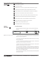
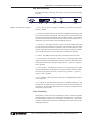
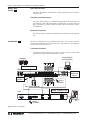
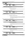
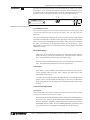
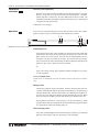
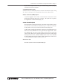
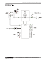
Audio PerfectTM 10
Installation and
Operations Manual
Copyright
Information
© Copyright 1997 Gentner Communications Corporation. All rights reserved. No part of this manual may be
reproduced in any form or by any means without written permission from Gentner Communications Corporation.
Printed in the United States of America. Original version, 12/97. Gentner Communications Corporation reserves
specification privileges. Information in this manual is subject to change without notice.
Audio PerfectTM 10 Installation and Operations Manual
Gentner Part No. 800-150-201 (Rev. 1.0)
March 1998
Manual Development: Bill Kilpack, Gerry Carpenter
Artwork and IIlustrations: Jim Wright, Bill Kilpack
The connection ports on the AP10 are to be used as follows:
Power
Connection to the power cord provided
G-Link
Interconnection of networked Audio Perfect™ products
Remote
Connection to an external controlling device
Receive
Connection to receive audio (output)
Transmit
Connection to transmit audio (input)
Telephone Line
Connection to telephone line
Telephone Set
Connection to telephone set
This equipment complies with the requirements of the EU guidelines:
89/336/EEC
“Electromagnetic Compatibility”
73/23/EEC
“Electrical operating material for use within specific
voltage limits”
Conformity of the equipment with the above guidelines is attested by the CE mark.
Gentner Communications Corporation is committed to protecting the environment
and preserving our natural resources.
This manual has been printed entirely on recycled paper.
Audio PerfectTM 10 Installation and Operations Manual
Contents
Introduction
Warranty Registration
1
1
Unpacking
1
Features and Benefits
2
Product Description
Front-Panel Controls
Rear-Panel Connectors
Touch-Tone Dialing
2
2
3
3
Before You Install
Power Requirements
Telephone Line Requirements
Equipment Placement
4
4
4
4
Installation
Completed Installation
Step 1 — Telephone Connections
Step 2 — Remote Connection
Step 3 — PhoenixTM Connector Wiring
Step 4 — G-Link Connections
Step 5 — Device ID (Dip Switches 9–12)
Step 6 — Power Connection
4
4
5
5
5
5
6
6
Operational Features
Dip Switch 1, Noise Burst/Auto-Adapt
Dip Switch 2, 6dB Receive Boose
Dip Switch 3, Receive Automatic Gain Control (AGC)
Dip Switch 4, Auto-Answer
Dip Switch 5, Auto-Disconnect
Dip Switch 6, Call Progression/Loop
Dip Switch 7, Receive Reduction
Dip Switch 8, Hook-Flash Duration
7
7
7
7
7
8
8
8
8
Calibration
Noise Burst Adapt
Auto-Adapt
Transmit Level Adjustment
Receive Level Adjustment
9
9
9
9
10
Operation
Answering a Call
Making a Call
Disconnecting a Call
Remote Connector (DB25) Option
Custom Controller Option
When Not in Use
10
10
10
10
11
11
11
Specifications
12
Warranty
13
FCC Part 15 Compliance
14
Technical or Setup Assistance
Telephone: 800.945.7730 (USA) or 801.975.7200 (worldwide) • http://www.gentner.com
Page iii
Page iv
Audio PerfectTM 10 Installation and Operations Manual
Contents continued
FCC Part 68 Compliance
14
IC Compliance
15
Safety Information
15
BABT Recording Requirements
16
Appendix A: Connector Pinouts
17
Appendix B: Serial Commands
18
Appendix C: AP10 Block Diagram
23
List of Figures
Figure 1.
Figure 2.
Figure 3.
Figure 4.
Figure 5.
Figure 6.
Figure 7.
Figure 8.
Figure 9.
Figure 10.
Figure 11.
Figure 12.
Figure 12a.
Equipment diagram
AP10 front-panel controls
AP10 back-panel connectors
System block diagram
AP10 back-panel connectors
RJ11C telephone-line connector
Remote DB25 connector
PhoenixTM three-terminal push-on connectors
G-Link connection diagram
AP10 power module
AP10 dip switches
AP10 front-panel controls
AP10 front-panel controls
1
2
3
4
4
5
5
5
5
6
7
9
10
List of Tables
Table 1. Device ID Dip Switch Settings
Table 2. Noise Burst/Auto-Adapt Dip Switch Settings
Table 3. 6dB Receive Boost Dip Switch Settings
Table 4. Receive AGC Dip Switch Settings
Table 5. Auto-Answer Dip Switch Settings
Table 6. Auto-Disconnect Dip Switch Settings
Table 7. Call Progression/Loop Dip Switch Settings
Table 8. Receive Reduction Dip Switch Settings
Table 9. Hook-Flash Duration Dip Switch Settings
Table 10. Remote Connector Pinout
Table 11. Line Connector Pinout
Table 12. Set Connector Pinout
Table 13. AP10 Serial Commands
6
7
7
7
8
8
8
8
8
17
17
17
18
Technical or Setup Assistance
Telephone: 800.945.7730 (USA) or 801.975.7200 (worldwide) • http://www.gentner.com
Audio PerfectTM 10 Installation and Operations Manual Page 1
Introduction
Congratulations on purchasing the Audio Perfect TM 10 (AP10) telephone interface.
The AP10 uses the latest digital technology to maintain the highest possible quality
audio. The AP10 is designed as an accessory to the Audio Perfect TM 800 (echo
cancelling, audio processing, microphone mixing matrix) to add telephone lines into
audioconferences.
The AP10 is a single-line digital hybrid which uses digital-signal processing (DSP)
to separate the transmit and receive audio, eliminating distortion, weak signals and
feedback. It continually filters low and high frequency noise to provide pure sound.
This manual explains how to install, set up and operate the AP10 in a step-by-step
format. It also supplies instructions on how to resolve technical problems, should
any arise.
If you need any additional information on how to install, set up or operate your system,
please contact us at Gentner Communications at the location noted below. We welcome
and encourage your comments so we can continue to improve our products and serve
your needs.
Gentner Communications Corporation
1825 Research Way
Salt Lake City, UT 84119
TEL: Worldwide 801.975.7200 In U.S.A. 800.945.7730
FAX: Worldwide 801.977.0087 In U.S.A. 800.933.5107
FAX-On-Demand 24-Hour Information Service 800.695.8110
FAX-On-Demand International Line 801.974.3661
Worldwide Web Page @ http://www.gentner.com
Warranty Registration
Please register your Audio PerfectTM product online by visiting Gentner Technical
Support at the World Wide Web address listed above. When your product is
properly registered, Gentner Communications will be able to serve you better
should you require technical assistance or desire to receive upgrades, new product
information, etc.
Unpacking
Ensure that the following items (See Figure 1, below) were received with your
shipment:
AP10 Installation
and Operations Manual
Phoenix Push-On
G-Link
Blocks (x2)
Terminator
AP10
AC
Power Cord
Figure 1. Equipment diagram
6-foot Telephone Cable
Audio Perfect 10
TM
18-inch G-Link
Jumper
SHIPPING NOTE:
Gentner Communications is not responsible for product damage incurred during
shipment. You must make claims directly with the carrier. Inspect your shipment
carefully for obvious signs of damage. If the shipment appears to be damaged,
retain the original boxes and packing material for inspection by the carrier. Contact
your carrier immediately.
Technical or Setup Assistance
Telephone: 800.945.7730 (USA) or 801.975.7200 (worldwide) • http://www.gentner.com
Page 2 Audio PerfectTM 10 Installation and Operations Manual
Features and
Benefits
Easy to install, easy to operate
DTMF dialing capability
Simultaneous two-wire/four-wire operation within an Audio Perfect™ system
G-Link network interconnection with up to eight AP800s and 16 AP10s.
9.6kHz sampling rate allows continual adaptation to telephone-line conditions
Full-time Telco echo cancellation with 26 millisecond tail time
Conference up to 16 callers (with 16 AP10s) within an Audio Perfect™ system
Digital anti-alias filter minimize hum and Central Office switching noise
Remote ON/OFF control via serial commands or rear-panel connection
Digital send filter/limiter for telephone line-noise reduction
Compatible with any analog telephone system
No outside RF interference will affect performance
Product
Description
Front-Panel Controls
The AP10 front-panel controls (See Figure 2, below) perform the following
functions:
1 2
Transmit
Receive
3 4
On
Off
5 6
Figure 2. AP10 front-panel controls
1. Transmit LED. This bicolor LED indicates the audio levels being transmitted
from the room to the telephone line.
2. Receive LED. This bicolor LED indicates the audio level the room is receiving
from the telephone line.
3. On LED. This bicolor LED indicates the hybrid’s ON state. The LED will
illuminate green when the hybrid is in the ON state.
4. Off LED. This bicolor LED indicates the hybrid’s OFF state. The LED will
illuminate red when the hybrid is in the OFF state.
5. On. The ON switch (momentary), connects the hybrid to the telephone line
(dependent upon dip switch settings), and automatically adapts the hybrid to the
line. Pressing and holding the ON button for more than a half-second while the
hybrid is active will readapt the hybrid.
6. Off. The OFF switch (momentary), disconnects the hybrid from the telephone
line and mutes all audio.
Technical or Setup Assistance
Telephone: 800.945.7730 (USA) or 801.975.7200 (worldwide) • http://www.gentner.com
Audio PerfectTM 10 Installation and Operations Manual Page 3
Rear-Panel Connectors
The AP10 back-panel connectors (See Figure 3, below) perform the following
functions:
VOLTAGE RANGE 100v-240V 2A
FREQUENCY 50Hz/60Hz
G-LINK
IN
1
Figure 3. AP10 back-panel connectors
REMOTE
TRANSMIT
INPUT
RECEIVE
OUTPUT
TELCO
LINE
SET
OUT
23
4
5
6
78
1. Power. The AC power cord input is a NEMA type connector allowing 100–
240Vac, 50/60Hz.
2. G-Link In. This RJ45 connector is part of the G-Link RS485 LAN that provides
serial control and status of the hybrid. The first Gentner unit in the local G-Link
network must terminate G-LINK IN with a G-Link terminator. Other Gentner
units in the local G-Link network must connect the previous Gentner unit’s GLINK OUT to the next Gentner unit’s G-LINK IN connector.
3. G-Link Out. This RJ45 connector is part of the G-Link RS485 LAN that
provides serial control and status of the hybrid. The last Gentner unit in the local
G-Link network must terminate G-Link OUT with a G-Link terminator. Other
Gentner units in the local G-Link network must connect the following Gentner
unit’s G-Link IN to the previous Gentner unit’s G-LINK OUT connector.
4. Remote. This DB25 connector provides control and status of the AP10.
5. Transmit Input. This PheonixTM connector is for connecting transmit audio
(input) with the three-terminal PhoenixTM push-on connector to the AP800. Note
that each position has three possible wiring positions: + (positive), - (negative)
and ò (ground).
6. Receive Output. This PheonixTM connector is for connecting receive audio
(output) with the three-terminal PhoenixTM push-on connector from the AP800.
Note that each position has three possible wiring positions: + (positive), (negative) and ò (ground).
7. Line. This RJ11 connector provides connection of a standard analog telephone
line to the hybrid.
8. Set. This RJ11 connector allows connection to a standard telephone set. Tip
and ring from the phone line are present at this connector when the hybrid is in
its OFF state. Tip and ring from the phone line are not present at this point when
the hybrid is in its ON state.
Touch-Tone Dialing
Through the G-Link (and serial commands), the AP10’s touch-tone (DTMF)
dialing capability can be accessed. This allows outbound calls to be initiated by
the AP10 without requiring an external dialer or telephone set. This feature
continues to function after connection, enabling the user to issue tones for voice
mail/pager interaction.
Technical or Setup Assistance
Telephone: 800.945.7730 (USA) or 801.975.7200 (worldwide) • http://www.gentner.com
Page 4 Audio PerfectTM 10 Installation and Operations Manual
Before You
Install
Power Requirements
The AP10 automatically accommodates voltage requirements of 100–240Vac,
50/60Hz, 30W.
Telephone Line Requirements
The AP10 model operates on a standard analog telephone line and connects to
the telephone system with a standard RJ11C modular jack. If you do not have an
RJ11C jack where you want to install your AP10, call your telephone company
for installation.
Equipment Placement
The AP10 models are designed for installation into a standard 19-inch equipment
rack.
Installation
The AP10 is designed for easy installation and setup. All necessary interface
connection are made through rear-panel connectors. This makes for easy installation,
removal and, if necessary, service.
Completed Installation
The following block diagram (See Figure 4, below) shows the AP10 when
installation is complete in an Audio PerfectTM system.
Control System
or PC (Optional)
Speakers
External Power Amp
AP800
Logic Out
Status and
Control
Video
CODEC
G-Link
Terminator
Tape Player (Optional)
Analog Telephone Line
AP10
VOLTAGE RANGE 100v-240V 2A
FREQUENCY 50Hz/60Hz
G-LINK
IN
REMOTE
TRANSMIT
INPUT
RECEIVE
OUTPUT
TELCO
LINE
SET
OUT
G-Link
Terminator
Telephone
Set
Figure 4. System block diagram
Technical or Setup Assistance
Telephone: 800.945.7730 (USA) or 801.975.7200 (worldwide) • http://www.gentner.com
Audio PerfectTM 10 Installation and Operations Manual Page 5
Refer to AP10 back-panel connections (See Figure 5, below) for a description
and placement of each of the connections you will be making. Each connector is
numbered for easy identification. To install your AP10, follow these step-bystep instructions:
VOLTAGE RANGE 100v-240V 2A
FREQUENCY 50Hz/60Hz
G-LINK
IN
2 3
1
Figure 5. AP10 back-panel connectors
TELCO
LINE
SET
RECEIVE
OUTPUT
TRANSMIT
INPUT
REMOTE
OUT
4
5
6
78
Step 1 — Telephone Connections
Line. Plug your telephone line from the source into the RJ11C LINE jack [7]
(Figure 6, left).
6
Set. Plug your telephone set into the RJ11C SET jack [8].
1
Figure 6 RJ11C telephone-line connector
Step 2 — Remote Connection
If using a remote control for parallel control and hybrid status, plug it into the
DB25 REMOTE connector [4] (Figure 7, left).
Step 3 — PhoenixTM Connector Wiring: Transmit/Receive
Figure 7. Remote DB25 connector
Wire the AP800 to the AP10 using the provided three-terminal PhoenixTM pushon connectors. These connectors are designed for easy wiring; simply insert the
desired wire into the appropriate connector opening (See Figure 8, left) and
tighten down the top screw.
Transmit Input
Audio connected to the TRANSMIT INPUT [5] will be sent down the telephone
line.
Figure 8. PhoenixTM three-terminal
push-on connectors
Receive Output
Audio from the RECEIVE OUTPUT [6] (telephone participant audio) is passed
to the AP800 for further routing and distribution (Figure 4, previous page).
CONNECTOR NOTE:
The three terminals in the PhoenixTM connector correspond with the back-panel audio
contacts (from left to right): + (positive), - (negative) and ò (ground).
Step 4 — G-Link Connections
Place the Gentner units in proper locations. The back-panel G-LINK IN [2] and
G-LINK OUT [3] connectors (See Figure 9, below) are designed for setting up
your G-Link network. G-Link connections between Gentner units are connected
in a daisy-chain fashion using category five twisted-pair cable.
G-Link
Terminator
First Gentner Unit (AP 800 )
Second Gentner Unit (AP 10 )
V OLTAGE RANGE 100v-240V 2A
FREQUENCY 50Hz/60Hz
G-LI NK
IN
OUT
RE MOTE
TRANS MI T
INP UT
RE CE I VE
OUTP UT
TE LCO
LI NE
S ET
G-Link
Audio: Transmit and Receive
V OLTAGE RANGE 100v-240V 2A
FREQUENCY 50Hz/60Hz
Last Gentner
Unit (AP 10 )
TRANS MI T
INP UT
RE MOTE
G-LI NK
IN
OUT
RE CE I VE
OUTP UT
TE LCO
LI NE
S ET
G-Link
G-Link
Terminator
Figure 9. G-Link connection block diagram
Technical or Setup Assistance
Telephone: 800.945.7730 (USA) or 801.975.7200 (worldwide) • http://www.gentner.com
Page 6 Audio PerfectTM 10 Installation and Operations Manual
Installation
Continued
G-LINK NETWORK NOTE:
If the Gentner units to be networked are stacked vertically, connect them using the
short RJ45 jumper (provided). If networking Gentner units (maximum distance 20
feet between units), Gentner Communications recommends that category five twistedpair (10BaseT LAN) cable be used.
The first Gentner unit in the chain must have the G-LINK IN connector [2]
terminated with a G-Link terminator (provided). The first Gentner unit’s GLINK OUT connector [3] is then attached to the G-LINK IN [2] connector on
the next unit in the chain. At the end of the network, the final unit must have the
G-LINK OUT connector [3] terminated with a G-Link terminator as well. A GLink network will allow interconnection of up to 16 AP10s and eight AP800s.
Step 5 — Device ID (Dip Switches 9–12)
Once your physical G-Link network is established, you need to set up unique GLink device ID numbers for each AP10 on the network. As shipped from the
factory, all AP10 units default as binary address 0. Set Device ID numbers for
each Gentner unit at your site by manipulating front-panel dip switches 9–12,
selecting/deselecting each switch to set up address 0–15 in binary code. Table 1
(below) illustrates how this is done.
Set the device ID for each AP product on the G-Link network.
DEVICE ID CONFLICT ERROR NOTE:
If more than one AP10 is assigned the same device ID number, the TRANSMIT and
RECEIVE LEDs will flash back and forth on the affected units until the error is
corrected.
Table 1. Device ID Dip
Switch Settings
Binary
Address
0
1
2
3
4
5
6
7
8
9
10 (A)
11 (B)
12 (C)
13 (D)
14 (E)
15 (F)
Dip Switch 9
Position
0 (DOWN)
0 (DOWN)
0 (DOWN)
0 (DOWN)
0 (DOWN)
0 (DOWN)
0 (DOWN)
0 (DOWN)
1 (UP)
1 (UP)
1 (UP)
1 (UP)
1 (UP)
1 (UP)
1 (UP)
1 (UP)
Dip Switch 10
Position
0 (DOWN)
0 (DOWN)
0 (DOWN)
0 (DOWN)
1 (UP)
1 (UP)
1 (UP)
1 (UP)
0 (DOWN)
0 (DOWN)
0 (DOWN)
0 (DOWN)
1 (UP)
1 (UP)
1 (UP)
1 (UP)
Dip Switch 11
Position
0 (DOWN)
0 (DOWN)
1 (UP)
1 (UP)
0 (DOWN)
0 (DOWN)
1 (UP)
1 (UP)
0 (DOWN)
0 (DOWN)
1 (UP)
1 (UP)
0 (DOWN)
0 (DOWN)
1 (UP)
1 (UP)
Dip Switch 12
Poisition
0 (DOWN)
1 (UP)
0 (DOWN)
1 (UP)
0 (DOWN)
1 (UP)
0 (DOWN)
1 (UP)
0 (DOWN)
1 (UP)
0 (DOWN)
1 (UP)
0 (DOWN)
1 (UP)
0 (DOWN)
1 (UP)
Step 6 — Power Connection
The power cord [1] (See Figure 10, left) will operate at any level between 100–
240Vac, 50–60Hz, 30W.
Hardware installation is now complete.
Figure 10. AP10 power module
Technical or Setup Assistance
Telephone: 800.945.7730 (USA) or 801.975.7200 (worldwide) • http://www.gentner.com
Audio PerfectTM 10 Installation and Operations Manual Page 7
Operational
Features
The AP10 has a variety of operational features selectable through dip-switch settings,
including noise burst/auto-adapt, receive AGC control, auto-answer, auto-disconnect,
call progression/loop, receive reduction and hook-flash duration. Default settings
(as shipped from the factory) are denoted by an asterisk “*”.
CALL PROGRESSION
AUTO DISCONNECT
AUTO ANSWER
RECEIVE AGC
RECEIVE BOOST
BURST ADAPT
RECEIVE REDUCTION
HOOK DURATION
DEVICE ID
DEVICE ID
DEVICE ID
DEVICE ID
Figure 11. AP10 dip switches
Dip Switch 1, Noise Burst/Auto-Adapt
In some applications, it may be desirable to adapt the hybrid with a white-noise
burst, rather than allowing the hybrid to adapt automatically to line conditions.
To enable this feature, dip switch 1 behind the digital hybrid’s front panel is used
to enable/disable the noise burst (Table 2, below).
Table 2. Noise Burst Auto-Adapt Dip Switch Settings
Dip Switch
1
1*
Position
ON (UP)
OFF (DOWN)
Description
Burst adapt
Auto-adapt
Dip Switch 2, 6dB Receive Boost
In some applications, it may be desirable to increase the receive audio by 6dB.
To enable this feature, dip switch 2 behind the digital hybrid’s front panel is used
to enable/disable the 6dB receive boost (Table 3, below).
Table 3. 6dB Receive Boost Dip Switch Settings
Dip Switch
2
2*
Position
ON (UP)
OFF (DOWN)
Description
6dB Receive Audio Boost Enabled
6dB Receive Audio Boost Disabled
Dip Switch 3, Receive Automatic Gain Control (AGC)
Dip switch 3 behind the digital hybrid’s front access panel enables/disables the
AGC function in the firmware (Table 4, below).
Table 4. Receive AGC Dip Switch Settings
Dip Switch
3*
3
Position
ON (UP)
OFF (DOWN)
Description
Receive AGC Enabled
Receive AGC Disabled
Dip Switch 4, Auto-Answer
Dip switches 4 behind the AP10’s front access panel enables/disables auto-answer
(Table 5, next page).
Technical or Setup Assistance
Telephone: 800.945.7730 (USA) or 801.975.7200 (worldwide) • http://www.gentner.com
Page 8 Audio PerfectTM 10 Installation and Operations Manual
Operational Features
Continued
Table 5. Auto-Answer Dip Switch Settings
Dip Switch
4
4*
Position
ON (UP)
OFF (DOWN)
Description
Auto-answer enabled
Auto-answer disabled (follows the serial command)
AUTO-ANSWER SERIAL COMMAND NOTE:
To issue the AA (auto-answer) serial command to toggle auto-answer, the dip switch 4 must be OFF (DOWN).
Dip Switch 5, Auto-Disconnect
Dip switch 5 behind the AP10’s front access panel enables/disables autodisconnect (Table 6, below).
Table 6. Auto-Disconnect Dip Switch Settings
Dip Switch
5*
5
Position
ON (UP)
OFF (DOWN)
Description
Auto-disconnect enabled
Auto-disconnect disabled
AUTO-DISCONNECT NOTE:
In order for the settings on Dip Switch 6 (below) to function, Dip Switch 5 (above) must be ON (UP). Auto-disconnect must
be enabled before either Call Progression or Loop Drop are applicable.
Dip Switch 6, Call Progression/Loop
Dip switch 6 selects either loop drop or call-progress mode. Call-progress mode
will disconnect the line upon detection of a valid call-progress signal (Table 7,
below). Call progress will detect reorder tone and busy for the U.S., Canada,
United Kingdom, France and Germany.
Table 7. Call Progression/Loop Dip Switch Settings
Dip Switch
6
6*
Position
ON (UP)
OFF (DOWN)
Description
Call progression enabled
Loop drop enabled
Dip Switch 7, Receive Reduction
In some applications, it may be necessary to duck the receive audio coming in
through the telephone line when transmit audio is present. To serve this purpose,
dip switch 7 is designated to duck the receive audio by -6dB, if active (Table 8,
below).
Table 8. Receive Reduction Dip Switch Settings
Dip Switch
7
7*
Position
ON (UP)
OFF (DOWN)
Description
Receive reduction enabled
Receive reduction disabled
Dip Switch 8, Hook-Flash Duration
Dip switch 8 selects either a 50 millisecond or 500 millisecond hook-flash duration
(Table 9, below).
Table 9. Hook-Flash Duration Dip Switch Settings
Dip Switch
8
8*
Position
ON (UP)
OFF (DOWN)
Description
50 milliseconds
500 milliseconds
Technical or Setup Assistance
Telephone: 800.945.7730 (USA) or 801.975.7200 (worldwide) • http://www.gentner.com
Audio PerfectTM 10 Installation and Operations Manual Page 9
Calibration
The following information will help you make adjustments to optimize your system
performance. Verify all components and all connections. Ensure that proper power
is supplied to the AP10 and that the unit is OFF (the red OFF LED [4] will be lit;
Figure 12, below). If the green ON LED [3] is lit, press the OFF button [6].
1 2
Transmit
Receive
3 4
On
Off
5 6
Figure 12. AP10 front-panel controls
CALIBRATION NOTE:
Some echo and ringing may be heard while calibrating the AP10. Disregard it and
continue with calibration until the end of the procedure. The echo and ringing will
disappear.
There are two calibration methods for the AP10: noise burst and auto-adapt. Which
procedure is used depends on whether you have dip switch 1 ON (UP) for noise-burst
adapt, or dip switch 1 OFF (DOWN) for auto-adapt. Either will suffice to calibrate
the AP10. The difference is the application and/or personal preference. Some
applications are not suited for a .75-second noise burst, and may require the gradual
adaptation over time.
Noise-Burst Adapt
If dip switch 1 is ON (UP), have someone call the AP10 from another location.
Answer the line by pressing the ON button [5]. (If the auto-answer feature is
active, the unit will answer the call after one complete ring.)
The caller will hear a short white noise burst (it will sound like static) and a short
beep. This automatically adapts the AP10 to the telephone line.
Auto-Adapt
If dip switch 1 is OFF (DOWN), call someone and continue to talk while the
system gradually adapts over time. Once complete, the AP10 will be fully
calibrated and ready for use.
Conclude your conversation and press the OFF button [6]. (If the auto-disconnect
feature is active, and the distant location hangs up, the AP10 will disconnect
upon sensing loop drop or call-progress tones, depending on the position of dip
switch 6.)
Transmit Level Adjustment
AP10 NOTE:
AP10 transmit and receive audio level adjustments are made via the AP800. Nominal
transmit and receive level for the AP10 is 0dB.
Someone in the local room should speak into the microphone at a normal distance,
in a normal voice. The party at the distant location should not speak during the
transmit adjustment. Adjust the AP800 output that is connected to the AP10
TRANSMIT INPUT to 0dB. The AP10 TRANSMIT LED [1] should be solid
green while the person is speaking and extinguish when the person stops.
Technical or Setup Assistance
Telephone: 800.945.7730 (USA) or 801.975.7200 (worldwide) • http://www.gentner.com
Page 10 Audio PerfectTM 10 Installation and Operations Manual
Calibration
Continued
Receive Level Adjustment
Someone in the distant location should speak into the microphone at a normal
distance, in a normal voice; the local room should maintain silence. Adjust the
AP800 input that is connected to the AP10 RECEIVE OUTPUT to 0dB. The
AP10 RECEIVE LED [2] should be solid green while the person is speaking and
extinguish when the person stops.
Calibration is now complete.
Operation
Easy-to-access and read front-panel controls make operation of the AP10 simple.
Figure 12a (below) shows each front panel LED and button by number.
1 2
Transmit
Receive
3 4
On
Off
5 6
Figure 12a. AP10 front-panel controls
Answering a Call
An incoming call will ring on the telephone set connected to the AP10 and flash
the ON LED. Answer the call by pressing the ON button [5] on either the front
panel or from your remote control. This will route the call through the AP10 to
the AP800. The green ON LED [3] will light. The red OFF LED [4] will dim.
Upon connection, the AP10 automatically (method of adaptation depends on the
position of dip switch 1) adjusts to the line conditions.
Or
Answer the call by picking up the telephone handset and talking to your party
over the telephone.
AUTO-ANSWER NOTE:
If auto-answer is enabled (dip switch 4), the AP10 will answer after the first complete
ring.
Making a Call
Call the party normally, using your handset. After the other party has answered,
route the call through the AP10 by pressing the ON button [5]. The ON LED [3]
will light and the AP10 will take control of the call, disabling the telephone set.
You may now safely hang up the handset without disconnecting your call. When
the conversation is complete, press the OFF button [6] to disconnect the call.
If using RS232 touch tone, it is not necessary to hit the ON button [5]. When
using the DIAL serial port command, the AP10 automatically engages the hybrid.
See Appendix B: Touch-Tone Dialing (Page 19).
Disconnecting a Call
If the call is routed through the AP10 (the ON LED [3] will glow), press the OFF
button [6] (OFF LED [4] will glow, ON LED [3] will extinguish).
Technical or Setup Assistance
Telephone: 800.945.7730 (USA) or 801.975.7200 (worldwide) • http://www.gentner.com
Audio PerfectTM 10 Installation and Operations Manual Page 11
If your call is through the handset only (the red OFF LED [4] will be lit), hang up
when the conversation is complete.
AUTO-DISCONNECT NOTE:
If auto-disconnect is enabled (dip switch 5), the AP10 will disconnect upon sensing
loop drop or call-progress tones (depending on the position of dip switch 6).
Remote Connector (DB25) Option
A customer-supplied remote control or contact-closure switch can be used to
perform three functions: mute on/off, system on, and system off. For pinouts,
see Appendix A: Connector Pinouts (Page 17).
Custom Controller Option
The AP products are designed to function with serial custom control systems.
The controller is connected to the AP800 RS232 port. Via the G-Link network,
all AP products can be accessed and controlled from that single point.
Via the custom controller, the AP10 can be turned on or off; transmit and receive
audio can be muted; DTMF tones can be generated (See Appendix B: TouchTone Dialing, Page 19); receive audio volume can be raised or lowered; the
AP10’s binary address can be queried; telephone hybrid can be renulled; input
and output can be metered; and ERL and ERLE can be read. These commands
are also available in the AP Tools software which communictates with the AP10
via an AP800 RS232 serial port and the G-Link LAN.
When Not in Use
The AP10 is inactive when the red OFF LED [4] lit.
Technical or Setup Assistance
Telephone: 800.945.7730 (USA) or 801.975.7200 (worldwide) • http://www.gentner.com
Page 12 Audio PerfectTM 10 Installation and Operations Manual
Specifications
AP10
Dimensions
17"/43.2cmW x 1.75"/4.5cmH x 8"/25.4cmD
Weight
7 lbs/3.18 kg (dry)
12 lbs./5.4 kg (shipping)
Connectors
POWER:
Auto-adjusting power module from 100–240Vac, 50/60Hz
REMOTE:
DB25 female connector.
G-LINK IN:
RS485; 38.4kbps; 110kOhm impedance, category-five twistedpair cable; 20-foot limit between networked units
G-LINK OUT: RS485; 38.4kbps; 110kOhm impedance, category-five twistedpair cable; 20-foot limit between networked units
TRANSMIT
INPUT:
Push-on terminal block with slotted set-screw connectors; +, -, ò
contacts provided at terminal block at +20dBm maximum input,
0dBu nominal level, >20kOhm impedance
RECEIVE
OUTPUT:
Push-on terminal block with slotted set-screw connectors; +, -, ò
contacts provided at terminal block at +20dBm maximum input,
0dBu nominal level, <50 Ohm impedance
LINE:
RJ11 connector
SET:
RJ11 connector
Power Requirements
100–240Vac, 50/60Hz, 30W
Audio Performance
Frequency Response
1dB from 250Hz to 3.5kHz (with AGC disabled)
Signal-to-Noise Ratio
>56dB reference to 0dBu at -15dBm on the telephone line
Receive Audio: Distortion
<.3% THD, 250Hz to 3.5kHz (AGC disabled)
Audio Interface
Unbalanced Transmit Audio
DB25; 0dB level input with a >10kOhm impedance
Unbalanced Receive Audio
DB25; 0dB level output with a <50Ohm impedance
Remote Control
Momentary closures to the switch common.
Technical or Setup Assistance
Telephone: 800.945.7730 (USA) or 801.975.7200 (worldwide) • http://www.gentner.com
Audio PerfectTM 10 Installation and Operations Manual Page 13
Transmit and Receive Presence Indication
Open collector outputs go low when transmit and/or receive levels are present
Operating Temperature
32–100° F / 0–38° C
Humidity
0–80 percent
All specifications are subject to change without notice.
Warranty
Gentner Communications Corporation (Manufacturer) warrants that this product is free of defects in both materials and
workmanship. Should any part of this equipment be defective, the Manufacturer agrees, at its option, to:
A. Repair or replace any defective part free of charge (except transportation charges) for a period of one year from the date
of the original purchase, provided the owner returns the equipment to the Manufacturer at the address set forth below. No
charge will be made for parts or labor during this period;
B. Furnish replacement for any defective parts in the equipment for a period of one year from the date of original purchase.
Replacement parts shall be furnished without charge, except labor and transportation.
This Warranty excludes assembled products not manufactured by the Manufacturer whether or not they are incorporated in
a Manufacturer product or sold under a Manufacturer part or model number.
THIS WARRANTY IS VOID IF:
A. The equipment has been damaged by negligence, accident, act of God, or mishandling, or has not been operated in
accordance with the procedures described in the operating and technical instructions; or,
B. The equipment has been altered or repaired by other than the Manufacturer or an authorized service representative of the
Manufacturer; or,
C. Adaptations or accessories other than those manufactured or provided by the Manufacturer have been made or attached
to the equipment which, in the determination of the Manufacturer, shall have affected the performance, safety or reliability
of the equipment; or,
D. The equipment’s original serial number has been modified or removed.
NO OTHER WARRANTY, EXPRESS OR IMPLIED, INCLUDING WARRANTY OF MERCHANTABILITY OR
FITNESS FOR ANY PARTICULAR USE, APPLIES TO THE EQUIPMENT, nor is any person or company authorized to
assume any warranty for the Manufacturer or any other liability in connection with the sale of the Manufacturer's products.
Manufacturer does not assume any responsibility for consequential damages, expenses, or loss of revenue or property,
inconvenience, or interruption in operation experienced by the customer due to a malfunction in the purchased equipment.
No warranty service performed on any product shall extend the applicable warranty period.
In case of unsatisfactory operation, the purchaser shall promptly notify the Manufacturer at the address set forth below in
writing, giving full particulars as to the defects or unsatisfactory operation. Upon receipt of such notice, the Manufacturer
will give instructions respecting the shipment of the equipment, or such other matters as it elects to honor this warranty as
above provided. This warranty does not cover damage to the equipment during shipping and the Manufacturer assumes no
responsibility for such damage. All shipping costs shall be paid by the customer.
This warranty extends only to the original purchaser and is not assignable or transferable.
Gentner Communications Corporation, 1825 Research Way, Salt Lake City, Utah 84119
Technical or Setup Assistance
Telephone: 800.945.7730 (USA) or 801.975.7200 (worldwide) • http://www.gentner.com
Page 14 Audio PerfectTM 10 Installation and Operations Manual
FCC Part 15
Compliance
This equipment has been tested and found to comply with the limits for a Class A digital device, pursuant to Part 15 of the
FCC rules. These limits are designed to provide reasonable protection against harmful interference when the equipment is
operated in a commercial environment. This equipment generates, uses, and can radiate radio frequency energy and, if not
installed and used in accordance with the instruction manual, may cause harmful interference to radio communications.
Operation of this equipment in a residential area is likely to cause harmful interference, in which case the user will be
required to correct the interference at his/her own expense.
Changes or modifications not expressly approved by Gentner Communications Corporation could void the user’s authority
to operate the equipment.
FCC Part 68
Compliance
FCC Registration Number: FBIUSA-31573-BR-N
Ringer Equivalence Number (REN): 1.1B
A label containing, among other information, the FCC registration number and Ringer Equivalence Number (REN) for this
equipment is prominently posted on the top plate, near the rear of the equipment. If requested, this information must be
provided to your telephone company.
USOC Jacks: This device uses RJ11C and RJ21X terminal jacks.
The REN is used to determine the quantity of devices which may be connected to the telephone line. Excessive RENs on the
telephone line may result in the devices not ringing in response to an incoming call. In most, but not all areas, the sum of the
RENs should not exceed five (5). To be certain of the number of devices that may be connected to the line, as determined by
the total RENs, contact the telephone company to obtain the maximum RENs for the calling area.
If this equipment causes harm to the telephone network, the telephone company will notify you in advance that temporary
discontinuance of service may be required. If advance notice is not practical, the telephone company will notify the customer
as soon as possible. Also, you will be advised of your right to file a complaint with the FCC if you believe it is necessary.
The telephone company may make changes in its facilities, equipment, operations, or procedures that could affect the
operation of the equipment. If this happens, the telephone company will provide advance notice for you to make the necessary
modifications in order to maintain uninterrupted service.
If you experience problems with this equipment, contact Gentner Communications Corporation, 1825 Research Way, Salt
Lake City, Utah 84119, or by phone at (801) 975-7200 for repair and warranty information. If the trouble is causing harm to
the telephone network, the telephone company may request you remove the equipment from the network until the problem
is resolved.
No user serviceable parts are contained in this product. If damage or malfunction occurs, contact Gentner Communications
for instructions on its repair or return.
This equipment cannot be used on telephone company provided coin service. Connection to Party Line Service is subject to
state tariffs.
Technical or Setup Assistance
Telephone: 800.945.7730 (USA) or 801.975.7200 (worldwide) • http://www.gentner.com
Audio PerfectTM 10 Installation and Operations Manual Page 15
IC Compliance
NOTICE: The Industry of Canada label identifies certified equipment. This certification means that the equipment meets
certain telecommunications network protective operational and safety requirements. The Department does not guarantee the
equipment will operate to the user's satisfaction.
Before installing this equipment, users should ensure that it is permissible to be connected to the facilities of the local
telecommunications company. The equipment must also be installed using an acceptable method of connection. In some
cases, the company's inside wiring associated with a single line individual service may be extended by means of a certified
connector assembly (telephone extension cord). The customer should be aware that compliance with the above conditions
may not prevent degradation of service in some situations.
Repairs to certified equipment should be made by an authorized Canadian maintenance facility designated by Gentner
Communications. Any repairs or alterations made by the user to this equipment, or equipment malfunctions, may give the
telecommunications company cause to request the user to disconnect the equipment.
Users should ensure for their own protection that the electrical ground connections of the power utility, telephone lines and
internal metallic water pipe system, if present, are connected together. This precaution may be particularly important in rural
areas.
Ringer Equivalence Number (REN): 1.1
IC Certification Number: 1970 8175 A
Safety
Information
CAUTION: Users should not attempt to make such connections themselves, but should contact the appropriate electrical
inspection authority, or electrician, as appropriate.
Technical or Setup Assistance
Telephone: 800.945.7730 (USA) or 801.975.7200 (worldwide) • http://www.gentner.com
Page 16 Audio PerfectTM 10 Installation and Operations Manual
BABT Recording
Requirements
This condition applies in circumstances where you wish to use telecommunications apparatus comprised in or connected to
your system to record, silently monitor or intrude into live-speech telephone calls. (It does not apply where the apparatus in
question is not telecommunications apparatus; i.e. is not apparatus that had been constructed or adapted for use in transmitting
or receiving telecommunications messages.) Silent monitoring is the establishment of a receive-only transmission path to a
third terminal, enabling a third party to hear the call. Intrusion is the establishment of a bothway speech transmission to
another terminal enabling a third party to hear and be heard by at least one of the other parties to the call. The condition does
not apply to the monitoring of telephone calls for a systems control or diagnostic purposes where the meaningful content of
the call itself is monitored.
This condition provides that you should make every reasonable effort to inform all parties to a call that it may or will be
recorded, silently monitored or intruded into. The particular means by which you choose to do this are not specified in the
condition. Acceptable options, depending on circumstances, might include warning tones, prerecorded messages, spoken
warnings by the operator or written warnings included in publicity material, telephone directories, contracts, terms of business,
staff notices, etc. It may not always be possible to warn first-time callers with whom you have had no previous contact but
what is important is that you have a systemic procedure in place which provides the necessary information wherever this is
a realistic possibility.
For recording and silent monitoring, this condition recognises two forms of warning: a written notice before the call or a
warning during the call itself. Both warnings should also inform all parties to a call why it is being recorded or silently
monitored. In the case of intrusion, a warning before the intrusion takes place is sufficient as both parties will become aware
that a third party has joined their conversation.
This condition does not specify the detail of how these forms of warning should be given. A written statement included in
any of the following — contractural terms, conditions of employment, publicity material, staff notices, telephone directory
entries — would be a possible method.
The essential point is that the equipment user must be able to demonstrate that a determined attempt has been made to reach
prospective callers; as an illustration, we would expect any warning included in a company’s publicity material to be presented
in such a way that it would not be missed by anyone looking for that company’s telephone number(s). A warning which is
not clearly visibly would fail to meet this requirement.
Where the warning is to be given during the call itself, the possibilities include a recorded message at the beginning of the
call or a spoken message at any time during the conversation.
You should also maintain a record of the means by which callers have been warned which the Director may request sight of.
This does not mean that you have to log each phone call; rather, that should a dispute arise, it will be possible for you to show
from records how callers were being made aware at the time.
This condition does not apply where apparatus is being used for the purpose of law enforcement or in the interests of national
security or to calls involved the national Emergency Organizations. It also provides that other licensees may be excluded, by
means of a Director’s consent, where there are compelling factors that outweigh the normal expectation of privacy. Such
factors might apply where security is a consideration or in the case of specialized users such as helplines. In accordance with
Section 19 of the Telecommunications Act of 1984, these consents will be entered on a register open to public inspection.
This condition attempts to secure objectives similar to those which were previously achieved through an approval requirement
that equipment capable of recording, silently monitoring or intruding into telephone conversations should emit warning
tones as these operations take place. The removal of warning tones was permitted by an OFTEL General Variation provided
that an alternative form of warning was given. The expectation is that procedures complying with the General Variation
should, generally, also meet the requirements of this condition.
Technical or Setup Assistance
Telephone: 800.945.7730 (USA) or 801.975.7200 (worldwide) • http://www.gentner.com
Audio PerfectTM 10 Installation and Operations Manual Page 17
Appendix A:
Connector Pinouts
Table 10. Remote Connector Pinout
Pin
1
2
3
4
5
6
7
8
9
10
11
12
13
Description
Remote ON *
Remote OFF *
N/C
N/C
Switch/Indicator Common
N/C
N/C
N/C
Unbalanced Transmit Audio Input (0dBu nominal)
Unbalanced Receive Audio Output (0dBu nominal)
N/C
N/C
Audio Common
Pin
14
15
16
17
18
19
20
21
22
23
24
25
Description
ON indication **
OFF indication **
N/C
N/C
Switch/Indicator Common
Transmit Presence Indicator **
Receive Presence Indicator **
Switch/Indicator Common
Audio Common
Audio Common
Audio Common
Switch/Indicator Common
* Remote control provided via contact closure to Switch/Indicator Common
** Remote indicators provided via open collector outputs to Indicator Common (<15V, <39mA)
Table 11. Line Connector Pinout
Pin
1
2
3
Description
To pin 6 of LINE RJ11C
To pin 5 of LINE
Tip
Pin
4
5
6
Description
Ring
To pin 2 of SET
To pin 1 of SET RJ11C
Pin
4
5
6
Description
Tip
To pin 2 of LINE
To pin 1 of LINE RJ11C
Table 12. Set Connector Pinout
Pin
1
2
3
Description
To pin 6 of SET RJ11C
To pin 5 of SET
Ring
Technical or Setup Assistance
Telephone: 800.945.7730 (USA) or 801.975.7200 (worldwide) • http://www.gentner.com
Page 18 Audio PerfectTM 10 Installation and Operations Manual
Appendix B: Serial
Commands
The AP products accept serial commands via the AP800’s serial port; the commands
are then channeled along the G-Link network to all interconnected AP products. In
the case of the AP10, the commands provide the same control as the front-panel
controls, plus several others. The following commands pertain only to the AP10.
AP800 RS232 Serial Port Default Protocol (9,600 (default), 19,200 or 38,400 baud, 8 bits, 1 stop bit, no parity)
The AP10, via custom controller, will issue DTMF tones in the form of telephone-keypad digits (0–9), the * and # keys
(for dialing and accessing voice-mail/pager). Also via custom controller, the AP10 will accept serial commands outlined
in Table 13 (below).
The structure of serial commands is as follows: “#” (which signifies the start of a command line), device ID, command,
then any additional options in the order that they appear in the command descriptions on the following pages. For
example, a command to enable auto-answer on AP10 device “0” would have the command line: #20 AA 1. In this
command line, 2=AP10, 0=unit 0, AA=command, 1=on state). If a command calls for a “null” value, leave a blank in
the command line (i.e. “#20 AA” would return the current state of auto-answer on device 20). Commands can be either
UPPER CASE or lower case. Return values are always in upper case. In order for a command to be recognized by the
serial port, the command must be terminated by a carriage return.
Command Syntax
All command lines will be set off by the flag symbol “O”. The serial command line that follows the “O” uses the
following typographic conventions:
<X>
[X]
1-8
4,7,9
AA
<DEVICE>
Parameters enclosed in “< >” indicate a mandatory parameter
Parameters enclosed in “[ ]” indicate an optional parameter
Parameters separated by a “-” indicate a range between the values
Parameters separated by a “,” indicate a list of available values
Words in ALL CAPS bold indicate command text
Device type/number on G-Link network (valid combinations depend on connected devices:
for an AP10, device type is 2, device number will always be 0–9, A–F, where A=10 and
F=15). See Table 1, Device ID Dip Switch Settings (Page 6).
The command string will then be explained (where necessary), followed by the returned values and (where necessary)
an example.
Table 13. AP10 Serial Commands
Command
AA
DIAL
HOOK
LVL
MUTE
NULL
Function
Auto-answer
Dial touch-tones
Send hook-flash to the line
Return transmit/receive level
Control/report mute status*
Renulls AP10 to telephone line
Command
RING
TE
TERL
TERLE
UID
VER
Function
Ring acknowledgement
Control/report the connect state of the unit
Return telephone ERL
Return telephone ERLE
Return unit identification number
Return current version of software
* Applied to a specific channel
Technical or Setup Assistance
Telephone: 800.945.7730 (USA) or 801.975.7200 (worldwide) • http://www.gentner.com
Audio PerfectTM 10 Installation and Operations Manual Page 19
AA
This command activates and deactivates the auto-answer feature.
O
<DEVICE> AA <X>
Explanation
<X> is the action (i.e. auto-answer enable, auto-answer diasable, current state)
X=0
Parameter disables auto-answer
X=1
Parameter enables auto-answer
X=2
Parameter to toggle the state from one state to the other (regardless of current state)
X= Null
Parameter to report back the current state.
DIP SWITCH 4 NOTE:
This serial command only functions if dip switch 4 is OFF (DOWN).
DIAL
DTMF tones can be generated through the AP10. This capability remains active after a call is placed, so tones can be
issued for use with voice mail and pagers.
CONNECTION NOTE:
If the AP10 is not connected when this command is issued, the unit will connect to the line first, then dial the tone(s).
O <DEVICE> DIAL <STRING>
Explanation
<STRING> is any valid combination of touch tone characters. A comma indicates a two-second pause. STRING has a
maximum length of XX characters. Valid characters are: 0 through 9, A,B,C,D, #, * and ,
Return Values
DIAL returns the dialed string of numbers. The string is returned after the command has been completed (i.e. dialed all
the touch tones).
Example
The following command dials the number (801) 975-7200.
A 9 and a pause is generated to get an outside line on a PBX.
The number is to be dialed on device #20.
#20 DIAL 9,8019757200
The following is returned out the serial port:
#20 DIAL 9,8019757200
HOOK
This command sends a momentary interruption in line seizure (hook flash) to the telephone line. This command is write
only.
O <DEVICE> HOOK
Return Values
If hook flash succeeded, the following is returned out the serial port:
<DEVICE> HOOK
Example
The following command request hook flash from device 20:
#20 hook
The following is returned out the serial port:
#20 hook
Technical or Setup Assistance
Telephone: 800.945.7730 (USA) or 801.975.7200 (worldwide) • http://www.gentner.com
Page 20 Audio PerfectTM 10 Installation and Operations Manual
Appendix B:
Continued
The flag symbol “O” signals the start of a command line. For serial port command
protocol and syntax, see page 18.
LVL
This command reports back the transmit or receive level for a unit.
O <DEVICE> LVL <CH>
Explanation
<CH> is which parameter to be measured.
CH= RXIN
Parameter for level from the telephone line
CH=RXOUT
Parameter for level from the AP10
CH=TXIN
Parameter for level into the AP10
CH=TXOUT
Parameter for level to the telephone line
Return Values
LVL will return the output level of the line channel in the same format as the command.
Example
If is current level for RXIN channel is -20dBu, the following is returned out the serial port:
<DEVICE> LVL RXIN -20
MUTE
This command controls or reports the mute status of a channel .
O
<DEVICE> MUTE <CH> <X>
Explanation
<CH> is the channel(s) to be muted/unmuted.
CH=T
Parameter to apply to the transmit channel
CH=R
Parameter to apply to the receive channel
CH=*
Parameter to apply to both channels
<X> is the action (i.e. mute, unmute, report the mute state).
X=0
Set mute to off
X=1
Set mute to on (mute the selected channel)
X=2
Parameter to toggle the state from one state to the other (regardless of current state)
X=NULL
Report the current state of mute for the selected channel
Return Values
MUTE returns the mute status in the same format as the command.
Example
If current state of mute for channel T is muted,
the following is returned out the serial port:
<DEVICE> MUTE T 1
If current state of mute for channel T is unmuted,
the following is returned out the serial port:
<DEVICE> MUTE T 0
Technical or Setup Assistance
Telephone: 800.945.7730 (USA) or 801.975.7200 (worldwide) • http://www.gentner.com
Audio PerfectTM 10 Installation and Operations Manual Page 21
NULL
This command sends a short noise burst down the telephone line and forces the AP10 to adapt to the telephone line.
This command is write only.
O <DEVICE> NULL
Return Values
If the renull succeeded, the following is returned out the serial port:
<DEVICE> NULL
RING
When the AP10 receives a ring at the dialed-up location, the AP10 will respond
O RING
TE
Controls and reports the connection status of the unit.
O <DEVICE> TE <X>
Explanation
<X> is the action (i.e. connect, disconnect, current state)
X=0
Parameter to set the unit to disconnect from the line
X=1
Parameter to set the unit to connect to the line
X=2
Parameter to toggle the state from one state to the other (regardless of current state)
X= Null
Parameter to report back the current state.
Return Values
If the current connect state is ON, the following
is returned out the serial port:
<DEVICE> TE 1
<DEVICE> TE 0
Examples
The following connects the unit to the telephone line.
#20 TE 1
The following is returned out the serial port:
#20 TE 1
The following reports the connection state of the unit:
#20 TE
If the current connect state is OFF, the following
is returned out the serial port:
The following is returned out the serial port:
#20 TE 1
TERL
This command reports back the telephone echo return loss (ERL) for the AP10 in dB. This is a read-only
parameter.
O <DEVICE> TERL
Return Values
If the current TERL level is 10 dB, the following is returned out the serial port:
<DEVICE> TERL 10
Technical or Setup Assistance
Telephone: 800.945.7730 (USA) or 801.975.7200 (worldwide) • http://www.gentner.com
Page 22 Audio PerfectTM 10 Installation and Operations Manual
Appendix B:
Continued
The flag symbol “O” signals the start of a command line. For serial port command
protocol and syntax, see page 18.
TERLE
This command reports back the telephone echo return loss enhancement (ERLE) for the AP10 in dB. This is a readonly parameter.
O <DEVICE> TERLE
Return Values
If the current TERLE level for the telephone canceller is 20dB, the following is returned out the serial port:
<DEVICE> TERLE 20
UID
This command returns the unique ID number of the unit. This command is read only.
O <DEVICE> UID
Return Values
UID returns the unit ID code. The Unit ID is composed of an eight-digit hex number (assigned at the factory) to
uniquely identify the unit.
Example
This command requests the unit ID:
#20 UID
The following is returned out the serial port:
#20 UID A4EF906C
VER
This command returns current version of software. This version is unique to a released version of software. This
command is read only.
O <DEVICE> VER
Return Values
VER returns the version of software (a major version number followed by a period and a minor version number).
Example
The following command request the unit ID from device 21
#20 VER
The following is returned out the serial port:
#20 VER 1.0
Technical or Setup Assistance
Telephone: 800.945.7730 (USA) or 801.975.7200 (worldwide) • http://www.gentner.com
Audio PerfectTM 10 Installation and Operations Manual Page 23
Appendix C: AP10
Block Diagram
Technical or Setup Assistance
Telephone: 800.945.7730 (USA) or 801.975.7200 (worldwide) • http://www.gentner.com
Page 24 Audio PerfectTM 10 Installation and Operations Manual
Notes:
Technical or Setup Assistance
Telephone: 800.945.7730 (USA) or 801.975.7200 (worldwide) • http://www.gentner.com
WE PUT THE WORLD ON SPEAKING TERMSTM
GENTNER COMMUNICATIONS CORPORATION
Sales and Technical Assistance
1825 Research Way
Salt Lake City, Utah 84119
Toll Free 800.945.7730
Telephone 801.975.7200
FAX 801.977.0087
FAX-On-Demand 800.695.8110
FAX-On-Demand International Line 801.974.3661
Worldwide Web Page @ http://www.gentner.com
Gentner Part No. 800-150-201 (Rev. 1.0)