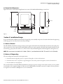
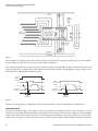
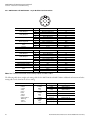
1
Pressure Sensitive Safety Mat System MatGuard™ Mat Manager Cat. No.: 440F-C28011, 440F-C28012, 440F-C28013, 440F-C28021, 440F-C28023, 440F-C28024, 440F-C28025, 440F-C28026 User Manual 440F MatGuard™ Mat Manager User Manual Important User Information In no event will Rockwell Automation, Inc. be responsible or liable for indirect or consequential damages resulting from the use or application of this equipment. The examples and diagrams in this manual are included solely for illustrative purposes. Because of the many variables and requirements associated with any particular installation, Rockwell Automation, Inc. cannot assume responsibility or liability for actual use based on the examples and diagrams. No patent liability is assumed by Rockwell Automation, Inc. with respect to use of information, circuits, equipment, or software described in this manual. Reproduction of the contents of this manual, in whole or in part, without written permission of Rockwell Automation, Inc., is prohibited. Throughout this manual, when necessary, we use notes to make you aware of safety considerations. WARNING IMPORTANT ATTENTION Identifies information about practices or circumstances that can cause an explosion in a hazardous environment, which may lead to personal injury or death, property damage, or economic loss. Identifies information that is critical for successful application and understanding of the product. Identifies information about practices or circumstances that can lead to personal injury or death, property damage, or economic loss. Attentions help you identify a hazard, avoid a hazard, and recognize the consequences. SHOCK HAZARD Labels may be on or inside the equipment (for example, drive or motor) to alert people that dangerous voltage may be present. BURN HAZARD Labels may be on or inside the equipment (for example, drive or motor) to alert people that surfaces may reach dangerous temperatures. We recommend that you save this user manual for future use. The following symbols are used in this manual for clarification. 2 Rockwell Automation Publication 95302194/EO:0240 Issue No: 8) 440F MatGuard™ Mat Manager User Manual Table of Contents Introduction . . . . . . . . . . . . . . . . . . . . . . . . . . . . . . . . . . . . . . . . . . . . . . . . . . . . . . . . . . . . . . . . . . . . . . . . . . . . . . . . . . . . . . . . . . . . . . . . . . . . . . . . . . . . . . . . . . . . . . . . . . . . . . . . .5 Section 1 - Storage and Handling . . . . . . . . . . . . . . . . . . . . . . . . . . . . . . . . . . . . . . . . . . . . . . . . . . . . . . . . . . . . . . . . . . . . . . . . . . . . . . . . . . . . . . . . . . . . . . . . . . . . . . . . . . . . .5 1.1 Storage. . . . . . . . . . . . . . . . . . . . . . . . . . . . . . . . . . . . . . . . . . . . . . . . . . . . . . . . . . . . . . . . . . . . . . . . . . . . . . . . . . . . . . . . . . . . . . . . . . . . . . . . . . . . . . . . . . . . . . . . . . . . . .5 1.2 Handling and Transport . . . . . . . . . . . . . . . . . . . . . . . . . . . . . . . . . . . . . . . . . . . . . . . . . . . . . . . . . . . . . . . . . . . . . . . . . . . . . . . . . . . . . . . . . . . . . . . . . . . . . . . . . . . . . .5 Section 2 - System Description . . . . . . . . . . . . . . . . . . . . . . . . . . . . . . . . . . . . . . . . . . . . . . . . . . . . . . . . . . . . . . . . . . . . . . . . . . . . . . . . . . . . . . . . . . . . . . . . . . . . . . . . . . . . . . . .5 Section 3 - Applications. . . . . . . . . . . . . . . . . . . . . . . . . . . . . . . . . . . . . . . . . . . . . . . . . . . . . . . . . . . . . . . . . . . . . . . . . . . . . . . . . . . . . . . . . . . . . . . . . . . . . . . . . . . . . . . . . . . . . . .6 3.1 Use as a Combined Trip and Presence Sensing System . . . . . . . . . . . . . . . . . . . . . . . . . . . . . . . . . . . . . . . . . . . . . . . . . . . . . . . . . . . . . . . . . . . . . . . . . . . . . . . .7 3.2 Use as a Presence Sensing System within a Guarded Perimeter . . . . . . . . . . . . . . . . . . . . . . . . . . . . . . . . . . . . . . . . . . . . . . . . . . . . . . . . . . . . . . . . . . . . . . . .7 Section 4 - Specifications . . . . . . . . . . . . . . . . . . . . . . . . . . . . . . . . . . . . . . . . . . . . . . . . . . . . . . . . . . . . . . . . . . . . . . . . . . . . . . . . . . . . . . . . . . . . . . . . . . . . . . . . . . . . . . . . . . . . .8 4.1 Mat Manager Specifications . . . . . . . . . . . . . . . . . . . . . . . . . . . . . . . . . . . . . . . . . . . . . . . . . . . . . . . . . . . . . . . . . . . . . . . . . . . . . . . . . . . . . . . . . . . . . . . . . . . . . . . . . .8 4.2 Sensor Mat Specifications . . . . . . . . . . . . . . . . . . . . . . . . . . . . . . . . . . . . . . . . . . . . . . . . . . . . . . . . . . . . . . . . . . . . . . . . . . . . . . . . . . . . . . . . . . . . . . . . . . . . . . . . . . . .9 4.3 Sensor Mat Dimensions . . . . . . . . . . . . . . . . . . . . . . . . . . . . . . . . . . . . . . . . . . . . . . . . . . . . . . . . . . . . . . . . . . . . . . . . . . . . . . . . . . . . . . . . . . . . . . . . . . . . . . . . . . . . .10 4.4 Control Unit Dimensions . . . . . . . . . . . . . . . . . . . . . . . . . . . . . . . . . . . . . . . . . . . . . . . . . . . . . . . . . . . . . . . . . . . . . . . . . . . . . . . . . . . . . . . . . . . . . . . . . . . . . . . . . . . .11 Section 5 - Installation Design . . . . . . . . . . . . . . . . . . . . . . . . . . . . . . . . . . . . . . . . . . . . . . . . . . . . . . . . . . . . . . . . . . . . . . . . . . . . . . . . . . . . . . . . . . . . . . . . . . . . . . . . . . . . . . .11 5.1 Nature of Hazard. . . . . . . . . . . . . . . . . . . . . . . . . . . . . . . . . . . . . . . . . . . . . . . . . . . . . . . . . . . . . . . . . . . . . . . . . . . . . . . . . . . . . . . . . . . . . . . . . . . . . . . . . . . . . . . . . . . .11 5.2 Nature of Safeguarding . . . . . . . . . . . . . . . . . . . . . . . . . . . . . . . . . . . . . . . . . . . . . . . . . . . . . . . . . . . . . . . . . . . . . . . . . . . . . . . . . . . . . . . . . . . . . . . . . . . . . . . . . . . . .11 5.3 Environment and Operating Conditions . . . . . . . . . . . . . . . . . . . . . . . . . . . . . . . . . . . . . . . . . . . . . . . . . . . . . . . . . . . . . . . . . . . . . . . . . . . . . . . . . . . . . . . . . . . . .12 5.3.1 Chemical Resistance of Sensor Mat Vinyl Covering . . . . . . . . . . . . . . . . . . . . . . . . . . . . . . . . . . . . . . . . . . . . . . . . . . . . . . . . . . . . . . . . . . . . . . . . . . . .12 5.3.2 Slipping/Tripping Hazards . . . . . . . . . . . . . . . . . . . . . . . . . . . . . . . . . . . . . . . . . . . . . . . . . . . . . . . . . . . . . . . . . . . . . . . . . . . . . . . . . . . . . . . . . . . . . . . . . . . .12 5.3.3 Wear and Damage . . . . . . . . . . . . . . . . . . . . . . . . . . . . . . . . . . . . . . . . . . . . . . . . . . . . . . . . . . . . . . . . . . . . . . . . . . . . . . . . . . . . . . . . . . . . . . . . . . . . . . . . . . .13 5.3.4 Explosive Atmospheres. . . . . . . . . . . . . . . . . . . . . . . . . . . . . . . . . . . . . . . . . . . . . . . . . . . . . . . . . . . . . . . . . . . . . . . . . . . . . . . . . . . . . . . . . . . . . . . . . . . . . . .13 5.3.5 Floor. . . . . . . . . . . . . . . . . . . . . . . . . . . . . . . . . . . . . . . . . . . . . . . . . . . . . . . . . . . . . . . . . . . . . . . . . . . . . . . . . . . . . . . . . . . . . . . . . . . . . . . . . . . . . . . . . . . . . . . . .13 5.3.6 Control Unit Mounting . . . . . . . . . . . . . . . . . . . . . . . . . . . . . . . . . . . . . . . . . . . . . . . . . . . . . . . . . . . . . . . . . . . . . . . . . . . . . . . . . . . . . . . . . . . . . . . . . . . . . . .13 5.4 Mat Positioning . . . . . . . . . . . . . . . . . . . . . . . . . . . . . . . . . . . . . . . . . . . . . . . . . . . . . . . . . . . . . . . . . . . . . . . . . . . . . . . . . . . . . . . . . . . . . . . . . . . . . . . . . . . . . . . . . . . . .13 5.4.1 For Use as a Combined Trip and Presence Sensing Device . . . . . . . . . . . . . . . . . . . . . . . . . . . . . . . . . . . . . . . . . . . . . . . . . . . . . . . . . . . . . . . . . . . . .13 5.4.2 Safety Distance Calculations . . . . . . . . . . . . . . . . . . . . . . . . . . . . . . . . . . . . . . . . . . . . . . . . . . . . . . . . . . . . . . . . . . . . . . . . . . . . . . . . . . . . . . . . . . . . . . . . . .14 5.4.3 For Use as a Presence Sensing System within a Perimeter Guarded Area. . . . . . . . . . . . . . . . . . . . . . . . . . . . . . . . . . . . . . . . . . . . . . . . . . . . . . . .16 5.5 Fixed Guards. . . . . . . . . . . . . . . . . . . . . . . . . . . . . . . . . . . . . . . . . . . . . . . . . . . . . . . . . . . . . . . . . . . . . . . . . . . . . . . . . . . . . . . . . . . . . . . . . . . . . . . . . . . . . . . . . . . . . . . .17 5.6 Good Installation Design and Measures Against Bypass . . . . . . . . . . . . . . . . . . . . . . . . . . . . . . . . . . . . . . . . . . . . . . . . . . . . . . . . . . . . . . . . . . . . . . . . . . . . . .17 5.7 Electrical Interfacing . . . . . . . . . . . . . . . . . . . . . . . . . . . . . . . . . . . . . . . . . . . . . . . . . . . . . . . . . . . . . . . . . . . . . . . . . . . . . . . . . . . . . . . . . . . . . . . . . . . . . . . . . . . . . . . .17 5.8 Final Sensor Mat Layout . . . . . . . . . . . . . . . . . . . . . . . . . . . . . . . . . . . . . . . . . . . . . . . . . . . . . . . . . . . . . . . . . . . . . . . . . . . . . . . . . . . . . . . . . . . . . . . . . . . . . . . . . . . . .25 5.9 Wiring . . . . . . . . . . . . . . . . . . . . . . . . . . . . . . . . . . . . . . . . . . . . . . . . . . . . . . . . . . . . . . . . . . . . . . . . . . . . . . . . . . . . . . . . . . . . . . . . . . . . . . . . . . . . . . . . . . . . . . . . . . . . . .25 5.10 Final Details . . . . . . . . . . . . . . . . . . . . . . . . . . . . . . . . . . . . . . . . . . . . . . . . . . . . . . . . . . . . . . . . . . . . . . . . . . . . . . . . . . . . . . . . . . . . . . . . . . . . . . . . . . . . . . . . . . . . . . . .25 Section 6 - Installation and Commissioning. . . . . . . . . . . . . . . . . . . . . . . . . . . . . . . . . . . . . . . . . . . . . . . . . . . . . . . . . . . . . . . . . . . . . . . . . . . . . . . . . . . . . . . . . . . . . . . . . . .26 6.1 Mat Installation . . . . . . . . . . . . . . . . . . . . . . . . . . . . . . . . . . . . . . . . . . . . . . . . . . . . . . . . . . . . . . . . . . . . . . . . . . . . . . . . . . . . . . . . . . . . . . . . . . . . . . . . . . . . . . . . . . . . .26 6.2 Control Unit Installation and Wiring . . . . . . . . . . . . . . . . . . . . . . . . . . . . . . . . . . . . . . . . . . . . . . . . . . . . . . . . . . . . . . . . . . . . . . . . . . . . . . . . . . . . . . . . . . . . . . . . .27 6.2.1 440F-C28011 and 440F-C28012—12-pin Brad Harrison Connections . . . . . . . . . . . . . . . . . . . . . . . . . . . . . . . . . . . . . . . . . . . . . . . . . . . . . . . . . . .28 6.2.2 440F-C28020, 440F-C28021, 440F-C28022, 440F-C28023— Harting Connector Specifications . . . . . . . . . . . . . . . . . . . . . . . . . . . . . . . . . . . . . . . . . . . . . . . . . . . . . . . . . . . . . . . . . . . . . . . . . . . . . . . . . . . . . . . . . . . . .29 6.2.3 440F-C28024, 440F-C28025— 8-pin Lumberg M12 Micro Connector (RSF-8-1/2-14/1F) . . . . . . . . . . . . . . . . . . . . . . . . . . . . . . . . . . . . . . . . . . . . . . . . . . . . . . . . . . . . . . . . . . . . . . .30 6.2.4 440F-C28026—12-pin M23 Connector . . . . . . . . . . . . . . . . . . . . . . . . . . . . . . . . . . . . . . . . . . . . . . . . . . . . . . . . . . . . . . . . . . . . . . . . . . . . . . . . . . . . . . . .30 6.2.5 Individual Mat Connections . . . . . . . . . . . . . . . . . . . . . . . . . . . . . . . . . . . . . . . . . . . . . . . . . . . . . . . . . . . . . . . . . . . . . . . . . . . . . . . . . . . . . . . . . . . . . . . . . .31 6.2.6 Shorting Plug Connections . . . . . . . . . . . . . . . . . . . . . . . . . . . . . . . . . . . . . . . . . . . . . . . . . . . . . . . . . . . . . . . . . . . . . . . . . . . . . . . . . . . . . . . . . . . . . . . . . . .31 6.2.7 Mat M12 QD connections . . . . . . . . . . . . . . . . . . . . . . . . . . . . . . . . . . . . . . . . . . . . . . . . . . . . . . . . . . . . . . . . . . . . . . . . . . . . . . . . . . . . . . . . . . . . . . . . . . . .32 6.3 Checking the Mechanical Installation . . . . . . . . . . . . . . . . . . . . . . . . . . . . . . . . . . . . . . . . . . . . . . . . . . . . . . . . . . . . . . . . . . . . . . . . . . . . . . . . . . . . . . . . . . . . . . . .33 6.4 Checking the Electrical Functions . . . . . . . . . . . . . . . . . . . . . . . . . . . . . . . . . . . . . . . . . . . . . . . . . . . . . . . . . . . . . . . . . . . . . . . . . . . . . . . . . . . . . . . . . . . . . . . . . . .33 6.5 Functional Checkout . . . . . . . . . . . . . . . . . . . . . . . . . . . . . . . . . . . . . . . . . . . . . . . . . . . . . . . . . . . . . . . . . . . . . . . . . . . . . . . . . . . . . . . . . . . . . . . . . . . . . . . . . . . . . . . .34 Section 7 - Use . . . . . . . . . . . . . . . . . . . . . . . . . . . . . . . . . . . . . . . . . . . . . . . . . . . . . . . . . . . . . . . . . . . . . . . . . . . . . . . . . . . . . . . . . . . . . . . . . . . . . . . . . . . . . . . . . . . . . . . . . . . . . .35 Section 8 - Maintenance . . . . . . . . . . . . . . . . . . . . . . . . . . . . . . . . . . . . . . . . . . . . . . . . . . . . . . . . . . . . . . . . . . . . . . . . . . . . . . . . . . . . . . . . . . . . . . . . . . . . . . . . . . . . . . . . . . . . .35 8.1 Mat Cleaning . . . . . . . . . . . . . . . . . . . . . . . . . . . . . . . . . . . . . . . . . . . . . . . . . . . . . . . . . . . . . . . . . . . . . . . . . . . . . . . . . . . . . . . . . . . . . . . . . . . . . . . . . . . . . . . . . . . . . . .35 8.2 Routine Inspection And Test . . . . . . . . . . . . . . . . . . . . . . . . . . . . . . . . . . . . . . . . . . . . . . . . . . . . . . . . . . . . . . . . . . . . . . . . . . . . . . . . . . . . . . . . . . . . . . . . . . . . . . . .35 8.3 Thorough Examination And Test . . . . . . . . . . . . . . . . . . . . . . . . . . . . . . . . . . . . . . . . . . . . . . . . . . . . . . . . . . . . . . . . . . . . . . . . . . . . . . . . . . . . . . . . . . . . . . . . . . . .36 8.4 Dismantling And Disposal. . . . . . . . . . . . . . . . . . . . . . . . . . . . . . . . . . . . . . . . . . . . . . . . . . . . . . . . . . . . . . . . . . . . . . . . . . . . . . . . . . . . . . . . . . . . . . . . . . . . . . . . . . .36 8.5 Fault Finding . . . . . . . . . . . . . . . . . . . . . . . . . . . . . . . . . . . . . . . . . . . . . . . . . . . . . . . . . . . . . . . . . . . . . . . . . . . . . . . . . . . . . . . . . . . . . . . . . . . . . . . . . . . . . . . . . . . . . . .36 8.5.1 Symptom . . . . . . . . . . . . . . . . . . . . . . . . . . . . . . . . . . . . . . . . . . . . . . . . . . . . . . . . . . . . . . . . . . . . . . . . . . . . . . . . . . . . . . . . . . . . . . . . . . . . . . . . . . . . . . . . . . . .36 8.5.2 Symptom . . . . . . . . . . . . . . . . . . . . . . . . . . . . . . . . . . . . . . . . . . . . . . . . . . . . . . . . . . . . . . . . . . . . . . . . . . . . . . . . . . . . . . . . . . . . . . . . . . . . . . . . . . . . . . . . . . . .37 8.5.3 Symptom . . . . . . . . . . . . . . . . . . . . . . . . . . . . . . . . . . . . . . . . . . . . . . . . . . . . . . . . . . . . . . . . . . . . . . . . . . . . . . . . . . . . . . . . . . . . . . . . . . . . . . . . . . . . . . . . . . . .37 8.6 Repair . . . . . . . . . . . . . . . . . . . . . . . . . . . . . . . . . . . . . . . . . . . . . . . . . . . . . . . . . . . . . . . . . . . . . . . . . . . . . . . . . . . . . . . . . . . . . . . . . . . . . . . . . . . . . . . . . . . . . . . . . . . . . .37 8.7 Service . . . . . . . . . . . . . . . . . . . . . . . . . . . . . . . . . . . . . . . . . . . . . . . . . . . . . . . . . . . . . . . . . . . . . . . . . . . . . . . . . . . . . . . . . . . . . . . . . . . . . . . . . . . . . . . . . . . . . . . . . . . . .38 Rockwell Automation Publication 95302194/EO:0240 Issue No: 8 3 440F MatGuard™ Mat Manager User Manual The following Standards are referred to in this manual: ISO 12100-1, -2 (EN 292 - 1&2) Safety of machinery - Basic concepts - General principles for design - Parts 1 and 2 ISO 13852 (EN 294): Safety of machinery - Safety distances to prevent danger zones being reached by upper limbs. ISO 13853 (EN 811): Safety of machinery - Safety distances to prevent danger zones being reached by lower limbs. EN 953: Safety of machinery - General requirements for the construction of guards. ISO 13849-1 (EN 954-1): Safety of machinery - Safety related parts of control systems - Part 1: General principles for design. EN 999: Safety of machinery - Positioning of protective equipment in respect of approach speeds of parts of the human body. ISO 14121 (EN 1050): Safety of machinery - Risk assessment. EN 1760-1: Safety of machinery - Pressure sensitive protective devices - Part 1: Pressure sensing mats and floors. IEC 60204-1: Safety of machinery - Electrical equipment of machines - Part 1: Specification for general requirements. ANSI B11.TR3: Risk Assessment and Risk Reduction—A guide to estimate, evaluate and reduce risks associated with machine tools 4 Rockwell Automation Publication 95302194/EO:0240 Issue No: 8) 440F MatGuard™ Mat Manager User Manual Section 1 - Storage and Handling Introduction IMPORTANT Read this manual in full before installation. After installation this manual should be retained in a safe and accessible place. The Allen-Bradley Guardmaster pressure sensitive mat system is designed for use as a safety product in an industrial environment by professional personnel. It provides protection against risks which can be eliminated by the isolation of electrical power when an operator is in the vicinity of the hazard. This manual covers the installation and use of all parts of the Allen-Bradley Guardmaster system including special shapes and sizes of sensor mats. All installation procedures should be carried out by suitably trained and qualified personnel and should be in accordance with statutory requirements for safety. Section 1 - Storage and Handling 1.1 Storage The Allen-Bradley Guardmaster control unit and mat sensors should be stored within the temperature range -40…+70°C (-40…+158°F). The mat sensors should be stored vertically. 1.2 Handling and Transport The Allen-Bradley Guardmaster control unit and mat sensors should be transported within the temperature range -40…+70°C (-40…+158°F). The original packaging or similar should be used, together with stiffening if necessary, to give protection from damage and flexing. Always unpack carefully and avoid damage by knives etc. When sensor mats are being moved into position never pull or lift the sensors by their connecting wires. For the larger sensor mats, two people are required for safe lifting and to prevent risk of damage to the sensor mats from excessive flexing. Section 2 - System Description The Allen-Bradley Guardmaster MatGuard Mat Manager system typically comprises a control unit, one or more interconnected pressure sensitive mats, active uniting trim and perimeter trim as shown in Figure 1. The control unit monitors the mats and deactivates its outputs when someone is present on the mats. The mats are designed to detect individuals on their surface. Active uniting trim is installed between adjacent mats to help ensure the detection of individuals present on the junction of the mats. Perimeter trim is used around the edges of the mats to hold the mats in place and to help prevent tripping hazards. Active Uniting Trim Control Unit Sensor Mats Perimeter Trim Figure 1 Rockwell Automation Publication 95302194/EO:0240 Issue No: 8 5 440F MatGuard™ Mat Manager User Manual Section 3 - Applications Individual sensor mat sections are available in rectangular standard sizes and also in specially cut shapes up to the size of the largest standard mat. All sensor mats have the same construction and operation principle. The mats operate at 24V DC and are connected together in series to form a floor level sensing system for hazard areas around machinery. The circuit through the mats is monitored by the Allen-Bradley Guardmaster control unit which, when the area is clear, provides a signal to the machine control circuit. When the mat is stepped on, the conductive plates touch and the resistance in the circuit drops. This is monitored by the control unit which turns the output OFF to initiate the machine shut down sequence. Any single electrical fault in the mat, wiring or control unit will be detected and the control unit outputs will go to a safe (OFF) state. Each mat has two conductive plates which are held apart by non-conductive compressible separators. The operating principle of the mat is shown in Figure 2. Molded Vinyl Steel Plates Mat at Rest Mat Activated Figure 2 When the mat is activated the non-conductive compressible separators (shown black) compress into their recess allowing the two plates to make contact. The Allen-Bradley Guardmaster system is intended for the detection of adult persons with a weight of 30 Kg (66 lbs) or more. It is suitable for the detection of adults using walking aids (walking sticks or frames). The vinyl outer surface of the mat is sealed to resist the ingress of liquids and rated to IP67. It will resist bleaches, acids, salts and most industrial chemicals. Refer to section 5.3.1 for detailed guidance on chemical resistance. The Allen-Bradley Guardmaster mat sensors have two different rib patterns as shown in Figure 3. Either pattern may be used as the upper surface. The chequer pattern gives the best grip in all directions. The straight rib pattern is easier to hose/washdown and is more suitable for use in dirty or hygiene sensitive applications. Chequer Rib Pattern Straight Rib Pattern Figure 3 Compliance for the control unit is achieved with the requirements of category 3 per EN 954-1, PLd per ISO13849 and SIL2 per IEC62061 regarding reliability and electrical faults and can be met for the associated part of the machine control system. Compliance with the requirements of EN 954-1 category 1 is achieved for the mat sensors. There are no “dead zones” within the detection zone. Section 3 - Applications It is important that the type of safeguarding system is suitable for the application for which it is intended. A documented process of risk assessment of the machinery or process will reveal the identity and nature of the hazards together with other relevant information. The characteristics of the safeguarding system should then be compared with the results of the risk assessment to determine whether the risk can be reduced to an acceptable level. On some applications the combined use of more than one type of safeguarding system may be necessary to achieve an acceptable level of risk. 6 Rockwell Automation Publication 95302194/EO:0240 Issue No: 8) 440F MatGuard™ Mat Manager User Manual Section 3 - Applications • The Allen-Bradley Guardmaster system is designed for the protection of personnel by sensing their presence on floor areas around machinery and other similar hazards. • The Allen-Bradley Guardmaster system must be used only within the specification limits given and be installed strictly in accordance with the information provided in this manual. • The Allen-Bradley Guardmaster system alone does not provide protection against hazards arising from the ejection of materials, gasses and radiation. For these applications additional protective measures such as physical guards may be required. • The Allen-Bradley Guardmaster system is not intended for use as a perimeter only guard. The Allen-Bradley Guardmaster system is not intended for use as a machine initiation or re-initiation device. The machine control circuit must be configured such that closing of the Allen-Bradley Guardmaster system output contacts enables the starting circuit of the machine but does not directly cause the machine to start up. The starting or restarting of the machine should only be possible by a separate and deliberate action at the designated machine controls. • The Allen-Bradley Guardmaster system is not suitable for use in explosive atmospheres. 3.1 Use as a Combined Trip and Presence Sensing System. Figure 4 shows the Allen-Bradley Guardmaster system used as a combined trip and presence sensing system. This allows a clear view of the process and unhindered access for operators and some types of vehicles. Hazard Hazard Sensor Mats Figure 4 • There must be sufficient space to allow the minimum distance from the hazard to the accessible mat perimeter to be in accordance with safety distance calculations given in section 5. • The entire floor area between the defined perimeter and the hazard must be covered by mat sensors so that it is not possible to approach or be in the vicinity of the hazard without actuating the Allen-Bradley Guardmaster system. 3.2 Use as a Presence Sensing System within a Guarded Perimeter Figure 5 shows the Allen-Bradley Guardmaster system used as a presence sensing system within a guarded perimeter. This provides presence sensing to prevent the possibility of the machine being started whilst personnel are inside the enclosed area. Rockwell Automation Publication 95302194/EO:0240 Issue No: 8 7 440F MatGuard™ Mat Manager User Manual Section 4 - Specifications Hazard Fixed Guarding Interlocked Door (with locking) Sensor Mats Figure 5 The safety distance calculations given in section 5.4.1 are not applicable when the Allen-Bradley Guardmaster system is used in this way as a secondary protective system. The perimeter guarding method should conform with all relevant requirements. • The entire floor area between the enclosed perimeter and the hazard must be covered by mat sensors so that it is not possible for personnel to be in the enclosed area without actuating the Allen-Bradley Guardmaster system. Section 4 - Specifications 4.1 MatGuard Mat Manager Specifications Standards EN1760-1, EN 61508, EN954-1, ISO13849-1, IEC/EN60204-1, ANSI RIA R15.06, ANSI B11.19, AS 4024.5 Category SIL2 per EN 61508, PLd per ISO13849-1, Cat. 3 per EN954-1 Approvals CE Marked for all applicable directives Power Supply 440F-C28011 440F-C28012 440F-C28013 440F-C28021 440F-C28023 440F-C28024 440F-C28025 440F-C28026 Power Consumption 24V DC -20% +10% 115V AC or 230V AC -20% +10% 24V DC, 115V AC, or 230V AC -20% +10% 24V DC -20% +10% 115V AC or 230V AC -20% +10% 24V DC -20% +10% 24V DC -20% +10% 24V DC -20% +10% 9V A or 12 W Fuses Inputs Internal Electronic short circuit protection Safety Outputs (External, User Supplied) 10 A, Fast Blow 6 A Slow Blow Safety Mat Inputs 440F-C28011 440F-C28012 440F-C28013 440F-C28021 440F-C28023 440F-C28024 440F-C28025 440F-C28026 8 4-pin micro-QD M12 inputs 8 4-pin micro-QD M12 inputs 8 4-pin micro-QD M12 inputs 8 4-pin micro-QD M12 inputs 8 4-pin micro-QD M12 inputs 8 Cable grips 8 Cable grips 8 4-pin micro-QD M12 inputs Not used open Inputs to be disabled via internal microswitches Reset Mode Configurable: Automatic/Manual or Monitored Manual on all versions Response Time 35ms Indicator LEDs Power Machine Enabled Reset (either automatic or manual) Green Green Green Mat Status LEDs Run condition - nothing present on mat 8 Green Stop condition – mat actuated Red Mat input not used and disabled via switches Off Rockwell Automation Publication 95302194/EO:0240 Issue No: 8) 440F MatGuard™ Mat Manager User Manual Section 4 - Specifications Safety Outputs, Number 440F-C28011 440F-C28012 440F-C28013 440F-C28021 440F-C28023 440F-C28024 440F-C28025 440F-C28026 2 N/O independent voltage free 2 N/O independent voltage free 2 N/O independent voltage free 6 N/O independent voltage free 6 N/O independent voltage free 2 N/O independent voltage free 2 N/O independent voltage free 2 N/O independent voltage free 440F-C28011 440F-C28012 440F-C28013 440F-C28021 440F-C28023 440F-C28024 440F-C28025 440F-C28026 1 N/C independent voltage free 0 1 N/C independent voltage free 1 N/O independent voltage free 1 N/O independent voltage free 0 0 1 N/C independent voltage free 440F-C28011 440F-C28012 440F-C28013 440F-C28021 440F-C28023 440F-C28024 440F-C28025 440F-C28026 4 A/250V AC/1000V A, 3 A/30V DC/90 W 4 A/250V AC/1000V A, 3 A/30V DC/90 W 4 A/250V AC/1000V A, 3 A/30V DC/90 W 4 A/250V AC/1000V A, 3 A/30V DC/90 W 4 A/250V AC/1000V A, 3 A/30V DC/90 W 2 A/30V DC/60 W 2 A/30V DC/60 W 4 A/250V AC/500V A, 3 A/30V DC/90 W Auxiliary Outputs, Number Output Ratings Maximum Minimum (all models): 10 mA at 10V Operating Temperature -10…45°C (+14…113F) Rated insulation voltage 250V, (external wiring must be compatible with the rated insulation voltage) Contamination Level II Impulse Withstand Voltage 2500V AC Humidity 90% RH Enclosure Protection Steel, IP65 Torque Settings - main screw 1, 3Nm Vibration 0.15 mm, 10…55Hz Shock 10 g, 11 ms, half-sine 4.2 Sensor Mat Specifications Standards EN1760-1, EN954-1, ISO13849-1, IEC/EN60204-1, ANSI RIA R15.06, ANSI B11.19, AS4024.5 Category Cat. 1 device per EN954-1. Suitable for Cat. 3 systems Operating Voltage 24V DC +10% - 20% provided by the control unit. Minimum weight of person with assured detection 30 Kg (66 lbs) on an 80 mm (3.125 in.) diameter circular disk. Maximum detection zone 100 m2 (1076 sq ft) Maximum number of individual mats 8 Maximum total length of connection wires 200 m (656 ft) Weight 10.9 kg/m2 (2.2 lbs/ft2) Environmental protection IP67 (NEMA 6P) Mechanical life 1,000,000 operations Humidity 0…100% RH Color Yellow or Black Operating temperature range -10…55°C (-14…131°F) Storage temperature range -40…+70°C (-40…158°F) Thickness 16 mm (0.63 in.) Size Add 6 mm to nominal size Rockwell Automation Publication 95302194/EO:0240 Issue No: 8 9 440F MatGuard™ Mat Manager User Manual Section 4 - Specifications 4.3 Sensor Mat Dimensions Installation of the sensing mat requires a method of retaining the mat in place. This is accomplished using the perimeter trim. When multiple mats are needed to cover an area, active uniting trim is needed between the individual mats. Each of these trims (perimiter and active uniting) must be taken into account when calculating the total area covered. Figure 6 shows the additional distances that need to be added to the nominal mat sizes when calculating the total area. For example, a system with four 1500 mm x 1000 mm mats with 440F-T3*10 perimeter trim and active uniting trim will occupy an area of 3114 mm x 2114 mm. Sensor Mat Active Uniting Trim Add 52 mm for each standard perimeter trim Detection Zone Nominal Mat Size Perimeter Trim Nominal Mat Size Add 10 mm for each uniting trim joint No. 6 x 3/8 in. self tapping screw (not supplied) Add 95 mm for each channel perimeter trim Figure 6 For applications where the mat is installed below floor level, an additional 6 mm must be added to the nominal dimension of each mat, as shown in Figure 7. Add 10 mm for each uniting trim joint Nominal Mat Size + 6 mm Nominal Mat Size + 6 mm Active Uniting Trim Sensor Mat Detection Zone 16 mm Floor Figure 7 10 Rockwell Automation Publication 95302194/EO:0240 Issue No: 8) 440F MatGuard™ Mat Manager User Manual Section 5 - Installation Design 4.4 Control Unit Dimensions 165 (6.5) 230 (9.1) Figure 8 shows the overall and mounting dimensions, in mm, of the MatGuard Mat Manager control unit. 225 (8.9) 33 (1.3) 18 (0.7) 210 (8.3) 4 x M6 (0.23) dia. 11(0.43) 143 (5.6) Figure 8 Section 5 - Installation Design It is recommended that installations should only be designed by persons suitably competent in electrical and mechanical engineering and having experience in safety related control system design. 5.1 Nature of Hazard The Allen-Bradley Guardmaster system provides protection against risks which can be eliminated by the isolation of electrical power when an operator is in the vicinity of the hazard. Additional measures may be required to deal with other hazards identified at a risk assessment (e.g. part ejection, hot surfaces etc.). These measures may include fixed guards, interlocked guards, warning notices etc. NOTE: Risk assessment is included in ISO 12100-1 (EN 291-1) and detailed in ANSI B11.TR3 and ISO 14121 (EN 1050). 5.2 Nature of Safeguarding The system design must satisfy three main requirements: 1. The machine must be stopped if a person is in a position of being able to reach into the hazard zone. 2. The machine must come to a stop before an approaching person can be in the position of being able to reach into the hazard zone. 3. The system shall not be easily bypassed. The recommended use of the Allen-Bradley Guardmaster system gives presence sensing over the whole area where access is possible to the hazard (see the examples in Figure 9). Other uses of the Allen-Bradley Guardmaster system, for example, solely as a perimeter access guard, or as a machine enabling device are not recommended. Rockwell Automation Publication 95302194/EO:0240 Issue No: 8 11 440F MatGuard™ Mat Manager User Manual Section 5 - Installation Design Figure 9 5.3 Environment and Operating Conditions By reference to the specifications given in section 4 and the information in this section, ensure that there are no adverse factors which could compromise the integrity of the system. 5.3.1 Chemical Resistance of Sensor Mat Vinyl Covering Substance – Mat Resistance WATER (SEA) – EXCELLENT ETHYL ALCOHOL – EXCELLENT SODIUM CHLORIDE – EXCELLENT BLEACH – EXCELLENT HYDROCHLORIC ACID – FAIR to EXCELLENT SULPHURIC ACID – FAIR to EXCELLENT NITRIC ACID – FAIR to EXCELLENT ACETIC ACID – FAIR PETROL (GASOLINE) – FAIR TRICHLORETHYLENE – FAIR to POOR BENZENE – POOR ACETONE – POOR LUBRICATING OIL – FAIR to EXCELLENT CUTTING FLUIDS – FAIR to EXCELLENT OIL (AUTO) – FAIR to EXCELLENT BRAKE FLUIDS – POOR to FAIR In general the covering has excellent resistance to acids, alkalis and salts. Hot acids and alkalis, as well as concentrated and organic acids, have a deleterious effect on prolonged exposure. The covering has fair resistance to aliphatic solvents, fair to poor resistance to aromatic and chlorinated solvents and poor resistance to ketones and most esters. NOTE: Combinations of chemicals can have unpredictable effects. Testing is recommended in such cases. Small pieces of the vinyl material are available if testing is required. 5.3.2 Slipping/Tripping Hazards Both Allen-Bradley Guardmaster sensor mat patterns provide a non-slip surface under most conditions but should be kept free from large deposits of grease, soaps or gels. If the straight rib side is uppermost, it is recommended that the ribs run across the hazard to give improved grip. 12 Rockwell Automation Publication 95302194/EO:0240 Issue No: 8) 440F MatGuard™ Mat Manager User Manual Section 5 - Installation Design 5.3.3 Wear and Damage The mat outer surface can be damaged by impacts from sharp or heavy objects. After every such event the mat should be inspected for deformation or puncturing and replaced if necessary. Allen-Bradley Guardmaster mats have been designed and tested to withstand one million operations in any one spot. In use, this number of operations in a single location should not be exceeded. Occasional heavy loads, (e.g. up to three ton trucks) are unlikely to damage the Allen-Bradley Guardmaster mats but they should not be used on traffic through routes. 5.3.4 Explosive Atmospheres The Allen-Bradley Guardmaster system is not suitable for use in explosive atmospheres. NOTE: Special measures may be required in the presence of abnormally high levels of E.M.I. e.g. near to welding or induction heating equipment or near radio transmitters/transceivers. 5.3.5 Floor The floor or mounting surface for the Allen-Bradley Guardmaster sensor mats must be flat, smooth and rigid as shown in Figure 10, i.e. show no perceptible distortion under the heaviest load anticipated. Undulations, protrusions, large gaps or other irregularities will increase the sensitivity of the sensor mats and may result in intermittent unintended switching off (nuisance tripping). Sensor Mat Ensure that covers and gratings are flush with floor surface. No loose debris or protrusions. Sensor mat must not sag or undulate. Sensor Mat No sharp edges. Figure 10 Small and regular protrusions such as checker plate pattern are acceptable. Skimmed concrete floors are ideal. 5.3.6 Control Unit Mounting IMPORTANT The control unit must not be mounted within the detection zone. If access to the control unit is required for manual reset or routine indicator observation, it should be mounted at an accessible position outside the protection zone which provides a good view of the hazard and protection zone. In other cases, the control unit may be mounted anywhere convenient outside the protection zone taking into account the access requirements for test and maintenance. NOTE: The Allen-Bradley Guardmaster control unit is not suitable for direct exposure to high pressure cleaning. 5.4 Mat Positioning 5.4.1 For Use as a Combined Trip and Presence Sensing Device The positioning of the mat edges is calculated as a horizontal distance from the hazard zone. Define the hazard zone as a volume, taking into account all the possible modes of the machine and all variations in size of the workplace. It is essential to record the dimensions and position of the hazard zone and the assumptions used, so that the adequacy of the safeguarding can be checked. Rockwell Automation Publication 95302194/EO:0240 Issue No: 8 13 440F MatGuard™ Mat Manager User Manual Section 5 - Installation Design If other safeguarding measures are used in conjunction with the Allen-Bradley Guardmaster system they may affect the requirements for the size and positioning of the mats as shown in Figure 11. Fixed Guard Hazard Sensor Mats Extended Fixed Guard Hazard Hazard Sensor Mats Sensor Mats Arrows Show Access Figure 11 Firstly, ascertain the route(s) where unobstructed access to the hazard zone is required across the Allen-Bradley Guardmaster mats. Take into account all the routine needs for access, such as product inspection, machine inspection and adjustment, tool changes and clearing blockages. Consider also visual observation of the process. Take into account the space requirements of persons and ancillary equipment close to the machine during interventions. 5.4.2 Safety Distance Calculations For applications using the Allen-Bradley Guardmaster system as a combined trip and presence sensing system these should be done in accordance with EN999. The flow chart in Figure 12 shows the essential steps. IMPORTANT 14 If the machine is designed in conformity with an existing harmonized European “C” type standard for that machine which gives specific formulae or minimum distances, then these should be used in preference to those given in EN 999. Rockwell Automation Publication 95302194/EO:0240 Issue No: 8) 440F MatGuard™ Mat Manager User Manual Section 5 - Installation Design Are specific formulae or minimum distances given in Type-C standards? Yes Determine the minimum distance according to the Type-C standard. No Use this minimum distance. Calculate minimum distance by the formulae in EN 999. Reduce overall response time and/or reduce parameter C. Can this minimum distance be achieved? No Yes Yes Does this minimum distance allow persons to be within the danger zone without being detected? Yes Use this minimum distance together with supplementary measures depending on the risk. Can overall response time be reduced or can parameter C be reduced? No Use this minimum distance. No Use additional or alternative protective equipment. Figure 12 The minimum distance calculated is the minimum horizontal distance from the outer edge of the Allen-Bradley Guardmaster sensor mat detection zone to the nearest part of the hazard. The EN 999 formula for floor mounted safety mats is S = (1600 x T) + 1200 mm • S is the minimum safety distance in millimeters. • The factor of 1600 is based on the standard assumption of 1600 mm/s as the approach speed. • T is the overall stopping time in seconds • The added 1200 mm is parameter C given in EN 999 and takes into account stride length and arm reach. Rockwell Automation Publication 95302194/EO:0240 Issue No: 8 15 440F MatGuard™ Mat Manager User Manual Section 5 - Installation Design The overall stopping time T is made up of two parts: T = t1 + t2 t1 is the maximum time between actuation of the sensing function and the output signal switching For the Allen-Bradley Guardmaster system, t1 = 35 mS. t2 is the response time of the machine i.e. the time required to stop the machine or remove the risks after receiving the output from the Allen-Bradley Guardmaster system. The response time of the machine used in the calculation needs to be the worst case time. Some machines have inconsistent response times which are dependent upon mode of operation, nature of the workplace and point in the operating cycle at which stopping is initiated. An allowance should be made for wear in brakes etc if this can affect the response time. An allowance for further delays in the machine control system may be required in some circumstances. Calculation Example In this example the Allen-Bradley Guardmaster system is being used with a machine whose worst case response time has been measured as 0.485 seconds. Using the formula T S = = = = = t1 + t2 35 mS + 485 mS 520 mS = 0.520 S (1600 x 0.520) + 1200 mm 832 + 1200 mm = 2032 mm Sensor mats will be required from 2032 mm right up to the edge of the machine base plate. 5.4.3 For Use as a Presence Sensing System within a Perimeter Guarded Area If the area around the hazard is totally enclosed within a guarded perimeter, as shown in Figure 13, the requirements of EN 999 may not apply. In these applications the Allen-Bradley Guardmaster system detects the presence of an operator to prevent the perimeter guarding system being reset and the machine re-started while the operator is inside the enclosure. Fixed Guarding Interlocked Door (with locking) Hazard Sensor Mats Figure 13 A suitable perimeter guarding system would be a fixed guard with an access door fitted with an interlock switch with conditional guard unlocking (see ISO14119). A trip device such as a safety light curtain may also be suitable for some applications. It is important to note that the positioning of the light curtain must be calculated according to EN 999. When using the Allen-Bradley Guardmaster system for these applications the entire enclosed floor area accessible to the operator should be covered by sensor mats. 16 Rockwell Automation Publication 95302194/EO:0240 Issue No: 8) 440F MatGuard™ Mat Manager User Manual Section 5 - Installation Design 5.5 Fixed Guards The fixed guards should be designed so that access is not possible to the hazard zone other than via Allen-Bradley Guardmaster mats. Guard construction and positioning should be in accordance with EN 953, ISO13852 (EN294) and ISO13853 (EN 811). 5.6 Good Installation Design and Measures Against Bypass It must not be possible to reach the hazard without standing on the Allen-Bradley Guardmaster mats. Access to the hazard zone from positions which do not involve standing on the Allen-Bradley Guardmaster mats must be prevented. This will typically require additional angle plates and careful positioning of cable troughs. Good practice in this respect is illustrated in Figure 14. 5 2 1 1 4 6 3 Figure 14 1. Fixed guards prevent access to the hazard zone in such a way that there is no access between the guard and sensors. 2. A sloping cover plate prevents the operator eluding the sensing area by standing on the machine base plate. 3. The tripping hazard at the sensor edge is reduced by a ramp at the point of access. The ramp may also protect connecting cables. The AllenBradley Guardmaster perimeter trim is a ramp section. 4. Cable troughs are installed outside of the fixed guard. This prevents its misuse as access to the hazard zone. 5. A reset button is located in a well protected location giving full visibility of the machine. 6. Mats are properly installed. 5.7 Electrical Interfacing The protection provided by the Allen-Bradley Guardmaster system depends on the correct interfacing between the Allen-Bradley Guardmaster system and the machine. The safety output contacts from the Allen-Bradley Guardmaster control unit are arranged as independent voltage free N/O contact pairs. The terminal positions are given in section 6.2 and ratings are given in section 4. Note: Duplex sleeves required if two wires are connected to one terminal. Rockwell Automation Publication 95302194/EO:0240 Issue No: 8 17 440F MatGuard™ Mat Manager User Manual Section 5 - Installation Design The Allen-Bradley Guardmaster system may be used as the sole protective measure or in combination with other measures or devices (e.g. safety light curtain, system of work). Figure 15 shows an example connection diagram for the 440F-C28011. The circuit conditions are as follows: supply power is ON; no presence on the sensor mats, the normally open safety outputs are open and the loads are de-energized. The Control Unit is configured for Monitored Manual reset. Press and release the reset button to energize the loads. Stepping on any of the mats will cause the safety outputs to open and remove power to the loads. After stepping off the mat, the reset button must be pressed and released to re-energize the loads. Figure 15 Figure 16 shows an example connection diagram for the 440F-C28012. The circuit conditions are as follows: supply power is ON; no presence on the sensor mats, the normally open safety outputs are open and the loads are de-energized. Note: new terminal connection on the safety contacts. The control unit is configured for monitored manual reset. Press and release the reset button to energize the loads. Stepping on any of the mats will cause the safety outputs to open and remove power to the loads. After stepping off the mat, the reset button must be pressed and released to re-energize the loads. Note: New terminal connection on the safety outputs 18 Rockwell Automation Publication 95302194/EO:0240 Issue No: 8) 440F MatGuard™ Mat Manager User Manual Section 5 - Installation Design Figure 16 Figure 17 shows an example connection diagram for the 440F-C28013. The circuit conditions are as follows: supply power is ON; no presence on the sensor mats, the normally open safety outputs are open and the loads are de-energized. The control unit is configured for monitored manual reset. Press and release the reset button to energize the loads. Stepping on any of the mats will cause the safety outputs to open and remove power to the loads. After stepping off the mat, the reset button must be pressed and released to re-energize the loads. Rockwell Automation Publication 95302194/EO:0240 Issue No: 8 19 440F MatGuard™ Mat Manager User Manual Section 5 - Installation Design +24V DC Alternate Supply 115V/230V AC Fuse 1 2 3 Reset +ue 53 L1 4 63 81 MCa NO Reset AC Power Up to 8 Sensor Mats 115 230 440F-C28013 L1 L2 L3 M A K1 K2 5 6 7 8 Case L2 -ue 54 64 82 MCb PB Auxiliary Output Motor K2 DC Ground K1 PE Ground Figure 17 Figure 18 shows an example connection diagram for the 440F-C28021 and the 440F-C28023. The circuit conditions are as follows: supply power is ON, no presence on the sensor mats, the normally open safety outputs are open and the loads are deenergized. The control unit is configured for automatic/manual reset. Press the start button to energize the loads. Stepping on any of the mats will cause the safety outputs to open and remove power to the loads. Contactor K1 drops out and opens the latching circuit. After stepping off the mats, the start button must be pressed to close the safety outputs and re-energize the loads. 20 Rockwell Automation Publication 95302194/EO:0240 Issue No: 8) 440F MatGuard™ Mat Manager User Manual Section 5 - Installation Design + Supply Voltage Fuse Start K1 Aux Contact Stop Reset Up to 8 Sensor Mats 440F-C28021 (24V DC) 440F-C28023 (115/230V AC) AC Power 115 230 M A Auxiliary Output Load Load Load Load Load Load Supply Ground PE Ground Figure 18 Figure 19 shows an example connection diagram for the 440F-C28021 and the 440F-C28023. The circuit conditions are as follows: supply power is ON; no presence on the sensor mats, the normally open safety outputs are open and the loads are deenergized. The control unit is configured for monitored manual reset. Press and release the reset button to energize the loads. Stepping on any of the mats will cause the safety outputs to open and remove power to the loads. After stepping off the mat, the reset button must be pressed and released to re-energize the loads. Rockwell Automation Publication 95302194/EO:0240 Issue No: 8 21 440F MatGuard™ Mat Manager User Manual Section 5 - Installation Design + Supply Voltage Fuse 4 1 440F-C28021 (24V DC) 440F-C28023 (115/230V AC) Reset 1 Up to 8 Sensor Mats 2 3 6 7 5 7 9 11 13 15 17 M A AC Power 115 230 5 3 8 2 Reset 4 6 8 10 12 14 16 18 Auxiliary Output Load Load Load Load Load Supply Ground Load PE Ground Figure 19 Figure 20 shows an example connection diagram for the 440F-C28024. The circuit conditions are as follows: supply power is ON; no presence on the sensor mats, the normally open safety outputs are open and the loads are de-energized. The control unit is configured for monitored manual reset. Press and release the reset button, located on the front of the control unit, to energize the loads. Stepping on any of the mats will cause the safety outputs to open and remove power to the loads. After stepping off the mat, the reset button must be pressed and released to re-energize the loads. + 24V DC Fuse L1 L2 L3 1 2 3 2 4 1 6 Reset Up to 8 Sensor Mats M A 440F-C28024 K1 K2 5 6 7 8 3 7 5 8 Motor K2 DC Ground K1 PE Ground Figure 20 22 Rockwell Automation Publication 95302194/EO:0240 Issue No: 8) 440F MatGuard™ Mat Manager User Manual Section 5 - Installation Design Figure 21 shows an example connection diagram for the 440F-C28025. The circuit conditions are as follows: supply power is ON; no presence on the sensor mats, the normally open safety outputs are closed and the loads are de-energized. The control unit is configured for automatic/manual reset. Press and release the start button to energize the loads. Stepping on any of the mats will cause the safety outputs to open and remove power to the loads. After stepping off the mat, the start button must be pressed and released to re-energize the loads. + 24V DC Fuse Start Stop K1 Aux K2 Aux L1 L2 L3 1 Up to 8 Sensor Mats 2 3 2 4 1 6 Reset 440F-C28025 Mat Manager Control Unit K1 M A K2 5 6 7 8 3 7 5 8 Motor K2 DC Ground K1 PE Ground Figure 21 Figure 22 shows an example connection diagram for the 440F-C28026. The circuit conditions are as follows: supply power is ON; no presence on the sensor mats, the normally open safety outputs are open and the loads are de-energized. The control unit is configured for monitored manual reset. Press and release the reset button to energize the loads. Stepping on any of the mats will cause the safety outputs to open and remove power to the loads. After stepping off the mat, the reset button must be pressed and released to re-energize the loads. Rockwell Automation Publication 95302194/EO:0240 Issue No: 8 23 440F MatGuard™ Mat Manager User Manual Section 5 - Installation Design Figure 22 After completion of the design of the safety related control system ensure that the response time assumed at 5.4.1 remains valid. If the value changes, it will be necessary to repeat the safety distance calculations. Next consider the options for reset. The consequences of the reset scheme selected should be carefully considered for hazards caused by unexpected start up etc., both under normal conditions and under fault conditions. Timing diagrams are given in Figure 23 for both modes of the Allen-Bradley Guardmaster system. Power to Control Unit Actuating Force Power to Control Unit Reset Actuating Force Control Unit Safety Outputs Control Unit Safety Outputs Time Time 35 ms Response Time 35 ms Response Time Figure 23 Two Reset operating modes are configurable via selection switch inside the Control Unit: Manual Reset and Auto Reset. Manual Reset Mode In manual reset mode the output “ON” signal can only be restored after the actuating force has been removed and after a reset. The manual reset is achieved by pushing and releasing a remotely mounted momentary reset button or by voltage free contacts within the machine safety related control system. At power-on or following the loss and subsequent restoration of power, the outputs will be “OFF” until a reset signal is received even if the mat is not actuated. The safety outputs of Allen-Bradley Guardmaster control unit 24 Rockwell Automation Publication 95302194/EO:0240 Issue No: 8) 440F MatGuard™ Mat Manager User Manual Section 5 - Installation Design will remain “OFF” until reset after power up and may require master/slave reset circuits in complex systems where other power up interlocks (start interlocks) are present. Auto Reset Mode In auto reset mode the output “ON” signal is achieved solely by removal of the actuating force. For both modes, the safety contacts will always be “OFF” (open) after the mat is actuated. When used in the auto reset mode, the machine’s control system will need a separate reset function to prevent machine start up when stepping off the mat or after a temporary power supply failure or dip. Selecting the Power Supply The Allen-Bradley Guardmaster MatGuard Mat Manager control units offer two possibilities for power supply. Check that the power supply parameters conform to the requirements of Allen-Bradley Guardmaster system as given in the specification. Where a 24V DC supply is used it must be isolated from the mains supply in accordance with international electrical safety practice (IEC 3644-41). One pole should be earthed (negative to be earthed for DC supplies). Auxiliary Output This is a non-safety output provided as a status output. It is particularly useful in systems using PLC functional machine control in combination with hard wired safety circuits as a status import to the PLC. Other uses include diagnostics in protection schemes and/ or driving status lamps or alarms. The safety function must not depend on this output. Arc Suppression Arc suppression networks or devices are recommended for all inductive loads. For safety circuits, suppressors should be fitted across the load and never across the contacts. The type and ratings of the suppressors will be determined by the supply and load characteristics. Note that suppressors can increase response time, particularly suppressor diodes across DC coils, and should be in place when measuring response times. 5.8 Final Sensor Mat Layout Having considered these factors, the sensor mat layout can now be checked and finalized. Consider whether the machine response time has changed from the initial calculations. Whenever possible, mats should be arranged with the wires at the outside edge of the detection zone. This simplifies installation and replacement if required and all wiring is protected by the perimeter trim. 5.9 Wiring All Allen-Bradley Guardmaster wiring must be protected from mechanical damage and suitably sealed for the operating environment. Waterproof butt connectors are supplied for mat to mat connections and are protected by the edge trim. Where wire runs are required across the floor, the 440F-A3230 wire guide can provide suitable protection. Conduit or cable troughs should be used for other wire runs. The sealing integrity of the control unit must be maintained by the use of correctly sized and tightened conduit fittings or cable glands to IP65. Wiring from the control unit to the mat may be buried in the floor using conduit, or pass via the edge trim. Flexible conduit is recommended for this type of installation. See section 6 for further details. Determine the wiring method and determine the input and output connection points for the mat to control unit wiring. 5.10 Final Details Prepare a work schedule and drawings of the installation layout and the electrical circuit. It is recommended that all measurements and calculations are recorded and retained in the technical file for the machine. Rockwell Automation Publication 95302194/EO:0240 Issue No: 8 25 440F MatGuard™ Mat Manager User Manual Section 6 - Installation and Commissioning Section 6 - Installation and Commissioning IMPORTANT This manual should be read in full before commencing installation. Study this section completely before starting work. IMPORTANT Wiring must be in accordance with the National Electric Code and applicable local codes and ordinances. The installation and commissioning should be supervised by the system designer. A mechanical technician and an electrician familiar with industrial wiring practices will be required to undertake the installation. Commissioning should be undertaken by a trained electrical technician experienced in safety installations. 6.1 Mat Installation Isolate and lock off the machine power supply at source. Check that the floor is flat, smooth, clean and free of debris and that buried conduit or other wiring provision is correctly in place. Unpack the mats being careful to keep them flat and not to pull on the wires. Place the mats on the floor in the planned positions with the connecting wires at the periphery of the detection zone. Active Uniting Trim Fixing All active uniting trim sections used in installation must be blunt mitered to 45º as shown in Figure 24. This aids the installation and helps retain overall sensitivity of the sensing area. Figure 25 shows junctions of typical multiple mat configurations. 45° 45° Figure 24 Mat 1 Mat 1 Mat 1 Mat 2 Mat 2 Mat 2 Mat 3 Mat 3 Mat 4 Figure 25 26 Rockwell Automation Publication 95302194/EO:0240 Issue No: 8) 440F MatGuard™ Mat Manager User Manual Section 6 - Installation and Commissioning Perimeter Trim Fixing Where the wiring to the control unit is not buried, notch the perimeter trim at the wire entry and exit positions and cut the trim slope to suit the conduit system selected as shown in Figure 26. Take care to notch completely so that flexing of the perimeter trim will not trap the wiring. Ensure that there are no sharp edges or burrs which could damage the wires. For 440F-T3*10 Standard Trim Flexible Conduit Use edge grommets over sharp edges Cut slots here Strain Relief Clamp Use strain relief clamp with flexible conduit. For 440F-T3*11 Channel Trim Suggested cut-out for flexible conduit entry Suggested cut-out for mat wires entering cable trunk (base of perimeter trim) Figure 26 Mark out the edge trim fixing positions on the floor allowing the trim to overlap the mat. Using the holes in the trim as a guide, mark out and drill the floor (fit plugs if required). Clean off the floor and fix the mats and edge trim in place using countersunk screws to suit the application. As the perimeter trim is fitted ensure none of the wiring is trapped or crushed between the trim and the floor or the top and bottom sections (depending on trim type). If there is a possibility that the wires may be caught or pulled, a strain relief clamp should be used where the wiring exits the perimeter trim. All wiring should be protected in suitable conduit. If possible, the wiring/conduit should not cross a floor area where it will be a tripping hazard. If it is not possible to avoid this, the wiring/conduit should be enclosed within Protective Wire Guide 440F-A3230 6.2 Control Unit Installation and Wiring ATTENTION Ensure that the power supply remains isolated and locked off until section 6.4 The control unit should be installed as supplied. It must not be modified or subjected to procedures or connections other than those described in this manual. Mount the control unit in its planned position. All wiring to the control unit is through the Harting connector. The mains AC supply must be externally fused at the point of supply by a 500 mA max. high rupture capacity (HRC) fuse. Unless the neutral side of the supply is referenced to earth, it must be fused to the same specification. Rockwell Automation Publication 95302194/EO:0240 Issue No: 8 27 440F MatGuard™ Mat Manager User Manual Section 6 - Installation and Commissioning 6.2.1 440F-C28011 and 440F-C28012 – 12-pin Brad Harrison Connections 8 1 10 4 Safety Output 1 Safety Output 2 Auxiliary Output Monitoring Circuit Power Ground 440F-C28012 Safety Output 1 Safety Output 2 Auxiliary Ouput Reset/Monitoring circuit Output Monitoring Circuit Input Remote Reset Push Button Input Power Ground 12 11 3 440F-C28011 7 9 2 6 5 Pin 1 6 2 7 4 10 3 8 11 12 9 Wire Color Orange Orange w/ Black Trace Blue Blue w/Black Trace Red w/ Black Trace Red White w/ Black Trace Black w/ White Trace White Black Green Controller Connection 53 54 63 64 81 82 MCa MCb -ue +ue GND / E Pin 1 4 7 8 5 3 10 2 6 11 12 9 Wire Color Orange Red w/ Black Trace Blue w/Black Trace Black w/ White Trace Green w/ Black Trace White w/ Black Trace Red Blue Orange w/Black Trace White Black Green Controller Connection 53 54 63 64 81 82 MCb MCa PB Neutral Line GND / E Note: New Terminal connection on the Safety Outputs of 440F-C28012 The following table shows straight style mating cables for the 440F-C28011 and 440F-C28012. Additional information and other mating cables can be found in the Sensors catalog. Wire Color 1 White 2 Green 3 Yellow 4 Grey 5 Rose 6 Red 7 Black 8 Violet 9 Green/Yellow 10 Orange 11 Blue 12 Brown 28 Rating 18 AWG 22 AWG 300V 2A 18 AWG 22 AWG 300V 2A 18 AWG 22 AWG 300V 2A Length [m (ft)] 2 (6.5) 2 (6.5) Catalog Number 889N-F12AC-2 889N-F12AC-2 2 (6.5) 889N-F12AC-2 5 (16.4) 5 (16.4) 889N-F12AC-5 889N-F12AC-5 5 (16.4) 889N-F12AC-5 10 (32.8) 10 (32.8) 889N-F12AC-10 889N-F12AC-10 10 (32.8) 889N-F12AC-10 Rockwell Automation Publication 95302194/EO:0240 Issue No: 8) 440F MatGuard™ Mat Manager User Manual Section 6 - Installation and Commissioning 6.2.2 440F-C28021, 440F-C28023 - Harting Connector Specifications Pin 440F-C28021 440F-C28023 1 +24V DC Line (L1) 115/230 V AC 2 DC ground Neutral (L2) Case Ground / E Ground / E 3 Safety Output #1 Safety Output #1 4 Safety Output #1 Safety Output #1 5 Safety Output #2 Safety Output #2 6 Safety Output #2 Safety Output #2 7 Safety Output #3 Safety Output #3 8 Safety Output #3 Safety Output #3 9 Safety Output #4 Safety Output #4 10 Safety Output #4 Safety Output #4 11 Safety Output #5 Safety Output #5 12 Safety Output #5 Safety Output #5 13 Safety Output #6 Safety Output #6 14 Safety Output #6 Safety Output #6 15 N/O Aux Output #1 N/O Aux Output #1 16 N/O Aux Output #1 N/O Aux Output #1 17 Reset Pushbutton Reset Pushbutton 18 Reset Pushbutton Reset Pushbutton 19 No Connection No Connection 20 No Connection No Connection 21 No Connection No Connection 22 No Connection No Connection 23 No Connection No Connection 24 No Connection No Connection The Harting connector, on the MatGuard Mat Manager, consists of the following parts: the hood is 09300240301, the crimp terminal is 09330242602 and the male crimp contacts are 09330006104. Contact Harting for an appropriate mating assembly. Rockwell Automation Publication 95302194/EO:0240 Issue No: 8 29 440F MatGuard™ Mat Manager User Manual Section 6 - Installation and Commissioning 6.2.3 440F-C28024; 440F-C28025 – 8-pin Lumberg M12 Micro Connector (RSF-8-1/2-14/1F) 1 2 3 440F-C28024 &440F-C28025 Safety Output 1 Safety Output 2 Power Ground No connection 7 8 4 6 5 Pin 5 1 6 8 2 7 3 4 Wire Color Gray White Pink Red Brown Blue Green Yellow Controller Connection 53 54 63 64 +ve -ve GND / E No Connection 6.2.4 440F-C28026 – 12-pin M23 Connector 9 8 7 12 5 Safety Output 1 Safety Output 2 Auxiliary Output Monitoring Circuit Power Ground Pin 7 3 8 4 9 10 5 6 2 1 12 2 11 6 440F-C28026 1 10 3 4 Wire Color White Gray Red w/ Yellow Trace Pink Black Purple Red Yellow Blue Brown Green Controller Connection 53 54 63 64 81 82 MCa MCb -ue +ue GND / E The following table shows straight style mating cables for the 440F-C28026. Additional information and other mating cables can be found in the Safety Products catalog. Wire Color 1 Brown 2 Blue 3 Grey 4 Pink 5 Red 6 Yellow 7 White 8 Red/Blue 9 Black 10 Violet 11 Grey/Pink 12 Green 30 Rating 18 AWG 300V 4A Length m (ft) Catalog Number 2 (6.5) 889M-F12AH2 5 (16.4) 889M-F12AH-5 10 (32.8) 889M-F12AH-10 Rockwell Automation Publication 95302194/EO:0240 Issue No: 8) 440F MatGuard™ Mat Manager User Manual Section 6 - Installation and Commissioning 6.2.5 Individual Mat Connections reset reset MAT MAT MAT MAT MAT MAT MAT MAT disabled disabled disabled unused Reset mode MAT MAT MAT MAT MAT MAT MAT MAT disabled disabled disabled unused Reset mode Up to eight sensor mats can be connected to the control unit by four pin, single keyway, micro quick-disconnect (QD) connectors. Figure 27 shows how the individual mats are connected to the control unit. If less than eight mats are to be connected, the other connections must be deactivated via internal dip switch selection. Open the cover to the control unit and set DIP switches as explained in next chapter. Figure 27 6.2.6 Mat selection Number of connected mats can be selected with both internal dipswitches (see Figure 28: No.1 to 8) on the Mainboard. Factory setting is all Mats enabled. Unused inputs have to be deactivated as follows: Move switch 8 on both dipswitches from “ON” to “OFF” to deactivate the last mat. Proceed as same with switches for other mats to be deactivated if required. After the System powered up the modified settings will be activated. It is necessary to do these settings always on both dipswitches to keep the system redundant. In case of discrepancy the system will turn into the “internal error” status. Please see item “Internal Error” below for details and how to fix the problem. Rockwell Automation Publication 95302194/EO:0240 Issue No: 8 ON 9 10 automatic 1 2 3 4 5 6 7 8 manual OFF ON 9 10 automatic 1 2 3 4 5 6 7 8 manual OFF Figure 28 31 440F MatGuard™ Mat Manager User Manual Section 6 - Installation and Commissioning 6.2.7 Internal Error A flashing LED inside the unit on the Mainboard beside the 26-pin flat cable connector indicates an internal error. In case of an occurring internal error all relays will be de-energized and the unit won’t be able to being activated again. In this case please remove the unit from power supply, try to rectify the fault and power up the unit again. Following incidents can cause a recoverable internal error: Problem How to fix Number of connected mats is higher than dip-switch selection (for example: dip- switch Check if number of connected mats is equal to the dip-switch settings 1 on “ON”, switches 2 to 8 on “OFF” but 2 mats connected. Internal Error (flashing LED) Settings of dip-switch 1 may differ from dip-switch 2. Make sure that both dip-switches have equal settings. OR Changes on dip-switches while unit is operating. Any changes should be done while unit is power-off. Remove unit from power supply and power up again Manual Reset Button does not work A permanent link between terminals PB and N/O is set even though Manual Reset Mode is selected by dip-switch. Replace permanent link by a pushbutton (N/O) 6.2.8 Mat M12 QD connections The pin out for each individual mat and its mating quick disconnect connector on the control unit is illustrated in Figure 29. Safety Mat Connector -1 S11 S12 S21 S22 2 brown white blue black Checkered side of mat 2 Mat Manager Connector brown not connected 1 1 1 white 2 5 3 4 4 3 4 Straight side of mat black 3 blue 1 2 1 2 3 4 3 4 Figure 29 6.2.9 Flying Lead connections The 440F-C28026 variant enables the connection of flying leads as illustrated in Figure 30. 32 Rockwell Automation Publication 95302194/EO:0240 Issue No: 8) 440F MatGuard™ Mat Manager User Manual 1 2 3 4 4 S11 S12 S21 S22 -1 Section 6 - Installation and Commissioning Figure 30 6.3 Checking the Mechanical Installation 1. Check that the Allen-Bradley Guardmaster sensor mats, perimeter trim and uniting trims are undamaged and correctly positioned and secured. Check that the designed safety distance has been achieved. 2. Check that access to the hazard zone is not possible other than via the 3. Allen-Bradley Guardmaster mat and that fixed guards etc. are positioned according to the design and are secure. 4. Check that the presence of a person between the hazard zone and 5. Allen-Bradley Guardmaster mat is prevented. 6. Check that the environmental conditions present or foreseeable correspond to those considered during the design stage. 7. Check that the installation is free of hazards not foreseen at the design stage. 8. Check that warning notices are in place. 9. Check that any other protective measures required have been installed. 6.4 Checking the Electrical Functions 1. Ensure the mat is clear of persons and equipment. Temporarily disconnect any automatic reset function provided by the machine control system. Reinstate the machine power supply but ensure that the machine prime mover is still disconnected from the machine final contactor(s). A. Manual Reset Mode Only 2. Check on the Control unit that the… - Green LED - POWER is illuminated Green LED - MANUAL RESET MODE is illuminated Green LED - MACHINE ENABLED is off. Mat status LEDs are either green (mat connected) or off (no mat connected, disabled via DIP switches). 3. Press and release the reset button. Check that the… - MACHINE ENABLED LED is illuminated. 4. Stand on a mat and check that the... - MACHINE ENABLED LED goes off. - Appropriate mat status LED turns red. 5. Step off the mat and check that the... - MACHINE ENABLED LED remains off. Rockwell Automation Publication 95302194/EO:0240 Issue No: 8 33 440F MatGuard™ Mat Manager User Manual Section 6 - Installation and Commissioning - Appropriate mat status LED turns green. 6. Press and release the reset button, check that the… - MACHINE ENABLED LED is illuminated. 7. Repeat the above tests to check the operation of each individual mat. 8. Repeat the above to check the correct operation of any status monitoring connected to the 9. Allen-Bradley Guardmaster system. B. Auto Reset Model Only 1. Check on the Control unit that the... - Green LED - POWER is illuminated. Green LED - AUTO RESET MODE is illuminated. Green LED - MACHINE ENABLED is illuminated. Mat status LEDs are either green (mat connected) or off (no mat connected, input disabled). 2. Stand on the mat and check that the… - MACHINE ENABLED LED goes off. - Appropriate mat status LED turns red. 3. Step off the mat, check that the… - MACHINE ENABLED LED is illuminated. - Appropriate mat status LED turns green. 4. Repeat the above tests to check operation of each individual mat. 5. Repeat the above to check the correct operation of any status monitoring connected to the 6. Allen-Bradley Guardmaster system. 6.5 Functional Checkout Reinstate the machine electrical supply.Check: 1. Machine operation cannot commence until the Allen-Bradley Guardmaster control unit has been reset. Perform the walking test described in section 8.2. 2. Check that actuation of the mat stops hazardous movement. 3. Check that stepping off the mat does not start machine operation but does enable restart. 4. Check that when approaching the machine at walking pace, hazardous movement stops before the hazard zone can be reached. In critical applications, stop-time tests should be carried out. 5. If any type of muting system is installed, check that the 6. Allen-Bradley Guardmaster system is muted only during non-hazardous parts of the operating cycle and that any mute indicators operate correctly. 7. Test the machine’s Emergency stop function. 34 Rockwell Automation Publication 95302194/EO:0240 Issue No: 8) 440F MatGuard™ Mat Manager User Manual Section 8 - Maintenance Section 7 - Use IMPORTANT Ensure that the personnel understand that no additional coverings, boards, plates or planks are to be on the Allen Bradley Guardmaster sensor mat during operation of the machine. Prior to putting the machine into its normal service, ensure that operators and supervisors are aware of the nature and purpose of the Allen-Bradley Guardmaster system and that they understand the functions of the controls and indicators. Ensure that the technical specifications together with inspection, test and servicing instructions are available to the appropriate personnel and that a system for recording inspections is in place. Section 8 - Maintenance This section should be read in full before any maintenance is attempted. Attention is drawn to requirements for planned preventive maintenance. During maintenance operations, disconnect the machine’s prime mover before working on the Allen-Bradley Guardmaster system. Observe electrical safety precautions. 8.1 Mat Cleaning IMPORTANT Do not use solvents. The sensor mats should be regularly swept to prevent potential hazards. If it is necessary to wash or hose down the sensor mats to clean or remove grease etc., it is permissible to use warm water and detergent. 8.2 Routine Inspection and Test Recommended Weekly Stop the machine. Clean the sensor mats and allow them to dry off. Inspect the top surface of the mat for damage. Minor nicks and abrasions of the vinyl cover are acceptable but any damage which exposes the metal plate must be dealt with immediately. Check that the perimeter trim and uniting trim are not cracked, broken or distorted and that the fixings are secure. Damaged parts must be replaced immediately. Test the mat operation. Two persons are required, one to walk on the mat, the other to observe the control unit. On systems using manual reset mode the reset button must be continuously pressed and released. Check that the MACHINE ENABLED LED is ON prior to actuation of the mat and goes OFF as soon as the mat is stepped on. One person should walk over each section of the mat in turn and each joining section in turn (i.e. stand with both feet on the same uniting trim between two sections). The MACHINE ENABLED LED must remain OFF during the entire time. Step off the mat, operate the reset button. Check the MACHINE ENABLED LED is illuminated. Start the machine, step onto the mat and check that the machine stops immediately. Check that all fixed guards and angle plates etc. are in place, undamaged and securely fixed. IMPORTANT If the Inspections tests performed as described in this section reveal any problems, do not allow use of the machine until they are rectified. Record the inspection and test in a written log. Rockwell Automation Publication 95302194/EO:0240 Issue No: 8 35 440F MatGuard™ Mat Manager User Manual Section 8 - Maintenance 8.3 Thorough Examination and Test Recommended twice yearly or after damage. To be undertaken by a person competent in electrical and mechanical engineering. • Carry out the test at 8.2 above. • Isolate power source to the machine and • Allen-Bradley Guardmaster system. Observe electrical safety precautions. • Inspect the mat components thoroughly for mechanical damage. • Disconnect the mat quick disconnect connectors from the control unit. • Connect the two white wires to one test input of an ohmmeter and connect the two black wires to the other input. One person should walk over each section of the mat in turn and each joining section in turn (i.e. stand with both feet on the same uniting trim between two sections) until all areas of the sensor mat have been covered. The maximum resistance with presence on the mat should not exceed 100 ohms. IMPORTANT If the Inspections tests performed as described in this section reveal any problems, do not allow use of the machine until they are rectified. Check that the stopping performance of the machine has not deteriorated from that used in the original safety distance calculations (see section 5). Record the inspection and test in a written log. 8.4 Dismantling and Disposal Dismantling the Allen-Bradley Guardmaster system is the reverse of the installation procedure and no extra hazards are presented. ATTENTION Ensure that the machine and Allen Bradley Guardmaster system power is isolated and locked off at source before starting work. If the system is to be reconfigured or relocated, observe the handling precautions given in section 1. The Allen-Bradley Guardmaster system does not contain any hazardous materials which require special precautions for disposal. 8.5 Troubleshooting Disconnect prime mover prior to working on Allen-Bradley Guardmaster control system with power applied. Observe electrical safety precautions. 8.5.1 Symptom With no presence on the mat and after the correct reset procedure has been followed, the machine cannot be started. 1. If the MACHINE ENABLED LED on the Allen-Bradley Guardmaster control unit is ON there is a probable fault on the machine or its control system external to the Allen-Bradley Guardmaster system. Check the external fuses in the control unit safety output wiring and replace if necessary. ENSURE THAT THE CORRECT VALUE OF FUSE IS USED (2 A max). Record the replacement in the inspection log. If either fuse blows immediately or requires early replacement there is a probable fault in the machine control circuit between the safety output of the Allen-Bradley Guardmaster control unit and the machine’s final control element(s) (contactors). 2. If the MACHINE ENABLED LED on the Allen-Bradley Guardmaster control unit is OFF, take the following actions: Check that the POWER LED is illuminated. If it is not, check the power supply to the Allen-Bradley Guardmaster control unit. Check that the power supply is connected to the appropriate terminals. Check the primary and secondary fuses in the control unit and replace if necessary. 36 Rockwell Automation Publication 95302194/EO:0240 Issue No: 8) 440F MatGuard™ Mat Manager User Manual Section 8 - Maintenance ENSURE THAT THE CORRECT VALUE OF FUSE IS USED (500 mA anti-surge) for both primary and secondary fuses. Record the replacement in the inspection log. If either fuse blows immediately or requires early replacement please contact your supplier. 3. If the MACHINE ENABLED LED on the Allen-Bradley Guardmaster control unit is OFF and the POWER LED is ON. If the external safety output fuses have not blown, it is still probable that there is a fault external to the control unit. A single fault in either wiring channel will cause the Allen-Bradley Guardmaster control unit to lock off the safety outputs until the fault is rectified and the control unit is reset. Check that all connecting wiring in the system is configured correctly and has not been damaged and that both contactors are functioning correctly. Rectify any faults and if in manual reset mode press and release the control unit reset button. 4. If the problem is not resolved please contact your supplier. 8.5.2 Symptom Machine does not stop or can be started with presence on the mat. ATTENTION Do not allow the use of the machine. 1. With presence on the mat, is the MACHINE ENABLED LED illuminated on the Allen-Bradley Guardmaster control unit? 2. If the MACHINE ENABLED LED is not illuminated there is a probable fault on the machine or its control system external to the AllenBradley Guardmaster system. DO NOT ALLOW USE OF THE MACHINE UNTIL THE FAULT HAS BEEN RECTIFIED AND TESTED. 3. If the MACHINE ENABLED LED is illuminated. DO NOT ALLOW USE OF THE MACHINE AND CONTACT THE SUPPLIER IMMEDIATELY. 8.5.3 Symptom Machine stops unexpectedly with no presence on the sensor mat but can be restarted after stepping on and off the mat (and resetting when in manual reset mode). 1. Check that all indicator lights are operating correctly. If they are, the problem is likely to be caused by a dip in supply power of a certain value and duration. This can cause one of the internal relays in the control unit to drop out, thus simulating a fault condition. This is a very unlikely occurrence and no remedial action is required. In the unusual event of the problem persisting, measures may be required to ensure a smoother power supply to the Allen-Bradley Guardmaster system. 8.6 Repair Prior to working on Allen-Bradley Guardmaster system or machine control system, isolate power source to the machine and AllenBradley Guardmaster system. Observe electrical safety precautions. User repairs are limited to replacement by new Allen-Bradley Guardmaster system parts. In the event of problems, the units should be returned to the supplier. Any repairs to the connecting wires should be made using the recommended butt splice connectors. TAMPERING WITH COMPONENT PARTS WILL INVALIDATE WARRANTY. For special sized sensor mats, refer to the model no. printed on the label. After replacing any parts the inspection and test shown at 8.2 must be carried out with special attention given to those parts replaced. Rockwell Automation Publication 95302194/EO:0240 Issue No: 8 37 440F MatGuard™ Mat Manager User Manual Section 8 - Maintenance ATTENTION After maintenance or repair operations it is important that all edging trims, fastenings and cable protection are correctly refitted. Failure to do this or the use of non approved parts or modifications may result in the Allen-Bradley Guardmaster system failing to achieve its specified performance. 8.7 Service For service and assistance please contact your local supplier. 38 Rockwell Automation Publication 95302194/EO:0240 Issue No: 8) 440F MatGuard™ Mat Manager User Manual Section 8 - Maintenance Rockwell Automation Publication 95302194/EO:0240 Issue No: 8 39 Publication Drawing No: 95302194/EO:0240 Issue No: 8 - May 2009 Copyright ©2009 Rockwell Automation, Inc. All Rights Reserved. Printed in USA.