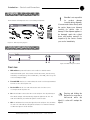
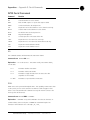
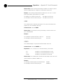
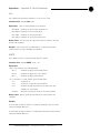
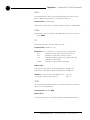
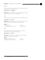
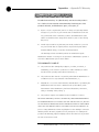
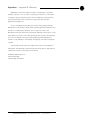
1
AP10 Telephone Interface
Installation & Operation Manual
ii
© 2002 ClearOne Communications, Inc. All
rights reserved. No part of this document may
be reproduced in any form or by any means
without written permission from ClearOne
Communications, Inc. Printed in the United
States of America. ClearOne Communications
reserves specific privileges. Information in this
document is subject to change without notice.
AP10 Installation and Operation
Manual
ClearOne Part No. 800-150-201
June 2002 (Rev. 2.0)
Technical Services Group ~ 1-800-283-5936 (USA) ~ 1-801-974-3760
iii
AP10 Installation and Operation Manual
Table of Contents
CHAPTER 1: Introduction
. . . . . . . . . . . . . . . . . . . . . . . .1
Features . . . . . . . . . . . . . . . . . . . . . . . . . . . . . . . . . . . . . . . . . . . . . . . . .1
Professional Services Group . . . . . . . . . . . . . . . . . . . . . . . . . . . . . . . . . . .2
Product registration . . . . . . . . . . . . . . . . . . . . . . . . . . . . . . . . . . . .2
Product returns . . . . . . . . . . . . . . . . . . . . . . . . . . . . . . . . . . . . . . . . .2
Unpacking . . . . . . . . . . . . . . . . . . . . . . . . . . . . . . . . . . . . . . . . . . . . . . . .3
Controls and Connections . . . . . . . . . . . . . . . . . . . . . . . . . . . . . . . . . . . . .3
Front view
. . . . . . . . . . . . . . . . . . . . . . . . . . . . . . . . . . . . . . . . . .3
Rear view . . . . . . . . . . . . . . . . . . . . . . . . . . . . . . . . . . . . . . . . . . .4
Before You Install . . . . . . . . . . . . . . . . . . . . . . . . . . . . . . . . . . . . . . . . . . .5
Power requirements . . . . . . . . . . . . . . . . . . . . . . . . . . . . . . . . . . . .5
Telephone line requirements . . . . . . . . . . . . . . . . . . . . . . . . . . . . . .5
Equipment placement . . . . . . . . . . . . . . . . . . . . . . . . . . . . . . . . . . .5
Environmental requirements . . . . . . . . . . . . . . . . . . . . . . . . . . . . . .5
CHAPTER 2: Installation . . . . . . . . . . . . . . . . . . . . . . . . . .7
Hardware Setup . . . . . . . . . . . . . . . . . . . . . . . . . . . . . . . . . . . . . . . . . . . .7
Connect the unit
. . . . . . . . . . . . . . . . . . . . . . . . . . . . . . . . . . . . . .7
Creating a G-Link network . . . . . . . . . . . . . . . . . . . . . . . . . . . . . . .8
Assigning device ID numbers
Connecting power
. . . . . . . . . . . . . . . . . . . . . . . . . . . . .9
. . . . . . . . . . . . . . . . . . . . . . . . . . . . . . . . . . . . .10
CHAPTER 3: Configuration . . . . . . . . . . . . . . . . . . . . . . . .11
DIP Switch Settings . . . . . . . . . . . . . . . . . . . . . . . . . . . . . . . . . . . . . . . . .11
Noise Burst/Auto-Adapt . . . . . . . . . . . . . . . . . . . . . . . . . . . . . . . . .11
Receive Boost . . . . . . . . . . . . . . . . . . . . . . . . . . . . . . . . . . . . . . . .11
Receive AGC . . . . . . . . . . . . . . . . . . . . . . . . . . . . . . . . . . . . . . . . .12
Auto-Answer . . . . . . . . . . . . . . . . . . . . . . . . . . . . . . . . . . . . . . . . .12
Auto-Disconnect
. . . . . . . . . . . . . . . . . . . . . . . . . . . . . . . . . . . . . .12
Call Progression/Loop
. . . . . . . . . . . . . . . . . . . . . . . . . . . . . . . . . .12
Technical Services Group ~ 1-800-283-5936 (USA) ~ 1-801-974-3760
iv
Receive Reduction . . . . . . . . . . . . . . . . . . . . . . . . . . . . . . . . . . . . .13
Calibration . . . . . . . . . . . . . . . . . . . . . . . . . . . . . . . . . . . . . . . . . . . . . . . .13
Noise Burst Adapt . . . . . . . . . . . . . . . . . . . . . . . . . . . . . . . . . . . . .13
Auto-Adapt . . . . . . . . . . . . . . . . . . . . . . . . . . . . . . . . . . . . . . . . . .14
Transmit level adjustment . . . . . . . . . . . . . . . . . . . . . . . . . . . . . . . .14
Receive level adjustment . . . . . . . . . . . . . . . . . . . . . . . . . . . . . . . . .14
CHAPTER 4: Operation
. . . . . . . . . . . . . . . . . . . . . . . . . .15
Using the AP10 . . . . . . . . . . . . . . . . . . . . . . . . . . . . . . . . . . . . . . . . . . . .15
To answer a call
. . . . . . . . . . . . . . . . . . . . . . . . . . . . . . . . . . . . . .15
To make and disconnect a call . . . . . . . . . . . . . . . . . . . . . . . . . . . . .15
Using the Telco Interface . . . . . . . . . . . . . . . . . . . . . . . . . . . . . . . . . . . . .16
To make and disconnect a call . . . . . . . . . . . . . . . . . . . . . . . . . . . . .16
To mute
. . . . . . . . . . . . . . . . . . . . . . . . . . . . . . . . . . . . . . . . . . . .17
Other telco options . . . . . . . . . . . . . . . . . . . . . . . . . . . . . . . . . . . . .17
Controllers . . . . . . . . . . . . . . . . . . . . . . . . . . . . . . . . . . . . . . . . . . . . . . . .17
Custom control through DB-25 port
. . . . . . . . . . . . . . . . . . . . . . . .17
Touch panel control . . . . . . . . . . . . . . . . . . . . . . . . . . . . . . . . . . . .17
APPENDICES . . . . . . . . . . . . . . . . . . . . . . . . . . . . . . . . .19
Appendix A: Specifications . . . . . . . . . . . . . . . . . . . . . . . . . . . . . . . . . . . .19
Appendix B: Pinouts . . . . . . . . . . . . . . . . . . . . . . . . . . . . . . . . . . . . . . . . .20
Appendix C: Serial Commands . . . . . . . . . . . . . . . . . . . . . . . . . . . . . . . . .21
Appendix D: Warranty . . . . . . . . . . . . . . . . . . . . . . . . . . . . . . . . . . . . . . .28
Appendix E: Compliance . . . . . . . . . . . . . . . . . . . . . . . . . . . . . . . . . . . . . .30
Appendix F: Block Diagram . . . . . . . . . . . . . . . . . . . . . . . . . . . . . . . . . . .32
Glossary . . . . . . . . . . . . . . . . . . . . . . . . . . . . . . . . . . . . . . . . . . . . . . . . .33
Index . . . . . . . . . . . . . . . . . . . . . . . . . . . . . . . . . . . . . . . . . . . . . . . . . . . .35
Technical Services Group ~ 1-800-283-5936 (USA) ~ 1-801-974-3760
CHAPTER 1: Introduction
Congratulations on purchasing the Audio Perfect® telephone interface. The AP10
uses advanced digital technology to maintain the highest possible audio quality. The
AP10 is designed as an accessory to the AP800 (echo cancelling, audio processing,
microphone mixing matrix) and enables the AP800 to connect to a standard
telephone line.
The AP10 is a single-line digital hybrid which uses digital signal processing
(DSP) to separate the transmit and receive audio—eliminating distortion, weak
signals, and feedback. It continually filters low and high frequency noise to provide
pure sound.
Features
•
Easy to install and operate
•
DTMF dialing capability
•
Simultaneous two-wire/four-wire operation within an Audio Perfect
system
•
G-Link network interconnection with up to eight AP800s and 16 AP10s
•
9.6kHz sampling rate allows continual adaptation to telephone-line
conditions
•
Full-time telco echo cancellation with 26 millisecond tail time
•
Conference up to 16 callers (with 16 AP10s) within an Audio Perfect system
•
Digital anti-alias filter minimizes hum and Central Office switching noise
•
Remote On/Off control via serial commands or rear-panel connection
•
Digital send filter/limiter for telephone line noise reduction
•
Compatible with any analog telephone system
•
No outside RF interference will affect performance
Technical Services Group ~ 1-800-283-5936 (USA) ~ 1-801-974-3760
Introduction ~ Unpacking
2
Professional Services Group
If you need additional information on how to install, set up, or operate your system,
please contact us at one of the locations listed below. We welcome and encourage
your comments so we can continue to improve our products and serve your needs.
ClearOne Communications ~ 1825 Research Way ~ Salt Lake City, UT 84119
Technical Support
Telephone:
1.800.283.5936 (USA) or 1.801.974.3760
Fax:
1.801.977.0087
E-mail:
[email protected]
Web site:
www.clearone.com
Sales and Customer Service
Telephone:
1.800.945.7730 (USA) or 1.801.975.7200
Fax:
1.800.933.5107 (USA) or 1.801.977.0087
E-mail:
[email protected]
ClearOne Communications EuMEA GmbH
Leonhardstr. 16-18, D-90443 Nuremberg, Germany
Telephone:
+49 911 955159-0
Fax:
+49 911 955159-10
E-mail:
[email protected]
Product registration
Please register your AP10 online by visiting ClearOne Technical Support at
www.clearone.com. When your product is properly registered, ClearOne
Communications is better able to serve you should you require technical assistance.
Registration information is also used to notify you of upgrades and new product
information.
Product returns
All product returns require a return authorization (RA) number. Please contact the
Technical Services Group before attempting to return your AP10 unit.
Technical Services Group ~ 1-800-283-5936 (USA) ~ 1-801-974-3760
3
Introduction ~ Controls and Connections
Unpacking
ClearOne is not responsible
for
product
damage
incurred during shipment.
You must make claims directly with
the carrier. Inspect your shipment
carefully for obvious signs of
damage. If the shipment appears to
be damaged, retain the original
boxes and packing material for
inspection by the carrier. Contact
your carrier immediately.
!
Ensure that the following items were received with your shipment:
Figure 1.1. AP10 unpacking diagram
Controls and Connections
A
B C
D
E
Figure 1.2. AP10 front panel controls
Front view
A. DIP switches. Operational features can be enabled or disabled via DIP
switches behind this panel. These features include auto-answer, auto-disconnect,
momentary or latching mode, device identification, caller AGC, caller boost, and
noise burst adapt/self adapt.
B. Transmit LED. This bicolor LED indicates the audio levels being transmitted
from the room to the telephone line.
C.
Receive LED. This bicolor LED indicates the audio level the room is
receiving from the telephone line.
D. On. The On button connects the AP10 to the telephone line (dependent upon
DIP switch settings) and automatically adapts the hybrid to the line. The
LED will illuminate green when the hybrid is in the On state.
E. Off. The Off button disconnects the hybrid from the telephone line and mutes
all audio. The LED indicates the hybrid’s Off state. The LED will illuminate
red when the hybrid is in the Off state.
Technical Services Group ~ 1-800-283-5936 (USA) ~ 1-801-974-3760
✍
Pressing and
On button for
half-second
hybrid is active will
hybrid.
holding the
more than a
while the
readapt the
4
Introduction ~ Controls and Connections
A
C
B
D
E
F G
Figure 1.3. AP10 rear-panel connectors
Rear view
A. Power. The AC power cord input is a NEMA-type connector allowing
100–240VAC, 50/60Hz.
B. G-Link In, Out. This RJ-45 connector is used to connect the AP10 to the
AP800 for control. AP-Ware is capable of accessing and controlling a
G-Link local area network (LAN) of up to eight AP800/AP400 units and
16 AP10 units. G-Link supports a distance of up to 20 feet between each
connected unit.
C.
Remote. This DB-25 connector provides control and status of the AP10 and
unbalanced audio. See Appendix B for pinouts.
D. Transmit Input. This Phoenix connector is used to connect transmit audio
(input) from the AP800 to the AP10, which is then sent to the telephone
line.
E. Receive Output. This Phoenix connector is used to connect receive audio
(telephone participant audio) from the AP10 to the AP800.
F.
Telco Line. This RJ-11 connector provides connection of a standard analog
telephone line to the hybrid.
G. Telco Set. This RJ-11 connector allows connection to a standard telephone
set. Tip and ring from the phone line are present at this connector when the
hybrid is in its off state. Tip and ring from the phone line are not present at
this point when the hybrid is in its on state.
Technical Services Group ~ 1-800-283-5936 (USA) ~ 1-801-974-3760
Introduction ~ Before You Install
Before You Install
Power requirements
The AP10 automatically accommodates voltage requirements of 100–240VAC,
50/60Hz, 15W.
Telephone line requirements
The AP10 model operates on a standard analog telephone line and connects to the
telephone system with a standard RJ-11C modular jack. If you do not have an
RJ-11C jack where you want to install your AP10, call your telephone company for
installation.
Equipment placement
The AP10 models are designed for installation in a standard 19-inch equipment
rack. You can also purchase side panels for desktop placement.
Environmental requirements
The AP10 can be safely operated in a room with varying temperatures between
32°F (0°C) and 100°F (38°C).
Technical Services Group ~ 1-800-283-5936 (USA) ~ 1-801-974-3760
5
6
Technical Services Group ~ 1-800-283-5936 (USA) ~ 1-801-974-3760
CHAPTER 2: Installation
The AP10 is designed for easy installation and set-up. All connections are made
through rear-panel connectors. This section provides instructions on installing the
units in the rack and making initial connections, creating a G-Link network, and
assigning device ID numbers.
The diagram below illustrates the typical connections that are made when
adding an AP10 to an AP800.
Microphones
AP800
Touch panel
controller
Inputs
Line
G-Link connection
Receive
Output
AP10
Telephone set
(optional)
Transmit
Input
Figure 2.1. System diagram
Hardware Setup
Connect the unit
Refer to the rear-panel drawing in Figure 2.2 on the following page. Each connector
is numbered for easy identification.
1.
Place the unit in the rack and attach it securely. AP10 models are designed
for installation in a standard 19-inch equipment rack.
2.
Connect your telephone line from the wall jack to the RJ-11C Line jack [F].
3.
Plug your telephone set into the RJ-11C Set jack [G].
4.
If you are using a custom controller for control and hybrid status, plug it
into the DB-25 Remote connector [C].
Technical Services Group ~ 1-800-283-5936 (USA) ~ 1-801-974-3760
8
Installation ~ Hardware Setup
A
C
B
D
E
F G
Figure 2.2. AP10 rear panel connectors
5.
✍
The three terminals in
the Phoenix connector
correspond with the backpanel audio contacts (from left to
right): +(positive), –(negative), and
(ground).
+
Wire the AP10 to the AP800 using the provided three-terminal Phoenix
push-on connectors. These connectors are designed for easy wiring; simply
insert the desired wire into the appropriate connector opening and tighten
down the top screw.
•
Transmit Input Audio connected to the Transmit Input [D] will be sent
down the telephone line.
•
–
Receive Output Audio from the telephone participant is passed to
Receive Output [E].
Creating a G-Link network
Ground
1.
Negative
Place the AP units in their proper locations. The back-panel G-Link In and
G-Link Out [B] connectors are designed for setting up your G-Link network.
G-Link connections between AP units are connected in daisy-chain fashion
Positive
using category five twisted-pair cable.
Figure 2.3. Phoenix push-on connector
2.
The first ClearOne unit in the chain must have the G-Link In connector
terminated with a G-Link terminator (provided).
AP800
AP 10
G-Link
Terminator
G-Link
AP 10
Audio: Transmit and Receive
G-Link
G-Link
Terminator
Figure 2.4. G-Link connection block diagram
3.
The first ClearOne unit’s G-Link Out connector is then attached to the
G-Link In connector on the next unit in the chain. At the end of the network,
the final unit must have the G-Link Out connector terminated with a G-Link
terminator as well.
A G-Link network will allow interconnection of up to 16 AP10s and eight AP800s.
If the AP units are stacked vertically, connect them using the short RJ-45 jumper
(provided). If networking over longer distances (up to 20 feet/ 6.1 meters between
units), use Cat 5 twisted-pair (10BaseT LAN) cable.
Technical Services Group ~ 1-800-283-5936 (USA) ~ 1-801-974-3760
9
Installation ~ Hardware Setup
Assigning device ID numbers
Once your physical G-Link network is established, you need to set up unique G-Link
device ID numbers for each AP10 on the network. As shipped from the factory, all
AP10 units default as binary address 0. Set device ID numbers for each AP10 unit
at your site by manipulating front-panel DIP switches 9–12, selecting/deselecting
If more than one AP10 is
assigned the same device
ID number, the Transmit
and Receive LEDs will flash red and
green on the affected units until the
error is corrected.
!
each switch to set up address 0–15 in binary code. Use the table below to determine
the proper DIP switch settings for the device ID you want to assign.
Device ID DIP switch settings
Binary
Address
0
1
2
3
4
5
6
7
8
9
10 (A)
11 (B)
12 (C)
13 (D)
14 (E)
15 (F)
DIP Switch 9
Position
0 (DOWN)
0 (DOWN)
0 (DOWN)
0 (DOWN)
0 (DOWN)
0 (DOWN)
0 (DOWN)
0 (DOWN)
1 (UP)
1 (UP)
1 (UP)
1 (UP)
1 (UP)
1 (UP)
1 (UP)
1 (UP)
DIP Switch 10
Position
0 (DOWN)
0 (DOWN)
0 (DOWN)
0 (DOWN)
1 (UP)
1 (UP)
1 (UP)
1 (UP)
0 (DOWN)
0 (DOWN)
0 (DOWN)
0 (DOWN)
1 (UP)
1 (UP)
1 (UP)
1 (UP)
DIP Switch 11
Position
0 (DOWN)
0 (DOWN)
1 (UP)
1 (UP)
0 (DOWN)
0 (DOWN)
1 (UP)
1 (UP)
0 (DOWN)
0 (DOWN)
1 (UP)
1 (UP)
0 (DOWN)
0 (DOWN)
1 (UP)
1 (UP)
DIP Switch 12
Position
0 (DOWN)
1 (UP)
0 (DOWN)
1 (UP)
0 (DOWN)
1 (UP)
0 (DOWN)
1 (UP)
0 (DOWN)
1 (UP)
0 (DOWN)
1 (UP)
0 (DOWN)
1 (UP)
0 (DOWN)
1 (UP)
Connecting power
The power input [1] will operate at any level between 100–240VAC, 50–60Hz, 15W
(typical). Plug in the AP10 to complete the hardware installation.
Technical Services Group ~ 1-800-283-5936 (USA) ~ 1-801-974-3760
10
Technical Services Group ~ 1-800-283-5936 (USA) ~ 1-801-974-3760
CHAPTER 3: Configuration
DIP Switch Settings
The AP10 has a variety of operational features configurable through DIP switch
settings, including noise burst/auto-adapt, receive AGC control, auto-answer, autodisconnect, call progression/loop, receive reduction, and hook-flash duration. Default
settings (as shipped from the factory) are denoted by an asterisk “*”.
Figure 3.1. AP10 DIP switches
Noise burst/auto-adapt
In some applications, you might want to adapt the hybrid with a white noise burst,
rather than allow the hybrid to adapt automatically to line conditions. To enable this
feature, set DIP switch 1 to the On position.
DIP Switch
Position
Description
1
On (up)
Burst adapt
1*
Off (down)
Auto-adapt
Receive boost
If incoming caller audio is consistently low, activate the Receive Boost. This will
increase receive audio by 6dB. To enable this feature, set DIP switch 2 to the On
position.
DIP Switch
Position
Description
2
On (up)
6dB Receive audio boost enabled
2*
Off (down)
6dB Receive audio boost disabled
Technical Services Group ~ 1-800-283-5936 (USA) ~ 1-801-974-3760
12
Configuration ~ DIP Switch Settings
Receive AGC
DIP switch 3 enables/disables the automatic gain control (AGC) function in the
firmware. The AGC feature is designed to keep soft and loud telephone participants
at a consistent level.
DIP Switch
Position
Description
3*
On (up)
Receive AGC enabled
3
Off (down)
Receive AGC disabled
Auto-answer
✍
To issue the AA (autoanswer) serial command to
toggle auto-answer, DIP
switch 4 must be off (down).
DIP switch 4 enables/disables auto-answer. When enabled, the AP10 will
automatically answer incoming calls after one complete valid ring has been detected.
DIP Switch
Position
Description
4
On (up)
Auto-answer enabled
4*
Off (down)
Auto-answer disabled (follows
the serial command)
Auto-disconnect
DIP switch 5 enables/disables auto-disconnect.
DIP Switch
Position
Description
5*
On (up)
Auto-disconnect enabled
5
Off (down)
Auto-disconnect disabled
Call progression/loop
In order for the settings on
DIP Switch 6 to function,
DIP Switch 5 must be on
(up). Auto-disconnect must be
enabled
before
either
Call
Progression or Loop Drop are
applicable.
✍
DIP switch 6 selects either loop drop or call-progress mode. Call-progress mode will
disconnect the line upon detection of a valid call-progress signal. Call progress will
detect the reorder tone and busy signal for the U.S., Canada, United Kingdom,
France, and Germany.
DIP Switch
Position
Description
6
On (up)
Call progression enabled
6*
Off (down)
Loop drop enabled
Technical Services Group ~ 1-800-283-5936 (USA) ~ 1-801-974-3760
13
Configuration ~ Calibration
Receive reduction
In some applications, it might be necessary to duck (lower) the receive audio coming
in through the telephone line when transmit audio is present. To enable receive
reduction, set DIP switch 7 to the On position.
DIP Switch
Position
Description
7
On (up)
Receive reduction enabled
7*
Off (down)
Receive reduction disabled
Calibration
The following information will help you make adjustments to optimize your system
performance. Verify all components and all connections. Ensure that proper power is
supplied to the AP10 and that the unit is off (indicated by the red Off LED). If the
green On LED is lit, press the Off button [E].
A
B C
D
E
Figure 3.2. AP10 front-panel controls
There are two calibration methods for the AP10: noise burst and auto-adapt.
Which procedure is used depends on whether you have DIP switch 1 on (up) for
noise-burst adapt, or DIP switch 1 Off (down) for auto-adapt. Either will suffice to
calibrate the AP10. The difference is the application and/or personal preference.
Some applications are not suited for a .75-second noise burst, and might require
the gradual adaptation over time.
Noise burst adapt
If DIP switch 1 is on (up), have someone call the AP10 from another location.
Answer the line by pressing the On button [D]. (If the auto-answer feature is active,
the unit will answer the call after one complete ring.)
The caller will hear a short white noise burst (it will sound like static) and a
short beep. This automatically adapts the AP10 to the telephone line.
Technical Services Group ~ 1-800-283-5936 (USA) ~ 1-801-974-3760
✍
Some echo and ringing
might be heard while
calibrating the AP10.
Disregard it and continue with
calibration until the end of the
procedure. The echo and ringing
will disappear.
14
Configuration ~ Calibration
Auto-adapt
If DIP switch 1 is off (down), call someone and continue to talk while the system
gradually adapts over time. Once complete, the AP10 will be fully calibrated and
ready for use. Press the Off button [E]. If the auto-disconnect feature is active, and
the caller hangs up, the AP10 will disconnect upon sensing loop drop or callprogress tones, depending on the position of DIP switch 6.
Transmit level adjustment
Someone in the local room should speak into the microphone at a normal distance,
AP10 transmit and receive
audio level adjustments
are made using the
AP800. Nominal transmit and
receive level for the AP10 is 0dBu.
✍
in a normal voice. The party at the distant location should not speak during the
transmit adjustment. Adjust the AP800 output that is connected to the AP10
Transmit input to 0dB. The AP10 Transmit LED [B] should illuminate solid green
while the person is speaking and extinguish when the person stops.
Receive level adjustment
Someone in the distant location should speak into the microphone at a normal
distance, in a normal voice; the local room should maintain silence. Adjust the
AP800 input that is connected to the AP10 Receive output to 0dB. The AP10
Receive LED [C] should be solid green while the person is speaking and extinguish
when the person stops.
Technical Services Group ~ 1-800-283-5936 (USA) ~ 1-801-974-3760
CHAPTER 4: Operation
The AP10 has four basic functions: make a call, answer a call, disconnect a call, and
mute. This chapter explains how to perform these functions with the AP10 unit and
a telephone handset (optional) and with the Telco interface in AP-Ware. You can also
use touch panels and custom control devices.
Using the AP10
A
B C
To answer a call
D
E
Figure 4.1. AP10 front panel controls
Depending on how you have configured your AP10, an incoming call can ring on the
telephone set connected to the AP10, the receive output, and pass a serial ring to the
control device. An incoming call will also cause the front panel On LED to flash. You
can answer the call in one of two ways:
•
Press the On button [D] on either the front panel or from your remote
control. This will route the call through the AP10 to the AP800. The green
✍
If auto-answer is enabled
(DIP switch 4), the AP10
will answer after the first
complete ring.
On LED will light. The red Off LED will extinguish.
– or –
•
Answer the call by picking up the telephone handset and talking to your
party over the telephone.
To make and disconnect a call
1.
Call the party using your handset.
2.
After the other party has answered, route the call through the AP10 by
pressing the On button [D]. The On LED will light and the AP10 will take
control of the call, disabling the telephone set. You can now safely hang up
the handset without disconnecting your call.
If using an external controller, it is not necessary to press the On button
[D]. The DIAL serial command automatically engages the AP10. See Serial
Commands, page 22.
Technical Services Group ~ 1-800-283-5936 (USA) ~ 1-801-974-3760
✍
If auto-disconnect is
enabled (DIP switch 5),
the AP10 will disconnect
upon sensing loop drop or callprogress tones (depending on the
position of DIP switch 6).
16
Operation ~ Using the Telco Interface
3.
When the conversation is complete, press the Off button [E] to disconnect
the call. You can also disconnect using an external controller. If the handset
is off hook, audio will be routed to the telephone.
If your call is through the handset only (the red Off LED will be lit), hang up
when the conversation is complete.
Using the Telco Interface
To make and disconnect a call
1.
Open AP-Ware and select the AP10 unit.
2.
Click the AP10 Telco button on the Flow Screen to open the Telco interface.
Detailed instructions on
creating site files and
using AP-Ware can be
found in the AP-Ware help file.
✍
Figure 4.2. Telco dialing interface
3.
4.
Activate the telephone interface by clicking On or by beginning to dial.
When the green light below the On button illuminates, enter the number to
be dialed, including any dial-out prefixes.
5.
Click Send. If you clicked directly on the number buttons, the call will be
completed as you finish dialing—just like using a standard telephone.
6.
When you are finished with the call, click Disconnect to end the call.
Technical Services Group ~ 1-800-283-5936 (USA) ~ 1-801-974-3760
Operation ~ Controllers
To mute
•
Click Mute TX to mute the transmit audio (audio sent to the telephone line).
•
Click Mute RX to mute the receive audio (audio from the telephone line).
Other telco options
•
Hook-Flash. This button sends a momentary interruption in line seizure to
the telephone line.
•
Re-Null. This feature sends a short noise burst down the telephone line and
forces the AP10 to adapt to the telephone line.
•
Auto-Answer. This button turns auto-answer on and off. If auto-answer is
turned on, the AP10 answers the call after the first complete ring. If it is
turned off, you will need to manually answer the call. You must have DIP
switch 4 in the on (up) position.
Controllers
Custom control through DB-25 port
A customer-supplied remote control or contact-closure switch can be programmed to
perform functions such as: mute on/off, system on, and system off. For pinouts, see
Remote connector pinout, page 20.
Touch panel control
The AP products are designed to function with touch panel control systems. The
controller is connected to the AP800 RS-232 port. Through the G-Link network, all
networked AP products can be accessed and controlled from that single point.
Using a touch panel, you can control the following: AP10 on or off control;
transmit and receive audio mute; DTMF tone generation; volume control for
receive audio; query of the AP10’s binary address; re-nulling the telephone hybrid;
metering of input and output, and ERL and ERLE. These commands are also
available in the AP-Ware software, which communicates with the AP10 via an
AP800 RS-232 serial port and the G-Link network.
Technical Services Group ~ 1-800-283-5936 (USA) ~ 1-801-974-3760
17
18
Technical Services Group ~ 1-800-283-5936 (USA) ~ 1-801-974-3760
APPENDICES
Appendix A: Specifications
Dimensions (LxDxH)
17.25" x 10.25" x 1.75"
43.8 x 26 x 4.5 cm
Weight
7.5 lb/3.4 kg dry
12.6 lb/5.7 kg shipping
Operating Temperature
32–100° F
0–38° C
Humidity
0% to 80%, non-condensing
Power Input Range
Auto-adjusting
100–240VAC; 50/60Hz
Power Consumption
8W typical
Front Panel DIP Switches
Device Identification:
4-position DIP switch
Receive AGC
Auto-Answer
Auto-Disconnect
Self-Adapt
Disconnect on Loop or Loop and
Call Progression
Noise Burst Adapt
Momentary On/Off
Latching On/Off
G-Link In/Out
Proprietary Network
RJ-45 (2), 38.4kbps,
110kΩ impedance
Category five twisted-pair cable
20' (6.1 meters) maximum cable
length between two networked
devices
Control/Status
DB-25 female
Inputs: active low (pull to ground)
Outputs: Open collector, 40VDC
max, 40mA each
Unbalanced Transmit and Receive
Telco Line
RJ-11
POTS (plain old telephone service)
or analog extension from a PBX
A-lead supervision provided
Telco Set
RJ-11
Connect analog telephone set
A-lead supervision provided
Transmit Input
Push-on terminal block,
balanced, bridging
Impedance: >20kΩ
Nominal Level: 0dBu
Maximum Level: 20dBu
Technical Services Group ~ 1-800-283-5936 (USA) ~ 1-801-974-3760
Receive Output
Push-on terminal block, balanced
Impedance: <50Ω
Nominal Level: 0dBu
Maximum Level: 20dBu
Audio Performance
Conditions: Unless otherwise
specified, all measurements are
performed with a 250Hz to 3.5kHz
BW limit (no weighting). Reference
to 0dBu at -15dBm on/off the
telephone line (Receive AGC
disabled).
Frequency Response: 250Hz to
3.5kHz, ±1dB
SNR: >56dB
THD+N: <0.3%
Telco Echo Cancellation
TEC tail time: 31ms
TEC null: 55dB nominal
Approvals
FCC, CSA, CE
Set-up Software
AP-Ware
20
Appendices ~ Appendix B: Pinouts
Appendix B: Pinouts
13
25
Figure B.1. Remote Port
1
14
Remote connector pinout
Pin
Description
1
Remote On*
2
Remote Off*
3
N/C
4
N/C
5
Switch/Indicator Common
6
N/C
7
N/C
8
N/C
9
Unbalanced Transmit Audio Input (0dBu nominal)
10
Unbalanced Receive Audio Input (0dBu nominal)
11
NC
12
N/C
13
Audio Common
14
On indication**
15
Off indication**
16
N/C
17
N/C
18
Switch Indicator Common
19
Transmit Presence Indicator**
20
Receive Presence Indicator**
21
Switch Indicator Common
22
Audio Common
23
Audio Common
24
Audio Common
25
Switch Indicator Common
*
Remote control provided via contact closure to Switch/Indicator Common
** Remote indicators provided via open collector outputs to Indicator Common
(<40V, <40mA)
Technical Services Group ~ 1-800-283-5936 (USA) ~ 1-801-974-3760
21
Appendices ~ Appendix B: Pinouts
Set connector pinout
Pin
Description
Pin
Description
1
To pin 6 of SET RJ-11C
4
Tip
2
To pin 5 of SET
5
To pin 2 of LINE
3
Ring
6
To pin 1 of LINE RJ-11C
Line connector pinout
Pin
Description
Pin
Description
1
To pin 6 of LINE RJ-11C
4
Ring
2
To pin 5 of LINE
5
To pin 2 of SET
3
Tip
6
To pin 1 of SET RJ-11C
Appendix C: Serial Commands
The AP10 accepts serial commands via the AP800’s serial port; the commands are
passed to the unit through the
G-Link network. The commands in this manual pertain only to the AP10. RS-232
serial port protocol is 9,600 (default), 19,200, or 38,400 baud; 8 bits, 1 stop bit,
no parity.
Conventions
The following typographic conventions are used in this document to describe the
different serial commands. Use the Command structure section and the examples as
a guide when creating your serial commands.
Technical Services Group ~ 1-800-283-5936 (USA) ~ 1-801-974-3760
22
Appendices ~ Appendix C: Serial Commands
Convention
Description
<X>
Parameters enclosed in < > indicate a mandatory parameter.
[X]
Parameters enclosed in [ ] indicate an optional parameter.
1-8
Parameters separated by a - indicate a range between the values.
4,7,9
Parameters separated by a , indicate a list of available values.
EREF
Words in uppercase bold indicate command text.
DEVICE
Indicates the device type and device number on the G-Link
network. It is composed of a device type number and a device
number. The device type for the AP10 is always 2 and the device
ID will always be 0–0–9, A–F (where A=10 and F=15), or * (to
select all AP10 units).
Command structure
Commands can be either UPPERCASE or lowercase. Also, extra spaces or tabs
between arguments in text commands is allowed. Return values are always in
uppercase. For a command to be recognized by the serial port, the command must be
terminated by a carriage return.
The structure of serial commands is as follows: #DEVICE COMMAND [X] [X]
#
indicates the start of a command line
DEVICE
represents the device type and device number
COMMAND
is the command text
[X] [X]
represents any additional options in the order that they appear in
the command descriptions that follow
Example
A command to enable auto-answer on the AP10 device “0” has the command line:
#20 AA 1 1. In this command line, 2=AP10, 0=unit 0, AA=command, 1=Telco
channel 1, 1=on state. If a command calls for a “null” value, leave a blank in the
command line. For example, “#20 AA” returns the current auto-answer state on
device 20.
For a command to be recognized by the serial port, it must be terminated by a
carriage return.
Technical Services Group ~ 1-800-283-5936 (USA) ~ 1-801-974-3760
Appendices ~ Appendix C: Serial Commands
AP10 Serial Commands
Command
Function
AA
Sets auto-answer for a telco channel
DIAL
Dials a DTMF sequence or reports last sequence dialed
HOOK
Sends a hook flash to the telephone line
LVL
Reports the level of the transmit or receive channel (read only)
MUTE
Sets the mute for the transmit or receive channel
NULL
Re-nulls the AP10 to the telephone line
RING
Ring acknowledgement
TE
Selects/reports the connect state of the unit
TERL
Reports the telco echo return loss (read only)
TERLE
Reports the telco echo return loss enhancement (read only)
UID
Reports the unit identification number
VER
Reports the current firmware version
AA
This command activates and deactivates the auto-answer feature.
Command form: DEVICE AA <X>
Explanation: <X> is the action (i.e. auto-answer enable, auto-answer disable,
current state)
X=0
Parameter disables auto-answer
X=1
Parameter enables auto-answer
X=2
Parameter to toggle the state from one state to the other
(regardless of current state)
X= Null
Parameter to report back the current state.
DIAL
DTMF tones can be generated through the AP10. This capability remains active after
a call is placed, so tones can be issued for use with voice mail and pagers. If the
AP10 is not connected when this command is issued, the unit will connect to the
line first, then dial the tone(s).
Command form: DEVICE DIAL <STRING>
Explanation: <STRING> is any valid combination of touch tone characters. A
comma indicates a two-second pause. STRING has a maximum length of 40
characters. Valid characters are: 0 through 9, #, * and ,
Technical Services Group ~ 1-800-283-5936 (USA) ~ 1-801-974-3760
23
24
Appendices ~ Appendix C: Serial Commands
Return values: DIAL returns the dialed string of numbers. The string is returned
after the command has been completed (i.e. dialed all the touch tones).
Example: The following command dials the number (801) 975-7200. A 9 and a
pause is generated to get an outside line on a PBX.
The number is to be dialed on device #20.
The following is returned out the serial port:
#20 DIAL 9,8019757200
#20 DIAL 9,8019757200
HOOK
This command sends a momentary interruption in line seizure (hook flash) to the
telephone line. This command is write-only.
Command form: DEVICE HOOK
Return values: If hook flash succeeded, the following is returned out the serial
port: DEVICE HOOK
Example:
The command to request hook flash on device 20:
The following is returned out the serial port:
#20 hook
#20 hook
HOOKD
This command changes or reports the hook flash duration of the unit.
Command form: DEVICE HOOKD <X>
Explanation: <X> is the action (i.e. hook flash duration, current state)
X=0
X=1
X=Null
Parameter to set hook flash duration to 50ms
Parameter to set hook flash duration to 500ms
Parameter to report back the current state.
Return values: The command will return the hook flash duration of the unit in the
same format as the command. HOOKD <X>
Example:
The following command requests hook flash duration:
The following is returned out the serial port:
HOOKD
HOOKD 4
Technical Services Group ~ 1-800-283-5936 (USA) ~ 1-801-974-3760
Appendices ~ Appendix C: Serial Commands
LVL
This command reports back the transmit or receive level for a unit.
Command form: DEVICE LVL <CH>
Explanation: <CH> is which parameter to be measured.
CH=RXIN
CH=RXOUT
CH=TXIN
CH=TXOUT
Parameter for level from the telephone line
Parameter for level from the AP10
Parameter for level into the AP10
Parameter for level to the telephone line
Return values: LVL will return the output level of the line channel in the same
format as the command.
Example: If the current level for RXIN channel is -20dBu, the following is
returned out the serial port: DEVICE LVL RXIN -20
MUTE
This command controls or reports the mute status of a channel.
Command form: DEVICE MUTE <CH> <X>
Explanation:
<CH> is the channel(s) to be muted/unmuted.
CH=T
Parameter to apply to the transmit channel
CH=R
Parameter to apply to the receive channel
CH=*
Parameter to apply to both channels
<X> is the action (i.e. mute, unmute, report the mute state).
X=0
Set mute to off
X=1
Set mute to on (mute the selected channel)
X=2
Parameter to toggle the state from one state to the other
(regardless of current state)
X=NULL
Report the current state of mute for the selected channel
Return values: MUTE returns the mute status in the same format as the
command.
Example:
If current state of mute for channel T is muted, the following is returned out the
serial port: DEVICE MUTE T 1
If current state of mute for channel T is unmuted, the following is returned out the
serial port: DEVICE MUTE T 0
Technical Services Group ~ 1-800-283-5936 (USA) ~ 1-801-974-3760
25
26
Appendices ~ Appendix C: Serial Commands
NULL
This command sends a short noise burst down the telephone line and forces the
AP10 to adapt to the telephone line. This command is write-only.
Command form: DEVICE NULL
Return Values: If the renull succeeded, the following is returned: DEVICE NULL
RING
When the AP10 receives a ring at the dialed-up location, the AP10 will respond:
Device RING
TE
Controls and reports the connection status of the unit.
Command form: DEVICE TE <X>
Explanation: <X> is the action (i.e., connect, disconnect, current state)
X=0
Parameter to set the unit to disconnect from the line
X=1
Parameter to set the unit to connect to the line
X=2
Parameter to toggle the state from one state to the other
(regardless of current state)
X=Null
Parameter to report back the current state
Return values:
If the current connect state is on, the following returns: DEVICE TE 1
If the current connect state if off, the following returns: DEVICE TE 0
Examples: To connect the unit to the telephone line:
To report the connection state of the unit:
#20 TE 1
#20 TE
TERL
This command reports back the telephone echo return loss (ERL) for the AP10 in
dB. This is a read-only parameter.
Command form: DEVICE TERL
Return values:
If the current TERL level is 10 dB, the following is returned: DEVICE TERL 10
Technical Services Group ~ 1-800-283-5936 (USA) ~ 1-801-974-3760
Appendices ~ Appendix C: Serial Commands
TERLE
This command reports back the telephone echo return loss enhancement (ERLE) for
the AP10 in dB. This is a read-only parameter.
Command form: DEVICE TERLE
Return values: If the current TERLE level for the telephone canceller is 20dB, the
following is returned out the serial port: DEVICE TERLE 20
UID
This command returns the unique ID number of the unit. This command is read-only.
Command form: DEVICE UID
Return values: UID returns the unit ID code. The Unit ID is composed of an eightdigit hex number (assigned at the factory) to uniquely identify the unit.
Example:
To request the unit ID:
The following is returned out the serial port:
#20 UID
#20 UID A4EF906C
VER
This command returns current version of firmware. This version is unique to a
released version of firmware. This command is read-only.
Command form: DEVICE VER
Return values: VER returns the version of firmware (a major version number
followed by a period and a minor version number).
Example:
To request the unit ID from device 20
The following is returned out the serial port:
#20 VER
#20 VER 1.1
Technical Services Group ~ 1-800-283-5936 (USA) ~ 1-801-974-3760
27
28
Appendices ~ Appendix D: Warranty
Appendix D: Warranty
ClearOne Communications, Inc. (Manufacturer) warrants that this product is
free of defects in both materials and workmanship. Should any part of this
product be defective, the Manufacturer agrees, at its option, to:
A. Repair or replace any defective part free of charge (except transportation
charges) for a period of one year from the date of installation for the enduser, provided the owner returns the product to the Manufacturer at the
address set forth below. No charge will be made for parts or labor during
this period;
B. Furnish replacement for any defective parts in the product for a period of
one year from the date of original purchase. Replacement parts shall be
furnished without charge, except labor and transportation.
This Warranty excludes assembled products not manufactured by the
Manufacturer whether or not they are incorporated in a Manufacturer product or
sold under a Manufacturer part or model number.
THIS WARRANTY IS VOID IF:
A. The product has been damaged by negligence, accident, act of God, or
mishandling, or has not been operated in accordance with the procedures
described in the operating and technical instructions; or,
B. The product has been altered or repaired by other than the Manufacturer or
an authorized service representative of the Manufacturer; or,
C.
Adaptations or accessories other than those manufactured or provided by the
Manufacturer have been made or attached to the product which, in the
determination of the Manufacturer, shall have affected the performance,
safety or reliability of the product; or,
D. The product’s original serial number has been modified or removed.
NO OTHER WARRANTY, EXPRESS OR IMPLIED, INCLUDING WARRANTIES
OF MERCHANTABILITY OR FITNESS FOR ANY PARTICULAR USE, APPLIES
TO THE PRODUCT. MANUFACTURER’S MAXIMUM LIABILITY HEREUNDER
SHALL BE THE AMOUNT PAID BY THE END-USER FOR THE PRODUCT. No
person or entity authorized to assume any obligation or other liability in connection
with the products. No action, regardless of form, arising out of or relating to the
product or this Warranty, may be brought by end-user more than one (1) year after
the cause of action has accrued.
Technical Services Group ~ 1-800-283-5936 (USA) ~ 1-801-974-3760
Appendices ~ Appendix D: Warranty
Manufacturer shall not be liable for punitive, consequential, or incidental
damages, expenses, or loss of revenue or property, inconvenience, or interruption
in operation experienced by the end user due to a malfunction in the purchased
product. No warranty service performed on any product shall extend the
applicable warranty period.
In case of unsatisfactory operation, the end-user shall promptly notify the
Manufacturer at the address set forth below in writing, giving full particulars as to
the defects or unsatisfactory operation. Upon receipt of such notice, the
Manufacturer will give instructions respecting the shipment of the product, or such
other matters as it elects to honor this warranty as above provided. This warranty
does not cover damage to the product during shipping and the Manufacturer
assumes no responsibility for such damage. All shipping costs shall be paid by the
customer.
This warranty extends only to the original end user and is not assignable or
transferable. This Warranty is governed by the laws of the State of Utah, without
regard to the conflicts of interests provisions thereof.
ClearOne Communications, Inc.
1825 Research Way
Salt Lake City, Utah 84119
Technical Services Group ~ 1-800-283-5936 (USA) ~ 1-801-974-3760
29
30
Appendices ~ Appendix E: Compliance
Appendix E: Compliance
FCC Part 15 Compliance
This equipment has been tested and found to comply with the limits for a Class A
digital device, pursuant to Part 15 of the FCC rules. These limits are designed to
provide reasonable protection against harmful interference when the equipment is
operated in a commercial environment. This equipment generates, uses, and can
radiate radio frequency energy and, if not installed and used in accordance with the
instruction manual, may cause harmful interference to radio communications.
Operation of this equipment in a residential area is likely to cause harmful
interference, in which case the user will be required to correct the interference at
his/her own expense.
Changes or modifications not expressly approved by ClearOne
Communications, Inc. could void the user’s authority to operate the equipment.
FCC Part 68 Compliance
FCC Registration Number: FBIUSA-43110-BR-T
Ringer Equivalence Number (REN): 0.6B
A label containing, among other information, the FCC registration number and
Ringer Equivalence Number (REN) for this equipment is prominently posted on the
top plate, near the rear of the equipment. If requested, this information must be
provided to your telephone company.
USOC Jacks: This device uses RJ-11C and RJ21X terminal jacks.
The REN is used to determine the quantity of devices which may be connected to the
telephone line. Excessive RENs on the telephone line may result in the devices not
ringing in response to an incoming call. In most, but not all areas, the sum of the
RENs should not exceed five (5). To be certain of the number of devices that may be
connected to the line, as determined by the total RENs, contact the telephone
company to obtain the maximum RENs for the calling area.
If this equipment causes harm to the telephone network, the telephone
company will notify you in advance that temporary discontinuance of service may
be required. If advance notice is not practical, the telephone company will notify
the customer as soon as possible. Also, you will be advised of your right to file a
complaint with the FCC if you believe it is necessary.
The telephone company may make changes in its facilities, equipment,
operations, or procedures that could affect the operation of the equipment. If this
happens, the telephone company will provide advance notice for you to make the
necessary modifications in order to maintain uninterrupted service.
Technical Services Group ~ 1-800-283-5936 (USA) ~ 1-801-974-3760
Appendices ~ Appendix E: Compliance
If you experience problems with this equipment, contact ClearOne
Communications, Inc., 1825 Research Way, Salt Lake City, Utah 84119, or by
phone at (801) 975-7200 for repair and warranty information. If the trouble is
causing harm to the telephone network, the telephone company might request that
you remove the equipment from the network until the problem is resolved.
No user serviceable parts are contained in this product. If damage or
malfunction occurs, contact ClearOne Communications for instructions on its
repair or return.
This equipment cannot be used on telephone company provided coin service.
Connection to Party Line Service is subject to state tariffs.
IC Compliance
NOTICE: The Industry of Canada label identifies certified equipment. This
certification means that the equipment meets certain telecommunications network
protective operational and safety requirements. The Department does not guarantee
the equipment will operate to the user’s satisfaction.
Before installing this equipment, users should ensure that it is permissible to
be connected to the facilities of the local telecommunications company. The
equipment must also be installed using an acceptable method of connection. In
some cases, the company’s inside wiring associated with a single line individual
service may be extended by means of a certified connector assembly (telephone
extension cord). The customer should be aware that compliance with the above
conditions may not prevent degradation of service in some situations.
Repairs to certified equipment should be made by an authorized Canadian
maintenance facility designated by ClearOne Communications. Any repairs or
alterations made by the user to this equipment, or equipment malfunctions, may
give the telecommunications company cause to request the user to disconnect the
equipment.
Users should ensure for their own protection that the electrical ground
connections of the power utility, telephone lines and internal metallic water pipe
system, if present, are connected together. This precaution may be particularly
important in rural areas.
Ringer Equivalence Number (REN): 0.6B
IC Certification Number: 1970 11504 A
Safety Information
CAUTION: Users should not attempt to make such connections themselves, but
should contact the appropriate electrical inspection authority, or electrician, as
appropriate.
Technical Services Group ~ 1-800-283-5936 (USA) ~ 1-801-974-3760
31
32
Appendices ~ Appendix F: Block Diagram
Appendix F: Block Diagram
G–LINK
RS-485
CNVRT
Technical Services Group ~ 1-800-283-5936 (USA) ~ 1-801-974-3760
Glossary
Glossary
Acoustic Echo Cancellation (AEC) A process in which acoustical echo is
removed from a signal. AEC can be used to remove unwanted signals from mic audio
if the unwanted acoustic signal is available separately as an electronic signal.
Ambient Noise The existing room-level noise, such as that caused by ventilation
systems, paper shuffling, and background chatter.
Attenuation A reduction of signal amplitude.
Automatic Gain Control (AGC) Automatically increases or decreases audio gain
to maintain a consistent audio level.
Automatic Microphone Mixer A microphone mixer that automatically activates
and deactivates microphone channels. This serves to increase intelligibility of the
audio by reducing reverberation and noise picked up by the microphones.
Clipping A condition in which a signal level exceeds the maximum level a circuit
can handle. This is usually caused by overdriving an input. It always causes
distortion and typically leads to listener fatigue and accelerated failure of
loudspeaker drivers.
Digital Hybrid A telephone hybrid that uses digital signal processing to provide
excellent audio separation between the send and receive audio paths.
Distributed Echo Cancellation ClearOne’s proprietary system for applying echo
cancellation individually to each mic input. Used in AP800 and AP400 units.
Digital Signal Processor (DSP) A high speed digital numeric processor that can
rapidly calculate complex mathematical equations. The DSP is the most important
component used in ClearOne digital products.
Echo Cancellation The process in which acoustic echoes are canceled. This is
accomplished by sampling the distant audio that is amplified through the
loudspeaker in the room. When this audio is picked up by the microphone (this is
acoustic echo), an echo canceller eliminates or “cancels” the echo.
Four Wire Typically refers to audio in and out of a video codec.
G-Link A high speed digital network bus used to link AP800, AP400, and AP10
units.
Integrated Dialing The ability of a telephone hybrid to dial (generate touch tones)
via an RS-232 serial connection.
Technical Services Group ~ 1-800-283-5936 (USA) ~ 1-801-974-3760
33
34
Glossary
Matrix mixer A mixer that allows routing of any input or combination of inputs to
an output or any combination of outputs.
Omni-directional Microphone A microphone that picks up audio in a 360-degree
pattern.
Reverberation Audio in a room that bounces off a wall, ceiling, table or other
objects and then is picked up by microphone. High reverberation causes listener
fatigue and makes audio difficult to understand.
Simultaneous Two Wire/Four Wire The ability of a teleconferencing device to
connect to a video codec and a telephone line simultaneously.
Sound Pressure Level (SPL) The measure of acoustical audio in the air. Is
measured in dB using an SPL meter.
Telephone Hybrid A term used to refer to a telephone interface that separates
send and receive audio. Same as a digital hybrid.
Two Wire Typically refers to a telephone line.
Uni-directional Microphone A microphone that picks up audio in a directional
(usually 180 degrees or less) pattern.
Technical Services Group ~ 1-800-283-5936 (USA) ~ 1-801-974-3760
35
Index
Index
A
H
answer a call 15
hook-flash 17, 24
AP-Ware 15, 16
hook-flash duration 11, 24
AP10 3
connecting the unit 7
control 17
features 2
L
line connector 21
loop drop 11, 12, 14
front-panel controls 3
operation 15
rear-panel connectors 4
auto-adapt 11, 13, 14
auto-answer 3, 11, 12, 15, 17, 23
auto-disconnect 11, 12, 15
M
make a call 15, 16
meter 17
mute 15, 17, 25
N
C
calibration 13
call progression 11, 12, 14
control 17
noise burst 11, 13, 26
null 26
P
pinouts 17, 20
D
device ID 7, 9
dial 23
digital signal processing 1
DIP switches 3, 19
settings 11
power 4, 10, 19
Professional Services Group 1
R
re-null 17
disconnect a call 15, 16
receive AGC 11, 12
DTMF dialing 2, 17
receive boost 11
receive LED 3, 9
receive level 14, 25
E
ERL 17
ERLE 17
error 9
receive output 4, 8, 19
receive reduction 11, 13
registration 2
remote connector 8, 20
returns 2
F
frequency response 19
S
serial command 15, 22
G
set connector 21
G-Link In, Out 4, 8, 19
specifications 19
G-Link network 2, 7, 8
G-Link terminator 8
Technical Services Group ~ 1-800-283-5936 (USA) ~ 1-801-974-3760
36
Index
T
telco echo cancellation 2, 19
Telco interface 15, 16
telco line 4
telco set 4
TERL 26
TERLE 27
tip and ring 4
transmit input 4, 8, 19
transmit LED 3, 9
transmit level 14, 25
V
version 27
W
white noise 11, 13
Technical Services Group ~ 1-800-283-5936 (USA) ~ 1-801-974-3760