1
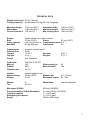
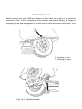
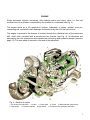
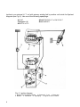
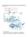
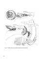
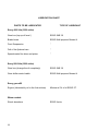
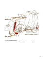
STABILIMENTO DI PONTEDERA UFFICIO TECNICO SERIE Dis. 88356 M 2 a EDIZIONE, 600016102 Printed in Italy Fig. 1 - Vespa 150 2 NOTICE To keep your VESPA in perfect running order and not to invalidate the guarantee offered by the contract, it is advisable to entrust repairs only to retailers or authorized service stations. Demand original Piaggio spare parts exclusively. All PIAGGIO spares are made of the same material, have undergone the same machining steps and inspections as the components of your VESPA. This means guarantee for long life and normal performance of your machine and for your personal safety. Special care should be taken with regard to fuel mixture which should consist of a good quality gasoline and oil of make, grade and in the amount prescribed in this booklet, page 21. INDEX Introductory note Technical data Identification data Engine Controls Frame Electric wiring Tool kit Accessories Operation Maintenance Lubrication chart Fault finding 4 5 6 7 12 13 16 19 19 21 26 32 35 3 The descriptions and illustrations in this booklet are not to be taken as binding on the Manufacturer. The essential features of the model described and illustrated herein remaining unaltered, the PIAGGIO Firm reserves therefore the right to carry out at any moment, without being obliged to bring this booklet up-todate in due course, modification that may occur concerning machine units and parts, or delivery of accessories, that the Firm deems to be convenient on improvement purposes or for what may concern manufacturing or commercial requirements. INTRODUCTORY NOTE The « Piaggio Co. » welcoming you in the family of the Vespa owners, wishes to thank you for your preference, trusting that this scooter will be to your satisfaction. For its characteristics (comfort, low fuel consumption, noiseless running, neatness etc.) the Vespa can have a large field of use: for work purpose as well as tourist trips, both along large highways and narrow farm roads. Long and hard rides will not worry you and, on driving the Vespa, you will soon realize its excellent performance. This booklet, in which the simple instructions for operation and maintenance can be found, will enable you to better know your Vespa and use it in the most suitable way. NOTE: This manual was copied from an original 1962 owner's manual. It was carefully restored by Scooterstation. This manual may be freely copied and passed on to others for sharing, as long as Scooterstation remains mentioned as the provider of this manual. Scooterstation is not liable for any damage incurred through the use of this manual be it physical or mechanical. This manual was created using the free office software OpenOffice. This software is obtainable for free at www.openoffice.org (c)2004 Scooterstation (www.scooterstation.com) 4 TECHNICAL DATA Weight (w/out fuel) 87 Kg (194 Lbs) Carrying capacity 2 persons and 10 Kg (22 Lbs) of luggage. Maximum length Wheel base Ground clearance 1745 mm (68.7") 1180 mm (46.4") 130 mm (5.1 ") Engine Bore Cubic capacity Max BHP single cylinder, air cooled 2-stroke 57 mm (2.24") Stroke 57 mm (2.24") 145.5 cc (8.88 cu in) Compression ration 6.5: 1 5.5 @ 5000 rpm Lubrication 2% Transmission Primary drive 1st gear 3rd gear Clutch 4 speed, constant mesh 22/67 13.35: 1 2nd gear 6.64: 1 4th gear wet, multiplate Carburetor Main jet Diffuser Throttle valve Dell'Orto SI 20/17C 100 BE/1 No 7.0 Ignition Ignition timing Voltage contact breaker & coil 28 deg. BTDC Breaker gap 6 volt Max stator output Wheels Tire 8“ 3.00 x 8 Max speed (CUNA) Fuel consumption (CUNA Standards) Total fuel capacity Emergency fuel reserve Range Handlebar width Maximum height Min. turning circle Slow running jet Main air bleed Wheel hubs 710 mm (27.9") 1020 mm (40.1 ") 1500 mm (59") 9.32: 1 4.73: 1 42 185 0.3 - 0.5 mm 6v - 50w cast w/cooling fins 85 Km/h (53 MPH) 2.2 l per 100 Km (107 MPG) 7.7 l (2.03 gals) 1.4 I (0.37 gals) 360 Km (225 miles) 5 IDENTIFICATION DATA Serial numbers with prefix VBB are stamped on both frame and engine in the positions indicated on Figs. 2 and 3 respectively. Such numbers and prefixes identify the Vespa as prescribed by law and are repeated on the test card and other documents of the Vespa. They must be quoted when ordering spares. - Stamping on frame - Stamping on engine Figs. 2 & 3 – Identification data 6 ENGINE Single horizontal cylinder, two-stroke, with deflector piston and rotary valve, i.e., the fuel mixture flow to the cylinder is controlled by the rotation of a crankweb (see Fig. 4). The engine works on a 2% gasoline-oil mixture. Lubrication of piston, cylinder, wrist pin, connecting rod, crankshaft, main bearings is attended to by the oil in the fuel mixture. The engine is pivoted to the chassis of scooter through the cylindrical arm of the crankcase half, clutch side, provided with a spindle and two bushes (see Fig. 4). Its vibrations are damped by the rear suspension with variable rate coil spring and hydraulic damper (see also page 13). The rear wheel is secured to the end of the mainshaft. Fig. 4 - Section of engine 1. Air cleaner and carburetor 2. Piston 3. Crank shaft 4. Clutch 5. Main shaft with gear pinions 6. Gear shifter 7. Flywheel magneto 8. Kick-starter 9. Crankcase arm, pivoted to the frame. 7 Ignition by an external H. T. coil with primary winding fed by another coil inside the flywheel magneto (see Fig. 5). Use one of the following sparkplugs: - AC 43F - Champion L86 - KLG F70 or F75 - Marelli CW 230 A-T or CW 225 N-T - Bosch W225T1 Fig. 5 - Ignition diagram 1. Ignition coil in flywheel magneto 2. External H. T. coil 3. Rotor cam 4. Breaker 5. Condenser 6. Sparkplug 7. Engine cut-out on switch. 8 Fuel supply by gravity with a 2% gasoline-oil mixture. The flow is controlled by a three way fuel cock. The carburetor is embodied in the air cleaner case, has a plate-shaped slide valve and immersed jets. A - Reserve B - Open C - Closed Fig. 6 - Feeding circuit 1. Fuel cock lever w/sediment trap 2. Float 3. Air cleaner/carburetor 4. Air vent for starter device 5. Set screw for throttle slide 6. Throttle slide 7. Air vent for main jet 8. Hole on mixer top 9. Mixer 10. Main jet 11. Idling jet 12. Air vent for idling jet 13. Inlet hole for oil (for laying up) 14. Idling adjuster 15. Valve for starter device 16. Intake port 17. Transfer ports 18. Exhaust 9 Cooling effected at all engine speeds by a centrifugal fan (see Fig. 7). The muffler is of the expansion and absorption combined type with very high silencing efficiency. Air cleaner mounted inside the body. Air goes to the carburetor through a large flexible inlet tube, a silencing chamber and porous filter, which ensures a very quiet air intake. We recommend not to alter the muffler or the air cleaner but to keep them in perfect efficiency, to ensure that the noise level does not exceed the limits prescribed by law. Fig. 7 - Cooling 10 The engine directly drives the rear wheel through the clutch and the gear box engine (see Fig. 4). The clutch is of multiplate type, with linings bonded to the driving discs (see Fig. 4). Its control is done by lever, on left hand side of handlebars (see Fig. 8), and adjustable cable. Four speed gear box with mesh gears in oil bath (see Fig. 15). Its adjustable twist grip control is coupled with that of the clutch, on left hand side of handlebars (see Fig. 8). Both clutch and gear box operate in oil bath. Starting done by means of kick-starter, on the right hand side of scooter. The multiple gear and consequently the engine is set in motion through a ratchet sector and a gear by operating the kick-starter. 11 CONTROLS Fig. 8 - Controls 1. Gear change twist grip with clutch control lever 2. Front brake lever 3. Throttle control grip 4. Light and dip switch 5. Front brake shoes 6. Rear brake pedal 7. Kick-starter 8. Gear shifter 9. Rear brake shoes 10. Clutch 11. Carburetor/air cleaner 12. Starter device control lever 13. Fuel tap. 12 FRAME Stressed skin body of pressed steel sheet, (see Fig. 9), with streamlined, monocoque type structure. It gives full protection to the driver, to the passenger and to the machine units; it is completed in this function by the mudguard and, on the two sides, by the steel sheet engine bonnet and tool box. Handlebars in light alloy, with arrangement for headlamp and speedometer. Control cables and electric wires connected to the handlebars are concealed inside them. The steering column bears the handlebars, clamped on its top end, and the front wheel swinging hub, pivoted at its bottom end through a stub axle (see Fig. 9). Fig. 9 - Frame and suspension 1. Steering column and front suspension 2. Engine 3. Pivoting arm of crankcase half, clutch side 4. Rear suspension spring and hydraulic shock absorber 13 Front suspension with variable rate coil spring and double action hydraulic damper. Rear suspension: swinging bracket for engine and rear wheel, variable rate coil spring and coaxial, double action hydraulic tamper. The wheels are of 8” diameter, interchangeable, and with rims of pressed steel sheet. Saddle of the nose-pivoted, sprung type with central spring adjustable to the driver's weight. Brakes of expanding type with cable control. Drums in light alloy with cooling fins. Front brake control on lever on R. H. side of handlebars. Rear brake control on pedal on R.H side of floorboard. Two-legged central stand, easy to operate, is arranged under the floorboard. A strong return spring in the middle holds it in contact with the floorboard and keeps it from vibrating while the scooter is being ridden. A suitable security lock is arranged on the frame, near the handlebars. Turning the key anticlockwise and the handlebars to the left, the lock engages the lugs welded on the steering column, so that the machine can only turn around. Turn the key clockwise for releasing the steering system (see Fig. 10). We recommend not to lubricate the steering lock, even if it does not function properly. Do not attempt to ride the machine unless the key is in, and remains in, the lock and the handlebars move freely. The speedometer is housed in the central portion of the handlebars (see Fig. 10) and adds to the appearance of the scooter. It is driven by the front wheel, the flex drive being completely enclosed in the steering column. The speedometer dial is lit during night riding by a bulb suitably installed in the head lamp. 14 - Normal operating position - Locked position Fig. 10 - Security lock 15 ELECTRIC WIRING The electrical supply for illumination and horn is in a. c., fed directly from a 6 pole flywheel magneto (nominal voltage 6V), to the following groups: - Head lamp, of115 mm (4.5") diameter, installed in the handlebars (25W/25W high/dipped beam, double filament bulb and a 3 W bulb for the parking light); - Tail lamp, with red reflector (3 W bulb, which also lights the registration plate, and a 3 W bulb for the STOP light); - Speedometer (0.6 W bulb is provided for illuminating the speedometer dial); and - Horn. Fig. 11 - Cables & harness 1. Magneto 2. External ignition coil 3. Spark plug 4. Low tension terminal 5. Tail lamp (6V-3W) 6. STOP light (6V-3W) 7. Main switch 8. Speedometer bulb (6V-0.6W) 9. Headlamp (6V- 25/25W) 10. Pilot light (6V-0.6W) 11. Horn 12. STOP light switch 16 The man switch unit (see Fig. 11A), with two levers is installed on the right hand side of the handlebars. One of the control levers has three positions: - Pilot light, tail lamp and speedometer bulb on; - Lights off; and - Head lamp, tail lamp and speedometer bulb on. The other one gives the two lighting conditions of the headlamp (high and dipped beam). The switch has also two push buttons for cut-out and horn respectively. A - Engine cut-out B - Parking lights and speedometer bulb on C - Lights off D - Head lamp, tail lamp speedometer bulb on E - Dip switch F - Horn button Fig. 11A - Main handlebar switch (Item 7 on Fig. 11) 17 Fig. 12 – Electric wiring diagram 1. Magneto 2. External ignition coil 3. Spark plug 4. Low tension terminal 5. Tail lamp (6V-3W) 6. STOP light (6V-3W) 7. Main switch 8. Speedometer bulb (6V-0.6W) 9. Headlamp (6V- 25/25W) 10. Pilot light (6V-0.6W) 11. Horn 12. STOP light switch 13. Inside view of headlamp 14. Black 15. Red 16. Grey 17. Black-yellow 18. Yellow 19. White 20. Sky blue 21. Green 22. Violet 23. Brown. 18 TOOL KIT The included tool kit is composed of: - 1 four-ended box wrench (11-14-21-22 mm); 2 double open-ended wrenches (11 -14 and 7-10 mm); 1 single open-ended wrench (8 mm); and 1 screwdriver. These tools are contained in a canvas roll which is placed in the left wing together with this booklet and the test card. ACCESSORIES On request the Vespa 150 can be equipped with following accessories (see Fig. 13): - Rear saddle of the nose pivoted, sprung type, to be secured to three chassis holes after removing the luggage rack. The central spring is adjustable to the rider’s weight. - A pillion seat, of foam rubber, can be used instead of the rear saddle. The seat can be secured to the rear luggage rack of the scooter. Both rear saddle and foam rubber seat are small and attractive looking and give remarkable comfort to the passenger, thus completing the efficiency of suspension. - Spare wheel and bracket. The wheel can be secured in two ways to the scooter: in front, by a light alloy bracket secured to the scooter longeron by means of two screws; or at the rear, by a steel sheet pressing, provided with spacers, to be clamped onto the frame, under the luggage carrier or the rear saddle, by means of the three screws securing the latter. 19 Fig. 13 - Pillion seat, rear saddle, spare wheel and bracket 20 Owing to the simple and rational design of the Vespa scooter, no particular experience is required for its operation, nor skilled personnel for its maintenance. The tasks can be carried out by any customer, even inexperienced, by following some general rules. OPERATION Fuel to be used during and after running-in should be a mixture of gasoline and oil, with 2% oil ESSO 2T. We recommend to use good quality, standard grade car gasoline, and to mix it with oil thoroughly. Keep the breather of filler cap clean. Breaking-in. Important rules should be followed during the breaking-in of your Vespa, namely: - Do not exceed the following speeds during the first 2000 Km (1200 miles) - 1st gear: 20 Km/h (13 mph) - 3rd gear: 40 Km/ /h (25 mph) - 2nd gear: 30 Km/h (19 mph) - 4th gear: 60 Km/h (37 mph) - Do not hold the speeds above for long periods nor use full throttle up-hill during the same first 2000 Km (1200 miles); - Change the oil in the gear box and check that nuts and bolts are not slack after the first 1000 Km (600 miles); and - Check that carburetor is well blocked on crankcase to avoid air infiltration. Starting the engine. Open fuel tap, put gear box in neutral and the throttle in slow running position, then depress the starting lever (see Fig. 14). With cold engine, lift the starter device rod and leave the throttle control in the position of minimum. Under these conditions the starter device functions most efficiently. Do not use the starter device when the engine is warm. When the engine is running, the starter device rod must be brought to the normal position, to avoid rich carburation and the consequent loss in performance, and increase in consumption. 21 A - Open the fuel valve B - Select "neutral" C - Pull out the starter device rod (with cold engine) D - Throttle control grip in idling position E - Depress the kick -starter Fig. 14 - Operations to carry out for starting the engine In case of starting troubles due to engine being flooded (unvaporized fuel mixture in the cylinder, thus impeding combustion), proceed according to either one of following methods: - Push-start the scooter (engage second gear; depress the clutch and push the machine to a certain speed; quickly release clutch lever and pull it back as soon as the engine fires); or - Close the fuel tap, remove spark plug and action the engine by means of the kick-starter; wipe the plug dry and screw it back; open the fuel tap and depress the starting lever. Exercise care re-assembling the spark plug: start screwing it by hand at the proper angle to avoid damaging the cylinder; and use the box wrench just for the last turns. 22 For access to the engine, take off the engine bonnet. Proceed as follows (see Fig. 15): - Pull the lever « 1 » and turn it so as to release it from the bonnet; - Move the bonnet outwards until front dowel « 2 » disengages from the hole on the frame; - Push upwards and turn the bonnet, thus releasing the fixing hook « 3 » from the frame; - Move bonnet outwards around its hooked pivot « 4 » until the latter disengages from the hole on frame. For re-assembly, reverse the procedure. Fig. 15 - Engine bonnet removal 1. Engine bonnet blocking lever 2. Front dowel 3. Fixing hook 4. Hooked pivot. 23 Fig. 16 - Drive system 1. Gear change twist grip 2. Clutch control lever 3. Gear change control cables 4. Gear shifter 5. Selector stem 5. Selector 7. 1st gear pinion 8. 2nd gear pinion 9. 3rd gear pinion 10. 4th gear pinion 11. Main shaft 12. Cush gear 13. Clutch. 24 Setting the machine in motion. Let the engine idle, lift the clutch and turn the gear change twist grip (L.H.) so that the line engraved on it coincides with the figure «1» (1st gear) engraved on handlebars (see Fig. 16). Now let in the clutch gently, while opening the throttle gradually to set the machine in motion. Gear change. (See the drive system on Fig. 16.) After reaching some speed in 1st gear, quickly close the throttle, lift the clutch and turn the gear change twist grip so that the engraved line is opposite figure « 2 » (2nd gear). Now let in the clutch and open the throttle gently. Repeat this procedure for changing into 3rd and 4th gear and for changing down. When you reduce the speed of your machine, change down without delay. Do not turn the gear change twist grip while the engine is not running. As soon as gear change troubles arise, you should have your machine adjusted by a Retailer or an Authorized Service Station. Slow running adjustment. Idling revs can be raised or reduced respectively by simply tightening or slackening, either with a screwdriver or by hand, the knurled slotted screw on air cleaner steel sheet cover. The screw controls the throttle slide valve. (See Fig. 6.) The adjuster screw for the throttle control cable is installed on the air cleaner case (see Fig. 6). This screw is to be re-set only if necessary and on dismantling and reassembling. Opposite to said screw on the air cleaner case, is a plugged hole for access to another screw (spring-loaded) with a tapering end. This screw controls the flow of carburated air through-the duct from the idling jet, and consequently the idling revs. We recommend that customers keep from resetting this screw, unless indispensable or during dismantling and assembling operations. Stopping the engine. Push the earthing button; this will leave the cylinder full of fuel vapors, and the successive start will be easier. 25 MAINTENANCE Tires. The wheels are interchangeable, i.e., they can be assembled either in front or rear, provided, that they are inflated to the pressures prescribed. For replacing a flat tire: - Unscrew the four nuts which secure the wheel; - Pull the latter sideways off the studs; and - Repair the tube or fit on the spare wheel. Ensure that the spring washers are present when reassembling wheel. Tighten nuts diagonally and evenly. For removing the inner tube, first deflate it then unscrew the six nuts on the wheel, so that the two halves of the rim fall apart (see Fig. 17). Tire pressure should be 1.25 to 1.40 Kg/cm2 (18 to 20 psi) on the rear wheel, and 1.00 to 1.1 Kg/cm2 ( 14 to 16 psi) on front wheel. When the machine is ridden by two persons, the pressure of the rear tire should be increased to 2.0 to 2.2 Kg/cm2 (29 to 31 psi). Fig. 17 - Removing the inner tube 26 Brake adjustment. Brakes are properly adjusted if: - The wheel rotates freely when control lever or pedal are in resting position; and - The braking action starts as soon as controls are operated. These conditions are obtained by adjusting the tuning screws on the cables (see Fig. 18). Fig. 18 – Brake adjustment 27 Setting the head lamp. The correct orientation of the main beam can be obtained both horizontally and vertically as follows (see Fig. 19): - Check that both front and rear tires are inflated to 1.0 and 2.2 Kg/cm2 (14 and 31psi) respectively; - Place the scooter on a lever floor in front of a white wall as illustrated; - Start the engine and hold the throttle control twist grip at about 1/3; - Set the main switch on « main beam »; - With two persons on the Vespa, slacken the two screws securing the head lamp, then move the latter as required so that the beam axis coincides with point « 0 » on the wall; and - Tighten the screws firmly. This operation can be carried out also with the driver only sitting on the saddle. In this case, of course, the beam alignment should be altered whenever the scooter is being ridden by both driver and passenger. Fig. 19 - Adjustment of headlamp Dimension « 0 » to be set with driver and passenger on the machine. 28 Before setting the machine in motion. Check oil lever in gear box by unscrewing from the crankcase, the level screw marked « OLIO » (see Fig. 21, No. 1 ). With the scooter standing upright, oil should just be about to flow out. After the first 1000 Km (600 miles). Warm up the engine and drain off all oil through the hole provided. Pour some fresh oil in and run the engine for a few seconds. Drain again and refill with about 0.18 Kg (0.4 Ibs) of ESSO SAE 30. (More on breaking-in on page 21.) Every 4000 Km (2500 miles). Do the following tasks: - Remove the air cleaner from the carburetor and agitate in an 30% gasoline-oil bath. - Check oil level in the gear box. - Clean the lubricators of front wheel hub and refill them using a grease gun. - Grease joints on brake controls. - Grease the felt which lubricates the of flywheel magneto. - Inspect the insulation material of sparkplug and replace if the porcelain is cracked. Clean the sparkplug electrodes with a metal brush or very fine emery cloth, and adjust the gap to 0.6 mm (0.023 in). Wash with neat gasoline. Use the type sparkplug recommended on page 8. We remind owners that the use of an approved sparkplug will prevent many engine troubles. - Lubricate the speedometer drive pinion and flex drive. - Clean the muffler exhaust pipe (heat the exhaust pipe ; clean it while holding so that the exhaust pipe is pointing downwards by either scraping it internally with a hooked wire or by blowing air through from the opposite end). - Decarbonize the engine (remove the muffler, the cooling hood, the cylinder head and cylinder; decarbonize the piston crown, the cylinder ports and the inner side of the cylinder head; carefully clear the cylinder of carbon deposits). 29 Every 8000 Km (5000 miles) Do the following tasks: - Clean the breaker points. Check the gap and adjusted if needed. The gap should be 0.3 to 0.5 mm (0.011 " to 0.019" ), and the points should begin to open when the current in the primary ignition circuit has reached its peak value. (See Fig. 20.) - Lubricate the control cables and the gear shifter. - Change the oil in the gear box (see previous page). A - 0.3 to 0.5 mm (0.011 " to 0.019" ) Fig. 20 - Breaker points. All operations indicated in this manual should be carried out by a Retailer or an Authorized Service Station. 30 Cleaning the scooter. Brushing with paraffin and wiping dry with clean rags is advisable for external cleaning of engine. All painted surfaces should be washed with water, cleaned using a sponge and wiped dry with chamois leather. Do not use paraffin in such surfaces as it damages paint and turns it dull. If necessary, blow the headlamp reflector clean wipe off dust with a very soft feather duster Do not use a cloth and keep fingers of the reflector surface. Laying up. In this case, proceed as follows: - Clean the scooter thoroughly (see above). - With engine not running, rotate the throttle control twist grip to its fullest extent; pump 40 cc (2.5 cu in) of ESSO SAE 30 into the carburetor intake through the hole on the air cleaner cover (see Fig. 6); and then depress the kick-starter three our four times. - Support the chassis of the machine on two wooden blocks ensuring that the tires are clear of the ground. - Empty the fuel tank. - Grease all unpainted metal parts. 31 LUBRICATION CHART TYPE OF LUBRICANT PARTS TO BE LUBRICATED Every 4000 Km (2500 miles) Gear box (top up oil level ) ESSO SAE 30 Brake levers ESSO Multi purpose Grease H Front Suspension “ Felt of the flywheel cam “ Speedometer flex drive and pinion “ Every 8000 Km (5000 miles) Gear box (change the oil completely) ESSO SAE 30 Gear shifter control cable ESSO Multi purpose Grease H Every gas refill Engine (lubricated by oil in the fuel mixture) Mixture at 2% of oil ESSO 2T. When needed: Shock absorbers 32 ESSO Univis Fig. 21 - Lubrication scheme A. Engine lubricated by fuel mixture 1. Filling hole, gear box 2. Draining hole, gear box 33 When the machine does not run properly, make all inspections and rectifications explained here. If the suggested remedies are not sufficient to eliminate the trouble, the customer should not try to carry out operations pertaining to the retailers, who have the necessary facilities to undertake this work. FAULT FINDING REMEDIES LOCATING THE TROUBLE HARD STARTING 1. Fuel system / Carburation Fuel tank empty Turn fuel valve to « reserve ». Refill as soon as possible. Filter on carburetor dirty Remove and wash in gasoline. Fuel tap body dirty “ Carburetor body dirty “ Jets Blow dry Engine flooding See page 22. Air cleaner chocked or dirty Clean (see page 29). 2. Ignition Disconnect the plug lead. Check if sparking occurs between lead and crankcase when the kick starter is operated. Sparking plug dirty Clean (see page 29). Porcelain of sparking plug cracked Replace (see page 29). Breaker points dirty, worn or pitted Either have them cleaned (with very fine emery paper or suitable files) or replaced. Gap breaker points incorrect Adjust (see page 30). 34 REMEDIES LOCATING THE TROUBLE INCORRECT RUNNING 1. Lack of power Muffler outlet pipe carbonized Clean (see page 29). Sparkplug not well screwed Tighten with 21 mm box wrench. Cylinder head not set properly Re-set the head and tighten nuts uniformly. 2. Explosions at muffler and carburetor Replace or clean spark plug (see page 29) and correct the gap (see page 30). 3. High fuel consumption Air cleaner choked or dirty Clean (see page 29). Starter device rod sticking in closed or partially closed position Lubricate starter device control lever. Other troubles See your Retailer. 4. Engine noisy; clutch and gear troubles; controls, steering column or suspensions not operating properly. See your Retailer. 5. Poor braking Stroke of pedal or lever too long Adjust (see Fig. 18). Brake linings oily or worn down Wash with gasoline and dry or replace. Brake drums and linings scratched Replace 6. - Faulty electric wiring Lead terminals loose or wrongly connected Re-connect properly (see Figs. 11 & 12). Incorrect adjustment of the head lamp Re-set properly (see page 28). 35