1
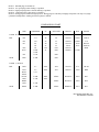
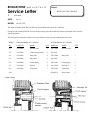
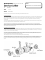
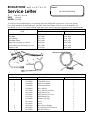
DRY CHARGED STORAGE BATTERIES . . . . . . . . . . . . . . . . . . . . . . . . . . . . . . . . . . . . . . . . . . . 3
SERVICE LETTER INDEX SYSTEM . . . . . . . . . . . . . . . . . . . . . . . . . . . . . . . . . . . . . . . . . . . . . . . 5
SPARK PLUG RECOMMENDATIONS . . . . . . . . . . . . . . . . . . . . . . . . . . . . . . . . . . . . . . . . . . . . . 6
ENGINE OVERHEATING . . . . . . . . . . . . . . . . . . . . . . . . . . . . . . . . . . . . . . . . . . . . . . . . . . . . . . . . 8
SPARK ARRESTER . . . . . . . . . . . . . . . . . . . . . . . . . . . . . . . . . . . . . . . . . . . . . . . . . . . . . . . . . . . . 10
SET-UP PROCEDURE & PRE-DELIVERY SERVICE – 175 DUAL TWIN . . . . . . . . . . . . . . . 11
BATTERY CHARGING – 50-60 SPORT . . . . . . . . . . . . . . . . . . . . . . . . . . . . . . . . . . . . . . . . . . . . 13
175 OIL INJECTION PUMP MODIFICATION . . . . . . . . . . . . . . . . . . . . . . . . . . . . . . . . . . . . . . 14
MAIN JET SIZES . . . . . . . . . . . . . . . . . . . . . . . . . . . . . . . . . . . . . . . . . . . . . . . . . . . . . . . . . . . . . . . 15
PISTONS AND RINGS . . . . . . . . . . . . . . . . . . . . . . . . . . . . . . . . . . . . . . . . . . . . . . . . . . . . . . . . . . 16
BS 90 OIL INJECTION PUMP . . . . . . . . . . . . . . . . . . . . . . . . . . . . . . . . . . . . . . . . . . . . . . . . . . . . 17
BS 175 HIGH SPEED OPERATION IN HOT WEATHER . . . . . . . . . . . . . . . . . . . . . . . . . . . . . 18
OIL INJECTION SYSTEM . . . . . . . . . . . . . . . . . . . . . . . . . . . . . . . . . . . . . . . . . . . . . . . . . . . . . . . 20
175 CHARGING SYSTEM . . . . . . . . . . . . . . . . . . . . . . . . . . . . . . . . . . . . . . . . . . . . . . . . . . . . . . . 21
LEFT AND RIGHT UP SWEPT MUFFLER PARTS . . . . . . . . . . . . . . . . . . . . . . . . . . . . . . . . . . 23
BS/175 POINTS AND CONDENSER . . . . . . . . . . . . . . . . . . . . . . . . . . . . . . . . . . . . . . . . . . . . . . 24
B/S 50 SPORT FRONT FORK . . . . . . . . . . . . . . . . . . . . . . . . . . . . . . . . . . . . . . . . . . . . . . . . . . . . 26
B/S 175 GEAR TIMING . . . . . . . . . . . . . . . . . . . . . . . . . . . . . . . . . . . . . . . . . . . . . . . . . . . . . . . . . 28
B/S CRANKSHAFT REPAIRS . . . . . . . . . . . . . . . . . . . . . . . . . . . . . . . . . . . . . . . . . . . . . . . . . . . . 29
175SR AIR CLEANER INSTALLATION . . . . . . . . . . . . . . . . . . . . . . . . . . . . . . . . . . . . . . . . . . . 31
BS350GTR OIL PUMP TIMING . . . . . . . . . . . . . . . . . . . . . . . . . . . . . . . . . . . . . . . . . . . . . . . . . . . 32
BS350 CLUTCH CHANGE . . . . . . . . . . . . . . . . . . . . . . . . . . . . . . . . . . . . . . . . . . . . . . . . . . . . . . . 33
BS350GTR CLUTCH . . . . . . . . . . . . . . . . . . . . . . . . . . . . . . . . . . . . . . . . . . . . . . . . . . . . . . . . . . . . 34
BS350GTR PERFORMANCE AND TUNING . . . . . . . . . . . . . . . . . . . . . . . . . . . . . . . . . . . . . . . 36
BS175 OIL PUMP REPAIR KIT . . . . . . . . . . . . . . . . . . . . . . . . . . . . . . . . . . . . . . . . . . . . . . . . . . . 37
REPAIR STUDS . . . . . . . . . . . . . . . . . . . . . . . . . . . . . . . . . . . . . . . . . . . . . . . . . . . . . . . . . . . . . . . . 38
SUGGESTIONS FOR FINE TUNING THE BRIDGESTONE 350 GTR . . . . . . . . . . . . . . . . . . . 39
MODIFICATION OF 2ND GEAR A AND 4TH GEAR B . . . . . . . . . . . . . . . . . . . . . . . . . . . . . . . . 41
100 TRAIL RECTIFIER . . . . . . . . . . . . . . . . . . . . . . . . . . . . . . . . . . . . . . . . . . . . . . . . . . . . . . . . . . 42
BRIDGESTONE 350 GTR ENGINE REPAIR . . . . . . . . . . . . . . . . . . . . . . . . . . . . . . . . . . . . . . . . 43
WIRING MODIFICATION FOR BRIDGESTONE 200 RS AND 200 SS . . . . . . . . . . . . . . . . . 44
STANDARD EQUIPMENT MIRRORS . . . . . . . . . . . . . . . . . . . . . . . . . . . . . . . . . . . . . . . . . . . . . 45
100 TMX HANDLEBAR . . . . . . . . . . . . . . . . . . . . . . . . . . . . . . . . . . . . . . . . . . . . . . . . . . . . . . . . . 46
SET-UP PROCEDURE AND PRE-DELIVERY SERVICE
CHIBI by Rockford . . . . . . . . . . . . . . . . . . . . . . . . . . . . . . . . . . . . . . . . . . . . . . . . . . . . . . . 48
SET-UP PROCEDURE AND PRE-DELIVERY SERVICE
C435 CHIBI DELUXE by Rockford . . . . . . . . . . . . . . . . . . . . . . . . . . . . . . . . . . . . . . . . . . 50
BRIDGESTONE
by Rockford
Service Letter
#
SUBJECT
DRY CHARGED STORAGE BATTERIES
BSG-0002
DATE
MODEL
7/31/64
All
The fully charged battery acts as a voltage stabilizer in the electrical system. Because the magneto delivers
considerably more current than the rated voltage of the system, a fully charged battery is essential as a buffer
between the current generating source and the various light bulbs on the cycle.
A discharged battery does not provide sufficient electrical resistance to perform this "buffer" function and
light bulbs will be burned out when they are switched on due to the excessive current reaching them from
the magneto or generator through the discharged battery.
For this reason, it is important that the dealer properly fill and charge the battery just prior to delivering the
machine.
PRE-DELIVERY BATTERY SERVICE PROCEDURE
1.
2.
3.
4.
Fill battery to proper level with 1.260 specific gravity electrolyte.
Allow battery to stand for 2-8 hours without charging.
Inspect liquid level and add more electrolyte, if necessary.
Measure specific gravity with a hydrometer. Table 1 indicates the approximate degree to which the
battery is charged (stated as the percent charged) and the approximate ampere / hours of charge which
will be necessary to bring the battery to a fully charged condition.
TABLE 1
SP. GR. MEASURED
PERCENT CHARGED
APPROXIMATE CHARGE REQUIRED
(IN AMPERE/HOURS)
1.260
100%
0*
1.220
75%
18 A/H
1.160
50%
30 A/H
1.105
25%
45 A/H
*While it is theoretically possible, rarely, if ever, will a dry charged battery be found to be fully charged
when the electrolyte is added.
5. To charge the filled battery, a 2-½ A/H charge rate may be used in the initial state of charging. The charge
is then completed with a ½ Amp, trickle charge. (See Note 1). The approximate charging time for each of
these two charge rates is indicated in Table 2. This table is based on the hydrometer reading taken in 4 above.
IMPORTANT
CHECK TEMPERATURE OF BATTERY CASE FREQUENTLY WHILE CHARGING. TEMPERATURE
MUST NEVER EXCEED 115 (WARM TO THE TOUCH) IF CASE BECOMES HOT, REDUCE
CHARGING RATE. OVERHEATING WILL CAUSE SEVERE BATTERY DAMAGE. (See Note 1).
TABLE 2
SP. GR.
@ 70E
APPROXIMATE
CHARGING TIME
@ 2.5 AMP/HOUR
APPROXIMATE
CHARGING TIME
@ ½ AMP/HOUR
1.240
2 Hour
plus
10 Hour
1.220
4 Hour
plus
20 Hour
1.160
8 Hour
plus
20 Hour
1.105
10 Hour
plus
30 Hour
AGAIN NOTE THAT IF BATTERY CASE BECOMES HOTTER THAN 115E (WARM TO THE TOUCH)
CHARGE RATE MUST BE REDUCED IMMEDIATELY!
NOTE 1
As a matter of practice, the maximum charge rate depends largely on the air temperature of the area where
the battery is being charged. A charge rate of up to 50% of the total charge required (see Table 1) can be
used IF TEMPERATURE OF THE BATTERY CASE DOES NOT RISE ABOVE THE POINT AT WHICH
IT IS JUST WARM TO THE TOUCH (115E F) . Therefore, the cooler the surrounding air temperature, the
higher the allowable charge rate.
As an example, assume the specific gravity of the electrolyte in the battery measures 1.220. Table 1 indicates
a charge of 18 A/H will be required. Assuming that the air temperature is cool enough to hold battery case
temperature below 115E F., a charge rate of 9 A/H can be used (50% of 18 A/H).
CHARGING CAUTIONS
1. DO NOT OVERCHARGE. Take specific gravity readings frequently during charging period.
2. CONNECT CHARGER CORRECTLY. Positive lead to positive terminal, negative lead to negative
terminal.
3. Set charger for correct voltage (6V or 12V).
4. DO NOT LET FILLED, UNCHARGED BATTERY STAND LONGER THAN 12 HOURS BEFORE
CHARGING.
ROCKFORD MOTORS, INC.
SERVICE DEPARTMENT
BRIDGESTONE
by
Rockford
Service Letter
#
SUBJECT
SERVICE LETTER INDEX SYSTEM
BSG-00??
DATE
MODEL
7/31/64
All
Effective immediately, a new indexing and numbering system has been added covering Rockford Service
Letters.
Where the Service Letter applies to one model only, the index number prefix will be the factory model
designation of the merchandise to which the letter applies.
(The factory model designation appears on the serial number plate of the vehicle).
Thus, the indexing system operates as follows:
1. Service letters numbered with the prefix "BSHM" - pertain to model BS-HM/S, Bridgestone "50"
(Rockford Model C204).
2. Service letters numbered with the prefix "BS7-" pertain to models BS-7S and BS-7D, Bridgestone 7
Standard and Bridgestone 7 Deluxe (Rockford Models C206 and C207).
3. Service letters numbered with the prefix "BS90-" pertain to models, BS-90 and BS-90T, Bridgestone
90 and Bridgestone 90 Trail-Scrambler (Rockford Models C208 and C209).
4. Service letters numbered with the prefix "BSG-" pertain to more than one model or cover a general
subject.
The Service Letters should be filed by prefix and number for ready reference.
All pertinent previously issued service letters will be re-issued to conform to the new system.
ROCKFORD MOTORS, INC.
SERVICE DEPARTMENT
BRIDGESTONE
by
Rockford
SUBJECT
Service Letter
#
SPARK PLUG RECOMMENDATIONS
BSG-0015 revised
DATE
MODEL
8/1/6?
All
Listed below are the NGK and Champion spark plugs recommended for use in Bridgestone motorcycles, depending
upon the type of service in which the cycles are used.
Note particularly that the plugs listed in the last column are suitable only in those instances where the cycle is used
for extended periods of time at close to its maximum speed, such as in road racing or extended touring.
MODEL
BS-HMS
BS-7S & D
BS-50 SP
BS-60 SP
BS-90 STD
BS-90 T
BS-90 M
BS-90 SP
BS-90 R
BS-100 SP
BS-100 R
BS-100 T
BS-100 GP
BS-100 TMX
BS-175 DT
& HS
BS-175R
BS-200 RS
& SS
BS-350 GTR
PLUG BRAND
NGK
CHAMPION
NGK
CHAMPION
NGK
CHAMPION
NGK
CHAMPION
NGK
CHAMPION
NGK
CHAMPION
NGK
CHAMPION
NGK
CHAMPION
NGK
CHAMPION
NGK
CHAMPION
NGK
CHAMPION
NGK
CHAMPION
NGK
CHAMPION
NGK
CHAMPION
NGK
CHAMPION
NGK
CHAMPION
NGK
CHAMPION
NGK
CHAMPION
STANDARD
NOTE 1
B-6
I-8
B-6
I-8
B-7
I-4
B-8
I-4
B-7H
L-5
B-7H
L-5
B-7HZ
L-5
B-7H
L-5
B-8HN
L-57R
B-8H
L-57R
B-8HN
L-57R
B-8H
L-57R
B-8H
L-57R
B-8H
L-57R
B-8H
L-57R
B-8HN
L-57R
B-8H
L-57R
B-8H
L-57R
LOW SPEED
NOTE 2
B-4
I-12
B-4
I-12
B-6
I-8
B-7
I-8
B-6H
L-7
B-6H
L-7
B-6H
L-7
B-6H
L-7
B-8H
L-57R
B-7H
L-5
B-8H
L-57R
B-7H
L-5
B-7H
L-5
B-7H
L-5
B-7H
L-5
B-8H
L-57R
B-7H
L-5
B-7H
L-5
HIGH SPEED
NOTE 3
B-7
I-4
B-7
I-4
B-8
I-62R
B-8
I-62H
B-7HC
L-60R
B-7HC
L-60R
B-7HC
L-60R
B-7HC
L-60R
B-9H
L-54R
B-9H
L-54R
B-9H
L-54R
B-9H
L-54R
B-9H
L-54R
B-9H
L-54R
B-9H
L-54R
B-9H
L-54R
B-9H
L-54R
B-9H
L-54R
COMPETITION
NOTE 4
B-7C
I-60R
B-7C
I-60R
B-8C
I-60R
B-8C
I-60R
B-8H
L-57R
B-8H
L-57R
B-8H
L-57R
B-8H
L-57R
B-9HN
–
B-8HN
L-57R
B-9HN
–
B-8HN
L-57R
B-8HN
L-57R
B-8HN
L-57R
B-8HN
L-57R
B-9HN
–
B-8HN
L-57R
B-8HN
L-57R
RACING
NOTE 5
B-8
I-62R
B-8
I-62R
B-8N
I-57R
B-8N
I-57R
B-9H
L-54R
B-9H
L-54R
B-9H
L-54R
B-9H
L-54R
–
–
B-9HN
L-54R
–
–
B-9HN
L-54R
B-9HN
L-54R
B-9HN
L-54R
B-9HN
L-54R
–
–
B-9HN
L-54R
B-9HN
L-54R
NOTE 1: Standard plugs for normal use.
NOTE 2: Low speed plugs where fouling is a problem.
NOTE 3: High speed plugs where electrode burning is a problem.
NOTE 4: Competition plugs (short track or scrambles.)
NOTE 5: Racing plugs for continuous high speed use. Racing plugs are extremely cold plugs and operate well only at very high
cylinder head temperatures. Starting and warm up may be difficult.
COMPARISON CHART
NGK
CHAMPION
AC
AUTO LITE
BOSCH
KLG
LODGE
B-4
J-11
46
A9
W123T3
TFS30
CAN 14
B-6
B-7
45
44
43
C42
41
A7
A5
A3
A703
A603
W145T3
W175T3
W190
W225T3
W240T1
TFS50
FS70
FS75
C14
HAN14
2HAN14
HHN
B-8
J-8J
J6J
J4J
J2J
J-60R
J-59R
J-57R
B8N
T-54R
14 M/M d REACH
HOT
B7C
B77C
COLD
FS100
A403
A203
14 M/M ½ REACH
HOT
COLD
B6H
L-7
47FF
AE4
W175T1
F75
HF-2H
B7H
B7HC
B7HZ
B77HC
B8H
B8HN
B9H
L-5
L-5J
45FF
AE2
W225T1
F100
HNP
L-60R
L-57R
44FF
42FF
AE603
W310T16
F250
R47
AE403
W370T16
F280
R49
AE203
W400T16
F310
R51
BIOH
L-57R
L-54R
ROCKFORD MOTORS, INC.
ROCKFORD, ILLINOIS
BRIDGESTONE
by
Rockford
SUBJECT
Service Letter
#
ENGINE OVERHEATING
BSG-0018
DATE
6/15/65
MODEL
All
The major causes of engine overheating are the following:
1. Improper break-in procedure.
2. Improper fuel oil mixture.
3. Incorrect ignition timing (see Service Letter BSG-0019)
4. Incorrect spark plug in use (see Service Letter BSG-0015)
5. Spark plug incorrectly gapped
6. Faulty points & condenser
7. Dirt in carburetor
8. Carbon accumulation in cylinder ports
9. Excessively heavy oil in transmission case.
10. Tires underinflated; brake drag; chain too tight
1. Improper Break-In. One of the most frequent causes of engine damage due to overheating is improper
break-in. There appears to be some confusion in the field about the necessity of break-in because some
2-cycle engines such as chain saws and outboards do not require it. IT IS IMPORTANT TO NOTE
THAT ALL MOTORCYCLES, REGARDLESS OF BRAND, REQUIRE ENGINE BREAK-IN.
Chain saws are not run continuously at high R.P.M nor are they required to accelerate under load, thus
avoiding overheating. Outboards are water cooled and excessive heat is easily controlled.
All motorcycle manufacturers specify break-in periods ranging from 250 to 2500 miles, depending upon
the type of engine used. Friction is greater during break-in until rings have had an opportunity to seat and
the cylinder wall has acquired a glaze. Bridgestone cycles should be run-in for a minimum of 250 miles.
Sustained high speeds should be avoided for at least 500 miles, preferably 1000 miles, YOU MUST
IMPRESS THESE FACTS UPON PURCHASERS:
1.
2.
3.
4.
5.
Observe maximum break-in speeds
Avoid fast engine warm up.
Avoid fast starts
Avoid fast shifting through the gears
Avoid overloading
Once a Bridgestone cycle is broken in properly, it is the most trouble-free machine available as attested
to by the number of large rental operators who are discontinuing other makes in favor of Bridgestone.
2. Fuel & Oil Mixture. It is important to use the proper oils and correct mixing ratios. Always use a good
grade of regular gas mixed with a brand name 2-cycle oil that is recommended for air cooled engines.
Never use special additive oils, or high ratio oils (50:1 or 100:1) Always use 15:1 ratio for break-in and
20:1 thereafter.
3. Incorrect ignition timing. The next most frequent cause of overheating is excessively advanced ignition
timing. Service Letter BSG-0019 covers the timing procedure and should be carefully noted by all service
personnel because of its importance.
4. Incorrect Spark Plug in Use. (See Service Letter BSG-0015.) A spark plug not recommended for use
under the particular operating conditions can result in overheating. Select the correct plug based on the
information given in Service Letter BSG-0015.
5. Spark Plug Incorrectly Gapped. An incorrectly gapped plug can effect Ignition timing. The problem is
most frequently found when an American- made plug is installed. The standard equipment NGK plugs
are factory gapped within the correct .025 – .028 range. American plugs will almost always be factory set
at a wider gap. Gap should be set before installation.
6. Faulty Points and Condenser. Check point surfaces for wear. Check condensers against specifications as
set forth in Service Letter BSG-0008.
7. Dirt In Carburetor. This condition, obstructs fuel flow and results in running too lean a mixture which
causes overheating.
8. Carbon Accumulation in Cylinder Ports. A carbon accumulation in transfer and exhaust ports can
restrict the flow of fuel mixture and exhaust gasses. This will result in the generation of excessive heat.
9. Transmission Oil Too Heavy. Excessively heavy oil in the transmission case causes the engine to
overwork due to extra drag. The transmission should be filled with the correct amount of S.A.E. 10W-30
motor oil.
10. Tires, Brakes, Chain. These items must be periodically checked to avoid placing an abnormal load on the
engine due to drag.
SERVICE DEPARTMENT
BRIDGESTONE
by
Rockford
SUBJECT
Service Letter
#
SPARK ARRESTER
BSG-0021
DATE
MODEL
7/1/65
All
The mufflers supplied on Bridgestone cycles are not designed or approved to be used as spark arresters.
In areas where spark arresters are required by the U.S. Forestry Service, we suggest the use of an Erickson
Products Co. "Gill type" spark arrester. Part No. 3CIP.
These spark arresters are available from:
Erickson Products Co.
1960 Carroll Avenue
San Francisco, California
They are also available from some dealers in heavy "use" areas.
This spark arrester can be easily attached to the end of the muffler for approved use by the U.S.F.S.
ROCKFORD, ILLINOIS
BRIDGESTONE
by
Rockford
Service Letter
#
SUBJECT
SET-UP PROCEDURE & PREDELIVERY SERVICE – 175 DUAL TWIN
BSG-0024
DATE
9/5/65
MODEL
All
I.
SET UP
The attached sheet details the set-up procedure for the BRIDGESTONE 175 DUAL-TWIN.
II. PRE-DELIVERY SERVICE
A. OIL INJECTION. The Oil Injection system is factory adjusted for proper operation. Fill the oil supply tank with 2-cycle
oil. Be certain to instruct the purchaser to regularly check the oil supply through the glass inspection port. IT MUST
NEVER BE ALLOWED TO RUN DRY!
B. FUEL. Fill the fuel tank with a 20:1 mixture of regular gas and 2 cycle oil (1 quart of oil in 5 gallons of gasoline). This
mixture is to be used during the 1st 250 miles of operation only. Thereafter, instruct the customer to fill the tank with
"regular" gasoline only.
C. BATTERY – Fill and charge the battery following the procedure in Service Letter BSG-0002.
D. TRANSMISSION – Fill the transmission case with 25 ounces of SAE motor oil. Transmission oil level is checked by
removing the oil level plug located just in front of the kick starter shaft. Do not overfill the transmission case.
E. OIL PUMP GEAR BOX – The Oil Injection pump is gear driven by the crankshaft and gear cavity oil level must be
checked before operation.
The gear cavity is located behind the oil pump and left carburetor (Figure 1 ). This cavity must be kept filled with a good grade of 30
weight motor oil. To fill, proceed as follows:
A. Remove left carburetor cover.
B. Remove oil level screw (indicated by arrow in figure 1.) This oil level screw is easily identified because it has a red fiber gasket
under it. (Note: The carburetor has been removed in figure 1 for clarity.)
C. Lean the cycle to the right and fill the gear cavity through the oil level hole, using a pressure-type oil can. Note: Because of air
trapped in the gear cavity, it may be difficult to determine the exact level. For an accurate measurement of the oil level, put cycle
upright and kick the starter several times. Oil will level itself and trapped air will be forced out. Oil level should reach lower edge of
oil level plug screw hole. Oil level should be checked every 500 miles.
Figure 1
F. ADJUSTMENTS
A. Tire Pressure – 24 to 26 lb. – Front
26 to 30 lb. – Rear
B. Brakes – check and adjust as described in owner's manual.
C. Horn – check for proper operation.
D. Lights – check all lights for proper operation.
E. Axle Nuts – be certain both front and rear axles are properly secured. Cotter pin must be installed in castle nut on
front axle.
F. Chain – check and adjust as required. (See owner's manual)
G. Steering Damper – check for proper operation. The damper is intended for use at high speed only. Do not
over-tighten.
H. Idle – adjust idle, if necessary, by visually checking the position of the carburetor throttle valves. (See owners manual)
Adjust cable adjusters on top of carburetors so that, with throttle grip closed, 1/32" of free play can be felt in the
throttle cable at each carburetor.
I. Oil Injection Adjustment – the entire oil injection system is designed to provide the correct oil mixture at all speeds.
The only adjustment it will ever need is the cable adjustment.
The oil pump volume is affected by the position of the throttle and varies from 20 to 1 mixture at full throttle to 100
to 1 at idle.
To adjust the oil pump control cable proceed as follows:
a. Remove left carburetor cover.
b. Turn throttle grip to maximum open position.
c. Check the oil pump control arm (where the cable is connected) and note the pin in the oil pump body and 2 stops on the
control arm. (Fig. 2). At the maximum open throttle position the stop should be within l/8 inch or the stop pin. If the stop
clearance is open more than 1/8 inch or the stop is closed against the pin, adjustment is necessary.
d. Cable adjustment is made at the cable adjusting screw located above the left carburetor housing, directly in front of the
generator. Loosen cable adjusting screw lock nut and turn adjusting screw in for additional stop clearance and out for less
until 1/8 inch of stop clearance is observed with the throttle at maximum open position.
NOTE:
A. Do not adjust to less than l/8 inch clearance.
B. When throttle is closed after adjustment, the
oil pump control arm may not return to its
closed position and may appear to be faulty.
However, the oil pressure in the pump sometimes
holds the control arm open when it is operated
without the engine running. This can be checked by
running the engine or operating the kick starter.
III. BREAK-IN
FIRST 250 MILES – Fill oil injection supply tank with 2
cycle oil and fill fuel tank with a 20:1
gas-oil mixture. Do Not Exceed 40
MPH for first 250 miles. Do not run
Figure 2
at any one speed for long periods. Vary the speed constantly.
250 TO 500 MILES –
Fill fuel tank with regular gas only. Be certain oil injection supply tank is full. Do Not
Exceed 50 MPH. Vary speed constantly during this period.
500 TO 750 MILES –
Do Not Run Continuous Maximum Speed.
CHECK OIL INJECTION TANK LEVEL DAILY. Engine will be severely damaged if tank is allowed to run dry.
NOTES:
1. A 20:1 gas/oil mixture is used in addition to oil injection during first 250 miles to insure proper break-in of engine and oil
pump.
2. Never run engine at a constant speed during break-in. Run it up to the maximum allowable speed for a minute or two and then
back down to a lower speed. Repeat this procedure constantly.
3. Clean spark plugs every 100 miles during break-in.
4. Change transmission oil after first 250 miles and after 750 miles. Then change at regular recommended intervals.
5. Check and recharge battery if necessary after first 250 & 500 miles. At slow speeds battery does not charge at normal use rates.
6. Check frequently for normal chain stretch and adjust as required.
BRIDGESTONE
by
Rockford
Service Letter
#
SUBJECT
BATTERY CHARGING – 50-60 SPORT
BSG-0024
DATE Jan. 1,1966
MODEL
50-60 SPORT
Listed below are two methods of increasing the charge rate on the B/S 50-60 Sport.
1. Connect both the yellow wire and the white wire from the key switch to the yellow wire from the
charging coil in the magneto. The white wire from the magneto is left disconnected.
This wiring change will slightly increase the charging rate.
2. For chronic problems caused from the cycle being driven only at very low speeds, the charging coil
from the B/S 7 Standard can be installed (part no. E19221) to increase charging. This coil must be
connected as shown in the 50-60 Sport wiring diagram.
NOTE:
When either method is used, battery water should be checked frequently and water added as necessary.
ROCKFORD MOTORS, INC.
ROCKFORD, ILLINOIS
BRIDGESTONE
by
Rockford
Service Letter
#
SUBJECT
175 OIL INJECTION PUMP
MODIFICATION
BSG-0029 revised
DATE Jan. 1,1966
MODEL B/S 175
Bridgestone 175 Dual Twins manufactured after Serial No. 16V, are equipped with a modified oil injection pump,
The new pump is equipped with ball and spring check valves in each of the pump body oil outlets.
The springs fit Inside the union bolts which are unchanged from previous models.
POINTS TO REMEMBER WHEN DISMANTLING OIL PUMP:
1. Ball check, valves are installed only in the outlet ports. (Never in the inlet port.)
2. Ball check valves cannot be installed in the old style pumps that were not
originally equipped with them.
3. When assembling the unit, first install the ball in the outlet port hole. Next, install
the spring into the union bolt. Then with the oil line connector and packing
washers installed on the bolt, screw the bolt into the outlet port hole .
4. The style of oil pump can be determined by viewing into the outlet port holes. The outlets on the old style pumps
have no ball valve seats machined in them and the check ball will pass through the outlet, into the oil pump
body.
The new style pumps have check ball valve seats machined in the outlet ports.
5. New style oil pump assemblies are interchangeable with the old style assembly.
An additional change was made in Serial No. 16B. This change incorporates the ball and spring check valves into a
new style outlet connector. Part Number 1502-8000 check valve connector.
The ball and spring are assembled inside of the new connector and eliminate
the possibility of incorrect assembly or loss of these parts. The new connectors
are easily identified because they are made of brass instead of aluminum.
These new connectors are Interchangeable on any of the old type pumps.
When they are installed on old type pumps, the ball and spring must be
eliminated from the connecting bolts.
Any old type pump can be converted to the latest style by installing 2 of these
new outlet connectors. The old type union connector P/N 1565-8000 has been
abolished.
ROCKFORD MOTORS , INC .
ROCKFORD, ILLINOIS
BRIDGESTONE
by
Rockford
Service Letter
#
SUBJECT
MAIN JET SIZES
BSG-0033 revised
DATE
MODEL
2-1-68
ALL
Listed below are the carburetor main jet sizes that are used as standard equipment on Bridgestone cycles. Also listed
are other sizes that are available.
PART NO.
SIZE
FOR 9MM CARBURETOR
1635-3000
- 70
1635-3000
- 80
FOR 15 MM CARBURETOR
1635-5000
- 95
- 100
- 110
- 120
- 130
- 140
- 150
STANDARD
BS-HMS
BS-7
C204
C206-207
BS-90 Before 12N
BS-50-60 Sport C300-301
BS-90T
BS-90 After 12N
C209
C208-210
FOR 17MM CARBURETOR AND OVER
1635-5010
- 75
- 80
- 85
- 90
- 95
BS-90 Sp Before 14L
- 100
BS-90 Sp After 14L & BS 175DT & HS
- 110
BS-100 Sp - 100T
C314-C319
- 120
- 130
BS-350 GTR/GTO
- 140
BS-350 GTR
C320
- 150
- 160
- 170
- 180
- 190
- 200
- 210
- 220
- 230
- 240
- 250
- 260
- 270
- 280
- 290
- 300
BRIDGESTONE
by
Rockford
SUBJECT
Service Letter
#
PISTONS AND RINGS
BSG-0036
DATE
3-1-68
MODEL
BS90 & 175
Listed below are the piston and ring sets used on the Bridgestone 90 and 175 DT.
MODEL
PISTON PART NO.
RING SET PART NO.
BS-90STD -90T - 90M
1341-5000
1305-5000
BS-90 SPORT
1341-5010
1305-5010
BS-175 DT
1341-5010
1305-5010
NOTE :
1. Pistons for the 90 STD - 90T - 90M could be used for replacement in the 90 Sport or 175 but only in cases of
emergency (they are of a harder material and will wear the chrome faster.)
2. Pistons for the BS 90 Sport and BS 175 are not interchangeable and cannot be used in the cast iron cylinders of
the BS 90 STD - 90T - 90M. (They are of a softer material and will wear rapidly against cast iron.)
3. The chrome plated ring used in the BS 90STD - 90T - 90M cannot be used for the BS 90 Sport or 175. Chrome
will not operate properly against chrome.
4. Pistons made only for cast iron cylinders can be recognized by the small center drilled hole in the top of the
piston.
5. Pistons made only for chrome plated aluminum cylinders can be recognized by the small flat spot on the top of
the piston.
6. On models produced before Jan. 1, 1967, the 90 Sport and 175 pistons can be distinguished by the "T" stamped
on the top of 175 pistons and no mark on 90 Sport pistons. On models produced after Jan. 1, 1967, pistons are
the same. (No mark)
7. For maximum service it is suggested that the correct part number and parts always be used for replacement.
8. When installing new pistons or cylinders, the piston clearance should be checked and adjusted for proper
operation. Check the piston clearance at the skirt of the piston and just above the ports in the cylinder.
Correct piston clearance for cast iron cylinders
.0025 - .004"
Correct piston clearance for aluminum cylinders
.0015 - .0025"
NOTE: On cast iron cylinders, the cylinder can be honed to adjust clearance, on aluminum cylinders, the piston must
be polished to adjust clearance.
ROCKFORD MOTORS, INC.
ROCKFORD, ILLINOIS
BRIDGESTONE
by
Rockford
Service Letter
#
DATE
MODEL
SUBJECT
BS 90 OIL INJECTION PUMP
BSG-0038
4-15-66
ALL BS90 With Oil Injection
Shown below is the BS 90 with oil injection pump and various parts that are assembled to it. If for any reason some
parts are removed or disassembled, it is important that the reassembly be exactly as shown, or serious engine damage
could result.
NOTE:
1. When assembling the intake port fitting, the spring must be installed first into the pump and then the check: ball.
Only a brass connector bolt can be used in this port.
2. When assembling the outlet port fitting the check ball is installed first into the pump and then the spring. Only a
brass connector bolt can be used in this port.
3. When assembling the oil line onto the rotary valve cover, the steel connector bolt must be used.
4. Care must be used not to overtighten any of the connect bolts.
5. If the oil pump assembly is removed from the engine it will be necessary to fill the oil pump gear box with oil
before operating.
BRIDGESTONE
by
Rockford
Service Letter
#
SUBJECT
BS 175 HIGH SPEED OPERATION IN
HOT WEATHER
BSG-0039
DATE
4-15-66
MODEL
BS-175
Whenever an engine is operated at any constant speed (particularly at or near maximum speed) for continuous
periods of time the engine's operating temperature slowly rises.
This rising temperature eventually will stabilize at a constant temperature.
Because of the varying termperature of the outside air, the combustion point of fuels and oils, and the condition of
the engine, in extreme cases where the outside air temperature is 60 degrees or more and the throttle is held open for
exceptionally long periods, the engine temperature could rise to a point where some loss of performance may result.
Listed below are suggestions and adjustments that should be made for hot weather and continuous high speed
driving.
1. SPARK PLUG
The spark plug furnished is standard equipment NGK B8H.
For break-in it is recommended that the NGK B7H or B77 HC spark plug be used to help prevent oil fouling.
CAUTION: Never operate the cycle at more than 40 MPH with this hotter plug.
For most ordinary driving where continuous high speeds are not encountered use the NGK B8H spark plug.
For continuous driving at or near maximum speed where outside air temperature is 60 degrees or more use a
colder spark plug such as NGK B9H or B10H.
2. FUEL
Always use a good grade of regular gas. Never use an ethyl or highly leaded gas.
3. OIL
Always use a good 2 cycle oil that is recommended for air cooled engines such as Rockford oil.
Never use oils of higher viscosity then SAE 40,high ratio mix oil, or special additive oils.
4. IGNITION TIMING
The ignition timing should never be adjusted to any setting other than the specified setting according to the
timing marks on the crankshaft. (See Service Letter BSG-0025)
5. OIL PUMP ADJUSTMENT
The oil pump cable adjustment should always be maintained according to the in- structions in the Service Letter
BSG-0024.
The adjustment should be checked after break-in and adjustment made if any cable stretch as changed the
setting. If the control arm has more than 1/8 inch clearance between the stop pin at full throttle, the engine may
not be receiving the proper amount of oil.
By properly servicing and adjusting the cycle, a much lower engine temperature can be sustained even in hot
weather.
This cooler running temperature will help extend spark plug life, increase performance, and lower the fuel
consumption insuring the customer of maximum service from his Bridge- stone motorcycle.
ROCKFORD MOTORS , INC .
ROCKFORD, ILLINOIS
BRIDGESTONE
by
Rockford
Service Letter
#
DATE
MODEL
SUBJECT
OIL INJECTION SYSTEM
BSG-0041
6-1-66
BS-175 DT
Dealer reports have indicated that a simple check of the oil injection system can prevent serious damage when the
machine is operated. Isolated reports Indicate that in some instances, the oil from the oil tank cannot reach the oil
pump because of dirty or plugged oil lines, tanks, or filter.
Whenever a new cycle is serviced the oil supply line to the pump should be removed at the pump and checked for
oil flow.
If a good supply of oil is not available at this line, check the tank, filter and lines and correct as necessary.
Oil must flow freely from this line to supply the engine with the proper lubrication.
ROCKFORD MOTORS, INC.
ROCKFORD, ILLINOIS
BRIDGESTONE
by
Rockford
SUBJECT
Service Letter
#
175 CHARGING SYSTEM
BSG-0042
DATE
6-1-66
MODEL BS-175DT
Listed below is the proper testing procedure to be used to check the generator and charging system on the B/S 175
DT. Testing must be performed in sequence as listed to locate the problem exactly and quickly.
Whenever testing and checking is to be performed, proceed as follows:
1. With the engine off, connect an amp meter into the circuit of the red wire on the battery at the fuse.
2. Start the engine in the daytime position of the key switch and observe the amp meter. At idle, the meter should
show a discharge of 2 amps. When the engine is run faster (4000 RPM) the meter should read "0". (No charge or
discharge) with models equipped with the high-low charge switch and the switch is in high charge position, the
"0" (no charge or discharge) will occur at 3000 RPM.
When the engine is run from 1/2 to full throttle, the amp meter should read 3 to 5 amps of charges. If all the
above tests are correct, the battery will stay charged when the cycle is operated for normal use.
3. If in the above test the 2 amp discharge was observed but no charging occured, suspect a faulty key switch and
proceed as follows:
4. Leave the red wire from the battery to the key switch disconnected and reconnect the amp meter, one lead to
positive of the battery and the other lead to the red post of the rectifier.
5. Restart the engine and test as in #2. If readings observed in this position are correct, the key switch is faulty and
replacement is indicated. If only discharge is observed, or (very low charge), 2 amp charge or less with high-low
charge switch on or 1 amp rectifier and proceed as follows:
6. Remove all wires from rectifier and connect a D.C. test light, (battery operated) one lead to the black post and
then touch the other lead to the yellow, blue, and white post one at a time. Now connect the test light in the same
manner but reversing the leads, to the black post and use the opposite lead to touch the same color terminals. In
the above test, the test light should have burned at all three connections in one test, and the test light should not
have burned in the other. (D.C . current will pass through a selenium rectifier in only one direction).
If the test light did not burn according to the above, the rectifier can be considered faulty.
If this test was normal, check the other half of the rectifier by using the red post and touching the yellow, blue,
and white and proceed as above.
If no positive conclusion can be made from this test, substitute another rectifier and test as in #2.
7. If the charge reading is still below the 3-5 amp with the high-low charge switch in the on position and operating
the high-low charge switch from on to off does not change the charge rate (at half to full throttle), suspect a
faulty switch and connect the brown wire from the generator to the white post of the rectifier, if charging is then
correct, replace the charge switch.
8. Generator Test. The generator can be checked with a test light. A battery operated test light should burn when
connected to any two of the yellow, blue or brown wires. The test light should not Light from any wire, (yellow,
blue or brown) when the other test lead wire is grounded to the generator frame.
9. If all components seem to test satisfactory and charging is still below standard, the generator magnets may be
weak and replacement would be necessary.
10. When checking the charging system always check the terminals on the wires ends to make sure they have good
contact.
11. For the proper readings, always use a charged battery when testing.
12. If the charge rate is found satisfactory and battery becomes discharged, the battery may be defective and will not
hold a charge. Check the battery after fully charging it and if the specific gravity of the fluid is not above 1.240,
the battery is probably defective. If the gravity is above 1.240 but will drop to below this reading in 24 hours
without connecting it in the cycle, the battery is defective.
13. If both the battery and the charge rate are satisfactory, suspect that the customer is running at too slow an
average speed and suggest that he operate the cycle in a lower gear to keep the engine turning faster (especially
for very slow speed city driving).
14. In some cases it has been found that a customer may ride with his foot on the brake pedal so that the stop light
burns continuously. It is recommended that the cycle not be allowed to idle more than the normal amount
necessary in operating the cycle. These practices help run the battery down and the customer should be
instructed against them.
BRIDGESTONE
by
Rockford
Service Letter
#
SUBJECT
LEFT AND RIGHT UP SWEPT MUFFLER
PARTS
BSG-0043
DATE
7-1-66
MODEL B/S 90M
B/S 60 Sport
Listed below are the parts used for left and right muffler assemblies for B/S 90 Mountain and B/S 60 Sport. Use this
list whenever ordering parts.
UP SWEPT MUFFLER FOR BS 90 MOUNTAIN
RIGHT SIDE MOUNTED
PART NAME
LEFT SIDE MOUNTED
EA1-63310
Muffler Assembly
6301-5040
EA1-63313
Inner Pipe
6320-5020
EA13-63331
Muffler Stay
6335-5020
EA13-63327
Front Protector
6332-3210
6333-5010 (EA13-63328)
Rear Protector
6333-5010
EA13-63329
Protector Bracket
(Not used)
EA13-63111
Exhaust Pipe
6351-5050
6362-5000 (EA1-63121)
Rubber Joint
6362-5000
UP SWEPT MUFFLER FOR BS 60 Sport
RIGHT SIDE MOUNTED
PART NAME
LEFT SIDE MOUNTED
EA13-63300
Muffler Assembly
6310-3220
EA1-63313
Inner Pipe
6320-5020
EA13-63331
Muffler Stay
6335-3210
EA13-63327
Front Protector
6332-3210
6333-5010 (EA13-63328)
Rear Protector
6333-5010
EA13-63329
Protector Bracket
(Not used)
GB21-63111
Exhaust Pipe
6351-3220
6362-5000 (EA1-63121)
Rubber Joint
6362-5000
ROCKFORD MOTORS, INC.
ROCKFORD, ILLINOIS
BRIDGESTONE
by
Rockford
SUBJECT
Service Letter
#
BS/175 POINTS AND CONDENSER
BSG-0046 REVISED
DATE
6-1-67
MODEL
BS/175
Various changes to the points, condenser and generator have been made since the beginning of production of the BS
175. Below are shown the 3 types of generators. Always check the type of generator involved to be sure the correct
parts are being used. The generator can be identified by matching the point type and location to one of the
illustrations below. Listed with each type of generator are the parts to be used for that generator.
Shown below is an illustration of the generator with the cap removed to expose the points and condenser. This type
of generator was used on all B/S 175 DT before Serial No. 16G-11760.
Replacement parts for the above generator are listed below:
PART NO.
DESCRIPTION
1703-8000
A.C. Dynamo
1736-8000
Breaker Cam (Double Lobe)
1752-8000
Left Contact Breaker Assembly
1753-8000
Condenser (Double Unit)
1757-8000
Right Contact Breaker Assembly
1741-8000
Timing Gear
NO REQ'D
1
1
1
1
1
1
RELATED PARTS
2101-8000
2114-8000
6811-8000-FAR
8603-8000
Crankcase Assembly
Upper Crankcase Plug
Left Side Cover
Charge Control Switch
All other parts are shown in the 175 Parts List.
1
1
1
1
Shown below is an illustration of the generator with the cap removed to expose the points and condenser. This type
of generator was used on all B/S 175 DT after Serial No. 16G-11761 up to Serial No. 16L-20757. This generator is
also used on all B/S 175 HS beginning production up to Serial No. 16L-20757.
Replacement parts for the above generator are listed below:
PART NO.
1703-8001
1736-8010
1752-8000
1756-8010
1758-8010
DESCRIPTION
A.C. Dynamo After 16G
Breaker Cam, Single Lobe
L & R Contact Breaker
Left Condenser
Right Condenser
NO REQ'D
1
1
2
1
1
1741-8010
1742-8010
09075-103
09002-101
09046-104
2101-8010
6811-8010-FAR
RELATED PARTS
Timing Gear
Idle Gear
Ball Bearing
12 Snap Ring
12 Wave Washer
Crankcase Assy
Left Cover Red
1
2
1
1
1
1
All other parts are common with previous production and are shown in 175 Parts List.
Shown below is an illustration of the generator with the cap removed to expose the points and condenser. This type
of generator is used on all B/S 175 DT and B/S 175 HS after Serial No. 16L-20758.
Replacement parts are listed below:
PART NO.
1703-8002
1736-8001
1739-8001
1751-8001
1752-8001
1753-8000
1757-8001
DESCRIPTION
A.C. Dynamo After 16L
Breaker Cam, Single Lobe
Breaker Cover
Breaker Base
Left Contact Breaker
Condenser (Double Unit)
Right Contact Breaker
NO REQ'D
1
1
1
1
1
1
1
All other parts are common with previous production and are shown in 175
Parts List.
ROCKFORD MOTORS, INC.
ROCKFORD, ILLINOIS
BRIDGESTONE
by
Rockford
SUBJECT
Service Letter
#
B/S 50 SPORT FRONT FORK
BSG-0048
DATE
9-1-66
MODEL
B/S 50 Sport
Listed below are the front fork assemblies and parts for B/S 50 Sport. When ordering parts, be sure to check serial
numbers and order accordingly. Example: All B/S 50 Sport serial numbers start with 13. This is the model code. The
3rd digit of the serial number is always an alphabetic letter. This letter indicates the month of manufacture. When
parts are described as before or after 13N it indicates that serial numbers before 13N, (13K, 13L, 13M) use the older
style part and serial numbers after 13N, (including 13N, 13O, 13P, 13Q, etc.) use the newer style part.
FRONT FORK FOR B/S 50 SPORT UP TO SERIAL NO. 13U022397
INDEX NO.
PART NO.
DESCRIPTION
NO REQ'D
14-0
14-1
GB1-41000-0-B
GB1-41100
GB1-41100-1
GB1-41120
GB1-41220
GB1-41171
GB1-41172
K6N3-8
GB1-41173
GB1-41173-1
GB1-41182
GB1-41183
HW-8
EA1-41251
SW-8
GB1-41310
GB1-41321
SW-8
GB1-41410-0-B
GB1-41420-0-B
GB1-41511
GB1-41521
EA1-41541
KHW-8
Front fork assy, black
Outer tube comp. before 13N
Outer tube comp. after 13N
Inner tube comp. L.
Inner tube comp. R.
Spring
Spring guide
8 mm small hex. nut
Outer tube nut before 13N
Outer tube nut after 13N
Bolt (upper bracket)
8 mm wave washer
8 mm flat washer
Axle bracket bolt
8 mm spring washer
Lower bracket complete
Lower bracket bolt
8 mm spring washer
Fork cover comp. L.
Fork cover comp. R.
Upper bracket
Handle holder
Bolt (handle holder)
8 mm small flat washer
1
2
14-2
14-3
14-4
14-5
14-6
14-7
14-8
14-9
14-10
14-11
14-12
14-13
14-14
14-15
14-16
14-17
14-18
14-19
14-20
14-21
1
1
2
2
2
2
2
2
2
2
1
1
1
2
2
1
1
1
2
4
4
RELATED PARTS
BEFORE 13U022397
AFTER 13U022398
PART NO.
DESCRIPTION
PART NO.
DESCRIPTION
GB11-42117
GB11-42118
GB1-71130-1
Fender Stay B
Fender Stay C
Front Brake Panel
4424-3211
4423-3211
7131-3202
Fender Stay B
Fender Stay C
Front Brake Panel
FRONT FORK FOR B/S 50 SPORT AFTER SERIAL NO. 13U022398
FIG NO.
PART NO.
DESCRIPTION
NO. REQ'D
1
2
3
4
5
6
7
8
9
10
10
11
12
13
14
15
16
17
18
19
20
20
21
22
23
0142-0845
0421-0816
4162-3201
4166-3201
4127-3200
4124-3201
0411-1022
4161-3201
4123-3200
4181-3201-CUR
4181-3201-CBK
4113-3201
4151-3201
0111-0832
09490-116
4114-3200
4116-3200
09566-109
4131-3201
4111-3202
4171-3201-CUR
4171-3201-CBK
4122-3201
4121-3201
0141-0822
4133-3201
4100-3201-CUR
4100-3201-CBK
Hex. bolt D (8x45 Hex. bolt)
Plane washer B
Handle holder
Lower handle holder
Dust Seal
Upper bridge bolt
Plane washer A
Upper bridge
Inner tube packing
Right fork cover, red
Right fork cover, black
Inner tube A. (Left)
Lower bridge
Hex. bolt A
26 Oil Seal
Outer tube nut
Cushion slide metal
32 O ring
Outer tube B. (Right)
Outer tube A. (Left)
Left fork cover, red
Left fork cover, black
Main spring guide
Front cushion main spring
Hex. bolt D (8x22 Hex. bolt)
Inner tube B. (Right)
Front fork assembly
Front fork assembly
4
4
2
2
2
2
2
1
2
1
1
1
1
2
2
2
2
2
1
1
1
1
2
2
1
1
1
1
BRIDGESTONE
by
Rockford
SUBJECT
Service Letter
#
B/S 175 GEAR TIMING
BSG-0051
DATE
11-1-66
MODEL
BS 175
On all Bridgestone 175 models produced after Serial No. 16G a new style generator is used. This new style generator
is driven from the engine and incorporates the use of a newly added idler gear.
The addition of this idler gear changes the procedure of the gear train timing.
To properly time the gears, proceed as follows:
1. The pinion gear must be aligned dot to dot on the crankshaft.
2. The clutch and pinion gear must be aligned dot to dot.
3. The idle gear has no timing marks and can be installed in any position.
4. The generator gear must be installed with the crankshaft, pinion gear, and clutch aligned, and the dot on the
generator pointing directly at the center of the idle gear. This will properly align the contact breaker cam and
crankshaft so that proper ignition timing will be possible. (See drawing)
NOTE:
The use of a single lobe cam for the points has changed the position of the points. The black wire to the points on
the bottom are for the right cylinder. The white wire to the points on top are for the left cylinder.
BRIDGESTONE
by
Rockford
Service Letter
#
DATE
MODEL
SUBJECT
B/S CRANKSHAFT REPAIRS
BSG-0057
3-1-68 REVISED
ALL
BRIDGESTONE CRANKSHAFT REPAIR PROGRAM
The repairs listed below include complete crankshaft disassembly, inspection of all parts and precision assembly and
alignment. For the repair of your crankshafts, simply send them prepaid to Rockford Motors, Inc. They must be
properly marked with your name and address and include specific instructions as to the repair requested.
STANDARD REPAIR CHARGES (Note A)
WITHOUT NEW
MAIN BEARINGS
FOR BRIDGESTONE 50-60 SPORT
Includes:
1 - Connecting Rod
1 - Crank Pin
1 - Crank Pin Bearing
FOR BRIDGESTONE 90-100 ALL MODELS
Includes:
1 - Connecting Rod
1 - Crank Pin
1 - Crank Pin Bearing
FOR BRIDGESTONE 175 ALL MODELS COMPLETE
Includes:
2 - Connecting Rods
2 - Crank Pins
2 - Crank Pin Bearings
1 - Center Oil Seal
1 - Center Roller Bearing
FOR BRIDGESTONE 175 ONE SIDE REPAIR
Includes:
1 - Connecting Rod
1 - Crank Pin
1 - Crank Pin Bearing
1 - Center Oil Seal
1 - Center Roller Bearing
FOR BRIDGESTONE 175 SPECIAL CENTER SEAL REPAIR
Includes:
1 - Center Oil Seal
1 - Center Roller Bearing
WITH NEW
MAIN BEARINGS
(NOTE B)
$8.50
$11.66
11.50
14.52
22.50
26.27
16.00
19.77
7.50
11.27
BSG-0057
3-1-68
REVISED
STANDARD REPAIR CHARGES (NOTE A)
WITHOUT NEW
MAIN BEARINGS
FOR BRIDGESTONE 350 COMPLETE
Includes:
2 - Connecting Rods
2 - Crank Pins
2 - Crank Pin Bearings
1 - Center Labyrinth
1 - Center O Ring
2 - Center Ball Bearings
2 - End Seals
FOR BRIDGESTONE 350 ONE SIDE
Includes:
1 - Connecting Rod
1 - Crank Pin
1 - Crank Pin Bearing
1 - Center Labyrinth
1 - Center O Ring
2 - Center Ball Bearings
2 - End Seals
FOR BRIDGESTONE 350 CENTER SEAL
Includes:
1 - Center Labyrinth
1 - Center O Ring
2 - Center Ball Bearings
2 - End Seals
NOTE A:
WITH NEW
MAIN BEARINGS
(NOTE B)
$31.50
$36.94
24.00
29.44
16.50
21.94
To compute Retail List Price, dealer is expected to add freight, installation, mark-up, etc.
To qualify for the standard repair charges, the returned crankshaft must have useable crankshaft halves.
NOTE B:
If the outside main bearings are still attached to your crankshaft, we will inspect them when they are
removed for our alignment procedure and proceed as follows:
1. If these bearings meet proper standards they will be reinstalled and you will not be charged for bearings.
2. If bearings are not sent in or if bearings do not meet proper standards.
(a) Bearings will be replaced and you will be billed for bearings only if you have authorized
replacement when you sent in the crankshaft.
(b) If you have not authorized replacement, we will assume you have bearings available and crankshaft
will be returned without main bearings.
ROCKFORD MOTORS, INC.
ROCKFORD, ILLINOIS
BRIDGESTONE
by
Rockford
Service Letter
#
SUBJECT
175SR AIR CLEANER INSTALLATION
BSG -0058
DATE
2-1-68 Revised
MODEL
175SR
Your Bridgestone 175 SR Racer is built for maximum performance so you can WIN races.
To provide maximum performance, air restriction to the carburetor is minimal. Relatively unrestricted air intake
provides more power, but has the obvious disadvantage of allowing some dust to pass through. There's usually no
problem except on dusty tracks.
Therefore, if you use your 175 Racer regularly for dirt track competition, you should install a filter type air cleaner.
A special kit, including all necessary parts, is available to simplify this modification. The special kit, stock number
SC 1471, has a special co-op cost price of $9 each.
Installation Instructions for 175 SR Air Cleaner
1. Remove right rear muffler mounting nut and loosen front muffler clamp so that muffler can be raised up from
its mounted position.
2. Remove generator strap nut and replace it with the short one supplied: (0222-0600)
3. Remove right carburetor cover.
4. Remove carburetor and disconnect the fuel line and throttle cable from it.
5. Set aside the old rubber cap and install the new type with the air inlet. Insert the throttle cable through t he hole
in the top of the cap and the fuel line through the hole in the side of the rubber cap.
6. Make sure that the cap mounting plate is in place and attach the throttle cable and fuel line to carburetor.
7. Reinstall carburetor and cap onto the engine.
8. Remove the clutch cable from the engine so that it can be pulled from behind the right muffler.
9. Insert the air cleaner assembly under the right muffler and position it over the mounting holes in the engine.
Fasten it securely with the 2 screws (0111-0514) and 2 washers (0411-0512)
10. Attach the rubber joint and metal air pipe in place between the air cleaner and the carburetor rubber cap.
11. Reattach the rear muffler mount and fasten the front and rear securely.
12. The clutch cable must be routed so that it passes in front of the right fuel valve, over the outside of the right
muffler and attach to the engine.
13. Replace the right carburetor cover and install the clamp spring onto the rubber carburetor cap.
14. Install the foam rubber gasket under the screen in the side cover.
15. Remove the left carburetor cover.
16. Disconnect the fuel line and throttle cable from the left carburetor.
17. Set aside the old rubber cap and install the new type with the air inlet. Insert the throttle cable through the hole in
the top of the cap and the fuel line through the hole in the side of the rubber cap.
18. Reconnect the throttle cable and fuel line to the carburetor.
19. Install the rubber joint and metal air pipe between the air cleaner and the carburetor cap. Secure the rubber
carburetor cap with the clamp spring.
20. Reinstall the left carburetor cover.
21. Install the foam rubber gasket under the screen in the side cover.
22. The use of the filter type air cleaner makes it necessary to change to leaner main jets for proper operation. It is
suggested that 1 size smaller main jet (220) be installed and tested. If in operation the machine is still too rich, it
will be necessary to change to 1 more size smaller main jet (210).
BRIDGESTONE
by
Rockford
Service Letter
#
DATE
MODEL
SUBJECT
BS350GTR OIL PUMP TIMING
BSG-0059
8-1-67
350
The oil pump on the BS 350 GTR can easily be removed from the engine and there is no timing necessary when
reinstalling it.
There is, however, a timing adjustment necessary if the pump is disassembled.
The distributor gear must be timed to the pump gear or no oil will be pumped. To time these gears, first install the
distributor gear into the pump housing and revolve it so that its timing mark is aligned with the hole for the pump
gear shaft. Then install the pump gear with the high edge of the cam aligned with the distributor gear. (See
drawings.)
After making sure that timing is correct, install the spring into the hole in the end of the pump gear shaft. Reinstall
pump housing cover and fasten with 3 screws and lock washers.
This pump does not have spring valves and the timing of the distributor gear opens and closes the various passages
as necessary so that It draws oil from the tank and forces it to each cylinder. There are spring check valves in the
connecting bolts at the outlet end of the oil lines. (Under the generator.) These valves prevent high engine vacuum
from pulling oil out of the lines.
ROCKFORD MOTORS, INC.
BRIDGESTONE
by
Rockford
SUBJECT
Service Letter
#
BS350 CLUTCH CHANGE
BSG-0060
DATE
8-15-67
MODEL
BS 350 GTR
The clutch assembly on the BS 350 GTR has been modified after Serial No. 21S01022.
Changes to the clutch include the revision of the pressure plate and clutch hub and the elimination of the set bolts
and spring guides.
The parts that are effected are listed below with sketches so that you may identify these new parts.
INDEX
BEFORE SERIAL NO. 21S01022
NO.
PART NO.
NAME
9-1
2211-9000
9-2
AFTER SERIAL NO. 21S01022
QTY
PART NO.
NAME
QTY
Pressure plate
1
2211-9001
Pressure plate
1
2213-9000
Clutch spring washer
6
Not used
9-4
2215-9000
Inner plate
6
2215-9000
9-5
2216-9000
Outer plate
1
Not used
9-6
2218-9000
Clutch spring
6
2218-9001
Clutch spring
6
9-7
2219-9000
Set bolt
6
0113-0616
Hex bolt A
6
9-8
2221-9000
Clutch hub
1
2221-9001
Clutch hub
1
9-26
–
–
09040-112
Plain washer
6
Inner plate
7
-
BRIDGESTONE
by
Rockford
Service Letter
#
SUBJECT
BS350GTR CLUTCH
BSG-0061
DATE
MODEL
10-20-67 Revised
BS 350
Bridgestone dealers have delivered over 1,500 Bridgestone 350 GTR's to customers who already have put many
thousands of miles on these cycles. Because this machine is new, we have called dealers regularly to learn what, if
any, improvements they might suggest. Most customers are completely satisfied, but we have had an occasional
report of objectionable clutch noise.
The factory is now adding (after serial number 21V04000) a new outer plate (2216-9001) and carburetor cover
grommet (2195-9010). This eliminates any objectionable clutch noise and has the unexpected advantages of making
the clutch even smoother to operate and unaffected by temperature. Most models manufactured before this factory
modification, when shipped from Rockford after October 15, will have been modified by making asimilar
modification, using new outer plate (2216-9010). You will be able to determine whether the unit has been modified
by the grommet at the bottom of the rear edge of the right carburetor cover. If the unit has not been modified,
modification kit SC1522 is available on special order from Rockford after October 15. The modification kit includes:
2216-9010
2195-9010
Outer Plate
Carburetor cover grommet
If your order states serial numbers of each cycle requiring modification, the kits will be sent at no charge.
Here's how to install the new outer plate (2216-9010):
1. Remove right carburetor cover (2176-9000)
2. Remove the 6 clutch set bolts (2219-9000)
3. Remove the pressure plate (2211-9000 or 2211-9001), clutch springs (2218-9000) or 2218-9001) and on models
before serial number 21S01022 spring holders (22l3-9000)
4. Remove all inner plates (2215-9000) and friction plates (2214-9000).
NOTE: On models before 21S01022, the thicker out plate (2216-9000) must also be removed.
5. Insert the new outer plate (2216-9010) with recessed or cut surface facing the clutch hub.
6. Reinstall a friction plate (2214-9000) and an inner plate (2215-9000).
NOTE: On models before 21S01022, the thick outer clutch plate (2216-9000) is not re-used.
7. Alternately re-install fiber friction plates (2214-9000) and metal inner plates (2215-9000) until 7 fiber and 6 metal
plates have been installed. On models before 21S01022, you will have the thick outer plate left over. On models
after 21S01022, you will have one inner plate left over.
8. Reassemble the pressure plate, springs, bolts, and spring holders, if any.
9. Make clutch adjustment as follows (see section 7 and 9, Parts Manual):
(1) Remove release screw cap (2179-9000)
(2) Loosen hex nut A (Reference 18 - Part #0211-0600)
(3) Screw in release adjusting screw (reference 14 - part #2267-5000) 1-1/2 turns
(4) Make clutch cable adjustment with clutch adjusting screws – see Page 28 of 350 GTR Service Manual.
10. Fit the carburetor cover grommet (2195-9010) to the air hole in the rear part of the carburetor cover (2176-9000)
and reinstall the carburetor cover.
PARTS LISTS AND SECTIONAL VIEWS OF THE 3 TYPES OF MODIFIED CLUTCHS ARE SHOWN BELOW.
FIELD MODIFICATION #l - USING SPECIAL OUTER PLATE (2216-9010)
(BEFORE SERIAL NO. 21S01022)
PART NO.
2211-9000
2213-9000
2214-9000
2215-9000
2216-9000
2218-9000
2219-9000
2221-9000
2216-9010
2195-9010
NAME
QTY
Pressure Plate
1
Spring Washer
6
Friction Plate
7
Inner Plate
6
Outer Plate
Not Used
Clutch Spring
6
Set Bolt
6
Clutch Hub
1
Special Outer Plate 1
Grommet
1
FIELD MODIFICATION #2 - USING
SPECIAL OUTER PLATE (2216-9010)
(AFTER SERIAL NO. 21S01022)
PART NO.
2211-9001
2214-9000
2215-9000
2218-9001
0113-0616
2221-9001
09040-112
2216-9010
2195-9010
NAME
QTY
Pressure Plate
1
Friction Plate
7
Inner Plate
6
Clutch Spring
6
Hex Bolt
6
Clutch Hub
1
Plain Washer
6
Special Outer Plate 1
Grommet
1
FACTORY MODIFICATION USING SPECIAL OUTER PLATE (2216-9001)
(AFTER SERIAL NO. 21V04022)
PART NO.
2211-9001
2214-9000
2215-9000
2218-9001
2218-9002
2221-9002
09040-112
2216-9001
2195-9010
NAME
QTY
Pressure Plate
1
Friction Plate
7
Inner Plate
6
Clutch Spring
6
Hex Bolt
6
Clutch Hub
1
Plain Washer
6
Special Outer Plate 1
Grommet
1
BRIDGESTONE
by
Rockford
Service Letter
#
SUBJECT
BS350GTR PERFORMANCE AND
TUNING
BSG-0062
DATE
10-1-67
MODEL
BS 350
After the break-in period, the factory oil pump setting on the Bridgestone 350 GTR may be too rich for normal
driving. Do not make any adjustment until after the break-in period, however. Then make only slight adjustments to
avoid over-correcting.
Before making any oil pump adjustment:
1. Make sure the carburetor throttle valves are properly synchronized (see page 41, Bridgestone 350 GTR Service
Manual).
2. Make sure the oil pump control cable is adjusted properly (see page 48, Bridgestone 350 GTR service manual).
3. Check the main jet. The 140 main jet is installed at the factory for break-in use. Performance after break-in may
be increased by switching to a 130 main jet (extra 130 main jets are packed with the service tools after Serial No.
16T01646). With the 130 main jet, the float setting should be 15/16", and the needle jet clip should be in the
second-from-the-bottom position.
4. Check the ignition timing according to the specifications on page 62 of the Bridgestone 350 GTR Service
Manual).
If, after these procedures have been accomplished, performance is below expectations (poor acceleration, unable to
attain high RPM, heavy smoking, spark plug fouling), adjust the small adjusting screw on the front of the oil pump.
It is held in place by a small hex lock nut.
Turn the adjusting screw only 1/8 of a turn (in for less oil, out for more). The cycle must then be run 10 to 20 miles
to see if oil volume is correct. The cycle should accelerate easily to 7500-8000 RPM in 1st, 2nd, 3rd, etc.
It may be necessary to make additional small adjustments if the cycle tends to reach a point and bog down (too rich,
loading, 4-cycling, etc.). Be sure to run the cycle 10 to 20 miles after each slight correction. Care should be used not
to cut the oil too much.
A properly adjusted Bridgestone 350 GTR should get between 250 and 300 miles per quart of 2-cycle oil.
ROCKFORD MOTORS, INC.
ROCKFORD, ILLINOIS
BRIDGESTONE
by
Rockford
SUBJECT
Service Letter
#
DATE
MODEL
BS175 OIL PUMP REPAIR KIT
BSG-0063
10-1-67
175
On an occasional Bridgestone 175, minor oil pump leaks can develop from normal wear of the oil seals. It is a
simple
problem to correct. As a special service, an Oil Pump Service Kit is available to restore a positive seal. The 5 parts in
the service kits are 4 oil seal replacements plus an improved cam cover now used in production.
For your convenience, the service kits are pre-packaged and can be ordered (List $1.20, Dealer Cost $.72) as
SC1521, or you can order the individual parts as listed below:
PART NO.
DESCRIPTION
LIST
QTY.
FOR
09066-126
26 "O" Ring
$ .28
1
Cam Cover
09066-127
13.5 "O" Ring
.11
1
Piston Cover
09066-128
5 "O" Ring
.11
1
Pump Shaft
09066-125
12 "O" Ring
.11
1
Worm Gear Cover
1595-8000
Cam Cover
.66
1
–
ROCKFORD MOTORS, INC.
ROCKFORD, ILLINOIS
BRIDGESTONE
by
Rockford
Service Letter
#
SUBJECT
REPAIR STUDS
BSG-0066
DATE:
MODEL:
9-20-70 REVISED
BS90 Sport, BS 175
To repair engines that have cylinder studs with stripped threads in the aluminum castings, the following stud repair
kits are available.
FOR BS 90 SPORT
To repair cylinder head studs that are stripped in the cylinder, order kit number SC 1450 @ $2.00.
This is a set of 4 repair studs with installation instructions and they are easily installed by tapping the holes in the
cylinder to standard 3/8" - 16 thread.
The regular cylinder head nuts and washers are used.
No modification to the cylinder head is necessary.
Tighten the head nuts to 125 inch pounds.
FOR BS 175DT, BS 175HS, MII RS, MII SS
To repair cylinder mounting studs that are stripped in the crankcase, order P/N SC 1489 @ $1.60 each including
instructions. These studs are easily installed by tapping the crankcase to standard 3/8" - 16 thread. No modification to
the cylinder head is necessary.
The regular cylinder head nuts and washers are used.
Tighten the head nuts to 150 inch pounds.
FOR BS 350 GTR and BS 350 GTO
To repair cylinder mounting studs that are stripped in the crankcase, order SC 1552 @ $1.80 each including
instructions.
Install the stud by tapping the crankcase to standard 7/16" - 20 thread. No modification to the cylinder or head is
necessary. Use the regular cylinder head nuts and washers.
Tighten the head nuts as follows:
MODEL
TORQUE TO
100 Sport, 100GP and 100 TMX
350 GTR and 350 GTO
125 inch pounds
175 inch pounds
ROCKFORD MOTORS, INC.
ROCKFORD, ILLINOIS
BRIDGESTONE
by
Rockford
Service Letter
#
BSG-0067
DATE
5-1-68
MODEL
BS350 GTR
SUBJECT
SUGGESTIONS FOR FINE TUNING THE
BRIDGESTONE 350 GTR FOR SMOOTHEST
OPERATION AND MAXIMUM
PERFORMANCE
The Bridgestone 350 GTR will operate quietly – even at idle – and deliver maximum performance – if it is properly
tuned. Here are the simple steps you can take to fine-tune your customers' 350 GTR engines. When you follow these
directions, you will synchronize the cylinders and eliminate vibration noise.
1. POINTS
Point gap adjustment must be between .012 - .016 inches. For best high speed performance it is desirable to have
both points set the same and as close to .012 as practical. Pitted or burned points should be replaced. Always clean
points of any oil and after checking.
2. SPARK PLUGS
Always use NGK B8H spark plugs for normal use. Keep plugs cleaned and gapped to .025 - .028 inches.
3. IGNITION TIMING
Ignition timing must be adjusted so that the points break exactly when the pin drops into the slot in the crankshaft.
When using a top dead center gage the points must break at .130 inches before top dead center. Ignition timing that is
set too fast (advanced) will surely cause rough running and may burn a hole in the piston.
4. CARBURETOR FLOAT ADJUSTMENT
The float setting must be adjusted to 15/16 inch while holding carburetor upside down and measuring from the
gasket seat (gasket removed) to the top of the float. Measuring is done without compressing the spring loaded float
valve. If the floats are not equal in height, twist the floats so they are equal in height and bend the float needle valve
tab to raise or lower the float level.
5. CARBURETOR CONTROL SYNC
Synchronize the carburetor valves by adjusting the cable adjusters so that the tops of both "O" marks on the valves
reach the top of the carburetor venturi at exactly the same time.
6. IDLE AIR SCREW SETTING
Turn both idle air screws in carefully until they just touch their seat and then screw them out 2 turns. Be careful not
to screw them in too tight. Too much pressure may damage the seat.
7. IDLE SPEED ADJUSTMENTS
The idle speed sync is the most important adjustment for smooth idling. The correct idle speed is 1800 rpm. Adjust
both carburetors so that each side's exhaust sound is the same. On an improperly adjusted engine, one cylinder may
be running smoothly and the other will be firing only occasionally. When the idle sync is properly adjusted, the
exhaust sounds will be the same and there should be a smooth flow of exhaust from both mufflers. To verify that the
engine is properly adjusted, turn each idle screw alternately in a slight amount and RPM should immediately drop
200-300 RPM and pick up when the screw is again turned out. If idle speed is then too fast, adjust both screws an
equal amount to obtain the proper RPM.
8. OIL CONTROL SYNC
Adjust the oil control cable so that when the throttle is opened to the point where the top of the "O" marks on the
carburetor valves are at the top edge of the venturi the flat on the oil pump control arm is aligned with the sharp
molded mark on the oil pump body.
9. OIL ADJUSTMENT
If the cycle is smoking excessively and fouls plugs because of too much oil, adjust the oil pump volume screw on
the front of the pump in the center of the control arm. Loosen the lock nut and turn the screw in 1/8 turn and lock in
place. Then run the cycle a few miles to clean out the excess oil.
10. CLUTCH ADJUSTMENT
A properly adjusted clutch will engage quickly and smoothly when the clutch lever is released. For maximum
performance and extended clutch life, the clutch should release positively when the clutch lever is pulled. Since there
are 3 adjusting points, adjustment of these 3 points, when necessary, should be made in proper sequence to permit
the handle bar lever adjusting screw to perform routine adjustments. To adjust in proper sequence:
(1) Turn the clutch cable lever adjuster on the handle bar lever all the way in. (Loosening the clutch).
(2) Now slide back the rubber protector boot in the cable above the engine, locating the cable adjuster, and turn this
cable adjuster in to shorten the cable and loosen the clutch.
(3) Now remove the rubber plug on the left side of the engine to expose the clutch adjusting screw. Loosen the lock
nut and turn the clutch adjusting screw in until it puts slight pressure on the clutch. Hold the screw in this
position and check the clutch cable. At this point the cable should have some slack (free play) . If it does not, it
may be interfering with the cable. To correct, remove the cable from the handle bar lever and turn the clutch
adjusting screw in the engine in again until it just puts slight pressure on the clutch and then turn it back one full
turn. Lock the lock nut. No further adjustment should be made with this screw.
(4) Reconnect the cable if it had been removed.
(5) Now adjust the cable adjuster under the rubber boot so that the clutch lever has 1/2 inch - 5/8 inch free play
before it starts to release clutch. Tighten the lock nut and replace the rubber protector.
(6) Slight adjustments can now be made with the cable adjuster on the handle bar.
If all the above adjustments are carefully performed, the cycle will idle and run smoothly and quietly. Acceleration
and performance will also be improved to their maximum.
BRIDGESTONE
by
Rockford
Service Letter
#
SUBJECT
MODIFICATION OF 2ND GEAR A AND
4TH GEAR B
BSG-0068
DATE:
6-1-68
MODEL 350 GTR
To increase their durability 2nd Gear A and 4th Gear B have been modified after Serial No. 21E05455. These 2 new
gears are larger and have 25 teeth each instead of 23 teeth each. The transmission ratio remains the same (1 to 1). The
new gears are interchangeable in any BS 350 in sets only.
Old type gears are not available and if replacement is necessary, order both new style gears listed below.
NEW STYLE
PART NO.
DESCRIPTION
2426-9001
2nd Gear A
2466-9001
4th Gear B
Interchangeable in sets before Serial No. 21E05455.
Standard equipment after Serial No. 21E05455.
OLD STYLE
PART NO.
DESCRIPTION
2426-9000
2nd Gear A
2466-9000
4th Gear B
Standard equipment before Serial No. 21E05455 not
available as spare parts. Use set listed above.
BRIDGESTONE
by
Rockford
Service Letter
#
DATE:
MODEL
SUBJECT
100 TRAIL RECTIFIER
BSG-0069
7-1-68
BS-100 Trail
The rectifier on the BS 100 TR is mounted high in the frame under the seat to protect if from water.
In rough use, it is possible to press the seat down against the rectifier and short it out.
If the rectifier becomes shorted out, it can burn up wires, cause lights to go dim, and cause rapid battery discharge.
The possibility of shorting the rectifier can be eliminated by simply bending the rectifier bracket downward to
provide additional clearance under the seat.
ROCKFORD MOTORS, INC.
ROCKFORD, ILLINOIS
BRIDGESTONE
by
Rockford
Service Letter
#
SUBJECT
BRIDGESTONE 350 GTR ENGINE REPAIR
BSG-0070
DATE
9-1-68
MODEL
BS350 GTR
Listed below are the repair instructions for crankcase sealing and crankshaft end seal removal.
CRANKCASE SEALING
Proper crankcase sealing to eliminate air leaks and oil leaks is essential for proper engine performance. To correctly seal the crankcase halves, first
remove the engine from the frame and remove the cylinders and pistons. Then remove the clutch assembly, clutch cover, pinion and drive gears,
both rotary valve covers and the valves. Now remove the 4 top crankcase bolts, turn the engine upside down and remove the remaining 9
crankcase bolts.
Now remove the bottom crankcase half and clean both halves completely. Take special care that no old sealer is left on the two mating surfaces.
(Now remove crankshaft end seals as described elsewhere in this Service Letter).
Apply a good liquid sealer evenly and generously to the entire mating surfaces of both crankcase and halves. We recommend Goodyear's
"Pliobond". Assemble the crankcase halves and torque the bottom bolts, 8mm to 160 in. lbs. and 5mm to 40 in. lbs. Install the top crankcase
bolts and torque them to the same as the bottom bolts. Reassemble the engine and reinstall into the cycle frame. A properly sealed crankcase will
deliver thousands of miles of leak-free service.
CRANKSHAFT END SEAL REMOVAL
While the crankcases are apart, remove the crankshaft from the crankcase. Pry the two end seals from their recesses in the crankshaft. Then cut
the edges of the end seals and remove them by pulling them from behind the main bearings. Do not reinstall new end seals. [ed.; This instruction
was later reversed. End seals should be installed.]
NOTE: If the end seals have been damaged or are difficult to remove, examine the end seal recesses in the crankshaft to be sure there are no
pieces of the end seal left which might damage the engine. To examine the end seal recesses in the crankshaft, pull the main bearings from each
end of the crankshaft and then remove the two bearing spacer washers.
After examining the recesses to be sure they are clean, reinstall the spacer washers and bearings.
NOTE: The locating ring groove in the right bearing must be to the outside of the crankshaft so that when the crankshaft is installed into the
crankcase the right bearing locating groove is aligned with the locating ring in the crankcase. The groove in the left bearing does not align with the
locating ring in the crankcase. This locating ring retains the left bearing by positioning against the outer edge of the bearing rather than in the
groove.
BRIDGESTONE
by
Rockford
Service Letter
#
DATE:
SUBJECT
WIRING MODIFICATION FOR
BRIDGESTONE 200 RS AND 200 SS
BS200-0074
2/1/69
MODEL: BS200RS BS200SS
The wiring for the Bridgestone 200 RS and the Bridgestone 200 SS is slightly different from the diagram shown in
the Owner's Manuals for these two models.
A new battery charge wire (9428-8010) connects the rectifier directly to the battery (see corrected diagram below).
The red lead wire from the rectifier to the main switch is disconnected and the terminal from the main switch is
taped with vinylon.
BRIDGESTONE
by
Rockford
Service Letter
#
SUBJECT
STANDARD EQUIPMENT MIRRORS
BSG-0075
DATE:
6-1-69
MODEL:
ALL
One of two mirror assemblies will fit all Bridgestone models. For 3/4" handle bars, order part number 4601-3101.
For all models with 7/8" handle bars, use 4601-8000.
The following list shows the models for which these mirrors are standard equipment.
MODEL
C204
50 Step-thru
C206
7 Standard
C207
7 Deluxe
C208
90 Standard
C209
90 Trail
C210
90 Mountain
C301
60 Sport
C302
90 Sport
C308
90 Deluxe OI
C309
90 Trail OI
C310
90 Mountain OI
C312
90 Sport OI
C314
100 Sport
C305
175 Dual Twin
C306
175 Hurricane Scrambler
C315
Mach II RS
C316
Mach II SS
C320
350 GTR
PART NUMBER
4601-3101
4601-8000
Mirrors are not standard equipment on the C300, 50 Sport; C319, 100 Trail; C329, 100 TMX; and C324, 100 G/P.
ROCKFORD MOTORS, INC.
BRIDGESTONE
by
Rockford
Service Letter
#
SUBJECT
100 TMX HANDLEBAR
BSG-0077 Revised
DATE:
10/15/69
MODEL: 100 TMX
To comply with our standard policy of constantly improving Bridgestone motorcycles, we are now putting
heavy-duty handlebars on the Bridgestone 100 TMX. After serial number 22P, the size of the handlebar was
increased from 3/4" to 7/8". When ordering TMX parts, please note that the following parts are not interchangeable.
PART NUMBER FOR
ITEM
3/4" Handlebar
7/8" Handlebar
Front Fork Assembly
4100-5600 MS
4100-5610 MS
Handlebar
4511-5040
4511-8020
Upper Bridge
4161-3210
4161-3220
Handlebar Holder
4162-3200
4162-3210
Right Grip Assembly (see below)
6104-5610
6104-8200
Left (clutch) Grip Assembly (see over)
6101-5600
6101-9000
Throttle Cable
6176-5081
6176-5610
INDEX NO.
1
2
3
4
5
6
7
PART NO.
6104-8200
6152-8000
6149-8200
6134-8200
6126-8200
6127-9000
6141-8010
6151-8010
6153-5010
6154-8000
0311-0614
0311-0616
3424-3010
8836-8200
8813-8200
RIGHT GRIP ASSEMBLY (6104-8200)
DESCRIPTION
Right Grip Assembly
Front Brake Lever
Right Lever Holder
Front Stop Switch
Wire Adjuster
Wire Adjuster Lock Nut
Right Switch Case
Right Switch Case Cover
Right Handle Grip
Throttle Grip Pipe
Screw
Screw
Wire Harness Stopper
Front Stop Switch Connector
Sub Wire Harness
NO. REQUIRED
1
1
1
1
1
2
1
1
1
1
1
1
2
1
1
LEFT (CLUTCH) GRIP ASSEMBLY (6101-9000)
INDEX NO.
1
2
3
4
5
6
7
8
9
10
11
12
13
14
15
16
17
18
19
20
21
22
23
24
PART NO.
6101-9000
6111-8000
6112-3100
6113-3100
6114-3100
6115-8000
6116-8000
6117-8000
6119-8000
6121-8000
0311-0614
0311-0616
0311-0306
0361-0206
0431-0205
6123-5010
6103-8000
09511-131
0231-0600
0421-0612
6122-8000
6125-8000
6126-8000
6127-8000
0111-0625
DESCRIPTION
Clutch grip assy
Left switch case
Horn switch contact plate
Horn switch button
Horn switch spring
Left handle wire
Left wire clamp
Dimmer switch clamp
Dimmer switch knob
Left switch case cover
Cross recd pan head screw
Cross recd pan head screw
Cross recd pan head screw
Pan head screw
Spring washer
Left handle grip
Starter lever assy
6 x 45 hexagon bolt
Hexagon nut C
Plane washer B
Clutch lever
Left lever holder
Wire adjuster
Wire adjuster lock. nut
Hexagon bolt A
NO. REQUIRED
1
1
1
1
1
1
1
1
1
1
1
1
3
2
2
1
1
1
2
2
1
1
1
1
1
BRIDGESTONE
by
Rockford
Service Letter
#
SET-UP PROCEDURE AND PRE-DELIVERY
SERVICE
CHIBI by Rockford
BSG-0078
MODEL:
DATE:
I.
SUBJECT
C430
9-28-70 Revised
UNPACKING
1. Open top of carton and remove filler pad
2. Lift cycle from box.
II SET UP
1. The Chibi is completely assembled.
2. Turn right and left handle bar locking knobs permitting handle bars to rotate to up position and tighten knobs.
3. Note the tool box is positioned under the seat (see illustration.)
II PRE-DELIVERY SERVICE
1. Check the Chibi carefully for damage in transit.
2. Open crank case breather tube by removing scotch tape from end of tube or by cutting tube above crimped
end.
NOTE: Do not cut tube too short. A long plastic breather tube may be reclosed to prevent oil leakage when
subsequently trans- porting Chibi in other than upright position.
3. Transmission – Drain and fill the transmission case with 16 ounces of SAE 10W - 30 Motor Oil (See Owners
Manual Page 11.)
4. Fuel Valve: Remove fuel shut off valve from bottom of tank and check screen to be sure it is clean. Clean
screen with gasoline if necessary.
5. Before replacing fuel shut off valve hold container under tank and pour 1-2 pints gasoline into fuel tank to
wash out the tank.
6. Replace fuel shut off valve and turn lever to down position to open valve.
7. Fill fuel tank with 16:1 mixture of regular gasoline and Rockford 2-cycle oil. This mixture is to be used
during break-in period. Break-in period will require 250 miles – approximately 3 full tanks.
8. Replace fuel tank cap and turn cap to open position (See Owners Manual Page 4 - Fig. 2.)
9. Check tire pressure – correct pressure is 14-15 lbs. both front and rear.
10. Check chain adjustment – See Owners Manual Page 8 - Fig. 7 & 8.
11. Check front and rear brake – to adjust see Owners Manual Page 9 Fig. 11-12 and 13.
12. Check nuts, screws, etc. to be sure they are secure. Give special attention to axle nuts.
13. The cycle is ready to operate.
FOR CORRECT STARTING PROCEDURE SEE OWNERS MANUAL PAGE 4.
FOR TOOL BOX LOCATION SEE ILLUSTRATION ON REVERSE SIDE OF THIS LETTER.
HAPPY CYCLING
BRIDGESTONE
by
Rockford
Service Letter
#
BSG-0079
MODEL:
DATE:
I.
SUBJECT
SET-UP PROCEDURE AND PRE-DELIVERY
SERVICE
C435 CHIBI DELUXE by Rockford
C435
8-4-71 Revised
UNPACKING
1. Open top of carton.
2. Remove 2 bolts holding handle bar mounting to wood brace.
3. Remove 4 hold down screws that are fastened to rear shocks and wood brace.
4. Remove from crate 2 wood braces holding bikes.
5. Lift cycles from box.
II SET-UP
1. Untie handle bars, install knob, position handle bars and tighten knobs.
2. Remove light, bolts, fuel tank cap, and instruction book from carton. Install headlight with mounting bolts.
Run yellow wire along frame tube under fuel tank and connect into junction by switch.
3. Install fuel cap.
4. Tool box is in seat pan under saddle. To raise saddle push forward on release lever located under left side.
III. PRE-DELIVERY SERVICE
1. Check the Chibi carefully for damage in transit.
2. Open crank case breather tube by removing scotch tape from end of tube or by cutting tube above crimped
end.
NOTE: Do not cut tube too short. A long plastic breather tube may be reclosed to prevent oil leakage when
subsequently transporting Chibi in other than upright position.
3. Transmission – Drain and fill the transmission case with 16 ounces of SAE 10W - 30 Motor Oil (See Owners
Manual Page 11.)
4. Fuel Valve – Remove fuel shut off valve from bottom of tank and check screen to be sure it is clean. Clean
screen with gasoline if necessary.
5. Before replacing the fuel shut off valve, hold container undertank and thoroughly clean the fuel tank with
solvent (gasoline if solvent not available.) The inside of the tank has been spray-coated with CRC, a rust
preventative. This must be removed to prevent clogging the carburetor when the engine is started.
6. Replace fuel shut off valve and turn lever to down position to open valve.
7. Fill fuel tank With 16:1 mixture of regular gasoline during break-in period. Break-in period will require 250
miles – approximately 3 full tanks.
8. Replace fuel tank cap and turn cap to open position. (See Owners Manual, Page 4, Fig. 2.)
9. Check tire pressure – correct pressure is 14-15 lbs. both front and rear.
10. Check chain adjustment – (See Owners Manual Page 8, Fig. 7 & 8.)
11. Check front and rear brake – to adjust see Owners Manual Page 9, Fig. 11-12 and 13.
12. Check nuts, screws, etc. to be sure they are secure. Give special attention to axle nuts.
13. The cycle is ready to operate.
FOR CORRECT STARTING PROCEDURE SEE OWNERS MANUAL PAGE 4
HAPPY CYCLING