1
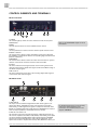
\B E D I E N E L E M E N T E
>>>>>>>>>>>>>>>>>>>>>>>>>>>>>>>>>>>>>>>>>>>>>>>>>>>>>>>>>>>>>>>>>>>>
INSTALLATION
Content of the Box
The unit was packed carefully. Nevertheless we recommend to check the
content directly after opening the package:
1 x MC-4
1 x Power cable
4 x Rubber feet
1 x Manual
1 x Registration card
The condition of the packaging material
and the device should be checked carefully
additionally. If there are any damages please
refer to SAFETY INSTRUCTIONS, Initial
Operation, and WARRANTY REGULATIONS.
Placing the Device
The unit should be set up as closely as possible to the devices to which it
will be connected, so as to avoid excessive cable lengths. Use the 4 rubber
feets enclosed with the appliance and stick them symmetrically on the
bottom side of the unit to protect the enclosure and supporting surface
from being damaged.
The device can be mounted into a standard 19“ rack and will require 1 unit.
In this case, the rubber feet cannot be attached. Install the device so that
one unit of rack space is left free both above and below the device to allow
for sufficient ventilation! The mounting depth including the terminals is
160 mm/6.7“. Another 60 mm/2.4“ should be added for the required cables.
Additional slide-in rails on the rack inside are recommended for safe installation. This will also avoid long-term mechanical deformation of the housing.
Before installing the unit the section
SAFETY INSTRUCTIONS located
at the beginning of this manual
should be read carefully.
!
Never expose the device and
accessories to rain, moisture,
direct sunlight, or excessive heat
produced by radiators, heaters, or spot
lights! Sufficient air circulation in the
environment of the device must be ensured!
!
Wiring the ADATTM, AES/EBU and S/PDIF interfaces
ADATTM
Connect the optical ADAT™ interfaces with the help of TOSLINK™-compliant optical fiber cables. Here, you can use both plastic and glass fiber-based
cables. When using plastic fiber cables, lengths of 10 meters should not be
exceeded, so as to ensure the reliable transmission of signals. Glass fiber
cables can transfer data reliably even over greater distances.
AES/EBU
Connect the AES/EBU interface with the help of an electrical 25-cond. cable
equipped with 25-pin D-Sub connectors. The specifications stipulate a specific cable resistance of 110 Ω. When purchasing the cable ask your retailer
for a confirmation that the cable will perform flawlessly in your specific
application.
Connect the coaxial S/PDIF interfaces with help of unbalanced electrical
cables equipped with cinch connectors on both ends. The specifications
stipulate a specific cable resistance of 75 Ω. Ask your retailer for a confirmation of this value when purchasing the cables.
Wiring the Word Clock Interfaces
To allow for the synchronization of signals, the interfaces of all devices
involved must be properly connected to each other, so as to ensure a logical
signal flow. Always be sure to connect the Word Clock output of the MC-4
to the corresponding input of the device you wish to synchronize. Cable
lengths should be kept as short as possible to minimize signal losses and/or
interferences!
For the transmission of Word Clock signals electrical, unsymmetrical cables
with a resistance of 75 Ω and BNC connectors on both ends are used. Typically, such cables are marked »RG-59U, RG59B/U«.
Additionally, you should make sure that the Word Clock input to be connected to the MC-4’s output have a 75 Ω terminating resistor! Most Word
Clock inputs allow for enabling/disabling the termination with a so-called
»termination-switch«, which may be located on the outside or inside of the
device.
MUTEC offers optical cables of various
lengths that have been specifically tested for
the transmission of ADAT™ signals. Ask your
local dealer for those cables!
We advise you not to buy 25pin
D-Sub cables from your computer
retailer! Even though such cables
may look similar to 25pin D-Sub AES/EBU
cables, they may be wired differently!
!
MUTEC assumes no liability for damages
resulting from the use of improperly wired
cables!
Especially when working with high AES/EBU
clock rates well shielded cables are imperative
to avoid increased radiation! Standard cables
are normally useable for clock rates up to
50.0kHz. Special shielded cable material
should be used for transfer of higher clock
rates.
Please make sure that the cable
used has a resistance of 75 Ω! If a
cable with a different resistance is
used, a dramatic deterioration of the signal
quality can be the result! In this case, the
perfect synchronization could be impaired.
!
We recommend using high-grade cables with
a good shielding. A length of max. 10 meters
(approx. 30 feets) should not be exceeded!
> > > > > > > > > > > > > > > > > > > > > > > > > > > > > > > > > > > > > > > > > > > > > > > > > > > > > > > > > > > > > > > > > > > > 88
11