1
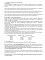
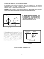
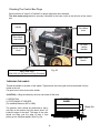
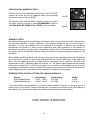
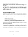
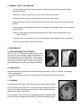
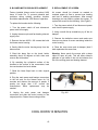
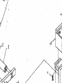
THE WINSTON GROUP LTD
1092 Carolina Drive, Suite 1
West Chicago, Illinois 60185
www.winstongroup.com
Phone:1-630-231-0419
Fax: 630-231-0429
OPERATING INSTRUCTIONS FOR THE
EAGLE V42-DD HOT-AIR WELDING TOOL
CONGRATULATIONS! You have purchased an Eagle, a tool that is designed and manufactured to assist
you with a quality seam weld. NOTE: The Winston Group does not warrant seam performance. We supply
a tool which provides heat, speed, and pressure. You, as the operator, select the correct combination of
these three components and, like all tools, the most important factor to a quality seam is your skill and
experience in setting up and using the Eagle.
WARRANTY CARD. A postage-paid warranty card is included in the shipping box. Please fill it out so that
we can provide you any new product information or "tips" for better welding. The serial number of your unit
is located on the handle of the gun assembly.
READ THESE INSTRUCTIONS
Any new tool requires familiarity. Take
fifteen minutes of time to
get
acquainted with your purchase. These
instructions are intended to guide you
through connection, operation, trouble
shooting, and maintenance. If you have
any questions or problems in start-up,
give us a call at:
1-630-231-0419
[email protected]
Fig. #1
COOL DOWN 10 MINUTES
CAUTION AS V42DD MOVES BACKWARD
I. UNPACKING, ASSEMBLY AND CONNECTION .
A. UNPACKING.
Your new V42DD Hot Air Welder is delivered to you in a sturdy, reuseable polymer tool box. The custom
designed foam base and spacers assure that your machine is protected and arrives ready to assemble
and use.
Remove the machine by lifiting it straight up and out and set it on a horizontal surface. The 2 additional
10 lb. weights are packed in cut-outs under the machine with foam covers on top.
Remove the foam covers from the weights and place them into the cut-outs for reuse after removing the
weights. Return all of the foam pieces to the box for later use during transportation and storage.
The only assembly required is to thread the handle into its base on the frame and tighten it down with the
lock nut, and attach an appropriate twist-lock plug to the end of the cord as described below.
B. ELECTRICAL POWER REQUIREMENTS.
Rating: 230VAC at 20 AMP The Eagle will operate within a range of 210VAC to 250VAC. Checking the
voltage at the point of unit plug-in is critical to the performance of your welder. You can perform the
voltage check with built in voltmeter.
Caution: YOU ARE WORKING WITH HIGH VOLTAGE EQUIPMENT. DEATH OR SERIOUS INJURY
MAY OCCUR DURING OR AFTER EQUIPMENT CONNECTION. UTILIZE A QUALIFIED
ELECTRICIAN.
Generators: Minimum 7,500 Watt Portable Generators should be used as a power source for each Eagle
V42DD automatic unit in use. Building electrical outlets are a poor source of voltage because they are too
unpredictable. Even when they are dedicated circuits, power spikes and drops can occur, resulting in
sub-standard equipment operation.
A Minimum 7,500 Watt watt capacity for the generator provides a measure of protection against
insufficient voltage. Remember, the Eagle utilizes 4,200 watts so the guage and length of your extension
cord will affect the wattage requirement.
Extension Cords: Extension cord should be at least 10 Gauge, 3 wire, grounded cable.
Do not splice lengths of cable together. This is a serious safety hazard, and can cause a poor connection,
resulting in sub-standard machine performance. Maximum Extension Cord Lengths:
Voltage @ power source
208VAC
220VAC
230VAC
240VAC
10 Gauge, 3 wire
12 Gauge, 3 wire
100 Feet
50 Feet
300 Feet
100 Feet
400 Feet
200 Feet
500 Feet
300 Feet
C. PLUG CONNECTION.
A Three-prong(L6-30) Twist Lock plug with a rating of 30 Amps and 250VAC is required.
Eagle is shipped with a L6-30 plug (Part#HBL2621). An extension cord is required between generator
and eagle. A plug and receptacle with a rating of 30 Amps and 250VAC must be purchased and properly
installed. The purchased plug must fit the generator outlet (usually L14-30).
100 feet 10 gauge, 3wires extension cord furnished with L14-30 Plug and L6-30 Receptacle can be
purchased with the Eagle Unit. (Part#10-3-100)
The white and black wires from the cord set of the welder must be connected to the appropriate "X" and
"Y" terminals in the plug to obtain the proper voltage. The green wire must be connected to the ground
terminal of the purchased plug.
The voltmeter on the control box must read 210 Volts as a minimum and 250 Volts as a maximum
-2for proper operation.
D. ADDING THE WEIGHT KIT, AND CHECKING THE NOZZLE.
If recommended by the membrane manufacturer, add the 20 pound weight kit. Most membrane
manufacturers require the weights for welding. The amount of weight is a function of the type of
membrane, the type of insulation material and its thickness.
Weight Kit:To add the weight kit, simply slide the two weights over the preinstalled pins on the platform
over the pressure wheel. A third 10 pound weight (Part# 8622) may be added if required.
A- Welding Nozzle-Offset Alignment. Check
the distance between the vertical centerline of
the compression roller and the tip of the nozzle.
The distance should normally be 21/4"-21/2" (5560mm) from the centerline of the roller.
Compression
Wheel
Nozzle
21/4" - 21/2"
Fig. #2A
B- Welding Nozzle In-line Alignment: Check the
alignment of the welding nozzle to the compression
wheel as shown in Fig. #2A. The inside edge of the
compression wheel should be in line with the inside
edge of the throat of the welding nozzle as shown
in Figure #2B. Proper alignment of the welding
nozzle to the compression wheel is accomplished
by adjusting the thumb wheel (Illustration #23 on
the part sheet) on the frame of the unit.
Compression
Wheel
Fig. #2B
COOL DOWN 10 MINUTES
-3-
Nozzle
Checking The Control Box Plugs
Each connector is "keyed" or "indexed" for proper alignment when attached.
The drive motor plug should be securely connected to the lower outlet on the left side of the control
box.
Handle
Drive Motor
Lever
Drive Motor
connection
AC Input
Voltage
Indicator
Speed Control
Knob
Main Power
Switch
Fig. #3
Main Power Input
30A 250V (L6-30)Twist-Lock Plug Furnished
THREADING THE HANDLE.
Thread the handle to the back of the welder. Tighten down the locking bolt so that the handle is firmly
bolted to the unit.
Put gear lever to drive to move the welder.
(CAUTION) - Lifting the welder by the lever can break off the lever.
II. OPERATION
A. POSITIONING OF WELDER
(For modified Bitumens APP or SBS)
COMPRESSION
WHEEL
Bleed-Out
The pressure roller should be positioned so that it
rolls fully on the surface of the top sheet, about 1/4"
inside the edge of the shelf. The edge of the roller
should not hang over the edge to keep it from
picking up the liquefied asphalt. (See Fig. #4).
Fig. #4
-4-
0.25"
SEAM STARTUP, WINDOW OF WELD.
With the unit up to set temperature put the gear lever into "DRIVE",
position the nozzle tip into the membrane seam and immediately
turn the drive motor switch to "START".
The operator must assist the welder, guiding it down the length of
the seam. Since the operator is walking BACKWARDS on the roof,
CAUTION MUST BE TAKEN AT ALL TIMES for his own safety.
Fig. #5
Fig. #6
WINDOW OF WELD
The Winston Group does not warrant seam performance. Only you can control and verify a quality seam.
The operator's selection of speed, temperature, and pressure (weight kit) will vary with the type of
membrane, its color, the substrate, and the conditions of the jobsite. In addition, your membrane
manufacturer will provide you with a correct temperature and speed guidelines. In the selection of
temperature and speed, the experience of the operator and the advice of the membrane manufacturer are
the primary sources of information. Always conduct test welds to determine the required settings for the
membrane.
When welding modified bitumens insert the hot nozzle between the overlapping seam and immediately
turn the drive motor switch on. Observe the melting and bleed-out of the liquid bitumen at the edge of the
seam. With 20 additional pounds of weight and the temperature set at maximum (setting 9 gives
approximately 1200°F), adjust the speed until a uniform 1/4"- 3/8" bead of liquid asphalt forms at the edge
of the seam. (Usually about 10 FPM Feet per minute. One revolution of wheel equals one foot of travel.)
Increasing the temperature slowing the speed and increasing the pressure will all increase the bleed-out.
A third weight may have to be used for heavy membranes or thickness in cold weather.
REPRESENTATIVE CONTROL SETTING FOR VARIOUS MATERIALS*
Material
APP Modified Bitumen
SBS Modified Bitumen
Heat Settings
1100°F - 1200°F
1100°F - 1200°F
Speed Setting
8-12 FPM
8-12 FPM
Weight
0-30 lb.
0-30 lb.
*The values shown are representative for "normal" ambient weather conditions and provided only as a
starting point for test welding. Clements National does not warranty the weldability and seam strength of
any material. The end user must conduct test welding to determine actual control settings.
COOL DOWN 10 MINUTES
-5-
SHUTTING DOWN THE WELDER. (10 MINUTES COOL DOWN)
First, remove the nozzle tip while the welder is still in motion by positioning the nozzle tip in an "UP"
position, pointing into the air. Switch the Drive Motor to "STOP" and put the drive gear lever to
"FREE WHEEL".
DO NOT TURN THE TOOL SWITCH OFF UNLESS YOU HAVE ALLOWED THE GUN TO "COOL"
DOWN. Failure to cool the gun prior to turning the power off may cause damage to the unit's
heating element and/or internal components. Make sure that the heat of the resting nozzle tip is
not pointed in the direction of the weights. Leaving the heat gun in the down position will cause
damage to the compression roller.
SEAM VERIFICATION FOR MODIFIED BITUMENS.
At the beginning of a day's seam welding, the operator of the unit must always perform destructive seam
analysis to make sure that he has selected the optimum mix of the temperature, speed and pressure for
his welder, and the particular membrane.
This seam analysis should be performed at the beginning of a day's production, and at any significant
change in operating environment, such as:
• A ten degree (F) change in ambient temperature.
• A significant change in cloud coverage.
• A moderate change in wind conditions (10MPH).
• A moderate change in humidity (10%).
• A noticeable change in the speed of the drive (indicating a significant change in voltage).
• Movement from a major shaded area to a major sunny area, or vice versa.
The operator should select a mix of speed, weight and temperature that is conservative, that is, he should
never run the welder at the "high edge" of welding. There should be a minimum of a 20% margin of safety
against peak speed and temperature mix.
The operator should be cautious of poor welds where there is a change in plane of the substrate surface.
For example, where there is a seam along the edge of a raised insulation board or where a fastener plate
is located too close to the edge of the seam, there may be insufficient compression of the seam.
Start and stop points in a seam are especially vulnerable to cold weld, so these should be marked and
checked carefully.
COOL DOWN 10 MINUTES
-6-
III. GENERAL SAFETY INFORMATION.
• You are working with high voltage equipment. Always disconnect the power source before
servicing the welder.
• Never pull or carry the welder by a power cord or electrical connection.
• Keep clear of the heat gun nozzle. Exposed skin will burn upon contact.
• Always heat seam in a well-ventilated area. Do not inhale fumes caused by the heat seaming
process.
• Do not operate near flammable materials. Do not apply any flammable liquids to the surfaces to
be heat seamed.
• Always cool the heat gun down before shutting off the master switch. Always cool the unit
before storage.
• Protect the unit from exposure to rain. Do not weld when water is standing on the membrane.
• Call if you have questions, call 630-231-0419
IV. MAINTENANCE
A. HEATING ELEMENT REPLACEMENT.
(See Fig. #7 & 8). Disconnect power source. Make
sure the unit has thoroughly cooled. Replacement of
the heating element is accomplished by removing the
four screws at the base of the heat gun nozzle. Before
inserting the element, make sure that you align the
pins according to key marks on the element and base.
Fig. #7
Fig. #8
B. LUBRICATION.
Lubricate the following areas once a month with a light lubricating oil (LPS-2 or WD-40, for example):
• Drive axle bushings;
• Pivot shaft of heat gun (remove set screw, spring, and ball and spray directly into hole).
• Chain.
C. CLEANING.
Fig. #9
Use wire brush at the end of each 100 foot seam to keep nozzle foot clean.
Check and clean Air Intake screen on back of heat gun handle at least twice
a day. Dust and lint will clog the screen. Brush out with a small soft brush,
and rotate the baffle. (See Fig. #9)
Do not operate unit with intake screen damaged or missing. Material drawn
into the heat gun can damage the impellers, controls and heating element.
-7-
D. BLOWER MOTOR BRUSH REPLACEMENT
E. REPLACEMENT OF SCREEN.
Factory installed blower motor has about 1400
hours of brush life. To prevent potential stall
problems during welding operation brushes
should be replaced after 1000 hours of operation.
Air screen should be cleaned as needed to
maintain proper air flow to prevent over heating
and loss of welding performance. After several
cleanings you may need to replace the screen. To
replace the screen do the following: (See Fig#10)
To replace the brushes do the following:
1. Turn the power switch off and disconnect
power cord from supply.
2. Unplug thermocouple and fan-heating element
supply cord.
1. Turn the power switch off and disconnect power
cord from the power supply,
2. Using a small flat tip screwdriver pry off the air
damper,
3. Remove the two #8-32 x 3/8 screws that hold
the blower motor housing.
3. Remove the defective screen and make sure
there are no pieces of screen remaining inside the
motor housing,
4. Gently slide the motor housing away from the
blower motor.
4. Place the new screen and air damper (best if
both replaced at the same time,
5. Bend the brass flap on the brush holder
assembly about 90 degrees at both sides and
remove the old brushes.
Warning: Never punch the screen with a sharp
object to open air path. This will allow airborne
particles to get inside of the unit and shorten the
life of the moving parts and heating element.
6. By matching the cylindrical surface of the
brushes to the surface of the commutator, load
the new brushes into brush holder.
7. Bend the brass flaps back to their original
position.
8. Plug the main power and heatgun connectors
to the unit and run the blower motor for 3-4
seconds and observe the amount of sparks. If
sparks are larger than 1/16" consult the
manufacturer. Motor replacement may be
needed.
9. Unplug the main power and heatgun
connectors and slide the motor housing to the
original position. Fasten the mounting screws.
Fig. #10
COOL DOWN 10 MINUTES
-8-
V. TROUBLE SHOOTING TIPS
POOR WELD .
1. Check power source for 200 to 240 VAC.(See Fig. #3)
2. Check and/or replace heating element.
3. Gun tip not properly aligned at 2-1/4"-2-1/2'.
4. Additional weight required to compress lap.
5. Incorrect relationship between speed and temperature. Consult membrane manufacturer.
You may be moving too fast for your temperature setting.
NOZZLE COMES OUT OF SEAM
1. Tighten Lock Screw on the frame. (Illustration #23 on the part sheet)
UNIT "JERKING"
1. Check for low voltage on the control box voltmeter.
(See Fig. #3 Should be 210 to 250 VAC )
2. Check drive engage/disengage gear lever.
3. Increase speed setting slightly higher. One revelution of the compression wheel equals
one foot of movement. One revelution in 6 seconds equals 10 feet a minute.
SEAM
1. Too much heat, lower temperature setting.
2.Adjust speed (one revelution of wheel equals to 1 foot)
3. Use least amount of weights. Start with no weights and add-remove weights as required
for best results.
Call 1-630-231-0419 for help or e-mail [email protected]
COOL DOWN 10 MINUTES
-9-
Warranty
HOT AIR WELDER
This product has been manufactured and engineered to the highest performance standards and has
been subjected to testing prior to shipment.
ONE YEAR WARRANTY
THE WINSTON GROUP guarantees this product against defects in material and workmanship for a
period of ONE YEAR from the established purchase date. The Winston Group. will repair or replace,
free of charge, any defective parts determined to be covered under this warranty by factory authorized
service personnel. Labor to install these parts will be supplied at no charge during this one year period.
The complete unit or defective module must be returned to a factory authorized service center, freight
prepaid, preferably with a letter of explanation.
CONDITIONS
This warranty does not apply if the unit has been misused, altered, or used for any purpose other than
in accordance with the operating instructions provided. This warranty does not cover transportation,
exterior finishes, heating elements, silicone wheels, or carbon motor brushes.
Operation of these units with other than factory original parts shall render this warranty null and void.
This warranty replaces all other warranties expressed or implied.
THE WINSTON GROUP LTD
1092 Carolina Drive, Suite 1, West Chicago, Illinois 60185
PHONE: 1-630-231-0419
FAX:1-630-231-0429
www.winstongroup.com
-12-