1
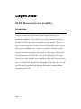
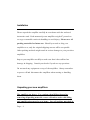
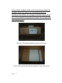
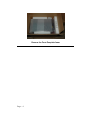
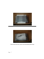
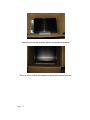
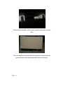
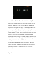
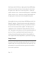
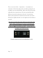
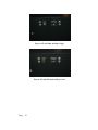
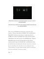
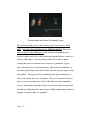
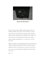
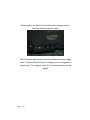
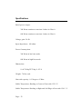
Clayton Audio M-300 Monaural power amplifier Truly Remarkable Amplifiers. Page - 2 Clayton Audio M-300 Monaural power amplifier Introduction Congratulations on your purchase of the Clayton Audio M-300 monobloc amplifiers! Your M300s were made to sound good and to perform as well as the very best amplifiers on the market. They are a high-current design that can drive the most demanding speaker loads. These power amplifiers were designed to produce reference-quality sound with all the excitement and elegance of live music. The M-300s were handmade in the USA after years of careful design and testing. Properly used and installed, these amplifiers will provide you with many years of trouble-free, high-quality amplification. We hope that you will take the time to read and look through this owner’s manual before operating the M-300. Page - 3 Installation Please unpack the amplifier carefully in accordance with the enclosed instruction card. Each monaural power amplifier weighs 87 pounds so we urge reasonable caution in handling to avoid injury. Please save all packing materials for future use. Should you need to ship your amplifier to us, only the original shipping cartons will be acceptable. Other packing methods might result in serious damage to your precision amplifiers. Inspect your amplifier carefully to make sure that it has suffered no damage in shipping. Consult your dealer if you have any questions. Do not stack any equipment on top of the amplifiers. Always remember to power-off and disconnect the amplifiers when moving or handling them. Unpacking your new amplifiers The amplifers are heavy. Use caution when lifiting them after removing all packing material, or use a friend to assist with lifting and amplifer placement in your home. Save all packing materials in Page - 4 the box. Below are photos of the series of steps used to unpack the amplifier. Please note that we use a special metal protector blocking the fuse holders, 12 volt trigger switch and remote control port. We recommend leaving this metal strip on the rear panel until removal is necessary. Carefully cut through the taped top center and top sides Lift the cardboard flap exposing the top layers of foam and remove. Page - 5 Remove the Front Faceplate foam. Page - 6 Remove the side foam, power cord and antistatic plastic wrap Page - 7 Carefully remove the antistatic plastic and protective material This is a photo of the front faceplate cleared after removal of foam. Page - 8 Carefully lift the amplifier with the rear protection attached to remove later. Once the amplifier is placed near the final position, remove the rear panel protection and remove the tape from the connectors. Page - 9 Operation The Clayton Audio M-300 monoblocs are high-performance class A amplifiers, conservatively rated at 300 watts per channel into 8 ohms. They are a no-compromise, wide-bandwidth design which should drive virtually any high-end speaker load with relative ease. Because the Clayton Audio M-300s are a class A design, they will run very hot in normal operation. Make sure to place them in a well-ventilated location on a stable support. Be careful about touching the tops of the heat sinks when in operation. Depending on the AC line voltage the high-bias setting will run at a temperature up to 55 degrees Fahrenheit above the room temperature. The low-bias setting will only run about 40 degrees above room temperature. Under casual listening conditions, the low-bias setting will be virtually indistinguishable from the high-bias setting and will not make the amplifier run as hot. The bias switch can be set to high when listening critically or at high volume levels. Since the amplifier is very stable, you can switch between the two bias positions at any time, even while the amplifier is in operation. See photo below. Page - 10 The Power Switch in On and the Bias Mode is on High Bias. Each Clayton Audio M-300 has three fuses, easily accessible from the rear panel. All fuses are 5 amp, Fast Blow (FB) types which must be replaced with fuses of the same value. To examine and replace a fuse, make sure the amplifier is powered down, remove the fuse protector plate and then simply push in the rear knob (nut) of the fuse and turn it counter-clockwise to release. This is the only repair that the user should attempt to make. If you are experiencing any problems with the amplifier that cannot be solved by replacing the fuses, call your Clayton Audio Dealer immediately. The toggle switch is the 12 volt trigger. The default position is in the down or “OFF” mode. DO NOT OPEN THE AMPLIFIER if there is any problem. You should contact your Clayton Audio dealer immediately. Any attempt to open and/or tamper with the M-300 amplifiers will void the warranty immediately. Page - 11 Each Clayton Audio M-300 has two high-quality German WBT binding posts that accept either spade lugs or banana plugs for connection to the speaker wires. Make sure to connect the positive (+ usually red) speaker connector to the + connection and the negative (- usually black) speaker connector to the - connection on both the right amplifier and the right speaker. Do the same for the left amplifier and speaker. Each amplifier also has a precision German WBT XLR input jack for True Balanced™ operation. Connect the audio source’s right output jack to the right monobloc’s XLR input jack using a good quality interconnect. Do the same for the left monobloc amplifier. The balanced pin-out configuration is: Pin 1=Ground; Pin 2=Positive (Hot); Pin 3=Inverted 180°. Our ground is to the chassis as well as the ground through the AC power cord. There is a gold plated knurled ground connector for assisting with potential ground loop problems with preamplifiers or other equipment that utilizes Single Ended or quasi balanced topology. Design Concept The Clayton Audio M-300’s are high current differential True Balanced™ amplifiers using class A design in both the driver and output stage. All gain transistors are operated in their linear region for the smoothest, purest sound reproduction. Page - 12 There are two levels of bias --- high and low --- for maximum user convenience. The low bias setting can be used when operating the unit in standby or for non-critical listening. Indeed, since the low bias setting still provides class A operation up to 200 watts, you should hear little difference between the settings most of the time. For the absolute highest quality reproduction of dynamic material and the most critical listening, the amplifiers should be set to the high bias level for full class A operation. The power-on and bias select mode switches are a high quality rocker switches hidden underneath the front center front face plate at the bottom. You will feel two switches. The larger POWER ON switch is located on the right of the smaller BIAS switch. The BIAS switch is next to the left of the POWER On switch. . This photo shows the Amp On and the Bias Mode on LOW. Page - 13 Amp is off and bias setting is high. Amp is off and the bias setting is low. Page - 14 Both Rocker switches are towards the faceplate, the amp is on and in HIGH BIAS MODE. When the Rocker switch on the left is pressed towards the rear, the amp is in LOW BIAS MODE. There are two red LED indicator lamps on the center front of the faceplate. The lower lamp indicates POWER ON. The top LED indicates BIAS MODE. The bottom lamp will glow at Full Intensity when the POWER is ON. When the LOW BIAS mode switch is OFF, the top LED LAMP indicator is the same intensity as the POWER ON lamp. When the BIAS MODE switch is on, the TOP Lamp with glow half as intense indicating that the amp is in LOW BAIS Mode. LOW BIAS Mode allows the M-300 to run cooler and produce 200 watts. Many listeners keep the amp on continually in this mode, only to switch to FULL Power when critically listening. We suggest turning the amps off when not listening to music for extended times, or leaving your home. Page - 15 Front LED Power and Bias Lamp Indicators The Power On Lamp is located on the bottom with Bias Mode lamp above. For safety, we have built into the Clayton Audio design a power on lamp on the rear panel. Please make certain that the glowing RED LAMP IS OFF on the front face plate and OFF on the rear before connecting or disconnecting any cables. See Photograph below. Page - 16 The rear panel with Power On Indicator Lamp. The four long bumpers at each corner of the rear panel are NOT FEET. DO NOT STAND THE AMP ON THESE BUMPERS. These are Clayton Audio Safety Bumpers™ and will prevent bending your favorite cables and power cable when moving the amp too close to a wall or solid object. As these amps produce heat, please make certain they are not located next to drapery or furniture. If you place the amps into a rack system they will need at a minimum of 24 inches of proximity clearance at the sides and top for proper heat dissipation. The amps are best sounding when placed directly on their own custom feet on a solid floor. There is no need to invest in fancy cones or special pucks as feet. The Clayton Audio amplifier feet are machined extra tall to allow air current to flow underneath the chassis when placed on most carpets. High quality amp stands or granite or marble slabs are optional. Page - 17 Clayton Audio Rear Bumpers The power supply contains a 2KVA toroidal transformer with up to 200,000 microfarads of capacitance. The M-300 makes use of dual separate power sources for the driver and output stages. The driver stage incorporates a high-precision regulation circuit for stability. The output stage is an extremely high current design using a filter to enhance stability and minimize noise. No capacitors are used in the signal path. Both power supplies are symmetrically balanced in positive and negative voltage to eliminate any possible instability caused by powering the amplifier on and off. A precision power-on sequence control circuit is also used to prevent any damage that might be caused by the initial power surge. Page - 18 Please replace the Rear Fuse Protector after changing fuses or selecting remote modes for safety. The Fuse Panel and Remote Control and Remote Selector toggle switch. Remove this panel prior to changing over to a triggered or remote input. The toggle is in the Off, Local down position as the default. Page - 19 Warranty Clayton Audio warranties your M-300 monobloc amplifiers against any defects in design or manufacture for three years from the date of purchase. Defective units will be repaired within the warranty period without charge for labor or parts assuming that the units have not been altered or damaged through abuse, negligence, deliberate modification, accident or improper operation. All repairs must be directly undertaken by Clayton Audio. We ask that you ship the defective amplifier(s) to us, after proper authorization. You are responsible for the one-way shipping and insurance expenses and we will cover return shipping costs. Equipment must be returned in the original boxes with the original packing material along with a copy of the sales receipt from an authorized dealer. This warranty is transferable from the original owner to future purchasers with proof of resale and any subsequent owner will receive the remainder of the three- year warranty from the date of the original purchase. You are responsible for mailing the enclosed warranty registration card. This officially registers your unit and permits us to inform you of any upgrades or improvements that we may offer. You may also receive new production information from us. Your name and address will never be Page - 20 sold for use in general mailing lists and is only for our own internal records. Clayton Audio reserves the right to make improvements to their design occasionally is deemed necessary. Page - 21 Specifications Rated power output: 300 Watts continuous rms into 8 ohms in Class A 600 Watts continuous rms into 4 ohms in Class A Voltage gain: 26 db Input Impedance: 100 ohms Power Consumption: 300 Watts in low bias mode 800 Watts in high bias mode Dimensions: 11.00” W by 20” D by 11.50” H Weight: 70 lbs. each. Heat sink capacity: 0.13 degrees C/Watt Stable Temperature Reading at Center of heat sink: 122.1° F. Stable Temperature Reading at Right and Left Edge of heat sink: 124.1° F. Page - 22 Page - 23 Contact Information: Clayton Audio 8151 Stratford Ave. Clayton, MO 63105 Phone: 314-862-6017 Fax: 314-862-0765 Dealer Sales, Marketing, Technical Support: TRI Audio Marketing 13604 Hartsbourne Drive, Suite 101 Germantown, MD 20874-2828 Email: [email protected] Phone: 301-540-1156 Fax: 301-916-1772 ***** Version 2.1 Page - 25