1
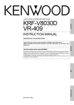
UHF FM TRANSCEIVER
DJ-S446
Instruction Manual
Thank you for purchasing this ALINCO FM
transceiver.
This instruction manual contains important safety and
operating instructions.
Please read it carefully before using the transceiver
and be sure to keep it for future reference.
ALINCO, INC.
Contents
Contents
■Points to Note when Using an External Power Supply
1. Accessories .......................................................2
1-1 Standard Accessories .......................................................... 2
1-2 Attaching and Detaching Accessories ................................ 2
1-2-1 Hand Strap .................................................................... 2
1-2-2 Belt Clip ....................................................................... 2
1-2-3 Battery Pack ................................................................. 3
1-3 Battery Level Indicator ....................................................... 4
1-4 Loading Batteries ................................................................ 4
2. Control Functions ............................................. 5
2-1 Names and Operations of Transceiver Controls ................. 5
2-2 Key Operations ................................................................... 7
2-3 Display ................................................................................ 9
3. Basic Operations ............................................ 10
3-1 Turning the Power ON ...................................................... 10
3-2 Adjusting the Audio Volume ............................................ 10
3-3 VFO Mode ........................................................................ 10
3-3-1 Frequency Number Setting ......................................... 10
3-4 Memory Mode .................................................................. 11
3-4-1 Selecting a Memory Channel ..................................... 11
3-4-2 Memory Channel Programming ................................. 12
3-4-3 Clearing a Memory Channel ...................................... 13
3-4-4 Contents of Memory Programming ............................ 13
3-5 CALL Mode ...................................................................... 14
3-5-1 Selecting the CALL Channel ..................................... 14
3-5-2 Programming a CALL Channel ................................. 14
3-6 Receiving .......................................................................... 15
3-6-1 Monitor Function ........................................................ 15
3-7 Transmitting ...................................................................... 16
3-7-1 Selecting the Transmitter Output Level ..................... 16
i
Contents
4. Parameter Setting Mode .................................. 17
4-1 Mode Setting Items ........................................................... 17
4-2 Selecting the Setting Mode ............................................... 18
5. Advanced Operations ..................................... 22
5-1 Scanning ........................................................................... 22
5-1-1 VFO Scan ................................................................... 23
5-1-2 Memory Scan ............................................................. 23
5-1-3 Skip Channel Setting .................................................. 24
5-1-4 Tone Scan ................................................................... 24
5-2 Key Lock .......................................................................... 25
5-3 Tone Call ........................................................................... 25
5-4 Lamp ................................................................................. 25
6. Selective Communicating ............................... 26
6-1 Tone Squelch .................................................................... 27
7. Special Functions ........................................... 28
7-1 Theft Alarm ....................................................................... 28
7-1-1 Connecting and Setting .............................................. 29
7-1-2 Alarm .......................................................................... 30
7-1-3 Alarm Delay ............................................................... 31
8. Cloning ............................................................. 32
8-1 Cloning ............................................................................. 32
9.Maintenance and Reference ........................... 35
9-1 Resetting ........................................................................... 35
9-2 Options .............................................................................. 36
10.Specifications .................................................37
ii
iii
Before Operating the Transceiver
Caution
The use of a transceiver in the following places may be prohibited.
• Aboard aircraft •In airports •In ports •Within or near the operating area of
business wireless stations or their relay stations.
Before using the transceiver in any of the above places, obtain any necessary
permission from the proper authorities, and be mindful of local laws that govern
amateur radio operation.
■Points to Note when Using an External Power Supply
• Use a 4.5V-16.0 DC external power source.
• When connecting the power supply to the transceiver, use the optional DC
cable for base stations (EDC-37). Connect the cable to the DC jack on the side
of the transceiver.
• When power is supplied from the cigarette lighter socket of a car, use the
cigarette lighter cable (EDC-43) or the cigarette lighter cable with filter (EDC36).
Use the cigarette lighter cable with filter (EDC-36) during mobile operation
to help prevent noise.
• Turn the transceiver's power off when connecting or disconnecting the DC
cable.
1
1. Accessories
1. Accessories
1-1 Standard Accessories
• Battery Case EDH-31
• Belt Clip
• Hand Strap
• Instruction Manual
(Note : Standard accessories may vary depending on versions.)
1-2 Attaching and Detaching
Accessories
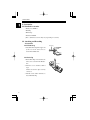
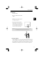
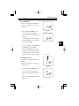
1-2-1 Hand Strap
Hand Strap
1. Attach the hand strap in the upper slot
(at the rear of the transceiver) as
shown in the illustration.
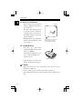
1-2-2 Belt Clip
1. Put the Belt Clip on the back of the
transceiver as shown in the illustration.
2. Turn the screw clockwise until it
stops.
Check to be sure the clip is securely
connected.
3. Turn the screw counter-clockwise to
detach the Belt Clip.
2
Belt Clip
1. Accessories
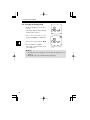
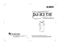
1-2-3 Battery Pack (Option)
1. Attaching the battery pack:
Align the grooves on the battery pack
with the rib on the transceiver, and
push in the direction of the arrow
until it clicks.
2. Detaching the battery pack:
Push down the catches at the bottom
of the transceiver, and slide the
battery pack off in the direction of
the arrow.
Battery Pack
Rib
Groove
Battery Pack
Catches
2
1
Caution
• The battery pack is not charged when shipped. It must be charged before using.
• It takes a maximum of 10 hours to charge the battery pack with the EDC-93
(120V) / EDC-94 (230V)(EBP-52N / EBP-53N) and about 30 hours with the
EBP-54.
• Charging should be conducted within a temperature range of 0 to 40˚C.
(32-104˚F)
• Do not convert or dismantle the battery pack and do not place it in fire or water.
Such practices are dangerous. Never short-circuit the battery pack terminals, as
this can cause damage to the equipment or lead to overheating the battery, which
could cause burns. Unnecessary prolonged charging (overcharging) can
deteriorate battery performance.
• The battery pack should be stored in a dry place where the temperature range is
-20˚C to -45˚C (-4˚F to +113˚F).
Temperatures outside this range can cause battery liquid leakage. Exposure
to prolonged high humidity can cause corrosion of metal components.
• Normally, the battery pack can be charged up to 500 times. However, the battery
pack can be considered dead if usable time drops off markedly in spite of charging
the pack for the recommended time. When this happens, a new pack should be
used.
• To protect the environment, do not dispose of the used battery pack improperly.
Check with your local solid waste officials for details on recycling the battery
pack for proper disposal in your area.
• To charge the battery pack, mount it on the transceiver, connect 13.8VDC to the
DC power supply jack and set the unit's battery charging function ON in the
Setting mode.
3
1. Accessories
1-3 Battery Level Indicator
• Battery charge level may change in
relation to ambient air temperature or
the amount of use.
• Even if the charge indicator appears
to show the need for charging or
replacing batteries, the transceiver
may still be used for reception or low
output transmission.
• Modify the battery type setting in the
Setting mode when the battery pack
type is changed.
Charge Level
When the charge level becomes low,
an empty battery mark appears.
Charge (or replace) the battery.
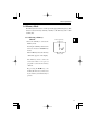
1-4 Loading Batteries
1. Load three (3) commercially
available AA alkaline batteries in the
battery case (EDH-31).
Set the batteries in the battery case in
the +/- orientation marked at the
bottom of the case.
Battery Case
2. Attach the battery case in the same
method of the battery pack (page3).
Caution
• Manganese batteries are not recommended as they may decrease the
transmission output level.
• Be sure to observe proper orientation of the batteries polarity (+ -).
• Switch off the battery transceiver's charge function when dry cell batteries are
used.
4
2. Control Functions
2. Control Functions
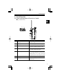
2-1 Names and Operations of Transceiver Controls
■ Top and Front Views
4
3
1
1
2
5
6
7
No.
1
Name
Power Switch
Volume
Functions
Switches power ON/OFF. Also used to adjust
the audio volume.
2
Display (LCD)
Refer to "Display" in this manual (Page9).
3
MIC Connector
For connection of the optional external
microphone (2k Ω) with 2.5Ø stereo plug.
4
SP Connector
For connection of the optional external speaker
(8 Ω) with 3.5Ø monophonic plug.
5
FUNC key
Use this key in combination with other keys to
access various functions of the transceiver.
Holding this key for 3 seconds activates the
Setting mode where various settings are possible.
6
Key pad
Refer to "Key Operations" (Page7).
7
Microphone
Speak into microphone from a distance of
approx. 5 cm.
5
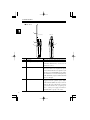
2. Control Functions
■ Side View
8
Antenna Side
Volume Side
9
11
10
No.
8
6
Name
Antenna
Functions
Pivot the antenna up when using the transceiver.
9
PTT (press to talk) key
When this key is held down, the transceiver
transmits. When the key is released, the
transceiver receives.
10
MONI key
When this key is pressed, the squelch is unmuted
and you can hear received signals. The squelch
is also unmuted when the tone squelch is set. If
this key is pressed while FUNC appears, the Key
Lock function is activated. Pressing this key
while the PTT key is pressed and held transmits
the tone call signal.
11
DC-IN
Terminal for connecting an external power
supply. Connect the optional cigarette lighter
cable with filter (EDC-36), and you can use it
in the car. The center of the pin is the + (positive)
pole and the outside is the - (negative) pole.
Use a stable power supply with DC4.5DC16.0V, with a capacity of 1A or more.
2. Control Functions
2-2 Key Operations
1
2
3
4
5
6
No.
1
Name
PTT
Independent operation
Completes the setting in
the setting mode.
After pressing FUNC key
-
2
MONI
Activates the monitoring
function.
Switches the key lock ON/OFF (page 25).
3
FUNC/SET
Accesses various
functions.
4
▲/T SQ
Increases the frequency
and memory channels.
Sets the tone squelch function (page 27).
5
▼/CALL
Decreases the frequency
and memory channels.
Activates the Call mode (Page 14).
6
V/M /MW
Switches VFO/Memory
modes.
Programs a memory channel (Page 12).
-
7
2. Control Functions
No.
8
1
Name
PTT
Pressed for a while
Enables transmission
while holding.
2
MONI
-
3
FUNC/SET
Activates the Setting
mode (page 17).
4
▲/T SQ
Starts upward scanning
(page 22).
Sets the transmission output level HIGH
(page 16).
5
▼/CALL
Starts downward
scanning (page 22).
Sets the transmission output level LOW
(page 16).
6
V/M /MW
-
During transmission
Transmits tone call signal (page 25).
-
-
2. Control Functions
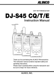
2-3 Display
1
2 3 4 5
6
7
8
9
12
11
10
13
No. Display
14 15
16
Indication
1
Appears when the FUNC key is pressed.
2
Blinks during memory writing mode.
3
Appears on Memory scan skip channel(s).
4
Appears when the Bell Function is on.
5
Appears when the charge level is low.
6
Appears when the Mosquito Repellent Signal (MRS) is ON.
7
Appears when transmission output level is LOW.
8
Indicates memory No. in the Memory mode and setting No.
in the Setting mode.
9
Appears when keys are locked.
10
Indicates the frequency number.
11
Indicates the tone number.
12
Indicates the various setting status.
13
Appears when the Theft Alarm is ON.
14
Blinks during scanning operation.
15
Appears when the squelch is unmuted.
16
Indicates the receiving level and the transmission output.
9
3. Basic Operations
3. Basic Operations
3-1 Turning the Power ON
Power switch
Hold the POWER switch down for a
second to turn the power ON. To turn the
power OFF, hold the power switch down
again for 2 seconds.
3-2 Adjusting the Audio Volume
To increase : Rotate the volume dial
clockwise.
To decrease : Rotate the volume dial
Audio volume
decreases
Audio volume
increases
counter-clockwise.
When a voice cannot be heard due to the
squelch setting, press and hold the MONI
key and adjust the volume to the level you
Volume dial
desire.
Reference:Squelch level can be adjusted in the Setting mode (page 17).
3-3 VFO Mode
The factory default setting for the
transceiver is the VFO mode.
3-3-1 Frequency Number Setting
When ▲/▼ keys are pressed, frequency
number increases and decreases.
10
VFO mode
3. Basic Operations
3-4 Memory Mode
The Memory mode is used to recall a previously programmed frequency. This
transceiver has 99 memory channels (1-99CH), 1 call channel (C), and 1 alarm
channel (SC).
3-4-1 Selecting a Memory
Channel
Memory channel No.
1. Press the V/M key to activate the
Memory mode.
Pressing the V/M key alternates the
transceiver between VFO/Memory
modes.
When in Memory mode, the memory
channel No. appears on the display.
Memory mode
The Memory mode cannot be
activated if there is no pre-set
program recorded in the memory
channels.
By pressing the ▲/▼ keys, the
memory No. increases (or decreases)
by one memory each time the key is
pressed.
11
3. Basic Operations
3-4-2 Memory Channel
Programming
1. Return to the VFO mode by pressing
the V/M key.
2. Select the desired frequency you wish
to save to Memory.
VFO mode
3. Press the FUNC key and then press the
V/M key while the "F" icon appears.
The memory channel No. and "W"
blinks.
4. Select a memory channel to program by pressing the ▲/▼ keys.
A blinking memory channel No. indicates that the channel is not
programmed yet.
5. Press the MW key while "W" blinks.
A beep is heard and the selected VFO frequency number is programmed
to the memory channel.
Caution
• Please be sure to set the frequency number for alarms in CH-SC (the
channel for alarms) (Page 29).
• Selecting and programming again overwrites a programmed memory
channel.
• The CALL channel can also be overwritten but the CALL channel cannot
be cleared.
12
3. Basic Operations
3-4-3 Clearing a Memory Channel
1. Press the FUNC key and then press the V/M key while "F" icon appears.
Memory channel No. lights and "W" blinks on the display.
2. Select a memory channel you wish to clear by pressing the ▲/▼ keys.
On a programmed channel, the "memory channel No." is displayed steadily
(without blinking).
3. Press the FUNC key again and then press the MW key while the "F" icon
appears.
A beep is heard and the pre-set frequency is cleared.
3-4-4 Contents of Memory Programming
The following information can be stored in each memory channel 1 - 99, SC
and the CALL channel.
• Frequency number
• Tone number
• Skip CH Setting
• Busy Channel Lock Out (BCLO)
13
3. Basic Operations
3-5 CALL Mode
The Call mode is used when you are receiving or transmitting on the CALL
channel. The transceiver has one CALL channel.
The default setting is "1-oF".
3-5-1 Selecting the CALL Channel
1. Press the FUNC key and then press the
CALL key while the "F" icon appears.
"C" appears on the display when the
CALL channel is selected.
2. Press the V/M key to return to the VFO
mode or the Memory mode.
Caution • Scanning cannot be performed when the transceiver is in the
CALL mode.
• In the CALL mode, frequency number or memory No. cannot
be changed by pressing the up/down keys.
3-5-2 Programming a CALL Channel
The CALL channel is one of the memory channels where the frequency number
and other settings can be programmed by selecting the memory channel "C" in
the VFO mode (page 12).
Caution : The CALL channel can be programmed but cannot be cleared.
14
3. Basic Operations
3-6 Receiving
1. Turn the power ON.
2. Rotate the volume dial to set the audio
volume.
3. Eliminate noise by setting the squelch in
the setting mode (page 17).
4. Select the desired frequency number.
When a signal is received on the selected
frequency, "B" appears on the display and
the received signal is heard. The S meter
indicates the relative signal strength.
S meter
Reference : Be sure to use the transceiver in the state where the antenna
is set straight up to the upper part of the transceiver.
3-6-1 Monitor Function
• While the MONI key is pressed, the squelch is unmuted and sound is heard from the
speaker regardless of the squelch setting. "B" appears on the display.
• By using this function, weak signals under the squelch threshold level can be heard.
• Monitoring the selected frequency can be done even when the tone squelch is set.
15
3. Basic Operations
3-7 Transmitting
1. Select the desired frequency number.
2. Press and hold the PTT key, speak into
microphone with normal loudness and
tone.
The S meter indicates the unit is in the
transmitting mode.
Speak into the microphone from a
distance of approx. 5cm.
3. Release the PTT key to stop transmitting and to return to the receiving mode.
Reference : A Tone call signal is transmitted by pressing and holding the
PTT key and pressing the MONI key (There are five tone call
signals that are selectable in the Setting mode).
3-7-1 Selecting the Transmitter Output Level
Transmission power can be changed to HI/LOW by pressing the ▲/▼ keys
while transmitting.
"L"appears on the display when the transmitting power is LOW.
Initial setting is HI.
LOW
16
HIGH
4. Parameter Setting Mode
4. Parameter Setting Mode
In setting mode, you can set various functions of the transceiver.
4-1 Mode Setting Items
The Setting ITEM No. increases when the FUNC key is pressed, and it decreases
when the MONI key is pressed.
01
CHG-oF
Switches battery charging On and Off.
02
Sql-07
Sets the squelch level.
03
bEP-on
Switches the beeper On and Off.
04
1750
Selects the call tone sound.
05
to-oFF
Switches On/Off and sets the time of the Timeout
06
AP-oFF
07
bS-on
Switches the battery save function On and Off.
08
bEL-oF
Switches the bell function On and Off.
09
Stb-on
Switches the stand-by-beep On and Off.
10
bCL-oF
Switches the Busy Channel Lockout function
Timer (TOT).
Switches On/Off and sets the time of the Auto
Power Off (APO) feature.
(BCLO) On and Off.
11
StYP-t
12
m**-oF
Sets the scan skip function of memory channels.
13
bAt-2
Sets the battery type.
14
SCr-oF
Switches On/Off and sets the sound of the theft
15
mrS-oF
Switches the mosquito repellent signal On and Off.
16
EPo-oF
Switches external terminal controlling On and Off.
Switches the scanning mode between timed/ busy
channel.
alarm function.
(Note) 12 Memory skip can be set only in the Memory mode.
17
4. Parameter Setting Mode
4-2 Selecting the Setting Mode
1. Hold the FUNC key down for 3
seconds.
The display changes to indicate that the
Setting mode is activated.
2. Select a menu you wish to set by
pressing the MONI key or FUNC key.
3. Set the mode by pressing the ▲/▼.
4. Press the PTT key or V/M key.
The setting is completed and returns
to the VFO mode.
Switching battery charging
"01" On.
Reference
• The last menu operated appears the next time the Setting mode is
activated.
• Monitoring cannot be performed in the Setting mode.
18
4. Parameter Setting Mode
01
CHG-oF
Battery charging ON/OFF
When ON is set, the battery pack can be charged by EDC-92/93.
The battery icon appears and blinks on the LC while charging.
Turn the power OFF while charging (Do not charge dry cell batteries!).
02
Sql-07
Squelch level setting
Mutes noise when no signals are being received.
This level is set (01/20).
03
bEP-on
Beeper ON/OFF
Beeper is set ON/OFF.
04
1750
Call tone setting
The call tone output sound is selected (ALT/1000/1450/1750/2100Hz).
Battery saving ON/OFF
Bell ON/OFF
Stand-by-beep ON/OFF
BCLO ON/OFF
Scan(timed/ busy channel)switching
Scan skip setting
Battery type setting
Theft alarm ON/OFF
Mosquito repellent signal ON/OFF
External terminal control ON/OFF
bS-on
bEL-oF
Stb-on
bCL-oF
StYP-t
m**-oF
bAt-2
SCr-oF
mrS-oF
EPo-oF
08
09
10
11
12
13
14
15
16
APO setting(minutes)
07
TOT setting(seconds)
to-oFF
AP-oFF
Call tone setting
04
06
Beeper ON/OFF
1750
03
05
Squelch level setting
Sql-07
bEP-on
02
Battery charging ON/OFF
CHG-oF
01
Mode Settings Chart
05
to-oFF
TOT setting (seconds)
Limits the time of a single transmission (OFF/30/60/90/---/450sec).
When the TOT time value is reached, the transceiver automatically shifts to receive
status.
Please cut out or copy this Mode Settings Chart for your convenience.
19
4. Parameter Setting Mode
06
AP-oFF
APO setting (minutes)
This function prevents wasting battery power when you forget to turn the transceiver
off (OFF/30/60/90/120min).
This function automatically turns off the power if there is no operation for the specified
period of time.
07
bS-on
Battery saving ON/OFF
The battery save function is set to extend battery life (ON/OFF).
08
bEL-oF
Bell ON/OFF
The bell function can inform you a signal is being received by a tone sound and LCD
indication (Bell icon).
09
Stb-oF
Stand-by-beep ON/OFF
When you release the PTT key, a beep sound is transmitted informing your
partner(s) your transmission has ended.
20
4. Parameter Setting Mode
10
bCL-oF
BCLO ON/OFF
When active, the ability to transmit is restricted if signals are being received.
When BCLO is on, transmitting is available only in the following cases:
✻ When no signals are received ("busy" disappears).
✻ When a tone matches in the TSQ setting.
11
StYP-t
Scan (timed/busy channel) switching
Choose between Timed scan and Busy channel scan (TIMER/BUSY).
12
m**-oF
Scan skip setting
Memory channel numbers that you want to skip while in Memory Scan are selected
here.
You cannot designate channels to skip if no Memory channels have been saved.
13
bAt-2
Battery type setting
The battery type presently in use is selected and the battery charge level is indicated.
BAT-1: EBP-52N (3.6V) EBP-54N (3.6V) EDH-31 (the dry cell battery)
BAT-2: EBP-53N (6.0V)
14
SCr-oF
Theft alarm ON/OFF
Theft alarm function is set (OFF/ON/DELAY).
15
mrS-oF
Mosquito repellent signal ON/OFF
An ultrasonic tone, which is disliked by some mosquitoes, is output from the speaker.
Note
• There are thousands of kinds of mosquitoes. It may be ineffective against
some of them.
• The battery save function is not active when MRS setting is on.
16
EPo-oF
External terminal control ON/OFF
3.0V is output from the external MIC terminal when the squelch is on (5mA max).
Note : The optional VOX MIC (EME-12/13/15) cannot be used when
EPO is on.
21
5. Advanced Operations
5. Advanced Operations
5-1 Scanning
The frequency number of a signal you wish to receive can be automatically
sought by the scan function.
When a signal is received, scanning will stop, and resume after a while depending
on the setting of the scanning mode.
■ Scanning Modes
Timed Scan :
After stopping on a busy frequency, scanning resumes when the signal
ceases or five seconds later even if the channel remains busy.
Busy Channel Scan :
Scanning resumes only when the signal ceases. The receiver then moves
to the next channel.
Scanning direction can be changed by pressing the ▲/▼ keys during scanning
operations.
Reference : When the tone squelch is set (TSQ), if a received signal
contains the tone squelch number programmed in your
transceiver, scanning will stop, the squelch will unmute and
the signal will be heard. If the received signal does not match
the tone number you have set, the squelch is not unmuted and
scanning continues.
22
5. Advanced Operations
5-1-1 VFO Scan
Scans the entire band in the VFO mode.
1. Press the V/M key to activate the
VFO mode.
2. Press and hold the ▲/▼ keys for 1
to 2 seconds to start scanning.
VFO Mode
The decimal point blinks during
scanning.
Scanning direction goes upward by
pressing the ▲ key, and downward
by pressing the ▼ key.
3. To stop scanning, press the PTT key,
the FUNC key or the V/M key.
When the MONI key is pressed,
scanning stops temporarily and the
monitor function is activated. When
the key is released, scanning resumes.
Memory No.
5-1-2 Memory Scan
Scans only the programmed memory
channels.
1. Press the V/M key to activate the
Memory mode.
Memory Mode
2. Press and hold the ▲/▼ keys for
1 to 2 seconds to start scanning.
The decimal point blinks during the
scan.
The operation is the same as with the
VFO scan.
23
5. Advanced Operations
5-1-3 Skip Channel Setting
Memory channels that have "skip"
programmed will not be scanned during
memory scanning. Refer to page 17 for
the setting method.
In the memory channel where a memory
skip is programmed, "SKIP" appears on
the display. The CALL channel is also a
skip channel.
5-1-4 Tone Scan
This is a function to help you find the tone
signal number of a received tone signal.
1. Press and hold the ▲/▼ keys for 1
to 2 seconds in the tone squelch setting
mode.
Scanning starts and the decimal point
blinks.
38 different Tone Number are scanned
in order.
If a tone signal number is found,
scanning stops and you can hear the
received signal.
Scanning will not resume until the ▲/
▼ keys are pressed again.
2. After scanning stops, the Scan mode
is canceled by pressing the PTT key,
the FUNC key or the V/M key.
24
5. Advanced Operations
5-2 Key Lock
This is a function that prevents
unintentional operations when the keys
are pressed accidentally.
1. Press FUNC key, and press MONI
key while "F" icon appears.
" " appears to indicate the key lock
function is activated.
2. To cancel the key lock, press FUNC
key again, and then press MONI key.
Reference : When the keys are locked, only the PTT and the MONI keys
are active. All other keys are inoperative.
Transmitting and monitoring operations are possible even
when the key lock function is activated.
5-3 Tone Call
Use this function to call a partner or activate certain types of repeaters by adding
a tone signal to the transmitted radio wave.
The Tone signal is output when the MONI key is pressed down and the PTT
key pressed and held.
A specific call tone sound can be selected in the Setting mode.
Caution : A tone call signal cannot be output with a tone ENC signal. During
call tone output, the ENC signal cannot be transmitted.
5-4 Lamp
The transceiver has lamps to light its display, which is useful when operating in
a dark place or at night.
When any keys (other than PTT and MONI) are pressed, the lamps illuminate
for five seconds.
If you turn the power on while pressing the MONI key, the lamps remain lit all
the time.
To return to five-second-lighting, turn the power off, and then turn the power
on again with the MONI key pressed.
25
6. Selective Communicating
6. Selective Communicating
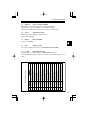
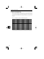
When communicating with a specific station, the tone squelch (CTCSS) function
can be used. Tone squelch is a function that enables you to receive a partner's
signal when the transmitted tone frequency matches your station's tone
frequency.
There are 38 different selectable tone number (frequencies)
26
No.
Frequency
1
67.0
No. Frequency
No. Frequency
No. Frequency
11
97.4
21
136.5
31
192.8
141.3
32
203.5
2
71.9
12
100.0
22
3
74.4
13
103.5
23
146.2
33
210.7
4
77.0
14
107.2
24
151.4
34
218.1
5
79.7
15
110.9
25
156.7
35
225.7
6
82.5
16
114.8
26
162.2
36
233.6
7
85.4
17
118.8
27
167.9
37
241.8
8
88.5
18
123.0
28
173.8
38
250.3
9
91.5
19
127.3
29
179.9
10
94.8
20
131.8
30
186.2
6. Selective Communicating
6-1 Tone Squelch
1. Press the FUNC key, then the ▲ key
while "F" icon appears.
"oF" icon blinks.
Press FUNC key then the ▲ key
again while "F" icon appears.
Blinking "oF" is replaced with a
blinking number (tone number :
default value is 08).
By repeating this process, the display
rotates as shown in the figure to the
right.
2. Change the Tone Number with ▲/
▼keys.
1-oF
1-08
1-oF
While the tone number is displayed,
press the ▲or▼key to select the
tone number to use from among the
tone list.
3. Press the PTT key or the V/M key to
complete the setting and return to the
normal mode.
Reference : During the setting operation, monitoring can be performed
by pressing the MONI key.
Caution : A high tone frequency setting could cause the squelch to open in
response to the characteristics of some voices. To decrease the
chances of this occurring, be sure to use the regular squelch
together with the tone squelch function.
27
7.Special Functions
7. Special Functions
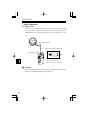
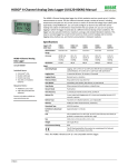
7-1 Theft Alarm
The transceiver has a theft alarm function that generates an alarm sound from
the speaker when a person not knowing the proper procedures removes the
unit.This function is useful when installing the unit in a remote place or in a
car.
Wiring Cable for Alarm
Steering Wheel
Alarm Cable Connection Illustration
Speaker Terminal Jack
Connect the center sleeve with
the ground (outer) sleeve.
There is no connection to the tip.
Caution
Cables A and B used with the alarm feature in our DR-135/235/435 products
cannot be used with this unit (the wiring is different).
28
7.Special Functions
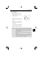
7-1-1 Connecting and Setting
1. Insert the plug of the alarm cable into the speaker terminal jack.
Caution • Position the alarm cable and transceiver firmly so that it will
not be easily detached.
• Program the CH-SC (for alarm) memory in advance to
cancel the alarm (page 12).
• Set CH-SC (for alarm) in the state where the squelch is
activated.
2. Select "SCr-on" in the Setting
mode.
"✻" appears on the display.
3. Turn OFF the power switch of the
transceiver.
Alarm setting will then turn ON.
4. To cancel the alarm setting, turn the
power ON, and select "SCr-oF" in
the Setting mode.
Caution • When setting the theft alarm function, connect the alarm cable
before turning the power OFF.
• The alarm may start sounding if the plug is inserted after
turning the power OFF.
29
7.Special Functions
7-1-2 Alarm
When the cable is pulled out or cut, the alarm will start sounding.
While alarming, all of the key operations are disabled including the power switch.
However, receiving is activated on the frequency recorded in the CH-SC (alarm
channel).
■ How to Stop the Alarm
When a signal is received and the squelch is unmuted during the alarm, the
alarm is canceled and the unit returns to the "receive" mode (A TSQ setting is
also a valid squelch setting).
It is possible to cancel the alarm using another transceiver from a remote place.
1. To cancel the alarm, detach the battery pack.
2. To set the alarm again, attach the battery pack and turn the power OFF.
Caution : Use the same battery pack that was in place when the alarm
function was activated (if an external power supply is used, the
alarm will continue sounding).
30
7.Special Functions
7-1-3 Alarm Delay
When this function is set, the alarm
starts sounding after an interval.
1. Set the alarm function to "SCr-dL"
in Setting mode "14".
2. Insert the plug of the alarm cable, and
turn the power of the transceiver
OFF.
In this setting, the alarm will not
sound until 10 seconds after the plug
is detached.
If the cable is detached during the
alarm setting procedure, the alarm
will start sounding 10 seconds later.
Caution • It is recommended that you use the tone squelch when setting
the CH-SC (for alarm), since there is the considerable
possibility that the alarm setting could be canceled by reception
of any random signal.
• Set the alarm function off (SCr-oF) during regular
operation.
• If the CH-SC (for alarm) memory is not programmed, you
can stop the alarm by sending a signal on the same frequency
appearing on the display, in the VFO mode.
31
8. Cloning
8. Cloning
8-1 Cloning
When using the cloning function, all setting information (including memory
data) of one transceiver (master unit) can be transferred and copied to another
transceiver (slave unit) by connecting them with a cable.
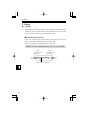
■ Connecting the Transceivers
Connect the external speaker jacks on both the master and slave transceivers
with a commercially available Ø3.5stereo mini plug cable.
After connecting them, switch the both units' power ON.
Caution : Connect the cable ONLY while the transceiver power is OFF.
Master
To SP jack on the
transceiver
Slave
To SP jack on the
transceiver
Ø3.5 stereo mini plug cable
32
8. Cloning
■Transmitting the Master
Data
1. Press and hold the MONI key and
press the PTT key three times.
"CLONE" appears on the display to
indicate the Clone mode is activated.
2. Press the PTT key.
"Sd ✻✻✻" is displayed and
internal setting information is
transferred into the "slave"
transceiver.
"PASS" appears when the cloning
completes.
The same data is transmitted by
pressing the PTT key while the
"PASS" is displayed.
Cloning Complete
If the data is not transmitted correctly,
"PASS" is not displayed. Repeat from
procedure 1.
3. To cancel the Clone mode, switch the
power off.
Caution : If the cable is not connected correctly, "CHECK" appears on
the display.
Check the cable connection again.
33
8. Cloning
■ Receiving the Master Data
1."Ld ✻✻✻" appears on the slave
transceiver's display while the master
data is transmitted.
"Ld 078" remains displayed when the
cloning is completed.
The receiving side cannot recognize
whether the data has been transmitted
correctly. Check to see if "PASS" is
displayed on the transmitting (master)
side.
2. Switch the transceiver power OFF.
Caution • Do not disconnect the cable while cloning.
• All data in the slave transceiver will be updated to the master
transceiver's data during the cloning operation. Be sure you
want to change everything before cloning.
34
9. Maintenance and Reference
9. Maintenance and Reference
9-1 Resetting
When you reset the transceiver, all settings are returned to the initial factory
(default) settings.
1. Turn the power ON while the FUNC key and V/M key are held down.
2. When all the display indications appear, release the FUNC key.
The transceiver enters the VFO mode.
The Initial Factory Settings
DJ-S446
VFO Frequency Number
1
CALL Frequency Number
1
Memory Channel 0~99
Tone Squelch Setting
Unset
...
Tone Number
8
Stand-by-beep Setting
ON
Key Lock Setting
OFF
Battery Saving
ON
Squelch Level Setting
07
35
9. Maintenance and Reference
9-2 Options
36
EBP-52N
Ni-MH Battery Pack (3.6V 500mAh)
EBP-53N
EBP-54N
Ni-MH Battery Pack (6.0V 500mAh)
Ni-MH Battery Pack (3.6V 1500mAh)
EDC-36
EDC-37
Cigarette Lighter Cable with Filter (DC12V)
DC Cable for Base Station (DC12V)
EDC-43
EDC-93
Cigar Lighter Cable for Recharging (DC12V)
Battery Charger (Wall Charger) 110V
EDC-94
EDC-105
Battery Charger (Wall Charger) 230V
Battery Charger (Trickle Charger)
EMS-9
EMS-51
Speaker Microphone
Speaker Microphone
EME-6
EME-12
EME-13
Earphone
Head Set with VOX (Headphone Type)
Head Set with VOX (Inner Type)
EME-15
EME-16
Tie Pin Microphone with VOX
Earphone Microphone
EME-17
EME-20
Earphone Microphone
Earphone Microphone
ESC-37
Softcase
10. Specifications
DJ-S446
10. Specifications
General
Frequency Range
446.00625~446.09375MHz (12.5kHz step 8CH)
Modulation
F3E (FM)
Tuning Steps
12.5kHz
Memory Channel
100 Channels + 1 Call Channel
Ant. Impedance
50 Ω
Frequency Stability
± 5ppm
Mic. Impedance
2k Ω
Supply Voltage
4.5 ~16.0VDC
Current
Transmit H
approx.370mA
L
approx.220mA
approx.150mA (Max)
Reception
approx.40mA (Squelched)
Battery Save :15mA
Operating temperature
-10 ~ +60˚C
Ground
Negative Grounding
Dimension
56 (W) ✕ 102 (H) ✕ 30 (D) mm
Weight
Approx. 95g (without Battery)
(EBP-53N Inclusive) (2.20" ✕ 4.01" ✕ 1.18")
Approx. 160g (EBP-53N Inclusive)
37
10. Specifications
Transmitter
Power Output
500mW
Approx.150mW LOW
Modulation
Variable Reactance
Spurious Emission
- 60dB or less
Max. Deviation
± 2.5kHz
Mic. Impedance
2k Ω
Receiver
System
Double-Conversion Super Heterodyne
Sensitivity
- 14.0dBu (0.2uV) or less
Intermediate Frequencies
1st IF : 21.7MHz
2nd IF : 450kHz
Selectivity
-6dB : 6kHz or over
-60dB : 14kHz or less
AF Output
280mW or over (MAX)
200mW or over (10% Distortion factor 8 Ω)
• Specifications may be changed without a preliminary announcement in
connection with technical development.
38
39
ALINCO, INC.
Head Office:
Phone:
E-mail:
Shin-Dai building 9th Floor
2-6, 1-Chome, Dojimahama, Kita-ku, Osaka 530-0004, JAPAN
+81-6-4797-2136 Fax: +81-6-4797-2157
[email protected]
Printed in Japan
Copyright Alinco, Inc, 2001 PS0396