1
CONTENTS
SERVICING INSTRUCTIONS
Technical Data
Page 3
Hob Touch Controls
Unpacking
Page 3
Operating Instructions
Page 11
Your Cooker
Page 4
Before Cooking
Page 15
Spacing & Dimensions/Extraction
Page 5
Cleaning
Page 15
Connecting the Cooker
Page 6
Servicing Instructions
Page 16
Ovens & Grill
Page 6
Wiring Diagram
Page 17
Induction Hob
Page 9
Page 9
Isolate the electrical supply before any repair work.
The cooker does not require regular servicing, but has been designed so that internal components are
easy to replace in the event that they become faulty.
It is preferable that access to internal parts is made by lifting off the hob.
All the oven and grill elements can be removed and replaced from the front of the cooker through the
oven openings.
To Remove the Base Element from the Bottom Oven
1. Remove the shelves and shelf supports from the oven.
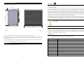
TECHNICAL DATA
ESSE, ENGLAND
INPUT
45A
2. Remove the two screws holding down the oven base at each side. Remove the base.
MODEL
ESSE, ELECTRIC
SERIAL No.
VOLTAGE
SUPPLY
- 250V
50 Hz a.c.
3. Undo the screw fastening the element to the side of the oven. The element can then be pulled out of
the base of the oven. The electrical wire connections should stay attached to the element as it is
pulled from the oven. The element wire terminals can then be swapped from the faulty element to the
new element. Take care not to let the element wire connections fall back inside the cooker before
they are reconnected to the new element.
To Remove the Upper Elements/Grill Element from the Top or Bottom Oven
The cooker Data Plate is located inside the right hand side lower oven door.
1. Undo the single screw fastening the element to the side of the oven.
2. Loosen the screws on the element support brackets. The support brackets can then be rotated clear
of the elements allowing the elements to fall.
UNPACKING
After unpacking the cooker, remove all the packing from the top and bottom ovens including protective
film on door liners. Examine the cooker for any damage, particularly to the hob glass.
3. The electrical wire connections should stay attached to the element as it is lowered. The element wire
terminals can then be swapped from the faulty element to the new one. Take care not to let the
element wire connections fall back inside the cooker before they are reconnected to the new
element.
If there is any damage to the cooker or anything is missing, please contact your supplier for advice.
To Remove the Fan Unit from the Main Oven
If the hob is cracked the cooker must not be connected, and no part of it may be used.
Unscrew the six screws around the unit, pull the unit out with the wires attached, being careful not to
allow them to fall back into the oven. Remove the fan guard by unscrewing the fixing screws on the top
and two on the bottom of the unit.
To Remove the Induction Elements
Lift off the top.
Unbolt the 6 bolts holding the Induction support panel carefully. Each Induction coil will lift out.
To Replace the Element
Undo the 3 screws holding it, insert new element and replace wires.
To Replace the Motor
Unscrew the fan blade nut, unbolt the 3 fixing bolts, replace motor ensuring the spacing nuts and
wires are correct!
2
15