1
User’s Manual
The Printronix SL5000e and T5000e
Series of Thermal Printers
™
™
Software License Agreement
CAREFULLY READ THE FOLLOWING TERMS AND CONDITIONS
BEFORE USING THIS PRINTER. USING THIS PRINTER INDICATES
YOUR ACCEPTANCE OF THESE TERMS AND CONDITIONS. IF YOU DO
NOT AGREE TO THESE TERMS AND CONDITIONS, PROMPTLY RETURN
THE PRINTER AND ALL ACCOMPANYING HARDWARE AND WRITTEN
MATERIALS TO THE PLACE YOU OBTAINED THEM, AND YOUR MONEY
WILL BE REFUNDED.
Definitions
“Software” shall mean the digitally encoded, machine-readable data and
program. The term “Software Product” includes the Software resident in the
printer and its documentation. The Software Product is licensed (not sold) to
you, and Printronix, Inc. either owns or licenses from other vendors who own
all copyright, trade secret, patent and other proprietary rights in the Software
Product.
License
1. Authorized Use. You agree to accept a non-exclusive license to use the
Software resident in the printer solely for your own customary business or
personal purposes.
2. Restrictions.
a. To protect the proprietary rights of Printronix, Inc., you agree to
maintain the Software Product and other proprietary information
concerning the typefaces in strict confidence.
b. You agree not to duplicate or copy the Software Product.
c.
You shall not sublicense, sell, lease, or otherwise transfer all or any
portion of the Software Product separate from the printer, without the
prior written consent of Printronix, Inc.
d. You may not modify or prepare derivative works of the Software
Product.
e. You may not transmit the Software Product over a network, by
telephone, or electronically using any means; or reverse engineer,
decompile or disassemble the Software.
f.
You agree to keep confidential and use your best efforts to prevent
and protect the contents of the Software Product from unauthorized
disclosure or use.
3. Transfer. You may transfer the Software Product with the printer, but only
if the recipient agrees to accept the terms and conditions of this
Agreement. Your license is automatically terminated if you transfer the
Software Product and printer.
Limited Software Product Warranty
Printronix, Inc. warrants that for ninety (90) days after delivery, the Software
will perform in accordance with specifications published by Printronix, Inc.
Printronix, Inc. does not warrant that the Software is free from all bugs, errors
and omissions.
Remedy
Your exclusive remedy and the sole liability of Printronix, Inc. in connection
with the Software is replacement of defective software with a copy of the
same version and revision level.
Disclaimer of Warranties and Limitation of Remedies
1. THE PARTIES AGREE THAT ALL OTHER WARRANTIES, EXPRESS
OR IMPLIED, INCLUDING WARRANTIES OF FITNESS FOR A
PARTICULAR PURPOSE AND MERCHANTABILITY ARE EXCLUDED.
Printronix, Inc. does not warrant that the functions contained in the
Software will meet your requirements or that the operation of the Software
will be uninterrupted or error free. Printronix, Inc. reserves the right to
make changes and/or improvements in the Software without notice at any
time.
2. IN NO EVENT WILL PRINTRONIX, INC. BE LIABLE FOR LOST
PROFITS, LOST DATA, BUSINESS INTERRUPTIONS, OR ANY
OTHER DIRECT, INDIRECT, INCIDENTAL OR CONSEQUENTIAL
DAMAGES ARISING OUT OF THE USE OF OR INABILITY TO USE
THIS PRODUCT, EVEN IF PRINTRONIX, INC. HAS BEEN ADVISED OF
THE POSSIBILITY OF SUCH DAMAGES, OR ANY DAMAGES CAUSED
BY THE ABUSE OR MANIPULATION OF THE SOFTWARE. SOME
STATES DO NOT ALLOW THE EXCLUSION OR LIMITATION OF
LIABILITY FOR CONSEQUENTIAL OR INCIDENTAL DAMAGES, SO
THE ABOVE LIMITATION MAY NOT APPLY TO YOU.
3. Printronix, Inc. will not be liable for any loss or damage caused by delay in
furnishing a Software Product or any other performance under this
Agreement.
4. Our entire liability and your exclusive remedies for our liability of any kind
(including liability for negligence except liability for personal injury caused
solely by our negligence) for the Software Product covered by this
Agreement and all other performance or nonperformance by us under or
related to this Agreement are limited to the remedies specified by this
Agreement.
5. California law governs this Agreement.
Termination of License Agreement
This License shall continue until terminated. This license may be terminated
by agreement between you and Printronix, Inc. or by Printronix, Inc. If you fail
to comply with the terms of this License and such failure is not corrected
within thirty (30) days after notice. When this License is terminated, you shall
return to the place you obtained them, the printer and all copies of the
Software and documentation.
U.S. Government Restricted Rights
Use, duplication or disclosure by the government is subject to restrictions as
set forth in the Rights in Technical Data and Computer Software clause at
FAR 242.227-7013, subdivision (b) (3) (ii) or subparagraph (c) (1) (ii), as
appropriate. Further use, duplication or disclosure is subject to restrictions
applicable to restricted rights software as set forth in FAR 52.227-19 (c) (2).
Acknowledgement of Terms and Conditions
YOU ACKNOWLEDGE THAT YOU HAVE READ THIS AGREEMENT,
UNDERSTAND IT, AND AGREE TO BE BOUND BY ITS TERMS AND
CONDITIONS. NEITHER PARTY SHALL BE BOUND BY ANY STATEMENT
OR REPRESENTATION NOT CONTAINED IN THIS AGREEMENT. NO
CHANGE IN THIS AGREEMENT IS EFFECTIVE UNLESS WRITTEN AND
SIGNED BY PROPERLY AUTHORIZED REPRESENTATIVES OF EACH
PARTY. BY USING THIS PRINTER, YOU AGREE TO ACCEPT THE TERMS
AND CONDITIONS OF THIS AGREEMENT.
Communication Notices
T5000e
Federal Communications Commission (FCC) Statement: This equipment
has been tested and found to comply with the limits for a Class A digital
device, pursuant to Part 15 of the FCC Rules. These limits are designed to
provided reasonable protection against harmful interference when the
equipment is operated in a commercial environment. This equipment
generates, uses, and can radiate radio frequency energy and, if not installed
and used in accordance with the instruction manual, may cause harmful
interference to radio communications. Operation of this equipment in a
residential area is likely to cause harmful interference, in which case the user
will be required to correct the interference at his own expense.
Properly shielded and grounded cables and connectors must be used in order
to meet FCC emission limits. Printronix is not responsible for any radio or
television interference caused by using other than recommended cables and
connectors or by any unauthorized changes or modifications to this
equipment. Unauthorized changes or modifications could void the user’s
authority to operate the equipment.
This device complies with Part 15 of the FCC Rules. Operation is subject to
the following two conditions: (1) this device may not cause harmful
interference, and (2) this device must accept any interference received,
including interference that may cause undesired operation.
Canadian Department of Communications Compliance Statement: This
Class A digital apparatus complies with Canadian ICES-003.
Avis de conformite aux normes du ministere des Communcations du
Canada: Cet appareil numerique de la classe A est conform á norme NMB003 du Canada.
European Community (EC) Conformity Statement:
This product is in conformity with the protection requirements of EC Council
Directive 89/336/EEC on the approximation of the laws of the Member States
relating to electromagnetic compatibility. Printronix cannot accept
responsibility for any failure to satisfy the protection requirements resulting
from a non-recommended modification of the product, including the fitting of
non-Printronix option cards.
German Conformity Statement:
Zulassungsbescheinigung Gesetz über die elektromagnetische
Verträglichkeit von Geraten (EMVG) vom 30. August 1995
Dieses Gerät ist berechtigt in Übereinstimmung mit dem deutschen das EGKonformitätszelchen - CE - zu führen.
Der Außteller der Konformitätserklärung ist die Printronix......(1)
Informationen in Hinsicht EMVG Paragraph 3 Abs. (2) 2:
Das Gerät erfüllt die Schutzanforderungen nach EN 55024 und
EN 55022 Klasse A.
EN 55022 Klasse A Geräte bedürfen folgender Hinweise:
Nach dem EMVG: “Geräte dürfen an Orten, für die sie nicht asreichend
entstört sind, nur mit besonderer Genehmigung des Bundesminesters für
Post und Telekommunikation oder des Bundesamtes für Post und
Telekommunikation betrieben werden. Die Genehmigung wird erteilt, wenn
keine elektromagnetischen Störungen zu erwarten sind.” (Auszug aus dem
EMVG, Paragraph 3, Abs. 4) Dieses Genehmigungsverfahren ist nach
Paragraph 9 EMVG in Verbindung mit der entsprechenden Kostenverordnung
(Amtsblatt 14/93) kostenpflichtig.
EN 55022: Dieses ist eine Kategorie A Vorrichtung. Betrieb in den
Wohnbereichen kann elektrische Störung verursachen. Es ist die
Verantwortlichkeit des Benutzers, passende Gegenmaßnahmen zu ergreifen.
EN 55024: Begrenzung Werte für Gebrauch in bevölkerten Bereiche,
kommerziellen und Industriegebieten sind innen Übereinstimmung mit den
spezifizierten Anforderungen Hinsichtlich Störfreiheit.
Anmerkung: Um die Einhaltung des EMVG sicherzustellen sind die Geräte,
wie in den Handbüchern angegeben, zu installieren und zu betreiben.
This product has been tested and found to comply with the limits for Class A
Information Technology Equipment according to European Standard EN
55022. The limits for Class A equipment were derived for commercial and
industrial environments to provide reasonable protection against interference
with licensed communication equipment.
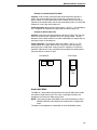
Warning
This is a Class A product. In a domestic
environment this product may cause radio
interference in which case the user may be
required to take adequate measures.
SL5000e
Hereby, Printronix, Inc., declares that this T5204e, T5304e, SL5204e,
SL5304e with optional suffixes is in compliance with the essential
requirements and other relevant provisions of Directive 1999/5/EC.
Par la présente Printronix, Inc. déclare que l'appareil T5204e, T5304e,
SL5204e, SL5304e avec des suffixes facultatifs est conforme aux exigences
essentielles et aux autres dispositions pertinentes de la directive 1999/5/CE.
Par la présente, Printronix, Inc. déclare que ce T5204e, T5304e, SL5204e,
SL5304e avec des suffixes facultatifs est conforme aux exigences
essentielles et aux autres dispositions de la directive 1999/5/CE qui lui sont
applicables.
Hiermit erklärt Printronix, Inc., dass sich dieser/diese/dieses T5204e, T5304e,
SL5204e, SL5304e mit wahlweise freigestellten Suffixen in Übereinstimmung
mit den grundlegenden Anforderungen und den anderen relevanten
Vorschriften der Richtlinie 1999/5/EG befindet. (BMWi)
Con la presente Printronix, Inc. dichiara che questo T5204e, T5304e,
SL5204e, SL5304e con i suffissi facoltativi è conforme ai requisiti essenziali
ed alle altre disposizioni pertinenti stabilite dalla direttiva 1999/5/CE.
Por medio de la presente Printronix, Inc. declara que el T5204e, T5304e,
SL5204e, SL5304e con sufijos opcionales cumple con los requisitos
esenciales y cualesquiera otras disposiciones aplicables o exigibles de la
Directiva 1999/5/CE.
This equipment has been tested and found to comply with the limits for a
Class B digital device, pursuant to Part 15 of the FCC Rules. These limits are
designed to provide reasonable protection against harmful interference in a
residential installation. This equipment generates, uses, and can radiate radio
frequency energy and, if not installed and used in accordance with the
instructions, may cause harmful interference to radio communications.
However, there is no guarantee that interference will not occur in a particular
installation. If this equipment does cause harmful interference to radio or
television reception, which can be determined by turning the equipment off
and on, the user is encouraged to try to correct the interference by one or
more of the following measures:
•
•
•
Reorient or relocate the receiving antenna.
•
Consult the dealer or an experienced radio/TV technician for help.
Increase the separation between the equipment and receiver.
Connect the equipment into an outlet on a circuit different from that to
which the receiver is connected.
Properly shielded and grounded cables and connectors must be used in order
to meet FCC emission limits. Printronix is not responsible for any radio or
television interference caused by using other than recommended cables and
connectors or by any unauthorized changes or modifications to this
equipment. Unauthorized changes or modifications could void the user’s
authority to operate the equipment.
This device complies with part 15 of the FCC Rules. Operation is subject to
the following two conditions: (1) this device may not cause harmful
interference, and (2) this device must accept any interference received,
including interference that may cause undesired operation.
Any change or modification to this product voids the user’s authority to
operate it per FCC Part 15 Subpart A Section 15.21 regulations.
CAUTION: This product should be positioned so that personnel in the area for
prolonged periods may safely remain at least 23 cm (9 in) from the readers
antenna surface in an uncontrolled environment. See FCC OET Bulletin 56
“Hazards of radio frequency and electromagnetic fields.”
This product contains an intentional radiator with the following parameters:
Operating Frequency: 902 to 928 MHz
Typical RF Power: 25 to 100 milliwatts (SL5x04 MP) or 25 to 205 milliwatts
(SL5x04 C1)
Maximum RF Power: 1 Watt under abnormal conditions
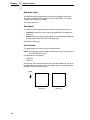
Printronix SL5000e and T5000e SR
Tested To Comply
With FCC Standards
FOR HOME OR OFFICE USE
Canada
This Class B digital apparatus complies with Canadian ICES-003 and
RSS 210.
Cet appareil numérique de la classe B est conforme à la norme NMB-003
du Canada.
CE Notice (European Union)
Marking by the CE symbol indicates compliance of this Printronix system to
the EMC Directive and the Low Voltage Directive of the European Union.
Such marking is indicative that this Printronix system meets the following
technical standards:
•
EN 300 220-1 (2000), Electromagnetic Compatibility and Radio Spectrum
Matters; Short Range Devices; Radio equipment to be used in the 25
MHz 10 1000 MHz frequency range with power levels ranging up to 500
mW.
•
EN 55022 — “Limits and Methods of Measurement of Radio Interference
Characteristics of Information Technology Equipment.”
•
EN 50082-1: 1992 — “Electromagnetic compatibility—Generic immunity
standard Part 1: Residential, commercial, and light industry.”
•
EN 60950 — “Safety of Information Technology Equipment.”
This printer is a Class B product for use in a typical Class B domestic
environment.
CE Symbol
Declaration Of Conformity
Manufacturer:
Printronix, Inc.
14600 Myford Rd.
Irvine, CA 92623 U.S.A.
declares that the product:
Product Type:
Information Technology Equipment, Printer
Equipment Class:
Commercial and Light Industrial
Model Numbers:
T5204e, T5304e, SL5204e, SL5304e with
optional suffixes
Configuration:
serial, parallel, coax, twinax, external LAN,
Ethernet, Wireless Ethernet, RFID
conforms to the following standards:
Safety:
EN 60950: 1992 +A1, A2, A3, A4, A11
EMC:
ETSI EN 301 489-1
ETSI EN 301 489-3
ETSI EN300 220 V1.3.1 Sec. 8.1, 8.2, 8.6, 8.7, 8.9
EN 55022: 1998 +A1 Class B
EN 55024: 1998
EN 61000-4-2
EN 61000-4-3
EN 61000-4-4
EN 61000-4-5
EN 61000-4-6
EN 61000-4-8
EN 61000-4-11
EN 61000-3-2: 2000
EN 61000-3-3: 1995 +A1
and complies with:
The Low Voltage Directive 73/23/EEC and the EMC Directive 89/336/EEC.
Taiwan
Lithium Battery Warning
The controller board contains a lithium battery sealed inside the real-time
clock chip. Do not disassemble the chip to replace the battery. Do not dispose
of the chip by incineration. Failure to comply may cause the battery to
explode. Contact your local waste agency for the correct disposal procedure.
Printronix makes no representations or warranties of any kind regarding this
material, including, but not limited to, implied warranties of merchantability
and fitness for a particular purpose. Printronix shall not be held responsible
for errors contained herein or any omissions from this material or for any
damages, whether direct, indirect, incidental or consequential, in connection
with the furnishing, distribution, performance or use of this material. The
information in this manual is subject to change without notice.
This document contains proprietary information protected by copyright. No
part of this document may be reproduced, copied, translated or incorporated
in any other material in any form or by any means, whether manual, graphic,
electronic, mechanical or otherwise, without the prior written consent of
Printronix.
Copyright 2002, 2005, Printronix, Inc.
Trademark Acknowledgements
Printronix, IGP, IGP/Auto Label Mapping, LinePrinter Plus, PGL, and PrintNet
are registered trademarks of Printronix, Inc.
ThermaLine, T5000e, and SL5000e is a trademark of Printronix.
HP is a registered trademark of Hewlett-Packard Company.
PCL is a registered trademark of Hewlett-Packard Company.
Code V is a trademark of QMS, Inc.
QMS is a registered trademark of Quality Micro Systems, Inc.
IBM is registered trademark of International Business Machines Corp.
MS-DOS and Windows are registered trademarks of Microsoft Corporation.
Centronics is a registered trademark of Genicom Corporation.
IEEE is a registered service mark of the Institute of Electrical and Electronic
Engineers, Inc.
ANSI is a registered trademark of American National Standards Institute, Inc.
EIA is a registered service mark of Electronic Industries Association.
IMPORTANT WARRANTY INFORMATION
PRINTER WARRANTY
Printronix® warrants to purchaser that under normal use and service, this
printer (excluding the thermal printhead) purchased hereunder shall be free
from defects in material and workmanship for a period of ninety (90) days
from the date of shipment from Printronix.
Consumable items such as media and ribbons are not covered under this
warranty. This warranty does not cover equipment or parts that have been
misused, altered, or used for purposes other than those for which they were
manufactured. This warranty also does not cover loss, shipping damage,
damage resulting from accident or damages resulting from unauthorized
service.
THERMAL PRINTHEAD
Printronix warrants the printhead for a period of one hundred eighty (180)
days, or 1,000,000 linear inches for direct thermal use, or 2,000,000 linear
inches for thermal transfer use, whichever comes first. The warranty does not
cover printheads that have been misused, damaged due to improper
cleaning, or damaged due to use of improper ribbons or media.
SUPPLIES
For the nearest Printronix full-service distributor that carries Printronix
genuine supplies, please call 1-800-733-1900 or fax (714)-368-2354.
Supplies design, specification, and selection are integral to the development
of any computer imaging system. Printronix's extensive manufacturing and
research capabilities, along with years of experience in the design of printers
and their applications, assures that you will receive the exact materials that
you require to maximize the performance of your Printronix printer. For more
information, call the Printronix Customer Solutions Center at (714) 368-2686
or access the Printronix website at http://www.printronix.com.
ON-SITE MAINTENANCE SERVICE
Printronix offers on-site support services in the United States. Please contact
the Printronix Maintenance Contracts Group at (714) 368-2798 for detailed
service agreement information.
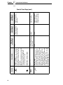
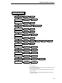
Table of Contents
1 Introduction ......................................................... 21
Printronix Customer Support Center.................................................... 21
Training Available On Printronix Products ........................................... 21
Warnings And Special Information ...................................................... 22
Manual Conventions ............................................................................ 22
The T5000 Series Label Printer........................................................... 23
Standard Features ........................................................................ 24
Optional Features.......................................................................... 25
Thermal Printer Technology ................................................................ 27
The Printing Process ..................................................................... 27
Dynamic Print Control ................................................................... 27
Thermal Consumables......................................................................... 28
Media Selection............................................................................. 28
Ribbons ......................................................................................... 28
Setting Up The Printer ......................................................................... 29
Unpacking The Printer .................................................................. 29
Installation ..................................................................................... 31
2 Operation ............................................................ 35
Controls And Indicators ....................................................................... 35
Power Switch ................................................................................ 35
Control Panel ................................................................................ 35
Powering On The Printer............................................................... 39
Operating Modes........................................................................... 39
Media Handling Modes ........................................................................ 39
Loading Media And Ribbon ................................................................. 40
Loading Roll Media ....................................................................... 41
Loading Fanfold Media.................................................................. 48
Loading Ribbon ............................................................................. 53
Using The Optional Internal Rewinder................................................. 56
Batch Rewind Mode ...................................................................... 56
Label Peel-Off ............................................................................... 62
Removing The Media Guide.......................................................... 65
Table of Contents
Printing Adjustments............................................................................ 66
Printhead Pressure Adjustment .................................................... 66
Printhead Pressure Block Adjustments ......................................... 67
Positioning The Media Sensors .................................................... 68
Sensing Different Media Types ..................................................... 73
Running Auto Calibrate ................................................................. 74
Running Media Profile................................................................... 75
Running Manual Calibrate............................................................. 77
Cleaning............................................................................................... 78
General Cleaning .......................................................................... 78
Printhead Cleaning........................................................................ 78
3 Configuring The Printer ....................................... 81
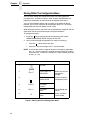
Overview.............................................................................................. 81
Setting Printer Configuration Parameters ..................................... 81
Moving Within The Configuration Menu ........................................ 82
Selecting A Menu Option .............................................................. 83
Changing Printer Settings ............................................................. 83
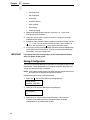
Saving A Configuration ................................................................. 84
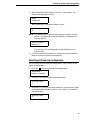
Specifying A Power-Up Configuration ........................................... 85
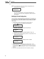
Modifying A Saved Configuration .................................................. 86
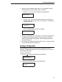
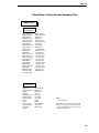
Printing A Configuration ................................................................ 87
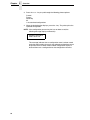
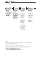
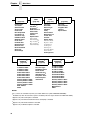
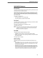
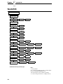
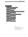
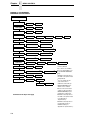
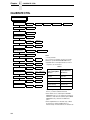
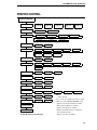
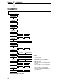
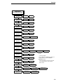
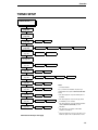
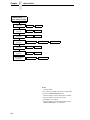
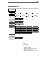
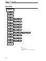
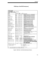
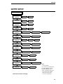
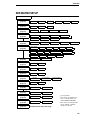
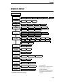
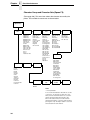
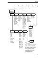
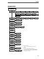
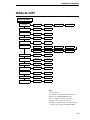
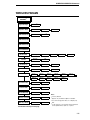
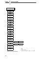
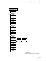
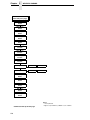
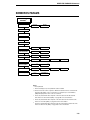
Menu Overview.................................................................................... 91
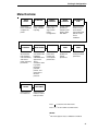
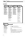
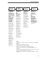
Main Menu ........................................................................................... 92
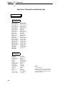
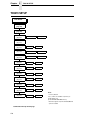
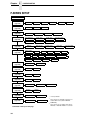
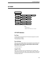
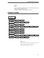
QUICK SETUP .................................................................................. 100
QUICK SETUP Submenus.......................................................... 101
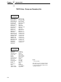
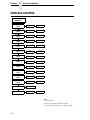
VALIDATOR ...................................................................................... 108
VALIDATOR Submenus.............................................................. 110
CONFIG. CONTROL ......................................................................... 115
CONFIG. CONTROL Submenus ................................................ 116
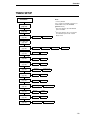
MEDIA CONTROL............................................................................. 118
MEDIA CONTROL Submenus .................................................... 120
CALIBRATE CTRL ............................................................................ 134
CALIBRATE CTRL Submenus.................................................... 135
PRINTER CONTROL ........................................................................ 141
PRINTER CONTROL Submenus................................................ 144
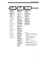
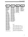
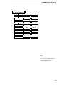
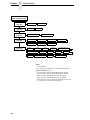
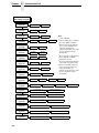
EMULATIONS ................................................................................... 154
Overview ..................................................................................... 154
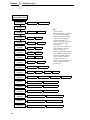
COAX SETUP.................................................................................... 158
TWINAX SETUP................................................................................ 161
SPC COAX SETUP ........................................................................... 164
SPC TWINAX SETUP ....................................................................... 165
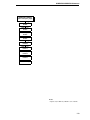
Table of Contents
IPDS SETUP ..................................................................................... 166
TN3270 SETUP ................................................................................. 170
TN5250 SETUP ................................................................................. 173
IGP/PGL SETUP ............................................................................... 175
IGP/VGL SETUP ............................................................................... 178
IGP/PPI1 SETUP............................................................................... 181
IGP/PPI2 SETUP............................................................................... 183
P-SERIES SETUP ............................................................................. 184
P-SER XQ SETUP............................................................................. 187
SER MATRIX SETUP........................................................................ 189
PROPRINTER SETUP ...................................................................... 191
EPSON FX SETUP............................................................................ 193
Emulation Submenus......................................................................... 195
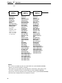
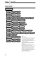
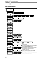
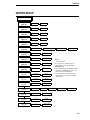
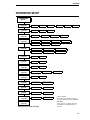
DIAGNOSTICS .................................................................................. 249
DIAGNOSTICS Submenus ......................................................... 250
PARALLEL PORT.............................................................................. 253
PARALLEL PORT Submenus ..................................................... 254
SERIAL PORT ................................................................................... 257
SERIAL PORT Submenus .......................................................... 258
C/T PORT .......................................................................................... 265
C/T PORT Submenus ................................................................. 265
ETHERNET ADDRESS ..................................................................... 267
ETHERNET ADDRESS Submenus ............................................ 268
ETHERNET PARAMS ....................................................................... 269
ETHERNET PARAMS Submenus............................................... 270
WIRELESS ADDRESS...................................................................... 272
WIRELESS ADDRESS Submenus ............................................. 273
WIRELESS PARAMS ........................................................................ 275
WIRELESS PARAMS Submenus ............................................... 280
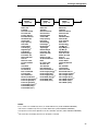
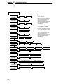
KERBEROS PARAMS....................................................................... 283
KERBEROS PARAMS Submenus .............................................. 284
BATTERY CONTROL........................................................................ 286
BATTERY CONTROL Submenus ............................................... 287
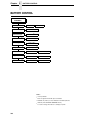
Downloading Emulation And Operating System Software................. 289
Flash Memory ............................................................................. 289
Downloading Software Through The Serial Or Parallel Port ....... 290
Downloading Software Through The
Network Interface Card (NIC)...................................................... 293
Downloading Optional Font Files To Flash Memory ................... 295
Downloading True Type Fonts .................................................... 298
Table of Contents
4 Interfaces .......................................................... 299
Overview............................................................................................ 299
Auto Switching ................................................................................... 299
Centronics Parallel Interface.............................................................. 300
Centronics Parallel Interface Signals .......................................... 301
IEEE 1284 Parallel Interface.............................................................. 302
Compatibility Mode...................................................................... 302
Nibble Mode ................................................................................ 302
Byte Mode ................................................................................... 302
Signals ........................................................................................ 303
Terminating Resistor Configurations ........................................... 305
RS-232 And RS-422 Serial Interfaces ............................................... 305
RS-232 ........................................................................................ 306
RS-422 ........................................................................................ 306
5 Diagnostics And Troubleshooting ..................... 307
Printer Tests ...................................................................................... 307
Troubleshooting Common Situations................................................. 307
Improving Processing Time......................................................... 308
Data Exchange............................................................................ 308
Controlling Print Quality .............................................................. 310
Determining Printhead Wear ....................................................... 311
Replacing The Printhead ................................................................... 312
Restore The Printer To Operation ..................................................... 314
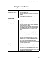
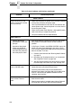
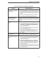
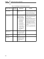
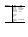
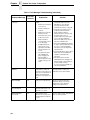
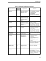
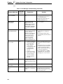
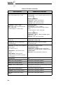
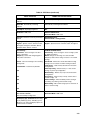
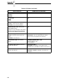
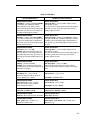
Solving Other Printer Problems................................................... 315
Printer Alarms ............................................................................. 322
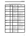
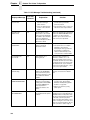
Fault Messages ........................................................................... 322
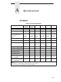
A Specifications .................................................... 337
Print Method................................................................................ 337
Media .......................................................................................... 338
Ribbon ......................................................................................... 340
Indicators And Switches .............................................................. 340
Memory ....................................................................................... 340
Media Cutter Options .................................................................. 341
Host Interfaces ............................................................................ 342
Power .......................................................................................... 342
Environmental ............................................................................. 343
Physical ....................................................................................... 343
Acoustic Specifications ............................................................... 343
Maximum Page Length ............................................................... 344
Table of Contents
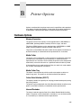
B Printer Options .................................................. 345
Hardware Options.............................................................................. 345
Interface Options ......................................................................... 346
Supplies And Accessories ................................................................. 347
Genuine Printronix Thermal Transfer Ribbons............................ 348
Genuine Printronix Media............................................................ 349
Accessories ................................................................................. 351
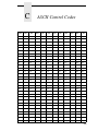
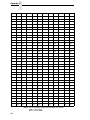
C ASCII Control Codes......................................... 353
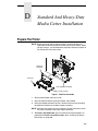
D Standard And Heavy-Duty Media Cutter
Installation......................................................... 355
Prepare The Printer ........................................................................... 355
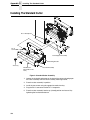
Installing The Standard Cutter ........................................................... 356
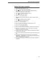
Restore The Printer To Operation ............................................... 357
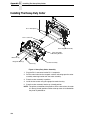
Installing The Heavy-Duty Cutter....................................................... 358
Restore The Printer To Operation ............................................... 359
Removing The Media Cutter.............................................................. 360
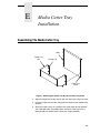
E Media Cutter Tray Installation ........................... 361
Assembling The Media Cutter Tray ................................................... 361
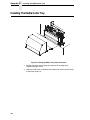
Installing The Media Cutter Tray........................................................ 362
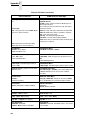
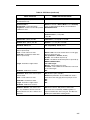
F PPI1 and PPI2 Menu Conversions ................... 365
G Glossary............................................................ 375
Table of Contents
1
Introduction
Printronix Customer Support Center
The Printronix Customer Support Center offers technical support with:
•
•
•
•
•
Installation
Configuration and setup
Operation and supplies loading
Specifications of the proper print media and ribbon
Answers to post-sale service support questions
Call the Printronix Customer Support Center at:
1-714-368-2686 in the Americas
31-24-6489489 in Europe, Middle East, and Africa
65-65484114 in Asia Pacific
or visit the Printronix web page at www.printronix.com
http://www.printronix.com/public/servicesupport/default.aspx
Training Available On Printronix Products
Printronix offers Product Maintenance Training Classes designed to enhance
the knowledge of your service personnel. Led by Printronix’ staff of highly
trained, experienced instructors, these structured classes include:
•
•
•
•
Hands-on work with the product
Theory of operation
Diagnosis of equipment failures
Preventive and corrective maintenance requirements and procedures.
Customized classes designed to meet your specific needs are available upon
request. Call Customer Training at (714) 368-2332 or visit the Printronix
website at www.printronix.com.
21
Chapter
1
Warnings And Special Information
Warnings And Special Information
For your safety and to protect valuable equipment, read and comply with all
information highlighted under special headings:
WARNING
Conditions that could harm you and damage the equipment.
WARNING
Achten Sie auf folgendes, um keine Personen in Gefahr zu bringen bzw.
das Gerät zu beschädigen.
WARNING
Condiciones que pueden causar daños a personas y equipos.
WARNING
Conditions à respecter pour éviter tout danger corporel et dommage
matériel.
WARNING
Condizioni che possono arrecare danni alle persone e alle
apparecchiature.
CAUTION
IMPORTANT
Conditions that could damage the printer or related equipment.
Information vital to proper operation of the printer.
NOTE: Information and helpful tips about printer operation.
Manual Conventions
•
Operator panel keys are printed in uppercase letters.
Example: Press the PAUSE key and then press ENTER.
•
Operator panel keys are often shown by their symbol or icon (located on
the control panel directly below the key).
Example: Press the ↵ key for ENTER.
•
Liquid Crystal Display (LCD) messages are printed in uppercase letters
inside quotation marks ( “ ” ).
Example: When “OFFLINE” appears on the LCD, you may release the
PAUSE key.
•
LCD fault messages display the specific fault in uppercase letters on the
top line. A corrective action in upper and lowercase letters displays on the
bottom line.
Example: PAPER OUT
Load Paper
•
Key combinations are indicated by the + (plus) symbol.
Example: Press ↑ + ↓ means Press the Up ↑ key and the Down ↓ key at
the same time.
22
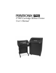
The T5000 Series Label Printer
NOTE: As used in this manual, the terms “T5000” and “printer” refer to all
models within the T5000 series. “SR” refers to all models that are
Smart Ready. “SL” refers to all SmartLine models.
The T5000 series consists of a family of high quality, direct thermal and
thermal transfer printers specifically designed for printing labels and tags from
any MS-DOS®, Windows®, ASCII, or EBCDIC (with the Coax/Twinax option)
based compatible computer.
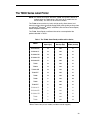
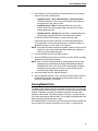
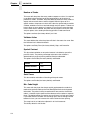
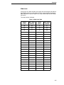
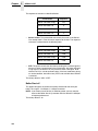
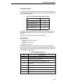
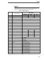
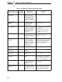
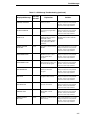
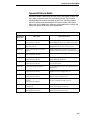
The T5000, Smart Ready, and SmartLine series are comprised of the
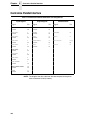
products detailed in Table 1.
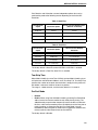
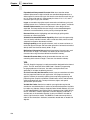
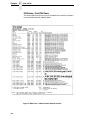
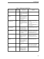
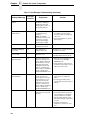
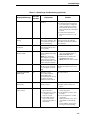
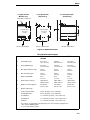
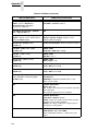
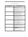
Table 1. The T5000, Smart Ready, and SmartLine Series
Model
Max Print
Speed (ips)
Printing
Density (dpi)
Max Print
Width (inches)
SL5204e-MP
10
203
4.1
SL5204e-C1
10
203
4.1
SL5204e-DK
10
203
4.1
SL5204e-SR
10
203
4.1
SL5304e-MP
8
300
4.1
T5204
10
203
4.1
T5204e
10
203
4.1
T5204e SR
10
203
4.1
T5204-DT*
10
203
4.1
T5206
10
203
6.6
T5208
8
203
8.5
T5304
8
300
4.1
T5304-DT*
8
300
4.1
SL5304e-C1
8
300
4.1
SL5304e-MP
8
300
4.1
SL5304e-SR
8
300
4.1
T5306
8
300
6.6
T5308
6
300
8.5
* Direct Thermal only 4 inch models (no ribbon transfer support)
23
Chapter
1
The T5000 Series Label Printer
Standard Features
•
Your thermal printer has the standard LinePrinter Plus® (LP+) emulation
which provides direct compatibility with Printronix P-series printers. In
addition, the printer has co-resident IGP®/PGL® and IGP/VGL emulations
which provide printer system commands for text, barcodes, graphics,
lines, and boxes.
•
Direct thermal printing and thermal transfer (thermal transfer is not
supported on 4 inch DT models).
•
Standard interfaces:
•
Serial: RS-232 and RS-422
•
Parallel: Centronics®-compatible parallel, IEEE® 1284 compliant
parallel
NOTE: The interface cable needed to connect the printer to the host device is
supplied by the user.
•
•
Supports over 20 types of bar codes.
Download fonts, forms, and graphics to printer memory.
The standard resident fonts are Letter Gothic Bold (#93779), Courier Bold
(#93952), CG Triumvirate Bold Condensed (#92250), OCR-A (#90993),
and OCR-B (#91409). All other fonts are optional.
24
•
•
High resolution printhead for sharp graphics and text.
•
Tear-Off mode for positioning the label at the tear-off position and
detecting its removal before printing the next label.
•
Tear-Off Strip mode for printing a specified number of labels and
positioning the last label at the tear-off position.
•
•
•
8MB DRAM memory.
•
Ventless system for operation in environments with airborne particulate
matter without compromising performance.
Label Taken Sensor for detecting removal of labels in Tear-Off mode (and
in Peel-Off mode when optional rewinder is installed).
4MB Flash memory.
Auto Label Mapping® for compatibility with programs written for Printronix
Line Matrix printers.
Optional Features
Optional Features
Ask your authorized representative about the following enhancement options:
•
Fonts: A selection of fonts is available to extend the capabilities of the
standard resident fonts.
•
Internal Label Rewinder: In label peel-off mode, peels off labels one at a
time before printing the next label and rewinds the liner into a discardable
roll. In batch rewind mode, rewinds printed labels into a removable roll.
•
Memory Expansion (for non-IPDS printers only):
•
16MB DRAM SIMM - Provides additional memory to accommodate
long label formats.
•
10MB Flash SIMM - Provides additional memory for forms, logos, and
fonts.
•
Media Cutter: The cutter is used to automatically cut printed media when
the media exits the printer. Cutters are available in the Standard 4 inch
model and the Heavy Duty 4 , 6, and 8 inch models. See Appendix A for
details.
•
Media Cutter Tray: This option is used with the media cutter option to
catch the cut media in a bin.
•
Coax/Twinax Host Interface: This provides connection to a host
computer system using a Coax or Twinax interface.
•
Network Interface Card (NIC): This option allows you to attach the
printer to a LAN (Local Area Network) rather than attaching it directly to a
host computer.
•
NIC adapters are available as an internally installed option, mounted
inside the printer with the 10/100Base-T (UTP) connection only. The
parallel port is no longer accessible when the NIC option is installed.
NOTE: In this manual, the terms “Network Interface Card” (or “NIC”) and
“Ethernet” are used interchangeably.
•
IPDS: IPDS™ is available for Twinax or a NIC or a combination of both.
NOTE: The basic NIC does not support IPDS.
•
TN5250/TN3270: The TN5250/TN3270 feature enables your printer to
communicate with an IBM host through a NIC using the 5250/3270
datastream. This feature allows you to use an application generated for
the Twinax/Coax emulation to be printed through the NIC.
•
Online Barcode Validator: This option provides online validation of
printed barcodes. When you incorporate a bar code quality procedure into
the printing process, you will increase the overall bar code quality, reduce
waste from misprinted bar codes, and achieve high, first-time read rates.
This is increasingly important in newer, more efficient systems where
manually entered data is not acceptable as a back-up function. Validation
also minimizes the cost of returned products due to poor reading or
unaccountable bar codes.
25
Chapter
1
The T5000 Series Label Printer
•
Power Cart: The Power Cart is an ergonomically designed cart with
durable steel frame and battery support systems for maximum
maneuverability. The combination of the wireless T5000e and the rugged
Power Cart delivers a mobile on demand bar code printing system.
•
PPI1 and PPI2 Interpreters: PPI 1.0 (Zebra) and PPI 2.0 (TEC)
interpreters are powerful integration tools that allows the T5000e to
function in virtually all legacy ZPL and TEC application environments
without requiring modification to host data stream. PPI 1.0 (Zebra)
enables you to print files formatted for Zebra printers to the Printronix
T5000e. PPI 2.0 (TEC) prints files formatted for TEC printers to the
Printronix T5000e.
•
Dual NIC Card (10/100BaseT & 802.11b wireless): The Dual NIC
provide both 10/100BaseT or 802.11b connectivity in one. The card
provides wireless connectivity without expensive cabling and
reconfigurations required from a wired network. It also provides 10/100
BaseT for wired network and wireless back up. The remote management
software, a powerful printer management tool, is standard with the Dual
NIC (10/100BaseT & 802.11b wireless).
•
NIC (10/100BaseT) Internal or External: The NIC 10/100BaseT
connectivity option provides wired networks in either internal or external
options. The remote management software is standard with this option.
For more information about printer options, see Appendix B.
26
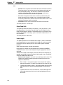
The Printing Process
Thermal Printer Technology
Quiet and fast, with excellent print quality, your multifunction thermal printer
uses an inline thermal printhead. The thermal printer operates differently from
a line matrix or laser printer, because the thermal printer uses a printhead with
heating elements and special paper or ribbon.
The Printing Process
The thermal printhead allows two modes of operation:
•
Direct Thermal
During direct thermal printing, the thermal printhead selectively heats
small, rectangular thermal dots. When these contact the coated thermal
paper, the dyes and developers in the coating react to the heat and
develop an image. This mode of printing is generally used for short-term
labeling applications.
•
Thermal Transfer
During thermal transfer printing, the heated thermal dots contact a
thermal ribbon. The heat reacts with the ribbon and bonds the image to
the paper. This method is used especially for abrasive, long-storage
applications and for specialized applications, such as in extreme
environmental conditions or where tamper-proofing is required.
NOTE: Thermal transfer is not supported on 4 inch DT model printers.
Dynamic Print Control
Dynamic print control is a unique feature of your thermal printer that provides
excellent print quality by preventing unevenness of print density.
Print quality largely depends on how the thermal paper or the thermal ribbon
and thermal transfer paper responds to the heat of the thermal printhead.
During printing, the thermal printhead must reach a set temperature in the
shortest possible time. Then it must cool down to the original temperature in
the shortest possible time after printing. Thus print quality is dependent on the
precise control of the energy supplied to the thermal dots.
The dynamic print control is a method for predicting the quantity of heat
required to print dots based on the results of the previous printing. This
prevents unevenness of print density and results in the printing of narrowladder bar codes or vertical grid lines that are straight from the microscopic
viewpoint.
27
Chapter
1
Thermal Consumables
Thermal Consumables
Media Selection
Since there are two print modes of operation, there are two kinds of thermal
media:
•
•
Direct thermal media
Thermal transfer media
Direct thermal media is paper coated with special chemicals that act as an
accelerator, acceptor dye, and binder. During direct thermal mode, the heat
from the thermal printhead contacts the paper and causes a chemical
reaction.
Thermal transfer media requires ribbon. A wide range of Printronix thermal
transfer media is available, such as film or synthetic paper substitutes. Most
of these media options can be die-cut for easy label applications. The wide
selection of media sizes and face stocks have been tested with Printronix
ribbons for print quality and usage. Consult your Genuine Printronix Supplies
Catalog, call the Printronix Customer Solutions Center at (714) 368-2686, or
access the Printronix web page at www.printronix.com.
NOTE: The term “media” used in this manual refers to all the different kinds
of paper or tag stock that can be used in the printer.
See “Genuine Printronix Media” on page 349 for more information.
Ribbons
Printronix offers a wide range of ribbons specifically engineered to enhance
printing capabilities and to prevent premature printhead wear. Therefore, you
should use a Genuine Printronix Thermal Ribbon in your printer.
See “Genuine Printronix Thermal Transfer Ribbons” on page 348 for more
information.
28
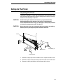
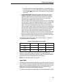
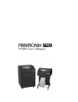
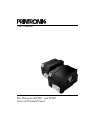
Unpacking The Printer
Setting Up The Printer
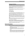
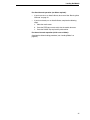
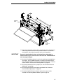
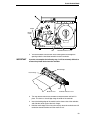
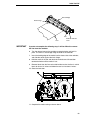
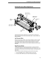
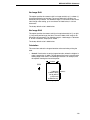
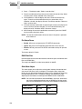
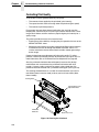
Unpacking The Printer
The printer is shipped in a carton and protective bag. The top lid of the carton
has instructions for removing the internal packing material. Keep all packing
material in case repacking is required.
CAUTION
Avoid touching the electrical connectors to prevent electrostatic
discharge damage while setting up the printer. The discharge of
accumulated electrostatic energy can damage or destroy the printhead
or electronic components used in this device.
CAUTION
Do not place the printer on its backside during unpacking or handling,
because you may damage the printer interface connector.
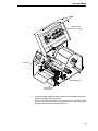
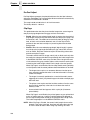
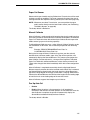
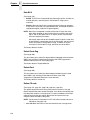
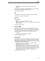
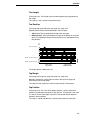
Frame
Media Cover
Tape Strips (2)
Foam Pads (2)
1. Remove the tape strips from the media cover. Lift open the media cover.
2. Remove the tape securing the foam pad to the inside of the media cover.
3. Remove the foam pad between the front door and the frame.
29
Chapter
1
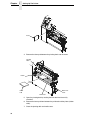
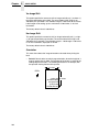
Setting Up The Printer
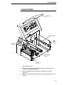
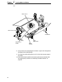
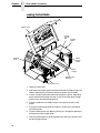
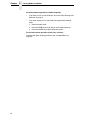
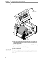
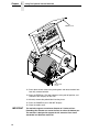
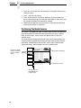
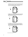
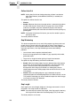
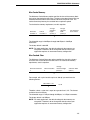
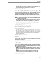
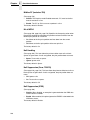
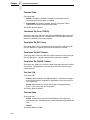
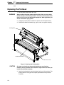
Foam
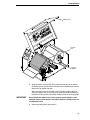
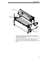
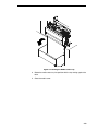
4. Remove the foam pad between the pivoting deck and the frame.
Pivoting
Deck
Platen
Foam
Pad
Deck Lock
Lever
Printhead
5. Open the pivoting deck by rotating the blue deck lock lever fully
clockwise.
6. Remove the foam pad from between the printhead and the platen (rubber
roller).
7. Close the pivoting deck and media cover.
30
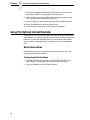
Installation
Installation
The following sections will guide you through the printer installation process.
1. Place the printer on a flat level surface that allows easy access to all sides
of the printer.
CAUTION
Never operate the printer while it is resting on its side or upside down.
2. Check that the printer power switch is in the OFF (O) position.
WARNING
Failure to properly ground the printer may result in electric shock to the
operator.
In compliance with international safety standards, this printer has been
equipped with a three-pronged power cord. When inserted in a correctly
wired power outlet, the ground conductor will ensure that the printer
chassis is at ground (earth) potential. Do not use adapter plugs or
remove the grounding prong from the cable plug. If an extension cord is
required, ensure that a three-wire cable with a properly grounded plug is
used.
3. Attach the AC power cord to the AC power receptacle in the back of the
printer.
CAUTION
Verify the required voltage on the printer’s model number label on the
rear of the printer.
4. Attach the AC power cord to a grounded (three prong) electrical outlet of
the proper voltage.
31
Chapter
1
Setting Up The Printer
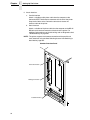
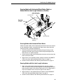
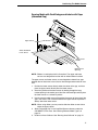
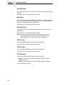
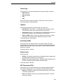
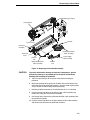
5. Attach Interface:
a. Parallel Interface
Attach a suitable parallel printer cable from the computer to the
Centronics/IEEE 1284 interface connector at the back of the printer.
Snap the bail locks to the Centronics connector to secure the
interface cable to the printer.
b. Serial Interface
Attach a suitable serial printer cable from the computer to the DB-25
RS-232 serial interface connector at the back of the printer. For
additional information on serial cable wiring, refer to “Diagnostics And
Troubleshooting” on page 307.
NOTE: The printer supports simultaneous connection of the parallel and
serial interfaces using the Auto Switching feature. Auto Switching is
described on page 299.
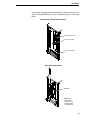
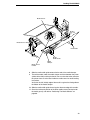
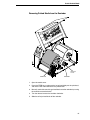
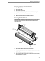
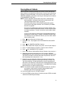
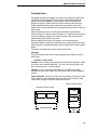
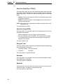
Standard Interface Panel
Serial Connection
Debug Connection
Parallel Interface
32
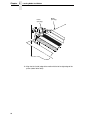
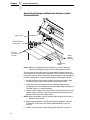
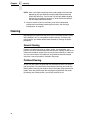
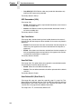
Installation
If your printer is equipped with the Coax/Twinax, Network Interface Card
(NIC), or Dual NIC interfaces, the rear I/O panel will appear as illustrated
below.
Coax/Twinax and NIC Interface Panel
Twinax Connection
Coax Connection
NIC Connection
Dual NIC Interface Panel
Dual NIC
Note: This
illustration is
shown with an
optional Radio
Card installed.
33
Chapter
1
Setting Up The Printer
c.
Coax Connection
Attach a suitable coaxial cable from the computer to the coax
connector located in the I/O plate in the back of the printer.
d. Twinax Connection
Attach a suitable twinax cable from the computer to the twinax
connector located in the I/O plate in the back of the printer.
e. NIC Connection
Insert a suitable NIC cable from your hub or switch to the NIC
connector located in the I/O panel in the rear of your printer.
34
2
Operation
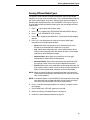
Controls And Indicators
Power Switch
The power switch is located on the bottom back panel of the printer. To apply
power, place the switch in the | (ON) position. When you first power on the
printer, a series of initialization messages will appear on the Liquid Crystal
Display (LCD) on the control panel.
To remove power, place the power switch in the O (OFF) position.
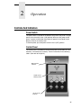
Control Panel
The control panel is located on the front of the printer and includes an LCD,
indicators, and control keys (buttons). These are described in the following
tables. (Also refer to Chapter 3.)
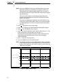
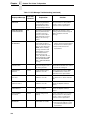
Online Status
Indicator
OFFLINE
Liquid Crystal
Display (LCD)
Job In Process
Indicator
35
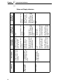
36
Indicates when the
printer is online, offline,
or when there is a fault
condition.
A backlighted liquid
crystal display with two
rows of 16 characters
each.
Indicates when the
printer is receiving or
processing data.
Liquid Crystal
Display (LCD)
Job In Process
Description
Online Status
Indicator
Flashes during a fault
condition.
Displays “OFFLINE”
and a main menu,
submenu, or option.
During a fault
condition, displays the
specific fault message
and the corrective
action.
None
Flashes during a fault
condition.
Displays “OFFLINE.”
During a fault
condition, displays the
specific fault message
and the corrective
action.
Flashes when
receiving data.
Stays lit when data has
been processed and is
waiting to be printed.
Off when no data is
being received or when
no data remains in the
buffer.
Flashes during a fault
condition.
Displays “ONLINE,” the
interface type, and
emulation in use.
During a fault condition,
displays the specific
fault message and the
corrective action.
Flashes when receiving
data.
Stays lit when data has
been processed and is
waiting to be printed.
Off when no data is
being received or when
no data remains in the
buffer.
Off.
Off when the printer is
offline.
Stays lit when the
printer is online, ready
to print, and accept
data from the host.
Function in
Menu Mode
Function in
Offline Mode
Function in
Online Mode
Chapter
2
Controls And Indicators
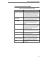
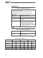
Status and Display Indicators
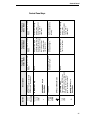
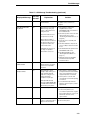
+
-
Button
INCREMENT Key in
Menu Mode
TEST PRINT Key
Pressing the ↵ (ENTER) key
with a Diagnostic Test displayed
initiates the test. Pressing ↵
again terminates the test.
UP Key in Menu Mode
FEED Key
None
Advances the media
one label length.
None
JOB SELECT Key
DECREMENT Key in
Menu Mode
Sets printer to Offline
Mode.
Function in
Online Mode
PAUSE Key
Toggles the printer between
Online and Offline Modes.
Description
Scrolls through the
Test Print patterns.
Advances the media
one label length.
Displays the name
and number of the last
loaded configuration
and allows you to load
the factory and/or
pre-stored printer
configurations.
Sets printer to Online
Mode.
Function in
Offline Mode
Scrolls right through
main menus.
Increments option
values within
submenus.
Scrolls the current
menu selection one
level up.
Scrolls left through
main menus.
Decrements option
values within
submenus.
Sets printer to Offline
Mode.
Function in
Menu Mode
Control Panel
Control Panel Keys
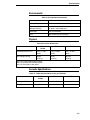
37
Button
38
Takes the printer
Offline and selects the
Menu Mode.
None
MENU Key
ENTER Key
Pressing the ↵ (ENTER) key in
Menu Mode selects the displayed
option or value. An asterisk then
appears next to the option or value
indicating it has been selected.
Note: If the ENTER key is locked,
“ENTER SWITCH LOCKED”
displays on the LCD for one second.
Press the (DOWN) and
↵ (ENTER) keys at the same time to
unlock the ENTER key.
None
Function in
Online Mode
None
Selects the Menu
Mode.
Clears all data in the
printer data buffer
when enabled.
Function in
Offline Mode
Selects the current
menu value and
displays an asterisk
(*) next to the value.
Scrolls between main
menu selections.
Scrolls the current
menu selection one
level down.
Function in
Menu Mode
2
DOWN Key in Menu Mode
CANCEL Key
When the CANCEL key is enabled,
pressing it will clear all data in the
printer buffer and prevent printing of
that data.
Note: The factory default = Disable.
However, when the Coax/Twinax
Interface option is installed, the
factory default = Enable.
Description
Chapter
Controls And Indicators
Control Panel Keys (cont.)
Powering On The Printer
Powering On The Printer
When you power on the printer, it executes a self-test. During the self-test, the
LCD momentarily displays the DPI resolution (203 or 300 DPI) of the installed
printhead. The default power-on state is online. Once the printer has
successfully initialized, the ONLINE status indicator light illuminates, and the
LCD indicates the communication interface selected and the type of
emulation installed.
If there is a fault during the self-test, the ONLINE status indicator flashes, and
a fault message appears on the display. The alarm may also sound, if
configured to do so.
Operating Modes
The current operating mode can be selected through the control panel keys or
can result from routine operations such as powering on the printer.
Online: In online mode, the printer can receive and print data sent from the
host. Pressing the PAUSE key toggles the printer between the online and
offline modes. The ONLINE status indicator is lit in online mode.
Offline: In offline mode, you can perform operator functions such as loading
media or changing ribbon. Pressing the PAUSE key toggles the printer from
offline to online mode. The ONLINE status indicator is not illuminated in offline
mode.
Menu: Pressing the MENU key takes the printer offline and into Menu mode.
In this mode, you can navigate through all configuration and status menus
and change the printer configuration.
Fault: In fault mode, a fault condition exists that must be cleared before
printing can continue. The ONLINE status indicator flashes, the alarm beeps
(if configured to do so), and a descriptive fault message displays.
The fault must be corrected first and then the message cleared by pressing
the PAUSE key before normal printing can continue.
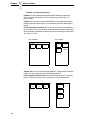
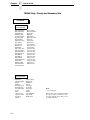
Media Handling Modes
Before you load media, you must decide which media handling mode to use:
•
Continuous. Prints on the media and sends it out the front of the printer.
When the optional internal rewinder is installed, use “Continuous” for
Batch Rewind mode (see page 56).
•
Tear-Off Strip. Prints on the media and sends it out the front until the
print buffer is empty then positions the last label over the tear bar for
removal.
•
Tear-Off. After each label is printed, the printer positions the label over
the tear bar and waits for you to tear off the label before printing the next
label (on-demand printing). A “Remove Label” message will display to
remind you to remove the label before the next one can be printed.
39
Chapter
2
Loading Media And Ribbon
•
Peel-Off. When the optional internal rewinder is installed, the printer
prints and peels die-cut labels from the liner without user assistance. The
label liner is wound on the rewinder. The printer waits for you to take
away the label before printing the next one (on-demand printing). A
“Remove Label” message will display to remind you to remove the label
before the next one can be printed. For Label Peel-off information, see
page 62.
•
Cut. When the optional media cutter is installed, the printer automatically
cuts media after each label is printed or can cut the media after a
specified number of labels have been printed using a software cut
command.
Once you have decided on the mode, configure the printer. See Chapter 3 for
more information.
Loading Media And Ribbon
NOTE: This section describes the procedures for loading various types of
media and ribbon. You can also refer to instructions on the printer
itself, on a label on the inside of the media cover.
The term “media” in this manual refers to all the different kinds of paper, label,
or tag stock material that can be printed on by the printer. Your thermal printer
can print on continuous paper, adhesive backed labels, or non-adhesive tags
packaged in roll or fanfold form.
CAUTION
DO NOT TOUCH the printhead or the electronic components under the
printhead assembly. The discharge of electrostatic energy that
accumulates on the surface of the human body or other surfaces can
damage or destroy the printhead or electronic components used in this
device.
CAUTION
Do not close the pivoting deck without label stock installed between the
printhead and the platen, because debris on the platen may damage the
printhead.
IMPORTANT
Adhesive backed labels that DO NOT lay flat on the liner can jam the
printer. This can cause the label to peel off the liner. The exposed edges
can stick to the label guides and rollers inside the printer.
If you run out of labels while printing, do not turn off the printer while
reloading labels, because you can lose data.
40
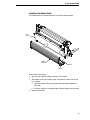
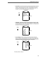
Loading Roll Media
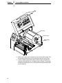
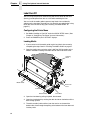
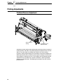
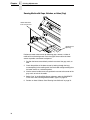
Loading Roll Media
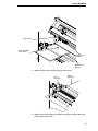
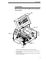
Media Cover
Media Hanger
Media
Hanger
Guide
Pivoting
Deck
Media Width
Guide
Deck Lock
Lever
1. Open the media cover.
2. Slide the blue media hanger guide outward to the end of the media
hanger, and flip it down horizontally.
3. Open the pivoting deck by rotating the blue deck lock lever fully
clockwise.
4. Slide the blue media width guide close to the outside end of the media
damper.
41
Chapter
2
Loading Media And Ribbon
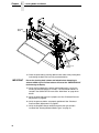
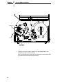
Media Roll
Media Hanger
Media Hanger
Guide
5. Slide a roll of media onto and towards the back of the media hanger. The
media feeds from the top of the roll and towards the front of the printer.
6. Place the media hanger guide under the media hanger and against the
lower part of the label core at a 45 degree angle (as shown). This position
provides the required tension for a new label roll and the desired drag for
a partial label roll.
42
Loading Roll Media
Media Loading
Instruction Label
Printhead
Media Damper
Platen (Rubber
Drive Roller)
7. Thread the media under the media damper and then between the platen
(rubber drive roller) and the printhead.
You can also refer to the arrows on the printer frame or to the label inside
the media cover for media loading instructions.
43
Chapter
2
Loading Media And Ribbon
Media Sensor
Media Guard
Fixed Guide
Media Sensor
Handle
Media
Width Guide
Media
Damper
8. Verify that the left (inside) edge of the media is against the fixed guide on
the bottom of the media damper.
9. Push the blue media width guide in until it is flush with the outer edge of
the media.
10. Check the horizontal position of the lower media sensor (located under
the media guard), and refer to “Positioning The Media Sensors” on
page 68.
44
Loading Roll Media
Upper Sensor
Visible Red Beam
Lower Sensor
Upper Sensor
Handle
Media Guard
Opening
11. Slide the upper sensor directly over the lower sensor.
Platen
(left edge)
Media
(left edge)
12. Align the left (inside) edge of the media with the left straight edge of the
platen (rubber drive roller).
45
Chapter
2
Loading Media And Ribbon
Pivoting
Deck
Deck Lock
Lever
13. Close the printhead by pressing down on both sides of the pivoting deck
and rotating the deck lock lever fully counterclockwise.
IMPORTANT
Ensure the pivoting deck is down and locked before attempting to
advance media or print. Failure to do so will cause the “PRINTHEAD UP”
fault message to display.
14. Verify that Print Mode in the printer configuration menu is set for the
media type installed (Direct or Transfer). The Print Mode submenu is
located in the QUICK SETUP menu. See “Main Menu” on page 92 for
details.
15. Verify the printhead pressure is properly set. See “Printhead Pressure
Adjustment” on page 66.
16. Verify the pressure blocks are properly positioned. See “Printhead
Pressure Block Adjustments” on page 67.
17. Verify the Gap/Mark Sensor selection matches the type of media
installed. See “Sensing Different Media Types” on page 73.
46
Loading Roll Media
For direct thermal operation (no ribbon required):
•
If you have not run an Auto Calibrate, do so now. See “Running Auto
Calibrate” on page 74.
•
If you have already run an Auto Calibrate, complete the following
steps:
a. Close the media cover.
b. Press the FEED key once to verify that the media advances.
c.
Press the PAUSE key to place the printer online.
For thermal transfer operation (which uses a ribbon):
Complete the ribbon loading procedure (see “Loading Ribbon” on
page 53).
47
Chapter
2
Loading Media And Ribbon
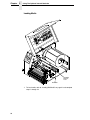
Loading Fanfold Media
Media Cover
Fanfold
Tension
Arm
Fanfold
Media
Pivoting
Deck
Media
Hanger
Guide
Media
Hanger
Bottom Panel
Opening
Deck Lock Lever
1. Open the media cover.
2. Slide the media hanger guide outward to the end of the media hanger and
rotate it downward to a horizontal position to remove any roll media.
3. Place the fanfold media either behind or beneath the printer, depending
on the desired fanfold supply location. Insert the first few labels through
either the rear or bottom panel opening.
4. Place the media over the media hanger, flush against the back of the
printer.
5. Flip up the media hanger guide and slide it in against the outer edge of
the fanfold media.
6. Flip the fanfold tension arm down by pushing on it through the opening at
the top of the media hanger guide.
7. Open the pivoting deck by rotating the deck lock lever fully clockwise until
the deck swings upward.
48
Loading Fanfold Media
Media Sensor
Media Guard
Fixed Guide
Media
Width Guide
Media Sensor
Handle
Media
Damper
8. Slide the media width guide outward to the end of the media damper.
9. Thread the media under the media damper and then between the platen
(rubber drive roller) and the printhead. You can also refer to the arrows on
the printer frame or to the label inside the media cover for media loading
instructions.
Verify that the left (inside) edge of the media is against the fixed guide on
the bottom of the media damper.
10. Slide the media width guide inward against the outer edge of the media.
11. Check the horizontal position of the lower media sensor (located under
the media guard), and refer to “Positioning The Media Sensors” on
page 68.
49
Chapter
2
Loading Media And Ribbon
Platen
(left edge)
Media
(left edge)
12. Align the left (inside) edge of the media with the left straight edge of the
platen (rubber drive roller).
50
Loading Fanfold Media
Pivoting
Deck
Deck Lock
Lever
13. Close the printhead by pressing down on both sides of the pivoting deck
and rotating the deck lock lever fully counterclockwise. This locks the
pivoting deck and printhead assembly into the printing position.
IMPORTANT
Ensure the pivoting deck is down and locked before attempting to
advance media or print. Failure to do so will cause the “PRINTHEAD UP”
fault message to display.
14. Verify that Print Mode submenu is set for the media type installed (direct
or transfer). The Print Mode submenu is located in the QUICK SETUP
menu. See “Main Menu” on page 92 for more information. Also, if thermal
transfer media is installed, see “Loading Ribbon” on page 53.
15. Verify the printhead pressure is properly set. See “Printhead Pressure
Adjustment” on page 66.
16. Verify the pressure blocks are properly positioned. See “Printhead
Pressure Block Adjustments” on page 67.
17. Verify the Gap/Mark Sensor selection matches the type of media
installed. See “Sensing Different Media Types” on page 73.
51
Chapter
2
Loading Media And Ribbon
For direct thermal operation (no ribbon required):
•
If you have not run an Auto Calibrate, do so now. See “Running Auto
Calibrate” on page 74.
•
If you have already run an Auto Calibrate, complete the following
steps:
a. Close the media cover.
b. Press the FEED key once to verify that the media advances.
c.
Press the PAUSE key to place the printer online.
For thermal transfer operation (which uses a ribbon):
Complete the ribbon loading procedure (see “Loading Ribbon” on
page 53).
52
Loading Ribbon
Loading Ribbon
Skip this section for 4 inch DT models or when using direct
thermal printing.
Empty Supply
Core
Ribbon
Take-up
Spindle
Pivoting
Deck
Ribbon
Roll
Ribbon Supply
Spindle
Deck Lock
Lever
1. Install the empty ribbon supply core onto the take-up spindle.
2. Slide the ribbon roll onto the ribbon supply spindle until it stops against
the spindle flange.
3. Open the pivoting deck by rotating the deck lock lever fully clockwise until
the deck swings upward.
53
Chapter
2
Loading Media And Ribbon
Printhead
Media
Rear Ribbon
Guide Roller
4. Thread the end of the ribbon under the rear ribbon guide roller, then
between the platen and the printhead.
You can also refer to the arrows on the printer frame or to the label inside
the media cover for media loading instructions.
54
Loading Ribbon
Media Cover
Take-up
Core
Take-up
Spindle
5. Wrap the ribbon from the front of the printhead assembly to the front of
the ribbon take-up spindle. Attach the ribbon to the fiberboard core on the
ribbon take-up spindle with tape.
When installing a new roll of ribbon, attach the ribbon leader adhesive
strip to the ribbon take-up core. Manually rotate the spindle clockwise to
feed the unusable portion of the ribbon leader around the take-up spindle.
IMPORTANT
Do not attach the ribbon to the ribbon take-up spindle without a core
installed. Proper ribbon tension and ribbon removal is based on the use
of a fiberboard core.
6. Close the pivoting deck (see page 51).
55
Chapter
2
Using The Optional Internal Rewinder
7. Verify that Print Mode (in the QUICK SETUP menu) is set for Transfer.
See “QUICK SETUP” on page 100 for more information.
8. If you have not run an Auto Calibrate with this media and ribbon, do so
now. See “Running Auto Calibrate” on page 74.
9. Press the FEED key once to verify that the media and ribbon advance.
10. Press the PAUSE key to place the printer online.
11. Close the printer media cover if the rewinder is not needed.
Using The Optional Internal Rewinder
The printer can be set up to rewind labels after they have been printed (Batch
Rewind Mode) or to automatically peel labels from their backing and dispense
them one at a time while rewinding the liner (Peel-Off Mode). Both modes
require an internal rewinder, which is available as a factory installed option
only.
Batch Rewind Mode
Batch Rewind allows you to automatically rewind printed labels into a roll
using the optional internal rewinder.
Configuring the Printer Menu
1. Set Media Handling to “Continuous” under the QUICK SETUP menu.
(See Chapter 3, “Configuring The Printer” for more information.)
2. Press the PAUSE key until “OFFLINE” displays.
56
Batch Rewind Mode
Installing The Media Guide
The media guide must be installed when using Batch Rewind mode.
Front
Door
Media
Guide
Hook
Groove
To install the media guide:
1. Open the front door by pulling it upwards, then forward.
2. The bottom of the plastic media guide is shaped like a hook and the top
has a groove:
a. Hook the bottom of the media guide under the bottom edge of the
front door.
b. Snap the groove on the media guide to the top edge of the front door.
3. Close the front door.
57
Chapter
2
Using The Optional Internal Rewinder
Loading Media
Rewinder
Release
Lever
Rewinder
1. To load media, refer to “Loading Roll Media” on page 41 and complete
steps 1 through 10.
58
Batch Rewind Mode
Media
Media
Guide
Slot
Rewinder Release Lever
2. Thread the media over the front of the media guide and through the
opening under the front door toward the internal rewinder.
IMPORTANT
If you do not complete the following step, it will be extremely difficult to
remove the printed labels from the rewinder.
Raised Ridge
Back Flange
Slot
Media or Liner
Rewinder Release Lever
3. Turn the release lever on the rewinder counterclockwise and lock it in
place. This forms a raised ridge along the width of the rewinder.
4. Insert the leading edge of the media into the closest slot of the rewinder,
and slide the media against the back flange.
5. Hold the media edge in the slot and manually rotate the rewinder one full
revolution counterclockwise until the media is taut.
59
Chapter
2
Using The Optional Internal Rewinder
Media Cover
Deck Lock
Lever
6. Press down on both sides of the pivoting deck and rotate the deck lock
lever counterclockwise against its stop to place the printhead assembly
into the printing position.
7. Press the FEED key to advance the media to the next TOF (Top-of-Form)
position.
8. Press the PAUSE key until “ONLINE” displays.
9. Close the media cover.
IMPORTANT
60
The rewinder supports a maximum diameter of five inches of printed
labels. Exceeding this diameter can cause printed labels to rub on the
bottom pan.
Batch Rewind Mode
Removing Printed Media from the Rewinder
Release
Lever
Printhead
Rewinder
1. Open the media cover.
2. Press the FEED key to advance the last printed label past the printhead,
and tear the liner from behind the last printed label.
3. Manually rewind the remaining printed labels onto the rewinder by turning
the rewinder counterclockwise.
4. Turn the release lever on the rewinder clockwise.
5. Slide the roll of printed labels off the rewinder.
61
Chapter
2
Using The Optional Internal Rewinder
Label Peel-Off
You can set up the printer to automatically peel die-cut labels off their liner
(backing) and dispense them one at a time while rewinding the liner.
You can install the media guide to prevent long labels from accidentally
adhering to the front door assembly, but it is normally not needed when using
labels less than two inches long (see “Installing The Media Guide” on
page 57).
Configuring the Printer Menu
1. Set Media Handling to “Peel-Off” under the QUICK SETUP menu. (See
Chapter 3, “Configuring The Printer” for more information.)
2. Press the PAUSE key until “OFFLINE” displays.
Loading Media
1. If you want to install the media guide to print long labels, do so now by
completing the steps listed in “Installing The Media Guide” on page 57.
2. Open the media cover and refer to the Label Peel-Off illustration on the
Ribbon and Media Loading instruction label on the inside of the cover.
Pivoting
Deck
Media Guide
Deck Lock
Lever
Tear Bar
Bottom Roller
Front Door
3. Open the front door by pulling it upward, then forward.
4. Open the pivoting deck by rotating the deck lock lever clockwise until the
deck swings upward.
5. Thread the media (label and liner) over the tear bar and around the
bottom roller, then through the opening at the bottom of the front door and
into the printer.
62
Label Peel-Off
Raised Ridge
Back Flange
Slot
Liner
IMPORTANT
Rewinder Release
Lever
If you do not complete the following step, it will be difficult to remove
the liner from the rewinder.
6. Turn the release lever on the rewinder counterclockwise and lock it in
place. This forms a raised ridge along the width of the rewinder.
7. Insert the leading edge of the media into the closest slot of the rewinder,
and slide the media against the back flange.
8. Hold the media in the slot and rotate the rewinder one full revolution
counterclockwise until the media is taut.
9. Remove labels from the liner so that behind the tear bar the liner is void of
labels for about 1.5 inches and below the tear bar for about 2 inches.
10. Close the front door.
11. Complete the media routing as shown above.
63
Chapter
2
Using The Optional Internal Rewinder
Media Cover
Deck Lock
Lever
12. Press down on both sides of the pivoting deck and rotate the deck lock
lever fully counterclockwise.
13. Press the FEED key. The label advances to the peel-off position, and
“Remove Label” displays on the LCD.
14. Manually remove the peeled label from the printer.
15. Press the PAUSE key until “ONLINE” displays.
16. Close the media cover.
IMPORTANT
64
The rewinder supports a maximum diameter of 5 inches of liner.
Exceeding this diameter can cause the liner to rub on the bottom pan.
The rewinder is designed to support the full amount of liner from a
standard 8 inch diameter media roll.
Removing The Media Guide
Removing Label Liner from the Rewinder
1. Open the media cover.
2. Open the front door.
3. Tear the liner at the tear bar.
4. Manually rewind the remaining liner onto the rewinder by turning the
rewinder counterclockwise.
5. Turn the release lever on the rewinder clockwise.
6. Slide the roll of label liner off the rewinder and discard.
Removing The Media Guide
Remove the media guide from the front door when using Tear-Off or Tear-Off
Strip media handling, because you will need to tear the label downward
against the tear bar.
Tear Bar
Front
Door
Media
Guide
Hook
Groove
1. Open the front door by pulling it upward, then forward.
2. Grasp the upper right corner of the media guide and pry it off of the top of
the front door.
3. After removing the media guide, close the front door.
4. Open the pivoting deck and load paper and ribbon normally (see “Loading
Media And Ribbon” on page 40).
65
Chapter
2
Printing Adjustments
Printing Adjustments
Printhead Pressure Adjustment
Active Pressure
Setting
Printhead Pressure
Adjustment Dial
Sometimes you will need to adjust printhead pressure because of variations in
media thickness and width. The printhead pressure adjustment dial is shown
above. The value shown at the bottom of the dial is the active setting.
In general, adjust printhead pressure to the lowest value which produces the
desired print quality. Die cut labels usually require a setting of 4, while heavy
stock requires a setting of 6 to max. The numbers on the printhead pressure
adjustment lever are relative only and do not indicate a specific printhead
pressure or media thickness. By following this procedure, you will minimize
printhead wear.
66
Printhead Pressure Block Adjustments
Printhead Pressure Block Adjustments
Pressure Block
Adjustment Scale
Right Pressure
Block Pointer
Lead Screw
Knob
Left
Pressure
Block
Left Pressure
Block Handle
Right Pressure
Block
Printhead pressure block adjustments are used to obtain a uniform print
density across the width of the installed media under a variety of media and
ribbon conditions.
Left Pressure Block
Under normal printing conditions, the left block should be set with its handle
aligned with the bold mark on the pressure block adjustment scale. When
using media or ribbon widths less than one-third the printer’s maximum
printing width, you may need to manually slide the left pressure block further
to the left.
Right Pressure Block
The right pressure block should be positioned with its pointer (handle on
4 inch printer models) near the right edge of the media or ribbon in use. Turn
the lead screw knob clockwise to move the block right or counterclockwise to
move it left.
Check the pressure block positioning by printing the Grey test pattern:
1. Press the PAUSE key until “OFFLINE” appears on the LCD.
2. Press the TEST PRINT key until “Printer Tests/Grey” displays.
67
Chapter
2
Printing Adjustments
3. Press the ↵ key to start the Grey test pattern. The pattern will start and
continue to print.
4. Press ↵ again to stop printing.
5. Check the test pattern. If necessary reposition the pressure blocks to
obtain a uniform print density across the media width. In most cases, only
the right pressure block may need to be adjusted.
6. Whenever you reposition a pressure block, run the Grey test pattern to
verify the print pattern is acceptable.
Positioning The Media Sensors
Your printer is equipped with upper and lower media sensors that detect the
top-of-form position on media with label length indicators (gaps, notches,
holes, or black marks). These sensors also detect when a Paper Out
condition exists.
The media sensors should not be placed in the path of media features that
could cause false gap detection or paper out faults. Such features are dark
pre-printing, rounded die-cut label corners, vertical gaps associated with
side-by-side labels, and extraneous cut-outs, as shown below.
Position the media
sensors in either of
the grey shaded
areas.
Dark Pre-printing
Extraneous Cut-out
Vertical Gap and
Rounded Die-cut
Label Corners
68
Positioning The Media Sensors
Sensing Media with Horizontal Black Marks (Mark) or
Media with No Label Length Indicators (Disable)
Visible Red Beam
from Lower Sensor
Lower Sensor
Black Mark
(underside
of media)
Sensor Handle
Media Guard
Opening
Sensing Media with Horizontal Black Marks
Position the lower media sensor for detecting horizontal black marks located
on the underside of media, and position the upper sensor above the lower
sensor to provide a consistent background.
1. Check the position of the sensor by looking through the long, narrow
opening in the media guard. Use the visible red light emitting from the
lower sensor as a reference pointer.
2. Use the sensor handle to manually position the sensor to the center of the
black mark on the media.
3. Select “Mark” in the Gap/Mark Sensor submenu under the CALIBRATE
CTRL menu. See “Sensing Different Media Types” on page 73.
4. Perform an Auto Calibrate. See “Running Auto Calibrate” on page 74.
Sensing Media with No Label Length Indicators
1. When using media without label length indicators (no gaps, notches,
holes, or marks) or when you want to ignore all existing length indicators,
place the lower sensor in the center of the media so it can detect when a
Paper Out condition exists. Also set the upper sensor above it.
2. Select “Disable” in the Gap/Mark Sensor submenu under CALIBRATE
CTRL. See “Sensing Different Media Types” on page 73.
3. Perform an Auto Calibrate. See “Running Auto Calibrate” on page 74.
69
Chapter
2
Printing Adjustments
Sensing Media with Gaps, Notches, or Holes (Gap)
Visible Red Beam
from Lower Sensor
Media Guard
Opening
Position the lower media sensor for detecting gaps, notches, or holes in
media with a white background. Place the upper sensor above the lower
sensor to provide a consistent background.
1. Position the lower sensor directly under the center of the gap, notch, or
hole.
2. Check the position of the lower sensor by looking through the long,
narrow opening in the media guard. Use the visible red light emitting from
the lower sensor as a reference pointer.
3. Use the sensor handle to manually position the sensor to the center of the
gap, notch, or hole in the media.
4. Select “Gap” in the Gap/Mark Sensor submenu under the CALIBRATE
CTRL menu. See “Sensing Different Media Types” on page 73.
5. Perform an Auto Calibrate. See “Running Auto Calibrate” on page 74.
70
Positioning The Media Sensors
Sensing Media with Dark Background Labels with Gaps
(Advanced Gap)
Upper Sensor
Visible Red Beam
Lower Sensor
Upper Sensor
Handle
Media Guard
Opening
NOTE: Ribbon is not displayed in this illustration. The upper and lower
sensors are designed to function with or without ribbon installed.
The upper sensor and lower sensor are used together to detect liner gaps
between die cut labels that have a black or dark background on white or clear
liner.
1. Position the lower sensor directly under the center of the gap, and then
place the upper sensor directly over the lower sensor.
2. Check the position of the lower sensor by looking through the long,
narrow opening in the media guard. Use the visible red light emitting from
the lower sensor as a reference pointer.
3. Use the sensor handle to manually position the sensor to the center of the
gap in the media. Then use the handle on the upper sensor to position it
directly above the lower sensor.
NOTE: When using ribbon, you may need to slide the ribbon to one side to
adjust the upper sensor.
4. Select “Advanced Gap” in the Gap/Mark Sensor submenu under the
CALIBRATE CTRL menu. See “Sensing Different Media Types” on
page 73.
5. Perform an Auto Calibrate. See “Running Auto Calibrate” on page 74.
71
Chapter
2
Printing Adjustments
Sensing Dark Background Media with Notches or Holes
(Advanced Notch)
Upper Sensor
Visible Red Beam
Lower Sensor
Black line
on underside
of media
Media
Guard
Opening
Upper Sensor
Handle
NOTE: Ribbon is not displayed in this illustration. The upper and lower
sensors are designed to function with or without ribbon installed.
The upper sensor and lower sensor are used together to detect notches or
holes in media with a black or dark underside. This combination can be found
on tag stock that has a black vertical line along one edge on the underside of
the label, interrupted by a notch or hole used as the label length indicator.
1. Position the lower sensor directly under the center of the notch or hole,
and then place the upper sensor directly over the lower sensor.
2. Check the position of the lower sensor by looking through the long,
narrow opening in the media guard. Use the visible red light emitting from
the lower sensor as a reference pointer.
3. Use the sensor handle to manually position the sensor to the center of the
notch or hole in the media. Then use the handle on the upper sensor to
position it directly above the lower sensor.
NOTE: When using ribbon, you may need to slide the ribbon to one side to
adjust the upper sensor.
4. Select “Advanced Notch” in the Gap/Mark Sensor submenu under the
CALIBRATE CTRL menu. See “Sensing Different Media Types” on
page 73.
5. Perform an Auto Calibrate. See “Running Auto Calibrate” on page 74.
72
Sensing Different Media Types
Sensing Different Media Types
The printer’s media sensors can detect the different types of label length
indicators on a large variety of media types. This is accomplished by selecting
the correct sensor option: Gap, Mark, Advanced Gap, Advanced Notch, or
Disable under Gap/Mark Sensor in the CALIBRATE CTRL menu. Figure 13
on page 339 illustrates the different media types and label length indicators
used on them.
1. Press
..
.
to place the printer in Menu mode.
2. Press ↓ and ↵ together until “ENTER SWITCH UNLOCKED” displays.
3. Press
..
.
until “CALIBRATE CTRL” displays.
4. Press ↓ until “Gap/Mark Sensor/Disable*” (the currently enabled) option
displays.
5. Press + or - until the option that matches the type of label length
indicators on the installed media displays:
•
Mark. Select when using media that has horizontal black marks
located on the underside of the label liner or tag stock.
•
Gap. Select when using media with a liner space between die-cut
labels or when using tag stock with notches or holes as label length
indicators on white background media.
•
Advanced Gap. Select when using media that has liner gaps
between die cut labels with black background.
•
Advanced Notch. Select when using media with notches or holes
that interrupt a black vertical line on the underside of the media.
•
Disable. Select when using media with no label length indicators (no
gaps, notches, holes, or black marks) or when you want the printer to
ignore all existing label length indicators on the installed media.
NOTE: When you select Disable, the length of each label is based on the
Label Length value entered in the QUICK SETUP menu or the value
sent via host software.
NOTE: If the printer detects a false PAPER OUT message when you change
from Advanced Gap or Advanced Notch to Gap or Mark sensing or
vice-versa, press the PAUSE key and run Auto Calibrate.
6. Press ↵ to enable the displayed option. An asterisk (*) appears next to
the selection.
7. Press PAUSE until “OFFLINE” appears on the LCD.
8. Review “Calibrating The Media Sensors” on page 74.
9. Perform the Auto Calibrate procedure on page 74.
73
Chapter
2
Printing Adjustments
Calibrating The Media Sensors
Due to manufacturing differences in media and ribbon, the media sensors
may have difficulty differentiating between the label and the liner or the label
and the black mark. When this occurs, the printer may intermittently skip a
label or display a fault message such as “GAP NOT DETECTED/See Manual”
or “PAPER OUT/Load Paper.”
Media sensor sensitivity and reliability can be improved by changing the
Gap/Mark Threshold and/or Paper Out Threshold values. You can change
these values automatically by performing the Auto Calibrate or Manual
Calibrate procedure in the CALIBRATE CTRL menu or change them manually
by entering your own Gap/Mark Threshold or Paper Out Threshold values.
(The changes take effect immediately within the current configuration menu.)
Auto or Manual Calibrate is completed successfully when the displayed
Sensed Distance value correctly matches that of the installed media. When
Gap is selected, the Sensed Distance should match the length from the
trailing edge of one gap to the trailing edge of the next gap (or one label + one
gap). When Mark is selected, the Sensed Distance should match the length
from the leading edge of one black mark to the leading edge of the next black
mark.
When you have completed Auto or Manual Calibrate, you can verify the new
values are correct by pressing the FEED key several times. Each time you
press FEED, media advances one label and stops at the correct Top-of-Form
position of the next label.
Once you confirm the correct values, save them to the desired configuration
menu before powering off the printer. See “Saving A Configuration” on
page 84.
Running Auto Calibrate
You can initialize Auto Calibrate via the TEST PRINT key (described in detail
below) or via the CALIBRATE CTRL or DIAGNOSTIC menus in Menu mode.
NOTE: Verify that the Gap/Mark Sensor option (Gap, Mark, Advanced Gap,
Advanced Notch, or Disable) matches the installed media. See
“Sensing Different Media Types” on page 73.
Check that the media sensors are horizontally positioned to permit
sensing of the label length indicators. See “Positioning The Media
Sensors” on page 68.
If you try to do an Auto Calibrate when Peel-Off Media Handling is
enabled, the LCD will display “CANNOT CALIBRATE/Disable PeelOff.” Before you can do an Auto Calibrate, you must select another
media handling mode.
1. Press the PAUSE key until “OFFLINE” appears on the LCD.
2. Press ↓ and ↵ together until “ENTER SWITCH UNLOCKED” displays.
3. Press the TEST PRINT key until “Printer Tests/Auto Calibrate” displays.
4. Press ↵. Media advances until it can accurately detect the label length
indicators and then stops at the Top-of-Form position. The Sensed
Distance value will then display for one second.
74
Running Media Profile
5. Auto Calibrate is successful when the Sensed Distance value correctly
matches that of the installed media:
•
Gap/Mark Sensor = Gap, Advanced Gap, or Advanced Notch:
The Sensed Distance value is the physical length of one label plus
the length of one gap, notch, or hole.
•
Gap/Mark Sensor = Mark: The Sensed Distance value is the
physical distance from the leading edge of one black mark to the
leading edge of the next.
•
Gap/Mark Sensor = Disable: Not applicable. If Gap/Mark Sensor is
set to Disable, the Sensed Distance value will not be updated.
If “GAP NOT DETECTED” displays, run Auto Calibrate again.
If Auto Calibrate continues to end with an incorrect Sensed Distance
value displayed or a fault message displayed, run Manual Calibrate as
described on page 77 or see Table 17 on page 323.
NOTE: The amount of media sampled during Auto Calibrate is based on the
length of a label and transitions detected, without error, between a
label and its label length indicators.
6. Press the PAUSE key until “OFFLINE” displays.
7. Press the FEED key several times. Each time you press FEED, the media
advances one label length and stops.
NOTE: After a form feed, the position of the leading edge of the next label
depends on the type of Media Handling mode selected under the
QUICK SETUP menu. Tear-Off and Tear-Off Strip Media Handling
will position the label edge at the tear bar, while Continuous will
position the label edge under the printhead.
8. Press the PAUSE key until “ONLINE” displays.
9. Once the Sensed Distance value is confirmed, you will need to save it to
the desired configuration menu before powering off the printer. See
“Saving A Configuration” on page 84.
Running Media Profile
The Media Profile printout shows the relationship of the Paper Out Threshold
and the Gap/Mark Threshold values, illustrates if and when each label length
indicator is detected, and shows the difference between the label length
indicators and the label. The profile printout (see Figure 1 on page 76) helps
you set the thresholds for difficult media. This includes pre-printed labels and
labels with poor gap/media dynamic range.
Once Media Profile is initiated, the printer will continue to advance media and
print the profile in landscape orientation until you press ↵ to stop printing.
75
Chapter
2
Printing Adjustments
NOTE: Verify the CALIBRATE CTRL menu Gap/Mark Sensor option (Gap,
Mark, Advanced Gap, Advanced Notch, or Disable) matches the
installed media. See “Sensing Different Media Types” on page 73.
You will need a minimum installed label width of two inches to support
the Profile printout.
Ensure the media sensors are horizontally positioned to permit
sensing of the label length indicators. See “Positioning The Media
Sensors” on page 68.
Ensure the Print Mode option selected in the QUICK SETUP menu
matches the media installed. Select “Direct” for heat sensitive media
(no ribbon required) or “Transfer” for thermal transfer media (ribbon
required).
1. Press
..
.
to place the printer in Menu mode.
2. Press ↓ and ↵ together until “ENTER SWITCH UNLOCKED” displays.
3. Press
..
.
until “CALIBRATE CTRL” displays.
4. Press ↓ until “Media Profile/Profile Print” displays and then press ↵. (The
printer will continue to print the profile until you press ↵.)
The printer will advance media and continue to print a dynamic profile
image depicting the relationship of the label and any label length
indicators detected.
5. Press ↵. The printer will stop printing.
6. Press the PAUSE key until “OFFLINE” displays.
NOTE: The Gap/Mark and Paper Out Threshold values shown on the Profile
printout represent the last values determined from a successful Auto
or Manual Calibrate or the factory default values if no Auto or Manual
Calibrate was performed.
255
191
Paper Out(144)
127
Gap Mark(105)
063
000
Figure 1. Media Profile Printout
76
Running Manual Calibrate
Running Manual Calibrate
Manual Calibrate should be performed only when the values derived from
Auto Calibrate fail to improve the media sensors’ ability to sense label length
indicators on the installed media. You must first enable “Admin User” in the
PRINTER CONTROL menu before accessing or initializing Manual Calibrate
in the CALIBRATE CTRL menu.
NOTE: Verify the Gap/Mark Sensor option (Gap, Mark, Advanced Gap,
Advanced Notch, or Disable) matches the installed media. See
“Sensing Different Media Types” on page 73.
Ensure the media sensors are horizontally positioned to permit
sensing of the label length indicators. See “Positioning The Media
Sensors” on page 68.
Ensure the Print Mode option selected in the QUICK SETUP menu
matches the media installed. Select “Direct” for heat sensitive media
(no ribbon required) or “Transfer” for thermal transfer media (ribbon
required).
If you try to do a Manual Calibrate when Peel-Off Media Handling is
enabled, the LCD will display, “CANNOT CALIBRATE/Disable PeelOff.” Before you can do a Manual Calibrate, you must select another
media handling mode.
1. Press
..
.
to place the printer in Menu mode.
2. Press the ↓ and ↵ keys together until “ENTER SWITCH UNLOCKED”
displays.
3. Press
..
.
until “PRINTER CONTROL” displays.
4. Press ↑ until “Admin User” displays, then press + until “Enable” displays.
5. Press ↵ to select Enable. An asterisk (*) appears next to “Enable.”
6. Press
..
.
until “CALIBRATE CTRL” displays.
7. Press ↓ until “Manual Calibrate/Run Calibrate” displays, then press the ↵.
8. Follow the instructions displayed on the LCD. Example: “REMOVE
RBN&MEDIA/Press Enter” indicates that you must open the pivoting deck
and remove the ribbon and media from under the printhead, close and
lock the pivoting deck, and press the ↵ key.
9. During the last step of Manual Calibrate, the printer will advance the
media and attempt to detect the label length indicators and stop at the
Top-of-Form position. The Sensed Distance value will then display for
one second. The calibrate is successful when the Sensed Distance value
correctly matches that of the installed media. If “CALIBRATION FAIL/See
Manual” displays, run Manual Calibrate again.
NOTE: The amount of media sampled during Manual Calibrate is based on
the length of a label and the transitions detected without error,
between a label and its label length indicators.
10. Press the PAUSE key until “OFFLINE” displays.
11. Press the FEED key several times. Each time you press FEED, the media
advances one label length and stops.
77
Chapter
2
Cleaning
NOTE: After a form feed, the position of the leading edge of the next label
depends on the type of Media Handling mode selected under the
QUICK SETUP menu. Tear-Off and Tear-Off Strip Media Handling
positions the label edge at the tear bar, while Continuous positions
the label edge under the printhead.
12. Once the correct values are confirmed, save them to the desired
configuration menu before powering off the printer. See “Saving A
Configuration” on page 84.
Cleaning
Depending on the media used, the printer may accumulate residues (media
dust, adhesives, etc.) as a by-product of normal printing. To maintain top
printing quality, you should remove these residues by cleaning the printer
periodically.
General Cleaning
Perform a periodic cleaning on all rollers, guides, and assemblies. Low
pressure air can be used to remove dust in the printer. Isopropyl alcohol and a
cotton swab should be used to clean any areas where media dust, adhesives,
etc. have accumulated. The media path and printhead should be cleaned
each time a new roll of media is installed in the printer.
Printhead Cleaning
As you use your printer, the printhead may become dirty which can result in
poor print quality. You should clean the printhead each time you install new
ribbon (thermal transfer print mode) or install new media (direct thermal print
mode). Clean the printhead with the cleaning pen supplied with the printer.
By keeping your printhead clean, you will help maintain its life.
78
Printhead Cleaning
Pivoting
Deck
Printhead
Elements
Deck Lock
Lever
1. Rotate the deck lock lever clockwise to open the pivoting deck and
remove any media and ribbon (if loaded) to gain access to the printhead
assembly heating element area.
2. Gently rub the felt tip of the cleaning pen or a cotton swab with Isopropyl
alcohol across the printhead heating elements (light brown area).
3. Allow the printhead to dry for one minute before reloading the media and
ribbon.
79
Chapter
80
2
Cleaning
3
Configuring The Printer
Overview
This chapter provides information about:
•
•
•
Setting, saving, modifying, and printing configurations
Configuration menus
Downloading emulation and operating system software
Setting Printer Configuration Parameters
Configuration parameters are set from the control panel or are retrieved from
the printer’s memory. The parameters define how the printer will respond to
command and interface signals from the host computer.
The configuration menu structure consists of main menus and the options
applicable to each menu.
NOTE: Some configurations refer to printer options that may not be present
in your printer. If you select an option or feature that is not present, no
action will be performed by the printer or an “OPTION NOT
INSTALLED” message will display on the LCD.
81
Chapter
3
Overview
Moving Within The Configuration Menu
You can move through the configuration menus using the appropriate
navigation keys, as shown in Figure 2. (See “Controls And Indicators” on
page 35 for more details on the function of the operator panel keys.)
You can select different options and save them as the power on default;
however, you can only save them to configuration menus 1-8. The factory
configuration menu can be altered, but not saved.
When the printer is online, the first line of the LCD displays “ONLINE” and the
second line lists the active interface port and type of emulation.
To configure the printer:
1. Press the ... key to enter the printer configuration menu system.
“MENU MODE/QUICK SETUP” displays on the LCD.
2. You can move through configuration main menus in two ways:
..
.
•
Press the
•
Press the + key to move right or the − key to move left.
key to move to the right.
NOTE: In menus with numeric ranges of more than 50 numbers, hold down
the + or − key for more than 2 seconds to move through the range in
increments of 5. To move in increments of 1 again, release your hold
on the + or − key.
Step
Press
1
2
3
LCD
Notes
OFFLINE
↓&↵
..
.
ENTER SWITCH
UNLOCKED
Allows you to make
configuration
changes.
MENU MODE
QUICK SETUP
Enables the printer
configuration menu.
4
↓ UNTIL
Print Mode
Transfer*
5
+ or –
Print Mode
Direct
Cycles through the
choices.
6
↵
Print Mode
Direct*
Selects the Direct
transfer mode.
Figure 2. Moving within the Configuration Menu
82
Selecting A Menu Option
Selecting A Menu Option
To select an option, you need to press the ↵ key. By default, however, the
↵ key is “locked” when the printer is turned on to prevent accidental changes
to the configuration menu. If you press the ↵ key when the key is locked, the
message “ENTER SWITCH LOCKED” displays on the LCD for one second
and the value will not be selected.
To unlock the ↵ key, press the ↓ and ↵ keys simultaneously. This toggles the
ENTER/LOCK function.
•
If this function is performed while the ↵ key is locked, the message
“ENTER SWITCH UNLOCKED” displays for one second, and the ↵ key
will be unlocked.
•
If this function is performed while the ↵ key is unlocked, the message
“ENTER SWITCH LOCKED” displays for one second, and the ↵ key will
be locked.
When you press the ↵ key (with the ↵ key unlocked), you select the value or
option that displays. An asterisk displays after the value you selected, and the
configuration is changed immediately.
IMPORTANT
This change takes effect for all subsequent data and operations for the
printer as soon as the ↵ key is pressed and the asterisk (*) is displayed.
The configuration change(s) stay in effect only while the printer is
powered on. When the power is turned off, all current configurations will
be lost unless changes made to it are saved via the CONFIG. CONTROL
menu.
To save configuration information permanently or to select it as the power-up
default, see “Saving A Configuration” on page 84.
Changing Printer Settings
You can change (or “configure”) printer settings, such as print speed or
emulations, through the control panel as follows:
1. Press the
..
.
key until the following message displays:
MENU MODE
QUICK SETUP
2. Press the ↓ key to cycle through these options:
•
Print Intensity
•
Print Speed
•
Print Mode
•
Media Handling
•
Paper Feed Shift
•
Label Length
•
Label Width
83
Chapter
3
Overview
•
Ver Image Shift
•
Hor Image Shift
•
Orientation
•
Gap/Mark Sensor
•
Auto Calibrate
•
Save Config.
•
Power-Up Config.
3. When the desired submenu displays, press the
through the values or options.
+ or − key to scroll
4. Press the ↵ key to select a value. An asterisk (*) displays next to the
selected value or option.
5. If there are more submenu values or options you want to change, use the
..
. ,↑, ↓, +, and − keys to access the value and the ↵ key to select it. At
any time, you may press the ... key to return to the Main menu.
6. At any time, you may press the PAUSE key twice to exit the Configuration
menu and place the printer online. Once you have finished selecting all
your options, save your configuration.
IMPORTANT
If you do not save your configuration, all your new values will be lost
when you power off the printer.
Saving A Configuration
You can save up to eight different configurations to meet eight unique print job
requirements. These configurations are saved and stored in the printer and
are not lost when the printer is turned off.
NOTE: If the Protect Configs. option is enabled, the new configuration will not
be saved until the existing configuration is deleted.
Follow these steps to save a new configuration:
.
1. Press the ..
key until the following message displays:
MENU MODE
CONFIG. CONTROL
2. Press the ↓ key until the following message displays:
Save Config.
1*
3. Press the + or − key to cycle through the options (1-8). Note that
“Factory” is not listed, because no changes made to the factory
configuration can be saved under Factory.
84
Specifying A Power-Up Configuration
4. When the desired number displays, press the ↵ key to select it. The
following message displays briefly:
Saving
Configuration
When processing is completed, the display shows:
Save Config.
X*
NOTE: If the configuration number has been previously saved and Protect
Configs. = Enabled under CONFIG CONTROL, the following error
message displays:
CONFIG. EXISTS
Delete First
If the above occurs, see “Modifying A Saved Configuration” on
page 86, step 4.
5. Print your configuration and store it in a safe place for future reference.
Refer to “Printing A Configuration” on page 87.
Specifying A Power-Up Configuration
You can specify any one of the nine configurations (1-8 or Factory) as the
power-up configuration:
.
1. Press the ..
key until the following message displays:
MENU MODE
CONFIG. CONTROL
2. Press the ↓ key until the following message displays:
Power-Up Config.
1*
3. Press the + or − key to cycle through the options (1-8 and Factory). When
the desired number displays, press the ↵ key to select it. The following
message displays:
Power-Up Config.
X*
85
Chapter
3
Overview
NOTE: If the configuration number has not been saved previously, the
following error message displays:
CONFIG. DOES NOT
EXIST/Save First
If this error message displays, see “Saving A Configuration” on
page 84. Once you have saved a configuration, repeat the steps in
this procedure.
Modifying A Saved Configuration
You can change a saved configuration by rewriting over it. For example, you
can modify Config. 1, shown below. Suppose you want to keep all the settings
but you want to select the parallel Centronics interface instead of the IEEE
1284 interface.
1. Load the configuration to be changed (for example, Config. 1).
a. Press the
..
.
key until the following message displays:
MENU MODE
CONFIG. CONTROL
b. Press the ↓ key until the following message displays:
Load Config.
Factory
c.
Press the + or − key to cycle through the options: Factory 1-8.
d. When the desired number displays, press the ↵ key to select it. The
following message displays:
Loading Saved
Configuration
Then, the following message displays when it is loaded:
Load Config.
X*
2. Move through the menu and change all the desired values. (In this
example, press the ... key until PARALLEL PORT displays. Press the ↓
key until Port Type/IEEE 1284 displays. Press the - key until Centronics
displays.)
3. Press the ↵ key to select each new value. An asterisk (*) displays.
86
Printing A Configuration
4. Before saving the modified configuration, you must delete the original
configuration if the Protect Configs. option is enabled.
a. Press the ↑ or ↓ key until the following message displays:
Delete Config.
1*
b. Press the + or − key to cycle through the options (1-8). When the
desired number displays, press the ↵ key to select it. The following
message displays:
Deleting
Configuration
Then, the following displays when it is deleted:
Delete Config.
X*
5. Save the new configuration as described in the “Saving A Configuration”
on page 84. Make sure you select the same number (e.g., Config. 1)
when saving the modified configuration. The new configuration writes
over the existing one.
6. Print a copy of this newest configuration and store it in a safe place. Refer
to “Printing A Configuration” on page 87.
Printing A Configuration
We recommend that you print and store your configurations for future
reference. The printout provides a list of the parameters that were set when
you configured the printer.
To print a configuration:
1. Press the
..
.
key until the following message displays:
MENU MODE
CONFIG. CONTROL
2. Press the ↓ key until the following message displays:
Print Config.
Current*
87
Chapter
3
Overview
3. Press the + or − key to cycle through the following printout options:
Current*
Factory
Power-Up
All
1-8 customized configurations
4. When the desired option displays, press the ↵ key. The printer prints the
specified configuration.
NOTE: If the configuration you want to print has not been saved, the
following message displays momentarily:
CONFIG. DOES NOT
EXIST/Save First
This message indicates that no configuration menu has been saved
under the configuration value you have selected and therefore cannot
be printed. You must either select another configuration to print or
load and then save a configuration to that configuration value first.
88
Printing A Configuration
Figure 3. Sample Configuration Printout
89
Chapter
3
Overview
Sample Configuration Printout (cont.)
90
Printing A Configuration
Menu Overview
QUICK
SETUP
VALIDATOR(1)
CONFIG.
CONTROL
Set the basic
menus needed to
configure the
printer.
Online validator
setup and status
reporting.
Name, store, and
retrieve up to
eight custom
printer
configurations.
Control various
parameters
related to print
quality, media,
and ribbon.
PRINTER
CONTROL
SELECTED
EMULATIONS
DIAGNOSTICS
PARALLEL
PORT
Select the
desired Active
IGP emulation,
other emulations,
and various
printer operating
parameters.
Emulations
selected from the
PRINTER
CONTROL menu
appear here.
These
emulations relate
to graphics
languages,
particular
printers, and
optional host
interface
protocols.
OPTIONAL
PORTS
OPTIONAL
FEATURES
Select optional
host interfaces.
Select various
printer tests,
monitor and
record printer
performance.
MEDIA
CONTROL
Select various
parallel port
related
parameters.
CALIBRATE
CTRL
Select the correct
media sensing
for the media
type installed and
perform media
sensor
calibration.
SERIAL
PORT
Select various
serial port related
parameters.
Select optional
features, such as
Battery Control.
Press
..
.
to select the next main menu.
Press ↓ or ↑ to move within each main menu.
NOTES:
1 This
menu appears only if a Validator is installed.
91
Chapter
3
Main Menu
Main Menu
QUICK
SETUP
(page 100)
Print Intensity
Print Speed
Print Mode
Media Handling
Paper Feed Shift
Label Length
Label Width
Ver Image Shift
Hor Image Shift
Orientation
Gap/Mark Sensor(1)
Auto Calibrate
Validator Funct.(2)
Save Config.
Power-Up Config.
VALIDATOR(2)
CONFIG.
CONTROL
(page 115)
(page 108)
Validator Report
Auto Report
Clear Data
Good Barcodes
Good Forms
Overstrike Forms
Average BWD
Last BWD
Validator Funct.
Telemetry Path
Telemetry Data
Number of Codes
Validator Action
Symbol Contrast
Quiet Zones
Min. Code Height
Min. Code Gap
Skip Labels
F/W Revision
Overstrike Style
I2of5 Checksum
Num Retry
Decodeability
Percent Decode
Defects
Scanner Settings
Beam Shift
Load Config.
Save Config.
Print Config.
Delete Config.
Power-Up Config.
Protect Configs.
Name Config 1
Name Config 2
Name Config 3
Name Config 4
Name Config 5
Name Config 6
Name Config 7
Name Config 8
Reset Cfg Names
MEDIA
CONTROL
(page 118)
Print Intensity
Print Speed
Print Mode
Media Handling
Paper Feed Shift
Label Length
Label Width
Ver Image Shift
Hor Image Shift
Orientation
Auto Map Select
Auto Label Width
Num Auto Labels
Slew Speed
Print Direction
Tear-Strip Time
Pre-Peel Mode
Pre-Peel Adjust
Clip Page
Error Recover
Ribbon Width
Display Ribbon
Ribbon Low
Rbn Takeup Full
Units
Set Label Length
Cutter Type
Peel-Off Mode
Continuous Mode
TOF Detect Fault
CALIBRATE
CTRL
(page 134)
Gap/Mark Sensor(1)
Auto Calibrate
Media Profile
Sensed Distance
Gap/Mark Thresh
Paper Out Thresh
Paper Out Sensor(1)
Manual Calibrate
Pwr Up Auto-Cal
Online Auto-Cal
Gap Windowing
Gap Length
Cal in Peel Mode
Min Calib Delta
Use Label Length
92
Press
..
.
to select the next main menu.
Press ↓ or ↑ to move within each main menu.
Press + or − to cycle through each possible option or value.
NOTES:
Italicized items are available only when you enable Admin User
(under PRINTER CONTROL).
1 Gap/Mark
Sensor and Paper Out Sensor work in conjunction, as
shown in Table 6 on page 134. If you change the Gap/Mark
Sensor or Paper Out Sensor, you must recalibrate the media.
2
This menu appears only if a Validator is installed.
Printing A Configuration
COAX
SETUP(1)(3)(4)
(page 158)
TWINAX
SETUP(1)(3)(4)
(page 161)
Primary Sets
Translation Tbl
PA1
PA2
Buffer Reprint
Buffer Print
Coax Type
Active Char Set
Secondary Sets
Early Print Cmpl
SCS Buffer Cntrl
Alt. Set 80-9F
Intervention Req
CR At MPP + 1
NL At MPP + 1
Position Aft FF
Last Char = FF
Null Suppression
FF Validity
Auto Skip At End
FF After Job
CR, EM, & NL
Translate Table
Host Override
Format Control
Cancel IGP/DCU
Lead-in Chars
User-Defined St1(5)
User-Defined St2(5)
User-Defined Stp(5)
Change Case
Set Text Orientn
Max. Print Width
Primary Sets
Translation Tbl(6)
Buffer Print
Twinax Type
Active Char Set
Secondary Sets
5225 World Trade
Cancel IGP/DCU
Lead-in Chars
User-Defined St1(5)
User-Defined St2(5)
User-Defined Stp(5)
Alt. Set 80-9F
Graphic Chek Err
Graphic Chek Cod
LAC Option
LAC Approx.
Set Text Orientn
Host Override
Format Control
Max. Print Width
PRINTER
CONTROL
(page 141)
LP+ Emulation
CTHI Emulation(1)
Host Interface
Active IGP Emul
Power Saver Time
Pwr Save Control
Display Language
Alarm
Power-up State
Ptx Setup SFCC
Cancel Key
Compatibility
Set Sharing(2)
Admin User
Del Char frm Fls
Ld Char from Fls
Save Char to Fls
Del Char frm RAM
Ld Char at PwrUp
Del Set frm Flsh
Ld Set from Flsh
Save Set to Flsh
Del Set from RAM
Ld Set at PwrUp
Overwrite Files
View File List
Delete Files
Optimize&Reboot
Print File List
Auto Locking
Set Lock Key
Ptx Setup Parse
RAM Disk Size
Glob Mem Adjust
Max Cache Memory
Max Cached Char
Standard Chars.
Bold Chars.
Extra Bold Char.
OCR-A Chars.
OCR-B Chars.
Tall Characters
Batch Counter
SPC COAX
SETUP(1)(3)(7)
(page 164)
SPC Type
Logical Buf Size
Intervention Req
Buffer Print
Translation Tbl
PA1
PA2
Buffer Reprint
Null Handling
SPC Null Supp
SPC Space Supp
SFCC Char
User-Defined St1(5)
User-Defined St2(5)
User-Defined Stp(5)
NL At MPP + 1
NOTES:
Italicized items are available only when you enable Admin User (under PRINTER
CONTROL).
1
Appears only if the CTHI option is installed.
2
Appears only if the PPI1 emulation is installed.
3
Appears only if selected as the Port Type (under C/T PORT).
4
Appears only if the CTHI emulation (under PRINTER CONTROL) is set to
Standard.
5
Appears only if the “User Defined” option in the “Lead-in Chars” menu is selected.
6
Does not appear if the IPDS emulation is installed.
7
Appears only if the CTHI emulation (under PRINTER CONTROL) is set to Simp
Prot Conv.
93
Chapter
3
Main Menu
SPC TWINAX
SETUP(1)(2)(3)
(page 165)
SPC Type
SFCC Char
User-Defined St1(4)
User-Defined St2(4)
User-Defined Stp(4)
SPC Char Set
Translation Tbl
Buffer Print
IPDS SETUP(5)
3270 SETUP(6)
5250 SETUP(6)
(page 166)
(page 170)
(page 173)
Default Font
Default Code Pag
Code Page Subset
Emulation
Early Print Comp
Host Form Length
Null Suppression
Page Rotation
VPA Check
Expanded Fonts
Hexdump Mode
Print IPDS Fonts
Primary Sets
Translation Tbl
Active Char Set
Secondary Sets
Early Print Cmpl
Alt. Set 80-9F
Intervention Req
CR At MPP + 1
NL At MPP + 1
Position Aft FF
Last Char = FF
Null Suppression
FF Validity
Auto Skip At End
FF After Job
CR, EM, & NL
Host Override
Format Control
Lead-in Chars
User-Defined St1(4)
User-Defined St2(4)
User-Defined Stp(4)
Change Case
Set Text Orientn
Max. Print Width
Primary Sets
Translation Tbl
Active Char Set
Secondary Sets
Lead-in Chars
User-Defined St1(4)
User-Defined St2(4)
User-Defined Stp(4)
Alt. Set 80-9F
Graphic Chek Err
Graphic Chek Cod
Set Text Orientn
Host Override
Format Control
Max. Print Width
NOTES:
Italicized items are available only when you enable Admin User (under PRINTER CONTROL).
1
Appears only if the CTHI option is installed.
2
Appears only if selected as the Port Type (under C/T PORT).
3
Appears only if the CTHI emulation (under PRINTER CONTROL) is set to Simp Prot Conv.
4 Appears
only if the “User Defined” option in the “Lead-in Chars” menu is selected.
5 Appears
only if the IPDS emulation is installed.
6 Appears
only if the TN5250/TN3270 option is installed.
94
Printing A Configuration
IGP/PGL
SETUP(1)
(page 175)
Character Group
Standard Sets
Select LPI
Define CR Code
Define LF Code
Autowrap
Auto Uppercase
Slash 0
Select SFCC
Host Form Length
Var Form Adjust
Var Form Type
Optimized Ratio
PI Slew Range
CR Edit
Skip Cmd Prefix
Ignore Text
Power on IGP/PGL
Ext Execute Copy
Al 00 Spaces
Select SO Char
Ignore Mode
Select Char
Do FF at TOF
IGP100 Compatbl.
Expanded Font
Scalable Size
Autoeject
PGL Normal
UPC Descenders
I-2/5 Selection
User-Def Ratio
Lead PDF Dist
Error Report
Repeat Form Opt
IGP/PPI1
SETUP(2)
(page 181)
IGP/VGL
SETUP(1)
(page 178)
SFCC
Power-up ^X
Power-up ^F
Power-up ^PY
LPI
Btm Margin Ctl
Text Length
Autoeject
Copy Count
Host Form Length
Slash 0
Ignore Dots
Append Rotated
Truncate Alpha
True Vert 1/10
Absorb After ^PY
UPC Descenders
Select SO Char
Rot. Char Size
Ignore Spaces
Ignore ^Lxx Cmd.
Midline PY
Width Limit
Absorb After ^PN
Expanded Font
Auto FF at ^PN
Vertical Density
Error Msgs
Error Markers
Offpage Errors
Barcode Errors
Ignore Chars
Ignore Ch#1
Ignore Ch#2
Data Bit 8
Cmd Resolution
^Dnn Dot Slew
Barcode var.
Character Group
Standard Sets
Uniform Fonts
Prop Line Length
Printer Pl
Host Pl
Max PI 16
ZPL Compatible
Command Prefix
Label Prefix
Delimiter
LP+ Text Mode
Preparser Command
Preparser Port
MC Label Fmt
PQ Label Fmt
Label Buf Size
Host Form Length
Left Position
Top Position
Resolution Mode
Vertical Adjust(3)
Vertical Density(3)
IS Label Fmt
Character Group(4)
Standard Sets(4)
NOTES:
Italicized items are available only when
you enable Admin User (under PRINTER
CONTROL).
1
The presence of these menu items
depends on the Active IGP Emul
selection (under PRINTER
CONTROL).
2
Appears only if the PPI1 emulation is
installed.
3
Appears only in printers equipped with
a 203 or 300 dpi print head.
4
Each character set will contain different
individual characters. PPI uses scalable
fonts rather than bitmapped fonts.
95
Chapter
3
Main Menu
IGP/PPI2
SETUP(1)
(page 183)
Active
Print Errors
Character Set
Slash Zero
Image Scale
SFCC Select
SFCC(2)
SFCC Separator(2)
SFCC Terminator(2)
EURO Symbol
Speed CMDs
AY Intensity
U1/U2 Move CMDs
XS Media ‘D’ Act
AR Pre-Feed CMD
AX Fine Adj. CMD
Vert. DPI Adjust
P-SERIES
SETUP(3)(4)
(page 184)
Select CPI
Select LPI
Typeface
Character Group
Character Set
Primary Subset
Extended Subset
Horizontal DPI
Vertical DPI
Prop. Spacing
Italic Print
Slashed Zero
Left Margin(5)
Right Margin(5)
Top Margin
Bottom Margin
Print Char. Set
Define CR code
Auto LF
Define LF code
Control Code 06
Control Code 08
Bold
Overstrike
Select SFCC
EVFU Select
Alt. Set 80-9F
SFCC d command
PSeries Dbl High
FF valid at TOF
Text Position
Host Command
Reset Cmd CFG Ld
Form Length (inches)(5)
Form Length (mm)(5)
Form Length (lines)
Form Width (inches)(5)
Form Width (mm)(5)
Form Width (char.)
P-SER XQ
SETUP(3)(4)
(page 187)
Select CPI
Select LPI
Typeface
Horizontal DPI
Vertical DPI
Prop. Spacing
Italic Print
Slashed Zero
Left Margin(5)
Right Margin(5)
Top Margin
Bottom Margin
Print Char. Set
Define CR code
Auto LF
Define LF code
Control Code 06
Compressed Print
Bold
Elong/Alt. Font
Gothic Typeface
EVFU Select
Upr. Case Select
Slew Relative
Text Position
Host Command
Reset Cmd CFG Ld
Form Length (inches)(5)
Form Length (mm)(5)
Form Length (lines)
Form Width (inches)(5)
Form Width (mm)(5)
Form Width (char.)
NOTES:
Italicized items are available only when you enable Admin User (under PRINTER CONTROL).
1 Appears only if the PPI2 emulation is installed.
2 These menus are only available when “User Defined” is selected in the “SFCC Select” menu.
3 This
4
The presence of this menu depends on the LP+ Emulation selection (under PRINTER CONTROL).
5 This
96
menu is available only when you enable Admin User (under PRINTER CONTROL).
menu does not display when the CT emulation is selected.
Printing A Configuration
SER MATRIX
SETUP(1)(2)
(page 189)
Select CPI
Select LPI
Typeface
Character Group
Character Set
Primary Subset
Extended Subset
Horizontal DPI
Vertical DPI
Prop. Spacing
Italic Print
Slashed Zero
Left Margin(3)
Right Margin(3)
Top Margin
Bottom Margin
Print Char. Set
Define CR code
Auto LF
Define LF code
Control Code 06
Bold
Overstrike
Printer Select
Alt. Set 80-9F
ESC d command
Text Position
Host Command
Reset Cmd CFG Ld
Form Length (inches)(3)
Form Length (mm)(3)
Form Length (lines)
Form Width (inches)(3)
Form Width (mm)(3)
Form Width (char.)
PROPRINTER
SETUP(1)(2)
(page 191)
Select CPI
Select LPI
Typeface
Character Group
Character Set
Horizontal DPI
Vertical DPI
Prop. Spacing
Italic Print
Slashed Zero
Left Margin(3)
Right Margin(3)
Top Margin
Bottom Margin
Print Char. Set
Define CR code
Auto LF
Define LF code
20 CPI Condensed
Bold
FF valid at TOF
Alt. Char Set
Text Position
Host Command
Reset Cmd CFG Ld
Form Length (inches)(3)
Form Length (mm)(3)
Form Length (lines)
Form Width (inches)(3)
Form Width (mm)(3)
Form Width (char.)
EPSON FX
SETUP(1)(2)
(page 193)
Select CPI
Select LPI
Typeface
Character Group
Character Set
Epson Set
Horizontal DPI
Vertical DPI
Prop. Spacing
Italic Print
Slashed Zero
Left Margin(3)
Right Margin(3)
Top Margin
Bottom Margin
Print Char. Set
Define CR code
Auto LF
Define LF code
Printer Select
20 CPI Condensed
Bold
Alt. Set 80-9F
Text Position
Host Command
Reset Cmd CFG Ld
Form Length (inches)(3)
Form Length (mm)(3)
Form Length (lines)
Form Width (inches)(3)
Form Width (mm)(3)
Form Width (char.)
NOTES:
Italicized items are available only when you enable Admin User (under PRINTER CONTROL).
1 This
2
menu is available only when you enable Admin User (under PRINTER CONTROL).
The presence of this menu depends on the LP+ Emulation selection (under PRINTER CONTROL).
3 This
menu does not display when the CT emulation is selected.
97
Chapter
3
Main Menu
DIAGNOSTICS
(page 249)
Printer Tests
Test Count
Software Build
Security PAL
Feature File
Hex Dump Mode
Print Error Log
Clear Error Log
FLASH Installed
DRAM Installed
Ptr On Time
Ptr Media Dist
Head Print Dist
Head On Time
Reset Head Data
Head Type
Head Voltage
PARALLEL
PORT
(page 253)
SERIAL
PORT
(page 257)
C/T PORT(2)
Port Type
Data Bit 8(1)
PI Ignored(1)
Buffer Size in K
Auto Trickle
Trickle Time
Timeout
Report Status
Prime Signal
Data Polarity(1)
Resp. Polarity(1)
Busy on Strobe(1)
Latch Data On(1)
Port Type
Baud Rate
Word Length
Stop Bits
Parity
Data Protocol
Buffer Size in K
Trickle Time
Timeout
Report Status
Data Term Ready
Request to Send
Poll Character
Poll Response
Idle Response
One Char Enquiry
Printer Status
Framing Errors
Port Type
Device Address
Image Buf Size
Timeout
Report Status
ETHERNET
ADDRESS(3)
(page 267)
IP Address SEG1:
IP Address SEG2:
IP Address SEG3:
IP Address SEG4:
Subnet Mask SEG1:
Subnet Mask SEG2:
Subnet Mask SEG3:
Subnet Mask SEG4:
Gateway Address SEG1:
Gateway Address SEG2:
Gateway Address SEG3:
Gateway Address SEG4:
MAC Address
DHCP
ETHERNET
PARAMS(3)
(page 269)
Novell Protocol
Nest Serv Type
NetBIOS Protocol
Novell Frame
ASCII Data Port
IPDS Data Port(4)
Keep Alive Timer
Ethernet Speed
Job Control
(page 265)
WIRELESS
ADDRESS(5)
(page 272)
IP Address SEG1:
IP Address SEG2:
IP Address SEG3:
IP Address SEG4:
Subnet Mask SEG1:
Subnet Mask SEG2:
Subnet Mask SEG3:
Subnet Mask SEG4:
Gateway Address SEG1:
Gateway Address SEG2:
Gateway Address SEG3:
Gateway Address SEG4:
MAC Address
DHCP
NOTES:
Italicized items are available only when you enable Admin User (under PRINTER CONTROL).
1
Available only when the Centronics option is enabled (in the Port Type submenu of PARALLEL PORT).
2
Appears only if the CTHI option is installed.
3
Appears only if an Ethernet Network Interface Card (NIC) is installed.
4
Appears only if the IPDS emulation is installed.
5
Appears only if a Wireless Option is installed.
98
Printing A Configuration
WIRELESS
PARAMS(1)
(page 275)
Signal Strength
Operation Mode
SSID Name(01-15)
SSID Name(16-30)
SSID Name(31-32)
Reset SSID Name
Min Xfer Rate
Channel
Ant. Diversity
Preamble
Power Mgmt
Transmit Power
Internat. Mode
Default WEP Key
WEP Key 1 Format
WEP Key 1 Width
WEP Key 1 BYTE1:
WEP Key 1 BYTE2:
WEP Key 1 BYTE3:
WEP Key 1 BYTE4:
WEP Key 1 BYTE5:
WEP Key 1 BYTE6:(2)
WEP Key 1 BYTE7:(2)
WEP Key 1 BYTE8:(2)
WEP Key 1 BYTE9:(2)
WEP Key 1 BYTE10:(2)
WEP Key 1 BYTE11:(2)
WEP Key 1 BYTE12:(2)
WEP Key 1 BYTE13:(2)
WEP Key 2 Format
WEP Key 2 Width
WEP Key 2 BYTE1:
WEP Key 2 BYTE2:
WEP Key 2 BYTE3:
WEP Key 2 BYTE4:
WEP Key 2 BYTE5:
WEP Key 2 BYTE6:(3)
WEP Key 2 BYTE7:(3)
WEP Key 2 BYTE8:(3)
WEP Key 2 BYTE9:(3)
WEP Key 2 BYTE10:(3)
WEP Key 2 BYTE11:(3)
WEP Key 2 BYTE12:(3)
WEP Key 2 BYTE13:(3)
WEP Key 3 Format
WEP Key 3 Width
(continued in next column)
WIRELESS
PARAMS
(continued)
WEP Key 3 BYTE1:
WEP Key 3 BYTE2:
WEP Key 3 BYTE3:
WEP Key 3 BYTE4:
WEP Key 3 BYTE5:
WEP Key 3 BYTE6:(4)
WEP Key 3 BYTE7:(4)
WEP Key 3 BYTE8:(4)
WEP Key 3 BYTE9:(4)
WEP Key 3 BYTE10:(4)
WEP Key 3 BYTE11:(4)
WEP Key 3 BYTE12:(4)
WEP Key 3 BYTE13:(4)
WEP Key 4 Format
WEP Key 4 Width
WEP Key 4 BYTE1:
WEP Key 4 BYTE2:
WEP Key 4 BYTE3:
WEP Key 4 BYTE4:
WEP Key 4 BYTE5:
WEP Key 4 BYTE6:(5)
WEP Key 4 BYTE7:(5)
WEP Key 4 BYTE8:(5)
WEP Key 4 BYTE9:(5)
WEP Key 4 BYTE10:(5)
WEP Key 4 BYTE11:(5)
WEP Key 4 BYTE12:(5)
WEP Key 4 BYTE13:(5)
Reset WEP Keys
KERBEROS
PARAMS(6)
(page 283)
Kerberos Enable
Kerb. Pwd(01-15)
Kerb. Pwd(16-30)
Kerb. Pwd(31-40)
Reset Kerb. Pwd
KDC Port Number
Clock Skew Units
Clock Skew (SEC)
Tckt Life Units
Tckt Life (SEC)
Renew Life Units
Renew Life (SEC)
BATTERY
CONTROL(7)
(page 286)
Battery Monitor
Time To Go(8)
Percent Charge(8)
Current Draw(8)
Voltage(8)
Amp-Hour Used(8)
Time To Go Alert(8)
High Volt Alert(8)
Low Volt Alert(8)
NOTES:
1
Appears only if a Wireless Option is installed.
2
Appears only if “WEP Key 1 Width” is set to 128 Bits.
3
Appears only if “WEP Key 2 Width” is set to 128 Bits.
4
Appears only if “WEP Key 3 Width” is set to 128 Bits.
5
Appears only if “WEP Key 4 Width” is set to 128 Bits.
6
Appears only if a Symbol RF card is installed.
7
Does not appear if the CTHI option is installed.
8
Available only when you select “Enable” in the Battery
Monitor submenu (in the BATTERY CONTROL menu).
99
Chapter
3
QUICK SETUP
QUICK SETUP
QUICK SETUP
Print Intensity
-3*
-15 to 15
Print Speed
6 ips*
2-10 ips(1)
Print Mode
Transfer*
Direct
Media Handling
Tear-Off Strip*
Tear-Off
Peel-Off
Paper Feed Shift
0.00 inches* (2)
-0.50 to X inches(3)
Label Length
4 or 6 inches* (2)(4)
00.1 to 99.0 inches(5)
Label Width
4.1, 6.6, or 8.5 inches* (2)(4)
0.00 inches* (2)
-1.00 to X inches(3)
Hor Image Shift
0.00 inches* (2)
-1.00 to 1.00 inches
Gap/Mark Sensor(6)
Auto Calibrate
Portrait*
Disable*
Landscape
Inv. Portrait
Mark
Gap
Inv. Landscape
Advanced Gap
Advanced Notch
Run Calibrate
Validator Funct.(7)
Enable*
Disable
Save Config.
1*
1-8
Power-Up Config.
Continuous
00.1 to 8.5 inches(4)
Ver Image Shift
Orientation
Cut
Factory*
Notes:
* = Factory Default
1
Maximum value depends on the printer model width
(4, 6, or 8 inches) and printhead (203 or 300 dpi).
2
You can change the unit value from inches to
millimeters under Units (in MEDIA CONTROL) when
Admin User is enabled.
3
Based on the current value setting for the Label
Length (in QUICK SETUP), up to a maximum of
12.80 inches.
4
Maximum value depends on the width of the printer
model (see Appendix A, “Specifications”).
5
Maximum value depends on model width and size of
DRAM installed (see Appendix A, “Specifications”).
1-8
6 Gap/Mark
Sensor and Paper Out Sensor work in
conjunction, as shown in Table 6 on page 134. If you
change the Gap/Mark Sensor or Paper Out Sensor,
you must recalibrate the media.
7
Appears only if a validator is installed.
100
QUICK SETUP Submenus
QUICK SETUP Submenus
Print Intensity
This option specifies the level of thermal energy from the printhead to be used
for the type of media and ribbon installed.
Large numbers imply more heat (thermal energy) to be applied for each dot.
This has a significant effect on print quality. The print intensity and speed
must match the media and ribbon type to obtain the best possible print quality
and barcode grades.
The range is -15 through +15:
•
•
The factory default is -3 in Transfer mode.
The factory default is 0 in Direct Thermal mode.
Print Speed
This option specifies the speed in inches per second (ips) at which the media
passes through the printer while printing.
The range is 2 through 10 ips (in increments of 1 ips).
The factory default is 6 ips.
NOTE: The maximum print speed varies based on maximum printer width
and dot per inch (dpi) resolution of the printhead installed (203 or
300 dpi). See Table 18 on page 337.
Print Mode
This option specifies the type of printing to be done.
•
•
Transfer. Indicates Thermal Transfer printing (ribbon installed).
Direct. Indicates Direct Thermal printing (no ribbon) and requires special
heat sensitive media.
The factory default is Transfer.
Media Handling
This option specifies how the printer will handle the media (labels or tag
stock).
•
Tear-Off Strip. Printer prints on the media and sends it out the front until
the print buffer is empty, then positions the trailing edge of the last label
over the tear bar for removal.
•
Tear-Off. After each label is printed, the printer positions the label over
the tear bar and waits for you to tear off the label before printing the next
one (on-demand printing). A “Remove Label” message will display to
remind you to remove the label before the next one can be printed.
101
Chapter
3
QUICK SETUP
•
Peel-Off. Prints and peels die-cut labels from the liner without assistance.
The printer waits for you to take away the label before printing the next
one (on-demand printing). The label liner is rewound on the internal
rewinder. A “Remove Label” message will display to remind you to
remove the label before the next one can be printed.
•
Cut. When the optional media cutter is installed, it automatically cuts
media after each label is printed or after a specified number of labels
have been printed when a software cut command has been issued. It cuts
continuous roll paper, labels, or tag stock.
•
Continuous. Printer prints on the media and sends it out the front.
The factory default is Tear-Off Strip.
Paper Feed Shift
This option represents the distance to advance (+ shift) or pull back (– shift)
the stop position of a label when Tear-Off Strip, Tear-Off, Peel-Off, or Cut
media handling option is enabled. The allowable range is -0.50 inches to the
current Label Length value setting, up to a maximum of 12.80 inches, in .01
inch increments.
The factory default is 0.00 inches.
Label Length
This option specifies the user-selected Label Length in inches or millimeters.
In most applications, the user-selected Label Length will match the physical
label length. Physical label length is the actual label length of the media
installed.
When setting label length, consider the following:
Label Length can also be manually entered via the control panel MEDIA
CONTROL menu or sent via host computer using the appropriate software
command.
A Host Forms Length (Label Length) value sent from the host computer will
override and change the manually entered Label Length value in the QUICK
SETUP or MEDIA CONTROL menu.
•
102
Physical Label Length is the actual measurable length of the label. The
following list of different media types explains how the physical label
lengths are determined:
•
Die-cut labels – measurable length of the removable label (leading
edge to trailing edge). This does not include the liner material or gap.
•
Tag Stock with notches or holes – measurable length from the trailing
edge of one notch or hole to the leading edge of the next notch or
hole.
•
Tag Stock with black marks on underside – measurable length from
the leading edge of one black mark to the leading edge of the next
black mark.
QUICK SETUP Submenus
•
•
Continuous media (no label length indicators) – measurable length
should be within + 1-2% the Label Length value entered in the QUICK
SETUP, MEDIA CONTROL menu, or the value sent via host software
command.
Logical Label Length (Host Forms Length) is the length that a user or
programmer bases his printable image on. In most cases this length
should be slightly less than the Physical Label Length. This allows the
entire image to be printed within the boundaries of the label length
indicators (gaps, notches, holes, or black marks).
When the Logical Label Length is greater than the Physical Label Length
and Clip Page = Enable (in the MEDIA CONTROL menu), the printer will
clip the bottom portion of the image that exceeds the Physical Label
length. In this case, the printable data that was not printed will be lost.
When the Logical Label Length is greater than the Physical Label Length
and Clip Page = Disable, the printer will continue to print the image onto
the next physical label and ignore the gap or mark based on the label
length value set in the QUICK SETUP or MEDIA CONTROL menu.
When the Logical Label Length is less than the Physical Label Length, the
printer will print the entire image and leave blank space the remaining
length of the physical label as it advances to the Top-of-Form of the next
label. This is true regardless of the Clip Page setting.
The allowable Label Length range is 00.1 to 99.0 inches (2.5 - 2514.6mm)
The factory defaults are listed below:
Table 2. Factory Default Label Length
Printer
Inches
mm
Lines
T5X04
6
152.4
36
T5X06
4
101.6
24
T5X08
6
152.4
36
Maximum Label Length range is dependent on the Label Width value
selected, printhead installed (203 or 300 DPI), and the size of DRAM SIMM
installed in the printer. See Appendix A for specifications.
NOTE: See “Set Label Length” on page 132.
Label Width
This option specifies the physical width of the image to be printed. The value
can be specified in inches or millimeters depending on the setting of the Units
submenu under the MEDIA CONTROL menu. The allowable range in inches
is 00.1 to the maximum print width of the printer. The allowable range in
millimeters is 2.5 to the maximum width of the printer.
The default value depends on model width and size of DRAM SIMM installed.
103
Chapter
3
QUICK SETUP
Ver Image Shift
This option specifies the amount to shift an image vertically up (-) or down (+)
for precise positioning on the label. The actual height of the image is not
affected by this parameter. The allowable range is -1.00 inches to the current
Label Length value setting, up to a maximum of 12.80 inches, in .01 inch
increments.
The factory default value is 0.00 inches.
Hor Image Shift
This option specifies the amount to shift an image horizontally left (-) or right
(+) for precise positioning on the label. The actual width of the image is not
affected by this parameter. The allowable range is -1.00 through +1.00 inches
in .01 inch increments, displayed as xx/100.
The factory default value is 0.00 inches.
Orientation
This menu item selects the image orientation to be used when printing the
label.
•
Portrait. Portrait refers to vertical page orientation, where the height of a
page is greater than its width. The top edge of the image is parallel to the
leading edge of the media. The following illustration is an example, with
the operator viewing the front of the printer.
4 inches
FEED
The top edge of
the image is
parallel to the
leading edge of
the media.
Leading Edge
104
6 inches
QUICK SETUP Submenus
•
Inv. Portrait. Inverse Portrait refers to vertical page orientation, where the
height of a page is greater than its width. The top edge of the image is
parallel to the trailing edge of the media. The following illustration is an
example, with the operator viewing the front of the printer.
Trailing Edge
4 inches
FEED
The top edge of
the image is
parallel to the
trailing edge of the
media.
6 inches
Leading Edge
•
Landscape. Landscape refers to horizontal orientation, where the width
of a page is greater than its height. The top edge of the image is parallel
to the left edge of the media. The following illustration is an example, with
the operator viewing the front of the printer.
4 inches
The top edge of
the image is
parallel to the left
edge of the media.
FEED
6 inches
Leading Edge
•
Inv. Landscape. Inverse Landscape refers to horizontal orientation,
where the width of a page is greater than its height. The top edge of the
image is parallel to the right edge of the media. The following illustration is
an example, with the operator viewing the front of the printer.
4 inches
The top edge of
the image is
parallel to the right
edge of the media.
FEED
6 inches
Leading Edge
The factory default is Portrait.
105
Chapter
3
QUICK SETUP
Gap/Mark Sensor
The available options specify the sensor type needed for detecting the Top-ofForm position on media with label length indicators (gaps, notches, holes, or
black marks).
•
Disable. Select when using media with no label length indicators (no
gaps, notches, holes, or black marks), or when you want the printer to
ignore all existing label length indicators on the installed media.
NOTE: When you select Disable, the length of each label is based on the
Label Length value entered in the QUICK SETUP or MEDIA
CONTROL menu or the value sent via host software.
•
Mark. Select when using media that has horizontal black marks located
on the underside of the label liner or tag stock. The Top-of-Form position
is the leading edge of the black mark.
•
Gap. Select when using media with a liner space between die-cut labels
or when using tag stock with notches or holes as label length indicators
on white background media. The Top-of-Form position is the leading
edge of the die cut label (trailing edge of the gap, notch, or hole).
•
Advanced Gap. Select when using media that has liner gaps between
die cut labels with black background. The Top-of-Form position is the
leading edge of the die cut label (trailing edge of the gap, notch, or hole).
•
Advanced Notch. Select when using media with notches or holes that
interrupt a black vertical line on the underside of the media. The Top-ofForm position is the leading edge of the die cut label (trailing edge of the
gap, notch, or hole).
The factory default is Disable.
Auto Calibrate
This feature is used to improve the sensitivity and reliability of the Media
Sensor in detecting gaps, notches, holes, or black marks on the installed
media, as well as a paper out condition.
Auto Calibrate can also be initiated from the TEST PRINT key, the
CALIBRATE CTRL menu, or the DIAGNOSTIC menu. Press the ↵ key with
“Auto Calibrate” displayed. The printer will then advance media the distance
needed to accurately detect the label length indicators, then stop at the Topof-Form position and momentarily display the Sensed Distance. The process
takes a few seconds to complete. The end result will be a change to the Gap/
Mark Threshold, Paper Out Threshold, and Sensed Distance values that the
printer will use. The changes in values take effect immediately within the
current configuration menu.
Auto Calibrate is completed successfully when the Sensed Distance
displayed correctly matches that of the installed media. When Gap is
selected, the Sensed Distance should match the length from the trailing edge
of one gap to the trailing edge of the next gap (one label + one gap). When
Mark is selected, the Sensed Distance should match the length from the
leading edge of one black mark to the leading edge of the next black mark.
Auto Calibrate supports label lengths up to 24 inches.
106
QUICK SETUP Submenus
Validator Funct.
This menu appears only if a validator is installed.
•
Enable. The printer will command the validator to begin scanning and
errors will be reported. The counters will be incremented while the
validator is enabled.
•
Disable.The printer will not command the validator to begin scanning and
no errors will be reported. The counters will not be incremented while the
validator is disabled.
NOTE: If you save a configuration with the validator enabled, then power
down and power up, and the validator is not connected or not
functioning, the error message “Validator not communicating” will
display briefly. The Validator menu will not display.
If the validator is installed, the default is Enable.
Save Config.
This option allows you to save up to eight unique configurations to meet
different print job requirements. This eliminates the need to change the
parameter settings for each new job. The configurations are stored in memory
and will not be lost if you turn off the printer. If the Protect Configs. parameter
is enabled, the new configuration will not be saved unless the existing
configuration has been deleted first. The factory default configuration cannot
be changed. See “Saving A Configuration” on page 84 for details.
The factory default is 1.
Power-Up Config.
You can specify any one of nine configurations (1-8 saved custom
configurations or Factory) as the power-up configuration.
The factory default is Factory.
107
Chapter
3
VALIDATOR
VALIDATOR
VALIDATOR(1)
Validator Report
Auto Report
Disable*
Enable
Clear Data
Good Barcodes
0(2)
Good Forms
0(2)
Overstrike Forms
0(2)
Average BWD
0%(2)
Last BWD
0%(2)
Validator Funct.
Enable*
Disable
Telemetry Path
Disabled*
Serial Port
Network Port
Telemetry Data
Short Report*
Full Report
Validation Mode
Number of Codes
Auto*
1-99
Validator Action
Retry Form*
Symbol Contrast
Enable*
Disable
Quiet Zones
Enable*
Disable
Min. Code Height
.025 inches*
Continued at the top of next page
Stop
Overstrike
0.13-1.00 inches
Notes:
* = Factory Default
Italicized items are available only when you enable Admin
User (in the PRINTER CONTROL menu).
108
1
This menu appears only if a validator is installed.
2
You cannot change this value; it is a display item only.
QUICK SETUP Submenus
VALIDATOR
(cont. from previous page)
Min. Code Gap
Skip Labels
F/W Revision
Overstrike Style
0.25 inch*
Minimum*
0.15-1.00 inch
Maximum
version: XXXX (1)
Grid*
Grey
I2of5 Checksum
Disable*
Enable
Num Retry
5*
Infinite
Decodeability
37%*
30-90%
Percent Decode
60%*
0-99%
Defects
20%*
0-100%
Scanner Settings
Beam Shift
Checkerboard
3
Error Type Msg
4
Default 4xx, 6yy, 8zz* (2)
0*
-99 to 99
Notes:
* = Factory Default
Italicized items are available only when you enable Admin
User (in the PRINTER CONTROL menu).
1
You cannot change this value; it is a display only item.
2
Depends on printer model and custom files.
xx, yy, zz = file revision numbers.
109
Chapter
3
VALIDATOR
VALIDATOR Submenus
NOTE: The Validator menu will only display on the control panel if a validator
is installed.
Also, if you have previously enabled the validator and have stored a
printer configuration and then you disconnect the validator, the LCD
will display a warning that the validator is disabled.
For detailed information about the validator, please refer to the Online
Data Validator User’s Manual.
Validator Report
When selected, prints a report of the validation statistics since the printer was
turned on or since the last data reset.
Auto Report
This option allows you to disable or enable an automatic validator report
printout after a batch job. You can determine the end of a batch job in two
ways:
•
•
by using an Execute command to determine end of batch job, or
a timeout of more than 10 seconds.
The options are Disable (the factory default) and Enable.
Clear Data
This item initiates an action. When selected, the printer will reset all defined
validator counters. This action must be confirmed before the action is taken.
Good Barcodes
This is a display item only. It indicates the number of bar code reports sent
from the validator since the last data clear operation. After a clear operation,
the value is shown as zero.
Good Forms
This is a display item only. It indicates the number of good forms printed since
the last data clear operation. A form is defined by the current height as set in
the menus. After a clear operation, the value is shown as zero.
Overstrike Forms
This is a display item only. It indicates the number of overstrike/bad forms that
contained a bar code that fell below the minimum acceptable level since the
last data clear operation. If no data has been received since the last clear
operation, this field will be zero.
110
VALIDATOR Submenus
Average BWD
This is a display item only. It indicates the average of all bar width deviations
reported since the last reset. If no data has been received since the last clear
operation, this field will be zero.
Last BWD
This is a display item only. It indicates the bar width deviation included in the
most recent report received from the validator. If no data has been received
since the last clear operation, this field will be zero.
Validator Funct.
This menu appears only if a validator is installed.
•
Enable. The printer will command the validator to begin scanning and
errors will be reported. The counters will be incremented while the
validator is enabled.
•
Disable.The printer will not command the validator to begin scanning and
no errors will be reported. The counters will not be incremented while the
validator is disabled.
NOTE: If you save a configuration with the validator enabled, then power
down and power up, and the validator is not connected or not
functioning, the error message “Validator not communicating” will
display briefly. The Validator menu will not display.
If the validator is installed, the default is Enable.
Telemetry Path
This menu allows you to select whether or not the printer will out put the bar
code analysis and underlying data from the validator. To enable this data, you
must select the port through which the data will be transmitted.
The options are Disabled (the factory default), Serial Port, and Network Port.
Telemetry Data
This menu selects the type and amount of data the validator will report to the
printer and subsequently the data the printer will make available through the
telemetry report.
•
Short Report. Provides the encoded failure cause or pass indication and
the percent bar width deviation.
•
Full Report. Provides a completed report of all the data captured by the
validator. This report can be fed directly to the analysis software for
capture and review.
•
Validation Mode. Provides the same data as the Short Report, but adds
the actual bar code data read.
The factory default is Short Report.
111
Chapter
3
VALIDATOR
Number of Codes
This menu tells the printer how many codes to expect on a form. It is required
in conditions where the host sends bitmapped graphics to the printer to
produce bar codes. Therefore, the printer does not know how many codes to
expect and cannot tell when a code is skipped. With this figure set to a
specific number, the printer can check after a form has printed and passed the
validator, whether or not it has received enough analysis reports. If it does not
have at least as many reports as it expects, it can assume a gross bar code
failure. When Auto is selected, the printer will only expect as many bar code
analysis reports as bar codes printed using printer bar code commands.
The options are Auto (the factory default) and 1-99.
Validator Action
This menu defines the action the printer will take in the event of an error. See
the Validator User’s Manual for details.
The options are Retry Form (the factory default), Stop, and Overstrike.
Symbol Contrast
This item selects whether or not symbol contrast is included as part of the
pass/fail criteria. The precise percentage to be sent to the validator is
determined by the type of printing selected. See the table below.
The options are Enable (the factory default) and Disable.
Disable
= 0%
Thermal Transfer
= 40%
Direct Thermal
= 30%
Quiet Zones
This item enables or disables all checking of the quiet zones.
The options are Enable (the factory default) and Disable.
Min. Code Height
This menu tells the printer the closest vertical gap between bar codes that
needs to be resolved. Refer to the Print/Slew Speed Limits for background
information. The printer’s ability to resolve which form contains the bad bar
code is a function of print speed and the closeness of bar codes on separate
forms. The default setting can resolve very small forms, but limits print speed.
If you know that the bar codes are far enough apart and far enough from the
bottom of a form, you can increase this value to allow for faster printing.
The range is 0.13 to 1.00 inches adjusted in .01 inch increments.
The factory default is 0.25 inches.
112
VALIDATOR Submenus
Min. Code Gap
Minimum Code Gap represents the distance between the closest barcodes
within a print job. The distance is measured from the bottom of one barcode to
the top of the next barcode. The closest barcodes can be located on two
separate labels or on the same label. This distance is important because it
affects how fast the Print Speed can be set. If the bottom most barcode on
one label is very close to the top most barcode on the next label, the printer
could have trouble distinguishing which barcode report correlates with which
label. To avoid the risk of miscorrelation, the printer will limit its Print Speed.
The range is 0.15 to 1.00 inch adjusted in .01 inch increments.
The factory default is 0.25 inch.
Skip Labels
This menu allows you to select the number of labels skipped after an
Overstrike occurs. The minimum is 0 to 1 label. The maximum is 1 to 2 labels.
The options are Minimum (the factory default) and Maximum.
F/W Revision
This is a display item only and indicates the firmware version of the validator.
Overstrike Style
This menu allows you to select different overstrike styles on bad labels.
The options are Grid (the factory default), Grey, Checkerboard, and Error
Type Msg.
I2of5 Checksum
This option allows you to include or exclude the checksum option in I2of5 as
part of the grading. For example, if this option is set to Enable, then any
incoming barcode data without checksum digits will be graded as failure and
CHECKSUM FAILURE will display on the LCD.
The options are Disable (the factory default) and Enable.
Num Retry
This option allows you to set a number of retries for overstrike before the
printer stops printing and displays a fault message.
•
3, 4, or 5: The printer stops after the specified number of retry attempts
and displays a descriptive fault message on the LCD. When you clear the
fault message (press the ENTER key with the VALIDATOR menu “Clear
Data” option displayed), the printer stops trying to print the same label
and begins printing the next label.
113
Chapter
3
VALIDATOR
•
Infinite: The printer stops after every 5 retry attempts and displays the
appropriate fault message. When you clear the fault message, the printer
continues to print the same label. It does not attempt to print the next label
until the previous (problem) label is printed correctly.
The factory default is 5.
Decodeability
This item is an Admin User function and is used for adjustment of the pass/fail
criteria.
The range is 30-90%, and the factory default is 37%.
Percent Decode
This item is an Admin User function and is used for adjustment of the pass/fail
criteria.
The range is 0-99%, and the factory default is 60%.
Defects
This is an Admin User option. Defects are voids found in bars or spots found
in the spaces or quiet zones of the bar codes. Voids, spots, smudges, and
other defects in bar code symbols can yield poor scanning results, and will
yield lower verification results.
Increasing the defects value will allow more defects per barcode before
issuing a fail message.
Scanner Settings
This is an Admin User option and has two purposes:
•
Allows the validator to upload an optimized setting for a particular printer
model at power up. This will use the full scanner beam width and improve
the performance and efficiency of the validator.
•
Allows you to customize a special scanner setting for a specific
application. The file can then be downloaded to the printer by using
normal printer download modes and must be saved as part of the power
up configuration.
The factory default depends on the printer model and custom files.
Beam Shift
This is an Admin User option that enables you to shift the beam horizontally to
the left or right. The left edge of the beam should be 0.13 inch to the left of the
left edge of the tear bar. After you set this value, save it as part of the
configuration for future use.
The range is -99 to 99, and the factory default is 0.
114
VALIDATOR Submenus
CONFIG. CONTROL
CONFIG. CONTROL
Load Config.
Factory*
1-8
Save Config.
1*
1-8
Print Config.
Current*
Factory
Delete Config.
1*
1-8
Power-Up Config.
Factory*
1-8
Protect Configs.
Disable*
Enable
1*
1-8
Power-Up
All
1-8
Name Config 1
Name Config 2
Name Config 3
Name Config 4
Name Config 5
Name Config 6
Name Config 7
Name Config 8
Reset Cfg Names
All
* = Factory Default
115
Chapter
3
CONFIG. CONTROL
CONFIG. CONTROL Submenus
Load Config.
The printer can store up to eight configurations in memory. This parameter
allows you to select and load a specific configuration.
The factory default is Factory.
Save Config.
This option allows you to save up to eight unique configurations to meet
different print job requirements. This eliminates the need to change the
parameter settings for each new job. The configurations are stored in memory
and will not be lost if you turn off the printer. If the Protect Configs. parameter
is enabled, the new configuration will not be saved unless the existing
configuration has been deleted first. The factory default configuration cannot
be changed. See “Saving A Configuration” on page 84 for details.
The factory default is 1.
Print Config.
This option is used to print a listing of various stored printer configurations.
We recommend you store printouts of your configurations in a safe place for
quick referral.
The options are Current (the factory default), Factory, Power-Up, and All.
Delete Config.
You can delete one or all of your eight customized configurations. The factory
default configuration cannot be deleted.
The factory default is 1.
Power-Up Config.
You can specify any one of nine configurations (1-8 saved custom
configurations or Factory) as the power-up configuration.
The factory default is Factory.
Protect Configs.
You can specify whether or not a new configuration should overwrite an
existing configuration when you activate the Save Configs. parameter. When
disabled (default), the new configuration will overwrite the existing
configuration. When enabled, the new configuration will not overwrite the
existing configuration, and the message “CONFIG. EXISTS / Delete First”
displays.
The options are Disable (the factory default) and Enable.
116
CONFIG. CONTROL Submenus
Name Config (1-8)
You may specify a 15-character name which can be used to refer to a
configuration. The name you enter for a configuration will be used in the Load
Config., Save Config., Print Config., Delete Config., and Power-Up Config.
menus. The names can only be cleared by using the Reset Cfg Names menu.
When you move into the Name Configs. menu, the top line of the display
shows the current configuration name. The second line of the display is
initially the same as the top line. You can modify the second line of the display
without affecting the top line until the ↵ key is pressed, which sets the
modified name as the current selection.
Press ↑ or ↓ to cycle through the values available for that character at the
cursor location. Press + to move to the next character to be modified. Press −
to go back to a character you have already modified. Continue until you have
entered the name you want to give to this configuration, then press ↵ to save.
The name you entered will now represent this configuration on the printer's
front panel. To exit this menu without saving, press any key other than ↵. The
configuration name will revert to the last saved value.
The factory default is 1.
Reset Cfg Names
You can reset specific configuration names back to the default value of the
configuration number.
The options are 1-8 and All, and the factory default is 1.
117
Chapter
3
MEDIA CONTROL
MEDIA CONTROL
MEDIA CONTROL
Print Intensity
-3*
-15 to 15
Print Speed
6 ips*
2-10 ips(1)
Print Mode
Transfer*
Direct
Media Handling
Tear-Off Strip*
Tear-Off
Peel-Off
Paper Feed Shift
0.00 inches* (2)
-0.50 to X inches(3)
Label Length
4 or 6 inches* (2)(4)
00.1 to 99.0 inches(5)
Label Width
4.1, 6.6, or 8.5 inches* (2)(4)
0.00 inches* (2)
-1.00 to X inches(3)
Hor Image Shift
0.00 inches* (2)
-1.00 to 1.00 inches
Portrait*
Continuous
00.1 to 8.5 inches(4)
Ver Image Shift
Orientation
Cut
Landscape
Inv. Portrait
Inv. Landscape
Notes:
Auto Map Select
Auto Label Width
Num Auto Labels
Slew Speed
Disable*
Enable
4.1, 6.6, or 8.5 inches* (2)(4)
2 labels*
Automatic*
00.1 to 8.5 inches(4)
1-40 labels(4)
Manual
6 ips*
Continued at the top of next page
* = Factory Default
Italicized items are available
when you enable Admin User
(in the PRINTER CONTROL
menu).
1
Maximum value depends on
the width of the printer model
and printhead.
2
You can change the unit
value from inches to
millimeters under Units (in
MEDIA CONTROL) when
Admin User is enabled.
3
Based on the current value
setting for Label Length (in
MEDIA CONTROL) up to a
maximum of 12.80 inches.
2-10 ips(4)
4 Maximum
value depends on
the width of the printer model
(see Appendix A,
“Specifications”).
5
118
Maximum value depends on
model width and size of
DRAM installed (see
Appendix A, “Specifications”).
CONFIG. CONTROL Submenus
MEDIA CONTROL
(cont. from previous page)
Print Direction
Head First*
Tear-Strip Time
1.0 seconds*
Pre-Peel Mode
Disable*
Pre-Peel Adjust
Foot First
.1-60.0 seconds
Enable
1.00 inches*
0.00 to 2.00 inches
Clip Page
Enable*
Disable
Error Recover
Disable*
Enable
Ribbon Width
Same as Paper*
Set in Menu
Display Ribbon
Enable*
Disable
Ribbon Low
Disable*
25 m
Rbn Takeup Full
Enable*
Disable
50 m
Units
In Inches*
In Millimeters
Set Label Length
Manual*
Automatic
Cutter Type
Heavy-Duty*
Standard
Peel-Off Mode(1)
Fast*
Standard
Continuous Mode(2)
Standard*
Tear-Off
TOF Detect Fault
Normal*
Early
75 m
100 m
Tear Strip Full
Notes:
* = Factory Default
Italicized items are available only when you enable Admin User (in the
PRINTER CONTROL menu).
1
The Peel-Off option under Media Handling must be enabled for this
menu to function.
2
The Continuous option under Media Handling must be enabled for
this menu to function.
119
Chapter
3
MEDIA CONTROL
MEDIA CONTROL Submenus
Print Intensity
This option specifies the level of thermal energy from the printhead to be used
for the type of media and ribbon installed.
Large numbers imply more heat (thermal energy) to be applied for each dot.
This has a significant effect on print quality. The print intensity and speed
must match the media and ribbon type to obtain the best possible print quality
and barcode grades.
The range is -15 through +15:
•
•
The factory default is -3 in Transfer mode.
The factory default is 0 in Direct Thermal mode.
Print Speed
This option specifies the speed in inches per second (ips) at which the media
passes through the printer while printing.
The range is 2 through 10 ips (in increments of 1 ips).
The factory default is 6 ips.
NOTE: The maximum print speed varies based on maximum printer width
and dot per inch (dpi) resolution of the printhead installed (203 or
300 dpi). See Table 17 on page 323.
Print Mode
This option specifies the type of printing to be done.
•
•
Transfer. Indicates Thermal Transfer printing (ribbon installed).
Direct. Indicates Direct Thermal printing (no ribbon) and requires special
heat sensitive media.
The factory default is Transfer.
Media Handling
This option specifies how the printer will handle the media (labels or tag
stock).
120
•
Tear-Off Strip. Printer prints on the media and sends it out the front until
the print buffer is empty, then positions the last label over the tear bar for
removal.
•
Tear-Off. After each label is printed, the printer positions the label over
the tear bar and waits for you to tear off the label before printing the next
one (on-demand printing). A “Remove Label” message will display to
remind you to remove the label before the next one can be printed.
MEDIA CONTROL Submenus
•
Peel-Off. Prints and peels die-cut labels from the liner without assistance.
The printer waits for you to take away the label before printing the next
one (on-demand printing). The label liner is rewound on the internal
rewinder. A “Remove Label” message will display to remind you to
remove the label before the next one can be printed.
•
Cut. When the optional media cutter is installed, it automatically cuts
media after each label is printed or after a specified number of labels
have been printed when a software cut command has been issued. It cuts
continuous roll paper, labels, or tag stock.
•
Continuous. Printer prints on the media and sends it out the front.
The factory default is Tear-Off Strip.
Paper Feed Shift
This option represents the distance to advance (+ shift) or pull back (– shift)
the stop position of a label when Tear-Off Strip, Tear-Off, Peel-Off, or Cut
media handling option is enabled. The allowable range is -0.50 inches to the
current Label Length value setting, up to a maximum of 12.80 inches, in .01
inch increments.
The factory default is 0.00 inches.
Label Length
This option specifies the user-selected Label Length in inches or millimeters.
In most applications, the user-selected Label Length will match the physical
label length. Physical label length is the actual label length of the media
installed.
When setting label length, consider the following:
Label Length can be manually entered via the control panel MEDIA
CONTROL menu or sent via host computer using the appropriate software
command.
A Host Forms Length (Label Length) value sent from the host computer will
override and change the manually entered Label Length value in the MEDIA
CONTROL menu.
•
Physical Label Length is the actual measurable length of the label. The
following list of different media types explains how the physical label
lengths are determined:
•
Die-cut labels – measurable length of the removable label (leading
edge to trailing edge). This does not include the liner material or gap.
•
Tag Stock with notches or holes – measurable length from the trailing
edge of one notch or hole to the leading edge of the next notch or
hole.
•
Tag Stock with black marks on underside – measurable length from
the leading edge of one black mark to the leading edge of the next
black mark.
121
Chapter
3
MEDIA CONTROL
•
•
Continuous media (no label length indicators) – measurable length
should be within + 1-2% the Label Length value entered in the MEDIA
CONTROL menu or the value sent via host software command.
Logical Label Length (Host Forms Length) is the length that a user or
programmer bases his printable image on. In most cases this length
should be slightly less than the Physical Label Length. This allows the
entire image to be printed within the boundaries of the label length
indicators (gaps, notches, holes, or black marks).
When the Logical Label Length is greater than the Physical Label Length
and Clip Page = Enable (in the MEDIA CONTROL menu), the printer will
clip the bottom portion of the image that exceeds the Physical Label
length. In this case, the printable data that was not printed will be lost.
When the Logical Label Length is greater than the Physical Label Length
and Clip Page = Disable, the printer will continue to print the image onto
the next physical label and ignore the gap or mark based on the label
length value set in the MEDIA CONTROL menu.
When the Logical Label Length is less than the Physical Label Length, the
printer will print the entire image and leave blank space the remaining
length of the physical label as it advances to the Top-of-Form of the next
label. This is true regardless of the Clip Page setting.
The allowable Label Length range is 00.1 to 99.0 inches (2.5 - 2514.6mm)
The factory defaults are listed below:
Table 3. Factory Default Label Length
Printer
Inches
mm
Lines
T5X04
6
152.4
36
T5X06
4
101.6
24
T5X08
6
152.4
36
Maximum Label Length range is dependent on the Label Width value
selected, printhead installed (203 or 300 DPI), and the amount of DRAM
installed in the printer. See Appendix A for specifications.
NOTE: See “Set Label Length” on page 132.
Label Width
This option specifies the physical width of the image to be printed. The value
can be specified in inches or millimeters depending on the setting of the Units
submenu under the MEDIA CONTROL menu. The allowable range in inches
is 00.1 to the maximum print width of the printer. The allowable range in
millimeters is 2.5 to the maximum width of the printer.
The default value depends on model width and size of DRAM installed.
122
MEDIA CONTROL Submenus
Ver Image Shift
This option specifies the amount to shift an image vertically up (-) or down (+)
for precise positioning on the label. The actual height of the image is not
affected by this parameter. The allowable range is -1.00 inches to the current
Label Length value setting, up to a maximum of 12.80 inches, in .01 inch
increments.
The factory default value is 0.00 inches.
Hor Image Shift
This option specifies the amount to shift an image horizontally left (-) or right
(+) for precise positioning on the label. The actual width of the image is not
affected by this parameter. The allowable range is -1.00 through +1.00 inches
in .01 inch increments, displayed as xx/100.
The factory default value is 0.00 inches.
Orientation
This menu item selects the image orientation to be used when printing the
label.
Portrait. Portrait refers to vertical page orientation, where the height of a
page is greater than its width. The top edge of the image is parallel to the
leading edge of the media. The following illustration is an example, with
the operator viewing the front of the printer.
4 inches
FEED
The top edge of
the image is
parallel to the
leading edge of
the media.
•
6 inches
Leading Edge
123
Chapter
3
MEDIA CONTROL
•
Inv. Portrait. Inverse Portrait refers to vertical page orientation, where the
height of a page is greater than its width. The top edge of the image is
parallel to the trailing edge of the media. The following illustration is an
example, with the operator viewing the front of the printer.
Trailing Edge
4 inches
FEED
The top edge of
the image is
parallel to the
trailing edge of the
media.
6 inches
Leading Edge
•
Landscape. Landscape refers to horizontal orientation, where the width
of a page is greater than its height. The top edge of the image is the left
edge of the media. The following illustration is an example, with the
operator viewing the front of the printer.
4 inches
The top edge of
the image is
parallel to the left
edge of the media.
FEED
6 inches
Leading Edge
•
Inv. Landscape. Inverse Landscape refers to horizontal orientation,
where the width of a page is greater than its height. The top edge of the
image is the right edge of the media (the left edge of the image is the
trailing edge of the media). The following illustration is an example, with
the operator viewing the front of the printer.
4 inches
The top edge of
the image is
parallel to the right
edge of the media.
FEED
Leading Edge
The factory default is Portrait.
124
6 inches
MEDIA CONTROL Submenus
Auto Map Select
This option specifies the maximum print width to be used by the application.
The IGP/Auto Label Mapping® feature allows backward compatibility of
programs written for P5000 line-matrix printers using the Printronix PGL
graphics language. It allows the printer to print two-up (or other multi-up)
labels. Instead of printing multiple labels across the printer, it prints the
leftmost label and the rightmost label, so the printout will be twice as long but
half as wide.
When enabled, the printer will automatically reposition the horizontally
adjacent labels to a vertically adjacent position, or a combination of horizontal
and vertical positions based on the values selected under the Auto Label
Width and Num Auto Labels menu items.
When disabled, excess data in any program sent to the printer with
horizontally adjacent labels that exceed the physical page width of the printer
will be clipped or wrapped depending upon the setting of the Autowrap menu
option.
The options are Disable (the factory default) and Enable.
Examples
All of the examples below assume that the logical form length is set to the
label length.
Example 1: Simple Case
Problem: A file has been constructed with two horizontally adjacent 4” labels
for a printer with a physical width of 8”. The user now wants to use this file
with a printer that has a 4” physical width.
Solution: The user sets Auto Label Width to 4” (the width of the label),
configures the Num Auto Labels to 2, and enables the Auto Label Mapping
feature.
Printer Operation: The printer will print the first (leftmost) 4” label first. Once
the first label has been completed, the printer will print the second 4” label.
These labels will appear vertically adjacent on the form.
Thermal Printer Output
Line-Matrix Printer Output
Label 1
Label 1
Label 2
Label 2
Wide Web Width
Narrow
Web
Width
125
Chapter
3
MEDIA CONTROL
Example 2: Uneven Number Case
Problem: A file has been constructed with three horizontally adjacent 2”
labels. The user now desires to use this file with a printer that has a 4”
physical width.
Solution #1: The user sets Auto Label Width to 4” (the width of two labels),
configures the Num Auto Labels to 2, and enables the Auto Label Mapping
feature.
Printer Operation for Solution #1: The printer will print the first two labels at
the same time. These first two labels will be horizontally adjacent. Once these
labels have been completed, the printer will print the remaining 2” labels along
with a blank 2” label.
File Contents:
Label
1
Label
2
Print Output:
Label
3
Label
1
Label
2
Label
3
Blank
Label
Solution #2: The user sets Auto Label Width to 2”, configures the Num Auto
Labels to 3, and enables the Auto Label Mapping feature.
Printer Operation for Solution #2: The printer will print the first 2” label by
itself, the second 2” label by itself, and finally, the last 2” label by itself.
Label
1
Label
2
Label
3
Label
1
Label
2
Label
3
126
MEDIA CONTROL Submenus
Example 3: Past Maximum File Width
Problem: A file has been constructed with three horizontally adjacent 4”
labels. The user now desires to use this file with a printer that has a 8”
physical width. The user should have used a solution similar to one of the
solutions in the section above, but the user erroneously enters an Auto Label
Width of 12” and a Num Auto Labels of 3.
Printer Operation: Maximum Num Auto Labels = (20”/12”) = 1.67 rounded up
to 2. The printer will automatically reduce the Num Auto Labels to 2.
Example 4: Blank Label Case
Problem: A file exists with two horizontally adjacent 4” labels. The user now
wants to use this file with a printer that has a 4” physical width. The user
decides to set the Num Labels to 3 and the Label Width to 4” despite the fact
that these values are not optimum.
Printer Operation: The maximum Num Auto Labels = (20”/4”) = 5. The
selected value of 3 is legal. After the file is sent, the printer will begin by
printing the first 4” width label. Once that label is complete, it will print the
second 4” width label. Finally, once both of those labels have been printed,
the printer will print a blank 4” label.
File Contents:
Label
1
Label
2
Print Output:
Label
1
Label
2
Blank
Label
Auto Label Width
The width of a single label to be printed or the maximum width of the media
that will be used for the print file. The value is selectable from 00.1 inch
through the maximum print width of the printer.
NOTE: The maximum Auto Label Width value will be limited to the current
MEDIA CONTROL/Label Width value selected in the configuration
menu.
The default value depends on model width and size of DRAM installed.
127
Chapter
3
MEDIA CONTROL
Num Auto Labels
The desired number of labels to be printed vertically adjacent on the form.
The value is selectable with a range of 1 through 40 (T5X04), 1 through 21
(T5X06) and 1 through 17 (T5X08).
The factory default is 2.
Slew Speed
The speed at which the printer moves media without actually printing on it.
•
Automatic. Always the same as the print speed (see “Print Speed” on
page 101).
•
Manual. Allows you to set the slew speed. The maximum speed depends
on your printer model (see Table 18 on page 337).
The default is Automatic.
Print Direction
This option determines the basic print image orientation.
NOTE: Print Direction will not change the orientation of any print test patterns
in the DIAGNOSTIC menu.
Print Direction has two options:
•
•
Head First
Foot First
For example, with Portrait orientation, when you select Head First, the top-ofform will come out of the printer first. Conversely, when you select Foot First,
the bottom-of-form will come out first.
FEED
A
A
Head First
128
Foot First
MEDIA CONTROL Submenus
Print Direction and Orientation are two independent options that can be
combined to produce the following results depending on the Active IGP
Emulation:
Table 4. Head First
Print Direction
Option
Orientation Option
Result in Active IGP Emulations
(IGP/PGL or IGP/VGL)
Head First
Portrait
Portrait
Head First
Landscape
Landscape
Head First
Inv. Portrait
Inv. Portrait
Head First
Inv. Landscape
Inv. Landscape
Table 5. Foot First
Print Direction
Option
Orientation Option
Result in Active IGP/PPI1
Emulation
Foot First
Portrait
Portrait
Foot First
Landscape
Inv. Landscape
Foot First
Inv. Portrait
Inv. Portrait
Foot First
Inv. Landscape
Landscape
The factory default is Head First when IGP/PGL or IGP/VGL is enabled.
The factory default is Foot First when PPI1 is enabled.
Tear-Strip Time
When Media Handling is set to Tear-Off Strip or when Media Handling is set
to Continuous and Continuous Mode is set to Tear Strip Full, Tear-Strip Time
specifies the number of seconds after the buffer is empty that the printer will
wait before it advances media to the tear bar position.
The range is .1-60.0 seconds, and the factory default is 1.0 second.
Pre-Peel Mode
•
•
Disable.
Enable. When using Peel-Off Media Handling, enabling Pre-Peel Mode
adds a forward and reverse motion to each label prior to printing. The
added forward pre-peel motion temporarily breaks the die cut label from
the liner, and the reverse motion places the label back on the liner prior to
printing, peeling, or dispensing the label. Pre-Peel Mode is usually
enabled only when using die cut labels with an aggressive adhesive that
makes automatic label removal from the liner difficult.
The factory default is Disable.
129
Chapter
3
MEDIA CONTROL
Pre-Peel Adjust
Pre-Peel Adjust represents the selectable distance that the label advances
during Pre-Peel Mode. The Pre-Peel Adjust distance selected is automatically
used when Pre-Peel Mode is enabled.
The range is 0.00 to 2.00 inches in .01 inch increments.
The factory default is 1.00 inch.
Clip Page
This option determines how the printer handles images that are too large for
one physical page length when using gap or black mark media.
•
Enable. When the user-selected page length is greater than the physical
page length, the printer clips the excess data to fit the physical page. The
excess data is lost. The media sensor constantly looks for the gap, notch,
hole, or black mark and when detected, uses it as the Top-of-Form
position for the next label and clips any remaining data from the label
being printed.
•
Disable. When the user-selected page length (logical length) is greater
than the physical page length dictated by the gap, notch, hole, or black
mark on media, the printer continues to print the remaining excess data
onto the next physical page.
The media sensor looks for the gap, notch, hole, or black mark only after
the media has advanced the distance specified by the Label Length value
in the MEDIA CONTROL menu or by the Host Forms Length value sent
via the software. Any gaps, notches, holes, or black marks that exist prior
to reaching the Label Length or Host Forms Length value are ignored.
When Clip Page is set to Disable, Mark and Gap media sensing reliability
can be improved and the sensor problems described below can be fixed:
•
The image starts to print at an erroneous distance from the top-ofform, especially towards the end of a roll where the media is severely
curled or scalloped.
•
The image is incorrectly positioned as a result of the media sensor
triggering off of a dark, pre-printed image on the label or multiple gaps
within the label.
•
The printer starts to print one label and then another all on the same
physical label, especially at the end of a roll where the media is
severely curled.
•
An occasional blank label appears within a print job (in between
printed labels).
When Clip Page is set to Disable, the printer ignores any pre-printed dark
marks or multiple gaps on a label that could mistakenly be detected as
the next top-of-form position based on the specified Label Length value.
The Label Length option is in the MEDIA CONTROL menu.
NOTE: When Clip Page = Disable, the correct Label Length value must be
entered. If the value is too long, the printer will ignore the actual gap
or mark it needs to detect. When using Gap sensing, the Label
130
MEDIA CONTROL Submenus
Length value is equal to the physical length of a die cut or removable
label. When using Mark sensing, the Label Length value is the
physical distance from the leading edge of one black mark to the
leading edge of the next black mark.
The factory default for Clip Page is Enable.
Error Recover
This option determines how the printer handles data that was printing when
an error occurred.
•
Disable. The printer will not reprint the label that was printing when the
error condition occurred.
•
Enable. The printer reprints the label that was printing when the error
condition occurred.
The factory default is Disable.
Ribbon Width
When Same As Paper is selected, the printer automatically adjusts the ribbon
operating parameters to match the installed media width. In those cases
where the media width is less than the installed ribbon width, the Set In Menu
option should be selected. After selection, the ribbon width is set to the proper
value by pressing the ↓ key and choosing the actual ribbon width using the +
and − keys. The chosen width is then selected by pressing the ↵ key. The
factory default is Same As Paper.
Display Ribbon
When enabled, the remaining length of unused ribbon will display on the LCD
(when the printer is online).
The options are Enable (the factory default) and Disable.
Ribbon Low
This item defines the Ribbon Low condition for the ribbon supply spindle.
When set to a specific value, a ribbon low message will display along with a
flashing ONLINE status indicator to indicate the length of ribbon remaining on
the ribbon supply spindle has reached its specified value. The indicator will
continue to flash until the ribbon supply is exhausted. When Disabled, no
ribbon low condition will be indicated. A Ribbon Low condition will not prevent
printing.
The options are Disable, 25m, 50m, 75m, and 100m.
The factory default is Disable.
Rbn Takeup Full
This enables or disables a fault message to display for a Ribbon Takeup Full
condition.
The options are Enable (the factory default) and Disable.
131
Chapter
3
MEDIA CONTROL
Units
This item selects either millimeters or inches as the unit of measure.
The options are In Inches (the factory default) and In Millimeters.
Set Label Length
This feature selects whether the Sensed Distance value derived from an Auto
or Manual Calibrate will be used to set the Label Length value in the MEDIA
CONTROL menu (and the QUICK SETUP menu).
•
Manual: The Sensed Distance value derived from an Auto or Manual
Calibrate will not override or change the Label Length value.
•
Automatic: When an Auto or Manual Calibrate is performed, the Sensed
Distance value derived from either calibrate will override and change the
Label Length value. If no Auto or Manual Calibrate is performed, the
current Label Length value will be used.
The factory default is Manual.
NOTE: When Set Label Length = Automatic and Gap/Mark Sensor = Gap,
Advanced Gap, or Advanced Notch, the printer will subtract the
Gap Length value (in the CALIBRATE CTRL menu) from the Sensed
Distance value obtained when the Auto or Manual Calibrate was
performed.
Cutter Type
•
Heavy Duty. Heavy duty cutter timing, cut position, and fault messages
are used.
•
Standard. Standard-duty cutter timing and cut position are used.
The factory default is Heavy Duty.
Peel-Off Mode
When Peel-Off Media Handling mode (see page 120) is enabled, this feature
allows selection of two different media motions for automatic label peel-off.
•
Fast. Reverse and forward media motion distance in Peel-Off mode is
reduced, providing faster throughput. Primarily used for label lengths less
than 2 inches long.
•
Standard. Provides standard reverse and forward media motion distance
in Peel-Off mode to ensure sufficient rewinder tension.
The factory default is Fast.
132
MEDIA CONTROL Submenus
Continuous Mode
Allows selection of special media modes when Continuous Media Handling
mode (see page 120) is selected.
•
Standard. Labels are printed and sent out the front. The cross perforation
following the last printed label is aligned at the tear bar. No auto feeding
of a blank label should exist between print jobs, but you may need to
press the FEED key to move approximately .80 inches of the last printed
label from under the printhead. If performed, this feed causes a blank
label at the beginning of the next print job.
•
Tear-Off. Same as Standard, but the cross perforation following the last
printed label is aligned at the tear bar. No blank label is needed to remove
the last printed label. No blank label should exist between print jobs. A
print zone, .80 inches long, exists from the leading edge of each printed
label. This option supports label lengths 2.50 inches or longer.
•
Tear Strip Full. Same as Standard, but the cross perforation following
the last printed label is automatically aligned at the tear bar once the print
buffer is empty for a period of Tear-Strip Time. (Media does not get
aligned at tear bar until Tear-Strip Time expires.) When printable data is
again detected, a blank label is automatically fed, resulting in one blank
label between each print job. This option supports label lengths 2.50
inches or longer. Shorter label lengths cause two or more blank labels to
be automatically fed at the beginning of each print job.
The factory default is Standard.
TOF Detect Fault
Allows selection of two different TOF (Top-of-Form) detection faults.
NOTE: The correct Label Length value, equal to the physical length of the
installed label, must be entered in the QUICK SETUP or MEDIA
CONTROL menu.
•
Normal. The printer displays a Gap Not Detected fault and stops printing
when media has advanced a distance equal to twice the Label Length
value set in the menu.
•
Early. The printer displays a Gap Not Detected fault and stops printing
when media has advanced a distance equal to the Label Length value set
in the menu.
The factory default is Normal.
133
Chapter
3
CALIBRATE CTRL
CALIBRATE CTRL
CALIBRATE CTRL
Gap/Mark Sensor(1)
Disable*
Auto Calibrate
Run Calibrate
Media Profile
Print Profile
Mark
Sensed Distance
0.00 inches(2)
Gap/Mark Thresh
171*
000-255
Paper Out Thresh
136*
000-255
Paper Out Sensor(1)
Reflective*
Manual Calibrate
Run Calibrate
Pwr Up Auto-Cal
Disable*
Enable
Online Auto-Cal
Disable*
Enable
Gap Windowing
Disable*
Enable
Gap Length
0.12 inches*
Cal in Peel Mode
Disable*
Enable
Min Calib Delta
012* (3)
012 - 050
Use Label Length
Enable*
Disable
Gap
Advanced Gap
Advanced Notch
Transmissive
Notes:
* = Factory Default
Italicized items are available only when you enable
Admin User (in the PRINTER CONTROL menu).
1 Gap/Mark
Sensor and Paper Out Sensor work in
conjunction, as shown below:
Table 6
0.05 - 1.00 inches
When you select an
option in Gap/Mark
Sensor...
Paper Out Sensor
defaults to...
Disable
Reflective
Mark
Reflective
Gap
Reflective
Advanced Gap
Transmissive
Advanced Notch
Transmissive
If you change the Gap/Mark Sensor or Paper Out
Sensor, you must recalibrate the media.
134
2
When Admin User is enabled (in the PRINTER
CONTROL menu), you can change the unit value to
millimeters: Under the Units submenu (in the MEDIA
CONTROL menu), enable the “In Millimeters”
option.
3
When Gap/Mark Sensor = Disable, Gap, or Mark,
the default is 12. When Gap/Mark Sensor =
Advanced Gap or Advanced Notch, the default is 20.
CALIBRATE CTRL Submenus
CALIBRATE CTRL Submenus
Gap/Mark Sensor
The available options specify the sensor type needed for detecting the Top-ofForm position on media with label length indicators (gaps, notches, holes, or
black marks).
•
Disable. Select when using media with no label length indicators (no
gaps, notches, holes, or black marks), or when you want the printer to
ignore all existing label length indicators on the installed media.
NOTE: When you select Disable, the length of each label is based on the
Label Length value entered in the MEDIA CONTROL menu or the
value sent via host software.
•
Mark. Select when using media that has horizontal black marks located
on the underside of the label liner or tag stock. The Top-of-Form position
is the leading edge of the black mark.
•
Gap. Select when using media with a liner space between die-cut labels
or when using tag stock with notches or holes as label length indicators
on white background media. The Top-of-Form position is the leading
edge of the die cut label (trailing edge of the gap, notch, or hole).
•
Advanced Gap. Select when using media that has liner gaps between
die cut labels with black background. The Top-of-Form position is the
leading edge of the die cut label (trailing edge of the gap, notch, or hole).
•
Advanced Notch. Select when using media with notches or holes that
interrupt a black vertical line on the underside of the media. The Top-ofForm position is the leading edge of the die cut label (trailing edge of the
gap, notch, or hole).
The factory default is Disable.
Auto Calibrate
This feature is used to improve the sensitivity and reliability of the Media
Sensor in detecting gaps, notches, holes, or black marks on the installed
media, as well as a paper out condition.
You can initiate Auto Calibrate from the TEST PRINT key, the CALIBRATE
CTRL menu, or the DIAGNOSTIC menu. When “Auto Calibrate” displays on
the LCD, press the ↵ key. The printer advances media the distance needed to
accurately detect the label length indicators, then stops at the Top-of-Form
position, and momentarily displays the Sensed Distance. This process takes
a few seconds to complete and results in changes to the values the printer
uses for Gap/Mark Threshold, Paper Out Threshold, and Sensed Distance.
These value changes take effect immediately within the current configuration
menu.
Auto Calibrate is completed successfully when the Sensed Distance
displayed correctly matches that of the installed media. When Gap is
selected, the Sensed Distance should match the length from the trailing edge
of one gap to the trailing edge of the next gap (one label + one gap). When
135
Chapter
3
CALIBRATE CTRL
Mark is selected, the Sensed Distance should match the length from the
leading edge of one black mark to the leading edge of the next black mark.
Auto Calibrate supports label lengths up to 24 inches.
Media Profile
This feature provides a graphical printout showing the relationship of the
Paper Out Threshold and the Gap/Mark Threshold. The profile printout
assists you in setting the thresholds for difficult media. This includes preprinted labels, and labels with poor gap/media dynamic range.
When selected, the printer will advance media and print the media profile
along the length of each label. The printer will continue to print the profile until
you press ↵.
The factory default is Print Profile.
Sensed Distance
This value (in inches) represents the distance that was sensed between the
TOF of one label to the TOF of the next label. With gapped media installed,
the distance equals the physical label length plus one gap, notch, or hole
(trailing edge of one gap, notch, or hole to the trailing edge of the next gap,
notch, or hole). With black mark media installed, the distance equals the
leading edge of one black mark to the leading edge of the next. This value is
automatically determined only after successful completion of Auto or Manual
Calibrate and cannot be changed manually.
The factory default is 0.00 inches.
Gap/Mark Thresh
This menu item sets a value that, when exceeded by the output of the media
sensor, is recognized by the printer as a gap (or black mark). When Auto or
Manual Paper Calibrate is performed, the value displayed is equal to the
gap/mark threshold value set by this procedure. If running the procedure does
not provide a reliable Top-Of-Form detection, e.g., when using unusual
media, the Gap/Mark Thresh value can be manually set to the desired value.
The range is 000-255, and the factory default is 171.
Paper Out Thresh
This menu item selects a value that, when exceeded by the output of the
media sensor, is recognized by the printer as a paper out condition. When
Auto or Manual Calibrate is performed, the value displayed is equal to the
paper out threshold value set by this procedure. If running the procedure does
not provide a reliable paper out detection, e.g., when using non-standard
media, the Paper Out Thresh value can be manually set to the desired value.
The range is 000-255, and the factory default is 136.
136
CALIBRATE CTRL Submenus
Paper Out Sensor
Selects which type of media sensing, Reflective or Transmissive, will be used
to detect a paper out condition. The printer automatically selects the type of
sensing based on the Gap/Mark sensing selected (see Table 6 on page 134).
NOTE: Whenever you select Transmissive, you must position the upper
media sensor directly over the lower media sensor (see “Positioning
The Media Sensors” on page 68).
The factory default is Reflective.
Manual Calibrate
Manual Calibrate is another method of improving the printer’s media sensing
and is only used when Auto Calibrate has failed or the Gap/Mark Threshold or
Paper Out Threshold values derived from Auto Calibrate do not improve the
media sensors’ gap or mark sensing capability.
To initiate Manual Calibrate, press ↵ when “Manual Calibrate” displays under
the CALIBRATE CTRL menu. You will then be prompted for the remaining
steps.
Example: “REMOVE RBN&MEDIA/Press Enter” or
“LOAD RBN ONLY/Press Enter” etc.
During the last stage of Manual Calibrate, the printer uses the statically
derived values, advances media, stops at the Top-of-Form position, and
momentarily displays the Sensed Distance. This process takes longer than
Auto Calibrate, and the end result is a change to the Gap/Mark Threshold,
Paper Out Threshold, and Sensed Distance values that the printer will use.
These value changes take effect immediately within the current configuration
menu.
Manual Calibrate is completed successfully when the displayed Sensed
Distance correctly matches that of the installed media. When Gap is selected,
the Sensed Distance should match the length from the trailing edge of one
gap to the trailing edge of the next gap (or one label + one gap). When Mark is
selected, the Sensed Distance should match the length from the leading edge
of one black mark to the leading edge of the next black mark.
Manual Calibrate supports label lengths up to 24 inches.
Pwr Up Auto-Cal
•
•
Disable.
Enable. When the printer is first powered on, it will complete its
initialization and self-tests and then perform an Auto Calibrate. Once the
Auto Calibrate is complete, the printer will momentarily display the
Sensed Distance determined by the Auto Calibrate.
The factory default is Disable.
137
Chapter
3
CALIBRATE CTRL
Online Auto-Cal
NOTE: Online Auto-Cal will not function when the validator is enabled or
when Error Recover (under MEDIA CONTROL) is enabled (see
page 131).
The options for Online Auto-Cal are:
•
•
Disable.
Enable. Whenever the printer is brought online, it automatically performs
an Auto Calibrate (see “Auto Calibrate” on page 135). Once the Auto
Calibrate is complete, the printer momentarily displays the Sensed
Distance determined by the Auto Calibrate and then resumes printing any
pending jobs.
NOTE: If using the Online Auto-Cal feature, you must first enable it prior to
printing any data.
The factory default is Disable.
Gap Windowing
This feature compensates for any early falling edges or spurious peaks and
troughs that may appear within the gap length in media. These edges or
peaks and troughs can cause unreliable detection of the leading edge of the
next label (top-of-form). Use Gap Windowing to resolve the following
problems:
•
•
Loss of one or more complete (serialized) labels.
•
Top part of an image lost when printing in head-first orientation.
Start of an image printed in the middle of a gap, especially with fanfold,
perforated media.
The options for Gap Windowing are Enable and Disable:
•
Enable. When the leading edge of a gap is detected, the printer ignores
the first 90% of the gap length value specified in the Gap Length menu
option. The result is that cross perforations or unusual media
discrepancies within the gap are filtered out, allowing the printer to
reliably detect the actual leading edge of the next label and use it as the
TOF position.
•
Disable. When the leading edge of a gap is detected, the printer
continuously looks for the leading edge of the next label and uses it as the
TOF position. Perforations or unusual media discrepancies within the gap
can cause inaccurate TOF detection.
The factory default is Disable.
Gap Length
Gap Length is the actual length (height) of a label gap measured in .01 inch
increments. The range is 0.05 to 1.00 inches.
NOTE: You must enter the correct Gap Length. If the Gap Length is too long,
the image will shift down from the leading edge (TOF) of the label.
The factory default is 0.12 inches.
138
CALIBRATE CTRL Submenus
Cal in Peel Mode
This option allows you to perform a calibration (Auto Calibrate or Pwr Up
Auto-Cal) in Peel-Off Media Handling mode.
•
Enable. Auto Calibrate can be performed from the front panel, and if the
Pwr Up Auto-Cal option is enabled, calibration will be performed at power
up.
NOTE: Calibration in Peel-Off mode does not stop and wait for you to remove
peeled labels. Therefore, be prepared to remove the labels as they
are automatically peeled.
•
Disable. The printer will not permit calibration and a
“CANNOT CALIBRATE/Disable Peel-Off” message will briefly display.
Additionally, if “Pwr Up Auto-Cal” is enabled, the printer will not perform
calibration at power up.
The factory default is Disable.
Min Calib Delta
Minimum Calibrate Delta changes the minimum threshold value the sensor(s)
require to detect the difference between the label and a gap, notch, hole or
black mark. This allows bolder gaps (such as notches or holes) to be used as
the TOF while intermediate gaps (liner) can be ignored. Increasing the Min
Calib Delta makes the sensor(s) less sensitive to intermediate gaps and
noise. Decreasing the Min Calib Delta makes the sensor(s) more sensitive for
detecting gaps on low contrast media, where there is very little difference
between the label and the gap (liner).
The range is 012 - 050.
NOTE: When Gap/Mark Sensor = Disable, Gap, or Mark, the default is 12.
When Gap/Mark Sensor = Advanced Gap or Advanced Notch, the
default is 20.
Use Label Length
Determines whether or not the Label Length value set in the QUICK SETUP
or MEDIA CONTROL menu is used during Auto Calibrate.
•
Enable. The Label Length value set in the QUICK SETUP or MEDIA
CONTROL menu is used in the calibrate algorithm. This causes the Auto
Calibrate process to advance media the minimum distance required to
detect the true gap, notch, hole, or black mark used for TOF (Top-ofForm) sensing. This resolves problems where the sensor(s) may mistake
high noise levels or preprinted images within the label as the gap, notch,
hole, or black mark that could result in a sensed distance value much
shorter than the actual label length. Example: A 0.2 inch calibrated
Sensed Distance with a 3.0 inch long label installed.
NOTE: Setting the Label Length value less than half the actual length of the
label in use will result in erroneous Sensed Distance values when
Auto Calibrate is performed.
139
Chapter
3
CALIBRATE CTRL
•
Disable. Auto Calibrate relies exclusively in its ability to detect varying
transitions between labels and gaps, notches, holes, or black marks while
advancing media during the calibrate process to determine Sensed
Distance. The amount of media advanced is based on the number of
transitions detected.
The factory default is Enable.
140
CALIBRATE CTRL Submenus
PRINTER CONTROL
PRINTER CONTROL
LP+ Emulation
CTHI Emulation(1)
Host Interface
P-Series*
page 184
Standard*
P-Series XQ
page 187
Serial Matrix
page 189
Proprinter XL
page 191
Epson FX
page 193
Simp Prot Conv
Auto Switching*
Centronics(2)
Serial
Twinax(1)
Coax(1)
Ethernet(3)
Active IGP Emul
IGP*
CODE V
Power Saver Time
15 minutes*
30 minutes
45 minutes
1 minute
5 minutes
10 minutes
Pwr Save Control
Enable*
Disable
Display Language
English*
German
French
IEEE 1284(2)
60 minutes
240 minutes
Italian
Spanish
Portuguese
Alarm
On*
Cont. Beep
Power-up State
Online*
Offline
Ptx Setup SFCC
21h*
01-FF
Cancel Key
Disable* (4)
Enable
Compatibility
Default*
Laser
Set Sharing(5)
Disable*
Enable
Off
P5000
T3000
T1006
Notes:
* = Factory Default
Admin User
Disable*
Del Char frm Fls
Ld Char from Fls
Continued at the top of next page
Enable
Italicized items are available only when you enable
Admin User (in the PRINTER CONTROL menu).
1
Appears only if the CT emulation is installed.
2
Will not appear if Ethernet is installed.
3
Appears only if Ethernet is installed.
4
When Coax/Twinax interface is installed, the
factory default is Enable.
5
Appears only if PPI1 is installed.
141
Chapter
3
PRINTER CONTROL
PRINTER CONTROL
(cont. from previous page)
Save Char to Fls
Del Char frm RAM
Ld Char at PwrUp
Disable*
Enable
Del Set frm Flsh
Ld Set from Flsh
Save Set to Flsh
Del Set from RAM
Ld Set at PwrUp
Disable*
Enable
Overwrite Files
Enable*
Disable
View File List
XXXXX.XX(1)
Delete Files
Optimize&Reboot
Print File List
Auto Locking
Disable*
Enable
Enable*
Ignore
Set Lock Key
Ptx Setup Parse
Disable
RAM Disk Size
100 KB*
0-3000 KB
Glob Mem Adjust
3072K Bytes*
see page 150
Max Cache Memory
900 KBytes*
50-900 KBytes*
Notes:
* = Factory Default
Italicized items are available only when
you enable Admin User (in the
PRINTER CONTROL menu).
1
Continued at the top of next page
142
You cannot change this value; it is a
display only item.
CALIBRATE CTRL Submenus
PRINTER CONTROL
(cont. from previous page)
Max Cached Char
01 KBytes*
01-20 KBytes
Standard Chars.
340*
0-512
Bold Chars.
448*
0-512
Extra Bold Char.
504*
0-512
OCR-A Chars.
384*
0-512
OCR-B Chars.
304*
0-512
Tall Characters
Disable*
Enable
Batch Counter
Disable*
Enable
Notes:
* = Factory Default
Italicized items are available only when
you enable Admin User (in the
PRINTER CONTROL menu).
143
Chapter
3
PRINTER CONTROL
PRINTER CONTROL Submenus
LP+ Emulation
This item selects the line or dot matrix printer to be emulated by the printer.
•
•
•
•
•
P-Series (see page 184)
P-Series XQ (see page 187)
Serial Matrix (see page 189)
Proprinter XL (see page 191)
Epson FX (see page 193)
The factory default is P-Series.
CTHI Emulation
This item appears only when the CTHI option is installed.
CTHI Emulation selects the operation of the CTHI option as either a standard
or simple protocol converter.
•
Standard
With a standard coax interface, the printer emulates the following IBM
coax printer models:
•
3287 Models 1 and 2
•
4234 Model 1
With a standard twinax interface, the printer emulates the following IBM
twinax printer models:
•
4234 Model 2
•
5225 Models 1, 2, 3, and 4
The standard Coax/Twinax emulation selection will only be available if
Coax or Twinax is selected from the HOST INTERFACE menu.
NOTE: For more information, consult the Coax/Twinax Programmer’s
Reference Manual.
•
Simp Prot Conv (Simple Protocol Converter)
The Simple Protocol Converter (SPC) option allows those who use addon coax or twinax protocol converters to produce the same output on a
Printronix thermal printer with the Coax/Twinax (CTHI) capability as done
using a non-CT printer with the third party converter interfaces. The SPC
gives the printer the operational ability to connect to any PC or network
system supporting parallel or serial interfaces, and to three different IBM
host systems.
144
•
System 3x
•
AS/400*
•
327x Control Units
PRINTER CONTROL Submenus
The SPC will support the same models for Twinax as the Printronix
P5000 printer.
The printer emulations supported by the SPC are Twinax 5225 and Coax
3287. The SPC also provides a range of interfaces available in your
thermal printer: Centronics, serial, coax, and twinax. Also supported are
Epson, Proprinter XL, P-Series, Serial Matrix, VGL, and PGL emulations.
The SPC has the ability to handle multiple print jobs concurrently through
coax/twinax and parallel and serial interfaces. This is accomplished
through the Auto Switching feature (see “Auto Switching” on page 299).
Because of hardware restrictions, coax and twinax cannot be selected
together.
For more information, refer to the Coax/Twinax Programmer’s Reference
Manual for the Simple Protocol Converter Option.
The factory default is Standard.
Host Interface
This option allows you to send print jobs through any interface with autoswitching selected as host interface. It also allows a particular interface from
the menu to be selected.
The options are Auto Switching, Centronics, Serial, IEEE 1284, Twinax,
Coax, and Ethernet.
NOTE: The Twinax and Coax options appear only if the CT emulation is
installed. The Ethernet option appears only if Ethernet is installed.
The Centronics and IEEE 1284 options do not appear if Ethernet is
installed.
The factory default is Auto Switching.
Active IGP Emul
This function allows you to activate the PGL or VGL emulation. There are two
methods for selecting the desired emulation: directly from the printer menu or
by sending a host command which will switch the emulation automatically
(see the appropriate Programmer’s Reference Manual for details).
When changing from one IGP emulation to the other, the printer will load the
saved configuration. Thus, any setting performed before selecting those
interfaces and not saved in NVRAM will be lost.
IMPORTANT
When the ACTIVE IGP EMUL is switched from one IGP emulation to
another, the printer will load the settings saved under the Power-Up
Config. menu. These settings may not be the current settings in use
prior to switching the Active IGP emulation. The Print Mode, Media
Sensor, Media Handling, Calibration, Label Length, Label Width, and
other settings in use will change to the settings saved under the PowerUp Config. menu. Therefore, insure that all desired settings are saved as
the printer Power-Up Config. menu settings before you switch the
Active IGP emulation.
The options are IGP/PGL (the factory default) and IGP/VGL.
145
Chapter
3
PRINTER CONTROL
Power Saver Time
The time interval you specify for this parameter sets the amount of idle time
before the printer goes into Power Saver mode.
Pressing any key removes the power saver message from the control panel.
Sending a print job to the printer also turns off power saver mode.
The options are 1, 5, 10, 15, 30, 45, 60, and 240 minutes.
The factory default is 15 minutes.
Pwr Save Control
Pwr Save Control allows you to enable and disable Power Saver mode. If
enabled, the menu for Power Saver Time is in effect.
The options are Enable (the factory default) and Disable.
Display Language
This parameter chooses the language that will appear on the LCD: English,
German, French, Italian, Spanish, or Portuguese.
The factory default is English.
Del Char frm Fls
This option deletes downloaded character(s) from flash memory.
Ld Char from Fls
This option loads downloaded character(s) from flash memory.
Save Char to Fls
This option saves downloaded character(s) to flash memory.
Del Char frm RAM
This option deletes downloaded character(s) from RAM.
Ld Char at PwrUp
This option loads downloaded character(s) from flash memory at Power Up.
The options are Disable (the factory default) and Enable.
Del Set frm Flsh
This option deletes downloaded overlay set(s) from flash memory.
Ld Set from Flsh
This option loads downloaded overlay set(s) from flash memory.
146
PRINTER CONTROL Submenus
Save Set to Flsh
This option saves downloaded overlay set(s) to flash memory.
Del Set from RAM
This option deletes the downloaded overlay set(s) from RAM.
Ld Set at PwrUp
This option loads the downloaded overlay set from flash memory at Power
Up.
The options are Disable (the factory default) and Enable.
Alarm
•
On. An audible alarm sounds (3 beeps) when a fault occurs, such as a
paper jam.
•
Cont. Beep. A continuous audible alarm sounds when a fault occurs,
which can be stopped by pressing CLEAR.
•
Off. No audible alarm sounds.
The factory default is On.
Power-up State
•
•
Online. The printer powers up in the online state.
Offline. The printer powers up in the offline state. This selection must be
saved as a power-up configuration to be used.
The factory default is Online.
Ptx Setup SFCC
Allows you to choose the hex value of the ASCII character you wish to use as
the SFCC for the PTX SETUP command. Valid hex values are 01-FF.
The factory default value is hex 21, which corresponds to the “!” character.
Overwrite Files
This allows you to prevent files from being overwritten by disabling the
overwrite function.
The options are Enable (the factory default) and Disable.
View File List
Displays the list of files in the file system. Pressing ↓ displays the file size.
147
Chapter
3
PRINTER CONTROL
Delete Files
Allows you to delete files in the file list. Contact your administrator for
assistance.
Optimize&Reboot
Reclaims flash space from deleted flash files. After pressing ↵ wait for the
printer to reboot.
Print File List
Prints a summary of the files stored in flash memory and several statistics on
File System usage.
Cancel Key
•
•
Disable.
Enable. When enabled, the key may be used in offline mode to clear
all data in the print buffer, and deleted data will not be printed.
The factory default is Disable. When the Coax/Twinax interface is installed,
the factory default is Enable.
Compatibility
This parameter allows you to make T5000 series thermal printers compatible
with other printers.
When trying to preserve compatibility with respect to barcodes, you may not
always be able to make them equal in size. This is due to the various dot-perinch differences between printer types. When an exact match cannot be
made, the barcode is reduced in size so that the form bounds will not be
compromised and the barcode will be readable.
•
•
•
Default. Use for optimum performance.
•
T3000. Forces the output to correspond with the T3000 line of thermal
printers.
•
T1006. Forces the output to correspond with the T1006 line of thermal
printers.
Laser. Forces the output to correspond with the laser line of printers.
P5000. Forces the output to correspond with the P5000 line of line matrix
printers.
The factory default is Default.
148
PRINTER CONTROL Submenus
Set Sharing
This option allows character sets to be shared between the active LP+
protocol and the active emulation. If CT is installed and active, choosing a
character set in the CT activates that character set in the active emulation and
LP+ protocols. (These changes are not visible on the front panel.) If Set
Sharing is not selected, only the LP+ protocol will share the CT’s character
set.
Switching host interfaces from CT to Centronics when Set Sharing is enabled
causes the LP+ protocol character set to change to the same character set as
the active emulation, if possible.
In a non-CT system, changing character sets in the LP+ protocol causes the
active emulation to change to the same character set if the selected set exists
in the active emulation. If the active emulation has no access to the selected
set, no changes are made. Selecting a new character set in the active
emulation causes the LP+ protocol to change to the same character set if the
selected character set exists in the active LP+ protocol. Not all sets are
shared between emulations in the Standard group of character sets. As a
result, selecting a set in the Standard group of the LP+ protocol or active
emulation may or may not cause the other emulation to have the same set.
NOTE: The front panel option, Set Sharing, has no effect on the LP+ and
CT/LP+ builds. The option only applies to the builds with PPI1.
The options are Disable (the factory default) and Enable.
Admin User
•
•
Disable.
Enable. When enabled, this function permits access to submenu items
which would not normally be changed by a typical user.
The factory default is Disable.
Auto Locking
•
•
Disable. The ↵ (ENTER) key must be locked manually.
Enable. The printer automatically locks the ↵ key five minutes after the
last control panel key press.
The factory default is Disable.
Set Lock Key
Normally, to lock or unlock the printer menu, the ↓ and ↵ keys are pressed at
the same time. The Set Lock Key parameter lets you choose different keys to
lock or unlock the printer menu. You may choose almost any group of keys as
the new lock and unlock keys. You cannot use the ↵ key or any key
combinations which are already used for another function. There is no limit to
how many keys can be selected.
To set the new lock key:
1. Go to the PRINTER CONTROL main menu and select “Set Lock Key.”
149
Chapter
3
PRINTER CONTROL
2. Press ↵. The display reads, “Select a new lock key.”
3. Press the combination of keys that you want to be the new lock key. Make
sure you press all keys selected at the same time.
4. If the selection is valid, the display will read, “Enter the new lock key
again.” Press the same combination of keys a second time. If the
selection is invalid, the display will read, “Invalid key selection.” Return to
step 2 and start over.
5. If the new lock key combination is entered again correctly, the display will
read, “Lock key has been changed.” If it was entered incorrectly, the
display will read, “Validation failed.” Start over at step 1.
6. After entering the new lock combination successfully, press the PAUSE
key to put the printer back online.
NOTE: The new lock combination will remain even if the printer is powered
off and back on.
Ptx Setup Parse
•
•
•
Enable. Will parse and execute the PTX SETUP commands.
Ignore. Will parse the PTX SETUP commands but not act on them.
Disable. Will not parse the PTX SETUP commands so they will print out
as text.
The factory default is Enable.
RAM Disk Size
Use this option to increase or decrease the amount of space available to store
files on the RAM disk.
The range is 0-3000 KB, and the factory default is 100 KB.
Glob Mem Adjust
This menu allows you to adjust the ratio of global memory allocated to label
size versus PGL forms, fonts, and logos. For example, when using short
labels, you can allocate more memory to forms, fonts, and logos by increasing
the Glob Mem Adjust value. The default settings and adjustment ranges
depend upon the amount of installed printer DRAM and are listed below.
NOTE: You can find the amount of installed DRAM in two ways: listed at the
top of your configuration printout next to “DRAM” or from the control
panel via the DIAGNOSTIC menu next to the DRAM Installed option.
150
DRAM Installed
8 MB
16 MB
Factory Default
0.5 MB
3 MB
Range
0 to 1 MB
0 to 9 MB
PRINTER CONTROL Submenus
Max Cache Memory
The Maximum Cache Memory option specifies the size of the memory block
that can be allocated to the font cache. The font cache stores bitmaps that are
created on demand from the font outlines stored on the printer flash. The
cache allows the printer to print scalable fonts at optimum speed.
To calculate the memory requirement, use this equation:
horizontal
resolution x
average
character
height
(inches) x
vertical
resolution x
average
character
width
(inches) x
# of characters
to be cached
8
The allowable range is 50 KBytes through 900 KBytes in 50-KByte
increments.
The factory default is 900 KB.
NOTE: For most applications, the default settings for font memory are
acceptable. Therefore, do not change the defaults unless your
application requires an uncommon memory configuration.
Max Cached Char
The Maximum Cached Characters option specifies the size of the largest
character that can be stored in the font cache. To calculate the memory
requirement, use this equation:
horizontal resolution
x
vertical resolution
x
average
character height
(inches) x
character width
(inches)
8
For example, with a print head that prints at 203 dpi you would use the
following formula:
203 X 203 X 1 X 1
= 5,151
8
Therefore, select a value that is equal to or greater than 5,151. The closest
available value is 6 KBytes.
The allowable range is 1 KByte through 20 KBytes, in 1-KByte increments.
The factory default is 01 KBytes.
NOTE: For most applications, the default settings for font memory are
acceptable. Therefore, do not change the defaults unless your
application requires an uncommon memory configuration.
151
Chapter
3
PRINTER CONTROL
Standard Chars.
This menu entry permits you to adjust the thickness or font weight of standard
text fonts.
The range is 0-512, and the factory default is 340.
Bold Chars.
This menu entry permits you to adjust the thickness or font weight of bold text
fonts. This menu will not take effect unless you save it in a configuration and
the printer is powered up with that configuration.
The range is 0-512, and the factory default is 448.
Extra Bold Char.
This menu entry permits you to adjust the thickness or font weight of extra
bold text fonts.
The range is 0-512, and the factory default is 504.
NOTE: For most applications, the default settings for font memory are
acceptable. Therefore, do not change the defaults unless your
application requires an uncommon memory configuration.
OCR-A Chars.
Character weight adjustment of resident OCR-A characters.
The range is 0-512, and the factory default is 384.
OCR-B Chars.
Character weight adjustment of resident OCR-B characters.
The range is 0-512, and the factory default is 304.
Tall Characters
Increases the point height of resident Intellifont characters.
•
Enable. Increases the point height of resident Intellifont characters
approximately 10%.
•
Disable. Standard resident font character point height is maintained.
The factory default is Disable.
152
PRINTER CONTROL Submenus
Batch Counter
Displays the number of pages remaining in a print job.
•
Enable. The # Pages remaining to be printed will display on the second
line of the control panel LCD. This feature is supported in PGL and PPI1
only. The PGL Execute command to support this feature is:
~EXECUTE;NAME;(#Pages). The PPI1 Execute command is:
^PQ(#Pages).
NOTE: If the correct execute command is absent from the print file, “0 Pages”
will continually display on the control panel LCD.
•
Disable. The # Pages remaining to be printed will not display. Instead,
the Active emulation and interface will display on the second line of the
control panel LCD.
The factory default is Disable.
153
Chapter
3
EMULATIONS
EMULATIONS
Overview
This section covers the following emulations:
•
•
•
•
•
•
•
•
•
•
•
•
•
•
•
•
Coax (page 158)
Twinax (page 161)
SPC Coax (page 164)
SPC Twinax (page 165)
IPDS (page 166)
TN3270 (page 170)
TN5250 (page 173)
IGP/PGL (page 175)
IGP/VGL (page 178)
IGP/PPI1 (page 181)
IGP/PPI2 (page 183)
P-Series (page 184)
P-Series XQ (page 187)
Serial Matrix (page 189)
Proprinter XL (page 191)
Epson FX (page 193)
You can select emulation default parameters directly from the control panel, or
by control codes as explained in the appropriate Programmer's Reference
Manual.
IMPORTANT
BEFORE you reconfigure an emulation, print a configuration sheet to
see all current settings.
Standard C/T Interface
With a standard coax interface, the printer emulates the following IBM coax
printer models:
•
•
3287 Models 1 and 2
4234 Models 1
With a standard twinax interface, the printer emulates the following IBM
twinax printer models:
•
•
4234 Model 2
5225 Models 1, 2, 3, and 4
NOTE: The standard Coax/Twinax emulation selection will only be available
if coax or twinax is selected from the C/T PORT menu.
For more information, refer to the Coax/Twinax Programmer's Reference
Manual.
154
Overview
Simple Protocol Converter
The Simple Protocol Converter (SPC) option allows those who use third party
add-on coax or twinax protocol converters to produce the same output on a
Printronix thermal printer with the Coax/Twinax (CTHI) capability as done
using a non-CT printer with the third party converter interfaces.
The SPC gives the printer the operational ability to connect to any PC or
network system supporting parallel or serial interfaces and to three different
IBM host systems:
•
•
•
System 3x
AS/400
327X Control Units
The SPC will support the following third party models for Twinax: MODE 219,
MODE IBM, and MODE P5000.
The printer emulations supported by the SPC are Twinax 5225 and Coax
3287. The SPC also provides a range of interfaces available in your thermal
printer: Centronics, Serial, Coax, and Twinax. Also supported are Epson,
Proprinter XL, P-Series, Serial Matrix, VGL, and PGL emulations.
The SPC has the ability to handle multiple print jobs concurrently through
coax/twinax and parallel and serial interfaces. This is accomplished through
the Auto Switching feature. Because of hardware restrictions, coax and
twinax cannot be selected together.
PGL
The PGL emulation is the software based Printronix Graphics Language
(PGL) for the Printronix thermal printer family. It is based upon, and
compatible with, the IGP-100/200/400 board. It includes the following
features:
On-Line Form and Label Generation makes it easy to create forms or labels
with a “preprinted” look for each application. PGL programs control all graphic
functions, dramatically reducing host computer programming and processing
time.
Graphic capabilities include boxes, vertical and horizontal lines with userselectable thickness, logos, and special alphanumeric print features. Forms
and graphic designs can be duplicated horizontally and vertically.
Alphanumeric data can appear as prepositioned “fixed” information (entered
when the form is created), be overlayed onto the form (positioned in a specific
location after the form is created), or may be dynamically merged with the
form.
Selectable Bar Codes provide you with the appropriate bar code for your
application using standard wide-to-narrow ratios. A wide selection of bar
codes are available: Code 39, Interleaved 2 of 5, UPC-A, UPC-E, MSI A
through D, Code 128 Subset A, B, and C, EAN/UCC-128, EAN 8, EAN 13,
POSTNET, PostBar, Royal Mail, and PDF417. UPC and EAN bar codes can
specify add-on data.
155
Chapter
3
EMULATIONS
Expanded and Compressed Character Print attract attention where
needed. Alphanumeric height and width are controlled independently for a
wide range of character sizes up to 113 times the standard character size (up
to 11.3 inches wide and tall). Compressed print sizes of 12, 13, 15, and 17
characters per inch (cpi) are available.
Logos are created using alphanumeric commands and add many print and
shading features for a “customized” appearance to forms, reports, and labels.
Rotated Alphanumerics permit new concepts in form design. Normal,
expanded, and compressed character strings can be rotated 90 degrees
clockwise or counterclockwise, or they can be printed upside down.
Reversed Print permits highlighting and contrasting by printing white
characters on a dark background.
Automatic Increment/Decrement Capability allows batch form processing.
You can identify individual numeric and bar code data fields, which includes
automatic increment or decrement functions.
Scaling Capability permits graphic elements, such as corners or boxes, to
retain their physical shapes and sizes when printed in a horizontal and vertical
density other than the base density of 60 x 72 dpi.
Multinational Character Sets provide 32 international character sets, each
96 characters in length. This feature also allows you to create your own
character sets using characters defined and stored in memory.
Extended Character Sets provide 33 extended character sets, also
containing 96 characters in length. These are also stored in memory.
VGL
The VGL Graphics language is a software emulation designed for the thermal
printer. The VGL emulation of the QMS Code V Version II programming
language produces on-line forms, bar codes, and alphanumeric text
generation. It includes the following features:
On-Line Form and Label Generation makes it easy to create forms or labels
with the “preprinted” look for each application. VGL programs control all
graphics functions, dramatically reducing host computer programming and
processing time. Graphics capabilities include boxes, vertical and horizontal,
solid and dashed lines with a variety of thickness, logos, and special
alphanumeric print features.
Variable Bar Codes allow the bar code for your application to print with
standard or user-defined ratios in vertical or horizontal orientations. Available
bar codes are: Codabar, Code 39, Code 93, Code 128 with Subsets A, B, and
C, and Code EAN/UCC 128, EAN 8, EAN 13, Interleaved 2 of 5, MSI, UPC-A,
UPC-E, POSTNET, PostBar, Royal Mail, and UPC Shipping. POSTNET is
available only in the horizontal direction. A dark print mode is included for
darker, high-contrast bar codes. The IBARC bar code command prints bar
codes in four orientations: horizontal, rotated 90, rotated 180, or rotated 270
degrees.
156
Overview
Expanded and Compressed Print draws attention where needed.
Alphanumeric height and width are controlled independently for a tremendous
range of character sizes up to 9.9 inches wide and tall. Several compressed
print sizes are available: 12, 13.33, 15, 17.65, and 20 cpi (characters per
inch), permitting up to 170 columns in an 8.5 inch printed area (20 cpi).
Rotated Alphanumerics permit new concepts in form design. Normal,
expanded, and compressed character strings can be rotated 90 degrees
clockwise, counterclockwise, or printed upside down.
Logos are easily created using alphanumeric commands and a variety of
print and shading features, providing a “customized” appearance for forms,
reports, and labels. The registered trademark, copyright, TUV, GS-Mark, UL,
and CSA symbols are provided as standard designs on the VGL, and you can
also define custom symbols.
Reverse and Shaded Print permit highlighting and contrasting by printing
white characters on a dark background or white characters on a gray, shaded
background. Various levels or patterns of gray shading and reverse printing
may combine with the many other print features to create distinctive designs.
Automatic Increment/Decrement Capability allows batch form processing.
Individual alphabetic, numeric, and bar code data fields can be identified and
automatically incremented or decremented by any amount, beginning from a
specified reference point.
Standard Character Sets provide you with many different character sets.
Based on the Multinational Character Set, you may create your own character
sets using characters defined and stored in flash memory.
P-Series, P-Ser XQ, Ser Matrix, Proprinter, and Epson FX
These menus are available only when you enable Admin User (under the
PRINTER CONTROL menu).
157
Chapter
3
COAX SETUP
COAX SETUP
COAX SETUP(1)(2)(3)
Primary Sets
See page 160
Translation Tbl
(page 242)
PA1
(page 229)
PA2
(page 229)
Buffer Reprint
(page 201)
Buffer Print
(page 200)
Disable*
Enable
Coax Type
(page 208)
4234*
3287
Active Char Set
(page 196)
Secondary Set*
Primary Set
Secondary Sets
See page 160
Early Print Cmpl
(page 212)
Disable*(4)
Enable
SCS Buffer Cntrl
(page 235)
Don’t Wait*
Wait Until Done
Alt. Set 80-9F
(page 197)
Printable*
Control Code
Notes:
* = Factory Default
Intervention Req
(page 224)
CR At MPP + 1
(page 209)
Send To Host*
On*
Italicized items are available only when you
enable Admin User (in the PRINTER
CONTROL menu).
1
This menu appears only if the CTHI option is
installed.
2
This menu appears only if Port Type (under
C/T PORT) is set to Coax.
Off
NL At MPP + 1
(page 228)
On*
Off
3
Position Aft FF
(page 230)
This menu appears only if the CTHI
emulation (under PRINTER CONTROL) is
set to Standard.
Off*
On
4
When in SPC Mode, the default is Enable.
Continued at the top of next page
158
Do Not Send
Overview
COAX SETUP
(cont. from prev. page)
Last Char = FF
(page 225)
On*
Off
Null Suppression
(page 228)
Off*
On
FF Validity
(page 216)
Off*
On
Auto Skip At End
(page 198)
Off*
On
FF After Job
(page 215)
Off*
On
CR, EM, & NL
(page 209)
On*
Off
Translate Table
(page 242)
Default*
Downloaded
Host Override
(page 221)
Disable*
Enable
Format Control
(page 217)
Disable*
Enable
Cancel IGP/DCU
(page 201)
Enable*
Disable
Lead-in Chars
(page 226)
User Defined St1(1)
(page 244)
Set 1 <%>*
5F*
Set 2 ¬¬$
Set 3 _%_
User Defined
Notes:
40-FF
* = Factory Default
User Defined St2(1)
(page 245)
5F*
40-FF
User Defined Stp(1)
(page 245)
5B*
40-FF
Change Case
(page 201)
Italicized items are available only when you
enable Admin User (in the PRINTER
CONTROL menu).
1
Dual Case*
This menu appears only if you select the
“User Defined” option in the “Lead-in
Chars” menu.
Mono Case
Set Text Orientn
(page 236)
Control By Host*
Left to Right
Max. Print Width
(page 227)
13.2 inches*
Printer Width
Right to Left
159
Chapter
3
COAX SETUP
Coax Setup - Primary Sets and Secondary Sets
COAX SETUP
Primary Sets
(from page 158)
0037 English US*
0037 Eng Nether
0285 English UK
0273 Austr/Germ
0274 Belg. Old
0275 Brazilian
0260 Canad Fren
0277 Danish
0287 Danish Alt
0278 Finnish
0288 Finn. Alt
0297 French
0500 Internat 5
0280 Italian
0281 Japan. Eng
0282 Portuguese
0284 Span Speak
0289 Span. Alt
0500 Swiss Bil
0500 Belg. New
0803 Hebrew Old
0424 Hebrew
0892 OCR A
0893 OCR B
0420 Arabic
0880 Cyril. Old
0423 Greek Old
875 Gr New Euro
0871 Icelandic
0290 Japan Kata
0870 Latin 2
0838 Thai
1026 Turkish
0890 Yugos. Old
1097 Farsi
1025 Cyrillic
0905 Turk. Old
0256 Intern. 1
0924 Euro Lat-9
1140 Euro Eng.
1141 Euro Aust.
1142 Euro Dan.
1143 Euro Finn.
1144 Euro Ital.
1145 Euro Span.
1146 Euro UK
1147 Euro Fren.
1148 Euro Swiss
1149 Euro Ice.
Secondary Sets
(from page 158)
English US*
English UK
Austrian/German
German (Alt)
Belgian
Brazilian
Canadian French
Danish/Norweg.
Danish (Alt)
Finnish/Swedish
Finnish (Alt)
French
International
Italian
Japanese Eng.
Japanese Katak.
160
Portuguese
Portug. (Alt)
Spanish
Spanish (Alt)
Spanish Speak.
Swiss Fren/Ger
Old Hebrew
Hebrew
Farsi/Latin
Greek Old
Greek New
Arabic
Turkish
Turkish Old
Latin 2/ROECE
Yugoslavian
Notes:
* = Factory Default
Although these options are listed vertically
here, use your plus (+) and minus (-) keys
to cycle through the options when you are
operating your printer.
Overview
TWINAX SETUP
TWINAX SETUP(1)(2)(3)
Primary Sets
(page 163)
Translation Tbl(4)
(page 242)
Buffer Print
(page 200)
Disable*
Enable
Twinax Type
(page 243)
IPDS 256 Bytes*
IPDS 1024 Bytes
Active Char Set
(page 196)
Secondary Set*
Primary Set
Standard Char*
Extended Char
5225
4234
Secondary Sets
See page 163
5225 World Trade
(page 195)
Cancel IGP/DCU
(page 201)
Lead-in Chars
(page 226)
Enable*
Set 1 <%>*
User Defined St1(5)
(page 244)
5F*
Disable
Set 2 ¬¬$
Set 3 _%_
User Defined
40-FF
Notes:
(5)
User Defined St2
(page 245)
5F*
User Defined Stp(5)
(page 245)
5B*
Alt. Set 80-9F
(page 197)
Graphic Chek Err
(page 218)
40-FF
* = Factory Default
Italicized items are available only when you
enable Admin User (in the PRINTER CONTROL
menu).
Printable*
Enable*
Continued at the top of next page
40-FF
1
This menu appears only if the CTHI option is
installed.
2
This menu appears only if Port Type (under
C/T PORT) is set to Twinax.
3
This menu appears only if the CTHI emulation
(under PRINTER CONTROL) is set to
Standard.
4
This menu does not appear if the IPDS
emulation is installed.
5
This menu appears only if you select the “User
Defined” option in the “Lead-in Chars” menu.
Control Code
Disable
161
Chapter
3
TWINAX SETUP
TWINAX SETUP(1)(2)(3)
(cont. from prev. page)
Graphic Chek Cod
(page 218)
60*
40 - FE
LAC Option
(page 225)
Enable*
Disable
LAC Approx.
(page 225)
On*
Off
Set Text Orientn
(page 236)
Control By Host*
Left to Right
Host Override
(page 221)
Disable*
Enable
Format Control
(page 217)
Disable*
Enable
Max. Print Width
(page 227)
13.2 inches*
Right to Left
Printer Width
Notes:
* = Factory Default
Italicized items are available only when you enable Admin
User (in the PRINTER CONTROL menu).
162
1
This menu appears only if the CTHI option is installed.
2
This menu appears only if Port Type (under
C/T PORT) is set to Twinax.
3
This menu appears only if the CTHI emulation (under
PRINTER CONTROL) is set to Standard.
Overview
Twinax Setup - Primary Sets and Secondary Sets
TWINAX SETUP
Primary Sets
(from page 161)
0037 English US*
0037 Eng Nether
0500 Swiss Bil
0500 Belg. New
0273 Austr/Germ
0274 Belg. Old
0275 Brazilian
0260 Canad Fren
0277 Danish
0278 Finnish
0297 French
0280 Italian
0281 Japan. Eng
0282 Portuguese
0284 Span Speak
0285 English UK
0892 OCR A
0893 OCR B
0424 Hebrew
0803 Hebrew Old
0420 Arabic
0880 Cyril. Old
0423 Greek Old
875 Gr New Euro
0871 Icelandic
0290 Japan Kata
0870 Latin 2
0838 Thai
1026 Turkish
0890 Yugos. Old
1097 Farsi
1025 Cyrillic
0256 Intern. 1
1112 Balt Mult
0924 Euro Lat-9
1122 Estonian
1140 Euro Eng.
1141 Euro Aust.
1142 Euro Dan.
1143 Euro Finn.
1144 Euro Ital.
1145 Euro Span.
1146 Euro UK
1147 Euro Fren.
1148 Euro Swiss
1149 Euro Ice.
0500 Internat 5
Secondary Sets
(from page 161)
English US*
Austrian/German
Belgian
Brazilian
Canadian French
Danish/Norweg.
Finnish/Swedish
French
Italian
Japanese Eng.
Japanese Katak.
Portuguese
Spanish
Spanish Speak.
English UK
Old Hebrew
Hebrew
Farsi/Latin
Greek Old
Greek New
Arabic
Turkish
Latin 2/ROECE
Yugoslavian
Multinational
Notes:
* = Factory Default
Although these options are listed vertically
here, use your plus (+) and minus (-) keys
to cycle through the options when you are
operating your printer.
163
Chapter
3
SPC COAX SETUP
SPC COAX SETUP
SPC COAX
SETUP(1)(2)(3)
SPC Type
(page 240)
Logical Buf Size
(page 226)
Intervention Req
(page 224)
Buffer Print
(page 200)
PTX NI*
1920*
Send To Host*
Avatar Comp
960
2560
3440
3564
Do Not Send
Disable*
Enable
Null Handling
(page 228)
Space*
Ignore
SPC Null Supp
(page 239)
Enable*
Disable
SPC Space Supp
(page 239)
Disable*
Enable
Translation Tbl
(page 242)
PA1
(page 229)
PA2
(page 229)
Buffer Reprint
(page 201)
SFCC Char
(page 237)
Set 1 <%>*
Set 2 ^^$
Set 3 _%_
User Defined
Notes:
User Defined St1(4)
(page 244)
St2(4)
User Defined
(page 245)
164
5F*
40-FF
* = Factory Default
Italicized items are available only when you enable Admin
User (in the PRINTER CONTROL menu).
5F*
40-FF
User Defined Stp(4)
(page 245)
5B*
40-FF
NL At MPP + 1
(page 228)
On*
Off
1
This menu appears only if the CTHI option is installed.
2
This menu appears only if Port Type (under
C/T PORT) is set to Coax.
3 Appears
only if CTHI emulation (under PRINTER
CONTROL) is set to Simp Prot Conv.
4
This menu appears only if you select the “User Defined”
option in the “Lead-in Chars” menu.
Overview
SPC TWINAX SETUP
SPC TWINAX
SETUP(1)(2)(3)
SPC Type
(page 240)
MODE PTX NI*
MODE 219
MODE P5000
MODE IBM
SFCC Char
(page 237)
Set 1 <%>*
Set 2 ^^$
Set 3 _%_
User Defined
0500 Internat 5*
0037 English US
0273 Austr/Germ
0274 Belg. Old
0275 Brazilian
0260 Canad Fren
0277 Danish
0278 Finnish
0297 French
0280 Italian
0281 Japan. Eng
0290 Japan Kata
0282 Portuguese
0284 Span Speak
0285 English UK
User Defined St1(4)
(page 244)
5F*
40-FF
User Defined St2(4)
(page 245)
5F*
40-FF
User Defined Stp(4)
(page 245)
5B*
40-FF
SPC Char Set
(page 239)
Translation Tbl
(page 242)
Buffer Print
(page 200)
Disable*
Enable
Notes:
* = Factory Default
1
This menu appears only if the CTHI option is installed.
2
This menu appears only if Port Type (under
C/T PORT) is set to Twinax.
3
Appears only if CTHI emulation (under PRINTER
CONTROL) is set to Simp Prot Conv.
4
This menu appears only if you select the “User Defined”
option in the “Lead-in Chars” menu.
165
Chapter
3
IPDS SETUP
IPDS SETUP
IPDS SETUP(1)
Default Font
See page 167
Default Code Pag
See page 167
Code Page Subset
(page 208)
Version 0*
Version 1
Emulation
(page 212)
4028 IPDS*
3816 IPDS
Early Print Comp
(page 212)
Off*
On
Host Form Length
(page 220)
Disable*
Enable
Null Suppression
(page 228)
Disable*
Enable
Page Rotation
(page 230)
0*
90
VPA Check
(page 246)
Enable*
Disable
Expanded Fonts
(page 215)
Scalable*
Compatible
Hexdump Mode
(page 218)
Disable*
Enable
180
270
Print IPDS Fonts
See page 168
Notes:
* = Factory Default
1
166
This menu appears only if the IPDS emulation is
installed.
Overview
IPDS Setup - Default Font and Default Code Pag
IPDS SETUP
Default Font(1)
(from page 166)
Courier 10*
Prestige 10
Courier it 10
OCRA
APL 12
Courier 12
Prestige 12
Courier it 12
Prestige it 12
Boldface PSM
Courier 15
Courier 17.1
Gothic 20
Times Roman 6
Times Roman 8
Times Roman 10
Times Roman 12
Times Roman B10
Times Roman B12
Times Roman B14
Times Roman B18
Times Roman B24
Times Roman I10
Times Roman I12
Times RomanBI10
Times RomanBI12
OCRB
Default Code Pag(2)
(from page 166)
English/USA/Can*
English/US/Intl
Internat. Set 1
Symbols Set 7
Canadian/French
Austrian/German
Belgian Old
Brazilian
Canada (French)
Danish/Norw.
Finnish/Swedish
Italian
Japanese Eng.
Portuguese
Spanish Speak.
English (UK)
Aust/Germ. (ALT)
Dan/Norw. (ALT)
Fin/Swed. (ALT)
Spanish (ALT)
Katakana
French Azerty
Graphic Escape
Int. Typographic
Arabic
Greek
Hebrew
PC
Internat. Set 5
Hebrew ALT
PC-Multilingual
Latin 2/ROECE
Icelandic
Cyrillic Old
OCR A
OCR B
DCF
US Text Subset
Turkish Latin 5
Euro US/Can.
Euro Aust/Germ.
Euro Dan/Norw.
Euro Fin/Swed.
Euro Italian
Euro Spanish
Euro UK/Ireland
Euro French
Euro Internat.
Euro Icelandic
Notes:
* = Factory Default
Although these options are listed vertically
here, use your plus (+) and minus (-) keys
to cycle through the options when you are
operating your printer.
1 Refer
to page 210 for a more detailed
description of this submenu.
2 Refer
to page 210 for a more detailed
description of this submenu.
167
Chapter
3
IPDS SETUP
IPDS Setup - Print IPDS Fonts
This feature allows you to print a list of all resident fonts currently available in
the active IPDS emulation (4028 or 3816).
Figure 4. IPDS Fonts - 4028 Emulation Sample Printout
168
Overview
IPDS Setup - Print IPDS Fonts (cont.)
Figure 5. IPDS Fonts - 3816 Emulation Sample Printout
169
Chapter
3
TN3270 SETUP
TN3270 SETUP
3270 SETUP(1)
Primary Sets
(page 172)
Translation Tbl
(page 242)
Active Char Set
(page 196)
Secondary Set*
Primary Set
Secondary Sets
(page 172)
Early Print Cmpl
(page 212)
Disable*
Enable
Alt. Set 80-9F
(page 197)
Printable*
Control Code
Intervention Req
(page 224)
Send To Host*
Do Not Send
CR At MPP + 1
(page 209)
On*
Off
NL At MPP + 1
(page 228)
On*
Off
Position Aft FF
(page 230)
Off*
On
Last Char = FF
(page 225)
On*
Off
Null Suppression
(page 228)
Off*
On
FF Validity
(page 216)
Off*
On
Notes:
Auto Skip At End
(page 198)
Off*
On
* = Factory Default
Italicized items are available only when you
enable Admin User
(in the PRINTER CONTROL menu).
1
Continued at the top of next page
170
This menu appears only if the TN5250/TN3270
option is installed.
Overview
3270 SETUP
(cont. from page 170)
FF After Job
(page 215)
Off*
On
CR , EM, & NL
(page 209)
On*
Off
Host Override
(page 221)
Disable*
Enable
Format Control
(page 217)
Disable*
Enable
Lead-in Chars
(page 226)
Set 1 <%>*
Set 2 ¬¬$
User Defined St1(1)
(page 244)
5F*
40-FF
User Defined St2(1)
(page 245)
5F*
40-FF
User Defined Stp(1)
(page 245)
5B*
40-FF
Change Case
(page 201)
Dual Case*
Mono Case
Set Text Orientn
(page 237)
Left to Right*
Right to Left
Max. Print Width
(page 227)
13.2 inches*
Printer Width
Set 3 _%_
User Defined
Notes:
* = Factory Default
Italicized items are available only
when you enable Admin User
(in the PRINTER CONTROL menu).
1
This menu appears only if you select
the “User Defined” option in the
“Lead-in Chars” menu.
171
Chapter
3
TN3270 SETUP
TN3270 Setup - Primary and Secondary Sets
Primary Sets
(from page 170)
0037 English US*
0037 Eng Nether
0285 English UK
0273 Austr/Germ
0274 Belg. Old
0275 Brazilian
0260 Canad Fren
0277 Danish
0287 Danish Alt
0278 Finnish
0288 Finn. Alt
0297 French
0500 Internat 5
0280 Italian
0281 Japan. Eng
0282 Portuguese
0284 Span Speak
0289 Span. Alt
0500 Swiss Bil
0500 Belg. New
0803 Hebrew Old
0424 Hebrew
0892 OCR A
0893 OCR B
0420 Arabic
0880 Cyril. Old
0423 Greek Old
875 Gr New Euro
0871 Icelandic
0290 Japan Kata
0870 Latin 2
0838 Thai
1026 Turkish
0890 Yugos. Old
1097 Farsi
1025 Cyrillic
0905 Turk. Old
0256 Intern. 1
0924 Euro Lat-9
1140 Euro Eng.
1141 Euro Aust.
1142 Euro Dan.
1143 Euro Finn.
1144 Euro Ital.
1145 Euro Span.
1146 Euro UK
1147 Euro Fren.
1148 Euro Swiss
1149 Euro Ice.
Secondary Sets
(from page 170)
English US*
English UK
Austrian/German
German (Alt)
Belgian
Brazilian
Canadian French
Danish/Norweg.
Danish (Alt)
Finnish/Swedish
Finnish (Alt)
French
International
Italian
Japanese Eng.
Japanese Katak.
172
Portuguese
Portug. (Alt)
Spanish
Spanish (Alt)
Spanish Speak.
Swiss Fren/Ger
Old Hebrew
Hebrew
Farsi/Latin
Greek Old
Greek New
Arabic
Turkish
Turkish Old
Latin 2/ROECE
Yugoslavian
Notes:
* = Factory Default
Although these options are listed vertically
here, use your plus (+) and minus (-) keys
to cycle through the options when you are
operating your printer.
Overview
TN5250 SETUP
5250 SETUP(1)
Notes:
* = Factory Default
Italicized items are available only when you
enable Admin User (in the PRINTER
CONTROL menu).
Primary Sets
(page 174)
Translation Tbl
(page 242)
Active Char Set
(page 196)
Secondary Set*
1
This menu appears only if the TN5250
option is installed.
2
This menu appears only if you select the
“User Defined” option in the “Lead-in
Chars” menu.
Primary Set
Secondary Sets
(page 174)
Lead-in Chars
(page 226)
Set 1 <%>*
Set 2 ¬¬$
User Defined St1(2)
(page 244)
5F*
40-FF
User Defined St2(2)
(page 245)
5F*
40-FF
User Defined Stp(2)
(page 245)
5B*
40-FF
Alt. Set 80-9F
(page 197)
Printable*
Enable*
Disable
Graphic Chek Cod
(page 218)
60*
40 - FE
Left to Right*
Right to Left
Host Override
(page 221)
Disable*
Enable
Format Control
(page 217)
Disable*
Enable
Max. Print Width
(page 227)
13.2 inches*
User Defined
Control Code
Graphic Chek Err
(page 218)
Set Text Orientn
(page 237)
Set 3 _%_
Printer Width
173
Chapter
3
TN5250 SETUP
TN5250 Setup - Primary and Secondary Sets
5250 SETUP
Primary Sets
(from page 174)
0037 English US*
0037 Eng Nether
0500 Swiss Bil
0500 Belg. New
0273 Austr/Germ
0274 Belg. Old
0275 Brazilian
0260 Canad Fren
0277 Danish
0278 Finnish
0297 French
0280 Italian
0281 Japan. Eng
0282 Portuguese
0284 Span Speak
0285 English UK
0892 OCR A
0893 OCR B
0424 Hebrew
0803 Hebrew Old
0420 Arabic
0880 Cyril. Old
0423 Greek Old
875 Gr New Euro
0871 Icelandic
0290 Japan Kata
0870 Latin 2
0838 Thai
1026 Turkish
0890 Yugos. Old
1097 Farsi
1025 Cyrillic
0256 Intern. 1
1112 Balt Mult
0924 Euro Lat-9
1122 Estonian
1140 Euro Eng.
1141 Euro Aust.
1142 Euro Dan.
1143 Euro Finn.
1144 Euro Ital.
1145 Euro Span.
1146 Euro UK
1147 Euro Fren.
1148 Euro Swiss
1149 Euro Ice.
0500 Internat 5
Secondary Sets
(from page 174)
English US*
Austrian/German
Belgian
Brazilian
Canadian French
Danish/Norweg.
Finnish/Swedish
French
Italian
Japanese Eng.
Japanese Katak.
Portuguese
Spanish
174
Spanish Speak.
English UK
Old Hebrew
Hebrew
Farsi/Latin
Greek Old
Greek New
Arabic
Turkish
Latin 2/ROECE
Yugoslavian
Multinational
Notes:
* = Factory Default
Although these options are listed vertically
here, use your plus (+) and minus (-) keys
to cycle through the options when you are
operating your printer.
Overview
IGP/PGL SETUP
IGP/PGL SETUP
Character Group
(page 203)
Standard Sets
(page 203)
Select LPI
(page 235)
Standard Sets*
Arabic Sets
Cyrillic Sets
Greek Sets
Hebrew Sets
Turkish Sets
0) ASCII*
1) German
2) Swedish
3) Danish
6) English
7) Dutch
8) French
9) Spanish
12) CP 437
13) CP 850
6*
14-15 Reserved
European Sets
4) Norwegian
10) Italian
16-23 Dwn Overlay
5) Finnish
11) Turkish
24-31 User Def.
1-1000
Define CR Code
(page 210)
CR = CR*
CR = CR + LF
Define LF Code
(page 211)
LF = LF*
LF = CR + LF
Autowrap
(page 199)
Disable*
Enable
Auto Uppercase
(page 198)
Disable*
Enable
Slash 0
(page 238)
Disable*
Enable
Select SFCC
(page 235)
126*
1-255
Host Form Length
(page 220)
Enable*
Var. Length
Var Form Adjust
(page 245)
00.0 inches*
00.0 to 03.0 inches
Var Form Type
(page 245)
Add Nothing*
Add ;0
Var Dynamic Len
Disable
Add ;X
Notes:
Optimized Ratio
(page 229)
Disable*
Continued at the top of next page
Enable
* = Factory Default
Italicized items are available only when you
enable Admin User (in the PRINTER
CONTROL menu).
175
Chapter
3
IGP/PGL SETUP
IGP/PGL SETUP
(cont. from prev. page)
PI Slew Range
(page 230)
16*
15
CR Edit
(page 209)
Disable*
Enable
Skip Cmd Prefix
(page 238)
Enable*
Disable
Ignore Text
(page 223)
Disable*
Enable
Power on IGP/PGL
(page 230)
Enable*
Disable
Ext Execute Copy
(page 215)
Disable*
Enable
AI 00 Spaces
(page 196)
Disable*
Enable
Select SO Char
(page 236)
14*
0-255
Ignore Mode
(page 223)
Disable*
Enable
Select Char
(page 235)
0*
0-255
Do FF at TOF
(page 211)
Enable*
Disable
IGP100 Compatbl.
(page 223)
Disable*
Enable
Expanded Font
(page 214)
Scalable*
Block
Scalable Size
(page 235)
Normal*
Block
Autoeject
(page 198)
Disable*
Enable
Notes:
Continued at the top of next page
176
Alt Block 1
* = Factory Default
Italicized items are available only
when you enable Admin User (in the
PRINTER CONTROL menu).
Overview
IGP/PGL SETUP
(cont. from prev. page)
PGL Normal
(page 230)
LP+ Menu*
PGL Menu
UPC Descenders
(page 243)
Always*
Never
Only With PDF
I-2/5 Selection
(page 221)
Leading Zero*
Trailing Space
X2 DPD
Modulo 7 CD
Fault
Off
User-Def Ratio
(page 244)
Lead PDF Dist
(page 225)
Error Report
(page 213)
Repeat Form Opt
(page 233)
Enable*
0.10 inches*
On*
Enable*
Disable
0.01-0.10 inches
Debug Mode
Disable
Notes:
* = Factory Default
Italicized items are available only
when you enable Admin User (in the
PRINTER CONTROL menu).
177
Chapter
3
IGP/VGL SETUP
IGP/VGL SETUP
IGP/VGL SETUP
SFCC
(page 237)
94*
17-255
Power-up ^X
(page 231)
Disable*
Enable
Power-up ^F
(page 231)
Disable*
Enable
Power-up ^PY
(page 231)
Disable*
Enable
LPI
(page 227)
6*
6-10
Btm Margin Ctl
(page 200)
LP+ Menu*
Text Length
(page 241)
66*
1-255
Autoeject
(page 199)
Disable*
Enable
Copy Count
(page 209)
1*
1-999
Host Form Length
(page 221)
Enable*
Disable
Slash 0
(page 238)
Disable*
Enable
Ignore Dots
(page 222)
Disable*
Enable
Append Rotated
(page 197)
Disable*
Enable
Truncate Alpha
(page 242)
Enable*
Disable
True Vert 1/10
(page 242)
Disable*
Enable
Absorb After ^PY
(page 196)
UPC Descenders
(page 244)
Absorb Motion*
Enable*
Continued at the top of next page
178
VGL Text Length
Absorb All
Disable
Disable
* = Factory Default
Overview
IGP/VGL SETUP
(cont. from prev. page)
Select SO Char
(page 236)
14*
Rot. Char Size
(page 234)
Adjusted*
0-255
Not Adjusted
Ignore Spaces
(page 223)
Disable*
Enable
Ignore ^Lxx Cmd.
(page 222)
Disable*
Enable
Midline PY
(page 228)
Disable*
Enable
Width Limit
(page 247)
Disable*
Enable
Absorb After ^PN
(page 195)
Disable*
Enable
Expanded Font
(page 214)
Scalable*
Block
Auto FF at ^PN
(page 197)
Disable*
Enable
Vertical Density
(page 246)
203*
195-210
Error Msgs
(page 213)
Enable*
Disable
Error Markers
(page 213)
Enable*
Disable
Offpage Errors
(page 229)
Disable*
Enable
Barcode Errors
(page 199)
Enable*
Disable
Ignore Chars
(page 222)
Disable*
Char 1
Ignore Ch#1
(page 222)
0*
0-255
Continued at the top of next page
Char 2
Char 1&2
* = Factory Default
179
Chapter
3
IGP/VGL SETUP
IGP/VGL SETUP
(cont. from prev. page)
Ignore Ch#2
(page 222)
0*
0-255
Data Bit 8
(page 210)
Enable*
Disable
Cmd Resolution
(page 208)
Low Resolution*
High Resolution
^Dnn Dot Slew
(page 195)
Low Resolution*
High Resolution
Barcode var.
(page 200)
Low Resolution*
High Resolution
Character Group
(page 206)
Standard Sets
(page 206)
180
Standard Sets*
Arabic Sets
Cyrillic Sets
Greek Sets
Hebrew Sets
Turkish Sets
0) ASCII*
1) German
2) Swedish
3) Danish
6) English
7) Dutch
8) French
9) Spanish
12) CP 437
13) CP 850
Uniform Fonts
(page 243)
Disable*
Enable
Prop Line Length
(page 233)
Enable*
Disable
Printer PI
(page 232)
Disable*
Enable
Host PI
(page 221)
Disable*
Enable
Max PI 16
(page 227)
Enable*
Disable
European Sets
4) Norwegian
10) Italian
5) Finnish
11) Turkish
* = Factory Default
Overview
IGP/PPI1 SETUP
IGP/PPI1 SETUP(1)
ZPL Compatible
(page 248)
ZPL-II*
ZPL-I
Command Prefix
(page 208)
126*
1-255
Label Prefix
(page 225)
94*
1-255
Delimiter
(page 211)
44*
1-255
LP+ Text Mode
(page 226)
Preparser Command
(page 231)
Preparser Port
(page 232)
Absorb*
Auto Pass-thru
HS Command*
JA Command
Disable*
Parallel
Serial
MC Label Fmt
(page 227)
List Format*
Bitmap Format
PQ Label Fmt
(page 231)
List Format*
Bitmap Format
Label Buf Size
(page 224)
560K Bytes*
160-3600K Bytes
Host Form Length
(page 220)
Enable*
Disable
Left Position
(page 226)
0*
-1000 to 1000
Top Position
(page 241)
0 dots/inch*
PPI1 Quiet
-100 to 100 dots/inch
Notes:
Resolution Mode
(page 234)
* = Factory Default
Full*
Half
Italicized items are available when
you enable Admin User (in the
PRINTER CONTROL menu).
1
Continued at the top of next page
When substituting a Zebra Xi III
model printer with a T5000e
printer, refer to the menu
conversion in Appendix F.
181
Chapter
3
IGP/PPI1 SETUP
IGP/PPI1 SETUP
(cont. from prev. page)
Vertical Adjust
(page 246)
Vertical Density
(page 246)
IS Label Format
(page 224)
Character Group(3)
(page 206)
Standard Sets(3)
(page 206)
Enable*
Disable
207*(1)
201-220(2)
List Format*
Bitmap Format
Standard Sets*
Arabic Set
Cyrillic Set
Greek Set
Hebrew Set
Turkish Set
USA 1*
USA 2
Sweden/Finland
Spain
UK
German
Miscellaneous
Holland
France 1
Japan
European Set
Denmark/Norway
France 2
Italy
IBM CP 850
Notes:
* = Factory Default
Italicized items are available when you enable Admin User (in the
PRINTER CONTROL menu).
182
1
Factory default for printers with 203 dpi printhead = 207 dpi.
Factory default for printers with 300 dpi printhead = 301 dpi.
2
Range for printers with 203 dpi printhead = 201-220 dpi.
Range for printers with 300 dpi printhead = 301-330 dpi.
3
Each character set will contain different individual characters. PPI
uses scalable fonts rather than bitmapped fonts.
Overview
IGP/PPI2 SETUP
IGP/PPI2 SETUP(1)
Active
(page 196)
Yes*
No
Print Errors
(page 232)
Enable*
Disable
Character Set
(page 208)
PC-850*
PC-8
Slash Zero
(page 239)
Disable*
Enable
Image Scale
(page 223)
Disable*
Enable
SFCC Select
(page 238)
Auto Select*
SFCC(2)
(page 237)
0x7B*
0x0 - 0xFF
SFCC Separator(2)
(page 238)
0x7C*
0x0 - 0xFF
SFCC Terminator(2)
(page 238)
0x7D*
0x0 - 0xFF
Euro Symbol
(page 214)
0xB0*
0x20 - 0xFF
Speed CMDs
(page 240)
Process*
Ignore
AY Intensity CMD
(page 199)
Process*
Ignore
U1/U2 Move CMDs
(page 243)
Process*
Ignore
XS Media ‘D’ Act
(page 248)
<ESC><LF><NULL>
{I}
User Defined
Notes:
* = Factory Default
Tear-Off*
Peel-Off
AR Pre-Feed CMD
(page 197)
Process*
Ignore
AX Fine Adj. CMD
(page 199)
Process*
Ignore
Vert. DPI Adjust
(page 245)
0*
-100 to 100
Italicized items are available when you
enable Admin User (in the PRINTER
CONTROL menu).
Ignore
1
When substituting a TEC B-470/870 model
printer with a T5000e printer, refer to the
menu conversion in Appendix F.
2
These menus are only available when
“User Defined” is selected in the “SFCC
Select” menu.
Continuous
Tear-Off Strip
183
Chapter
3
P-SERIES SETUP
P-SERIES SETUP
P-SERIES SETUP(1)
Select CPI
(page 235)
10.0 CPI*
12.0 CPI
13.3 CPI
Select LPI
(page 235)
6.0 LPI*
8.0 LPI
10.3 LPI
15.0 CPI
Typeface
(page 243)
Letter Gothic*
Character Group
(page 205)
Standard Sets*
Arabic Sets
Cyrillic Sets
Greek Sets
Hebrew Sets
Turkish Sets
IBM PC*
Multinational
ECMA Latin 1
Character Set*
(page 205)
Primary Subset*
(page 205)
Courier New
ASCII (USA)*
Italian
French
Spanish
Norwegian
Extended Subset*
(page 205)
German
Japanese
Danish II
Code Page 437*
120* DPI
60-400 DPI
Vertical DPI
(page 246)
72* DPI
72-400 DPI
Prop. Spacing
(page 233)
Enable*
Disable
Disable*
Slashed Zero
(page 239)
Left Margin(2)
(page 226)
Disable*
0* characters
OCR-B
English
European Sets
DEC Mult.
Danish
French Canadian
Spanish II
20.0 CPI
CP 858 EURO
Swedish
Latin American
Latin Am II
Code Page 850
Horizontal DPI
(page 219)
Italic Print
(page 224)
OCR-A
17.1 CPI
Forward Slant
Backward Slant
Enable
0-369 characters
* = Factory Default
1
(2)
Right Margin
(page 234)
0* characters
0-369 characters
These menus are available only when you
enable Admin User (under PRINTER
CONTROL).
2 These
Continued at the top of next page
184
menus do not display when the CT,
TN5250, or TN3270 emulation is selected.
Overview
P-SERIES SETUP
(cont. from prev. page)
Top Margin
(page 241)
0* linespaces
0-451 linespaces
Bottom Margin
(page 200)
0* linespaces
0-451 linespaces
Print Char. Set
(page 232)
Define CR code
(page 210)
Auto LF
(page 198)
Define LF code
(page 211)
CR = CR*
CR = CR + LF
Disable*
Enable
LF = CR + LF*
LF = LF
Control Code 06
(page 209)
8.0 LPI*
Control Code 08
(page 209)
Elongated*
Bold
(page 200)
Disable*
Enable
Overstrike
(page 229)
Enable*
Disable
Select SFCC
(page 236)
1*
0-7F
EVFU Select
(page 214)
Enable*
Disable
10.3 LPI
Backspace
Alt. Set 80-9F
(page 197)
Control Code*
Printable(1)
SFCC d command
(page 237)
Even dot plot*
Double high
PSeries Dbl High
(page 233)
FF valid at TOF
(page 216)
Normal*
Enable*
6.0 LPI
P3/4/6/9 Compat
Disable
Notes:
* = Factory Default
1
When the CTHI option is installed,
the factory default is Printable.
Continued at the top of next page
185
Chapter
3
P-SERIES SETUP
P-SERIES SETUP
(cont. from prev. page)
Text Position
(page 241)
Host Command
(page 219)
Reset Cmd CFG Ld
(page 234)
Bottom of Line*
Enable*
Top of Line
Ignore All
Disable*
Ignore CPI
Power up config
Ignore LPI
Current config
Form Length(1)(2)
(page 216)
4 or 6 inches* (3)
00.0 to 24.0 inches
Form Length(1)(2)
(page 216)
101.6 or 152.4 mm* (3)
00.0 to 609.6 mm
Form Length(1)
(page 216)
24 or 36 lines* (3)
0 to 144 lines
Form Width(2)(4)
(page 217)
04.1, 06.6, or 08.5 inches* (3)
00.0 to 13.6 inches
Form Width(2)(4)
(page 217)
104.1, 168.0, or 215.9 mm* (3)
00.0 to 345.4 mm
Form Width(4)
(page 217)
41, 66, or 85 characters* (3)
Factory config
0 to 272 characters
Notes:
* = Factory Default
186
1
All three Form Length submenus work in conjunction.
When you change the default in one submenu, the
default values in the other two submenus change
automatically.
2
These menus do not display when the CT, TN5250,
or TN3270 emulation is selected.
3
The factory default value depends on the width of the
printer model.
4
All three Form Width submenus work in conjunction.
When you change the default in one submenu, the
default values in the other two submenus change
automatically.
Overview
P-SER XQ SETUP
P-SER XQ SETUP(1)
Select CPI
(page 235)
10.0 CPI*
12.0 CPI
13.3 CPI
Select LPI
(page 235)
6.0 LPI*
8.0 LPI
10.3 LPI
Typeface
(page 243)
Letter Gothic*
Courier New
Horizontal DPI
(page 219)
120 DPI*
60-400 DPI
Vertical DPI
(page 246)
72 DPI*
72-400 DPI
Prop. Spacing
(page 233)
Enable*
Disable
Italic Print
(page 224)
Slashed Zero
(page 239)
Disable*
Disable*
Forward Slant
15.0 CPI
OCR-A
17.1 CPI
20.0 CPI
OCR-B
Backward Slant
Enable
Left Margin(2)
(page 226)
0* characters
0-369 characters
Right Margin(2)
(page 234)
0* characters
0-369 characters
Top Margin
(page 241)
0 linespaces*
0-451 linespaces
Bottom Margin
(page 200)
0 linespaces*
0-451 linespaces
Print Char. Set
(page 232)
Define CR code
(page 210)
Auto LF
(page 198)
CR = CR*
CR = CR + LF
Disable*
Enable
* = Factory Default
Define LF code
(page 211)
LF = CR + LF*
LF = LF
1
These menus are available only when you
enable Admin User (under PRINTER
CONTROL).
2 These
Continued at the top of next page
menus do not display when the CT,
TN5250, or TN3270 emulation is selected.
187
Chapter
3
P-SER XQ SETUP
P-SER XQ SETUP
(cont. from prev. page)
Control Code 06
(page 209)
8.0 LPI*
10.3 LPI
6.0 LPI
Notes:
* = Factory Default
Compressed Print
(page 208)
Bold
(page 200)
Elong/Alt. Font
(page 212)
Gothic Typeface
(page 217)
Disable*
Char 02 STX*
Enable*
Upr. Case Select
(page 244)
Disable*
Slew Relative
(page 239)
1 to 15 lines*
Text Position
(page 241)
Bottom of Line*
Reset Cmd CFG Ld
(page 234)
Char 03 ETX
Enable*
Char 09 HT
All three Form Length
submenus work in conjunction.
When you change the default
in one submenu, the default
values in the other two
submenus change
automatically.
2
These menus do not display
when the CT, TN5250, or
TN3270 emulation is selected.
3
The factory default value
depends on the width of the
printer model.
4
All three Form Width submenus
work in conjunction. When you
change the default in one
submenu, the default values in
the other two submenus
change automatically.
Enable
Elng=BS Font=SO*
EVFU Select
(page 214)
Host Command
(page 219)
Elng=SO Font=BS
Char 03 ETX
Char 09 HT
Disable
Enable
1 to 16 lines
Top of Line
Ignore All
Disable*
Ignore CPI
Power up config
Ignore LPI
Current config
Form Length(1)(2)
(page 216)
4 or 6 inches* (3)
00.0 to 24.0 inches
Form Length(1)(2)
(page 216)
101.6 or 152.4 mm* (3)
00.0 to 609.6 mm
Form Length(1)
(page 216)
24 or 36 lines* (3)
0 to 144 lines
Form Width(2)(4)
(page 217)
04.1, 06.6, or 08.5 inches* (3)
00.0 to 13.6 inches
Form Width(2)(4)
(page 217)
104.1, 168.0, or 215.9 mm* (3)
00.0 to 345.4 mm
Form Width(4)
(page 217)
188
Char 01 SOH*
1
41, 66, or 85 characters* (3)
0 to 272 characters
Factory config
Overview
SER MATRIX SETUP
SER MATRIX SETUP(1)
Select CPI
(page 235)
10.0 CPI*
12.0 CPI
13.3 CPI
Select LPI
(page 235)
6.0 LPI*
8.0 LPI
10.3 LPI
15.0 CPI
Typeface
(page 243)
Letter Gothic*
Character Group
(page 205)
Standard Sets*
Arabic Sets
Cyrillic Sets
Greek Sets
Hebrew Sets
Turkish Sets
IBM PC*
Multinational
ECMA Latin 1
Character Set*
(page 205)
Primary Subset*
(page 205)
Courier New
ASCII (USA)*
Italian
French
Spanish
Norwegian
Extended Subset*
(page 205)
Code Page 437*
Japanese
120* DPI
60-400 DPI
Vertical DPI
(page 246)
72* DPI
72-400 DPI
Prop. Spacing
(page 233)
Enable*
Disable
Slashed Zero
(page 239)
Disable*
Disable*
European Sets
DEC Mult.
Danish
French Canadian
Forward Slant
CP 858 EURO
Swedish
Latin American
Latin Am II
Backward Slant
Enable
Left Margin(2)
(page 226)
0* characters
0-369 characters
Right Margin(2)
(page 234)
0* characters
0-369 characters
Top Margin
(page 241)
0* linespaces
0-451 linespaces
Bottom Margin
(page 200)
0* linespaces
0-451 linespaces
Print Char. Set
(page 232)
OCR-B
English
Spanish II
20.0 CPI
Code Page 850
Horizontal DPI
(page 219)
Italic Print
(page 224)
OCR-A
German
Danish II
17.1 CPI
* = Factory Default
Continued at the top of next page
1
These menus are available only
when you enable Admin User
(under PRINTER CONTROL).
2 These menus do not display when
the CT, TN5250, or TN3270
emulation is selected.
189
Chapter
3
SER MATRIX SETUP
SER MATRIX SETUP
(cont. from prev. page)
Define CR code
(page 210)
Auto LF
(page 198)
Define LF code
(page 211)
CR = CR*
CR = CR + LF
Enable*
Disable
LF = LF*
LF = CR + LF
Notes:
* = Factory Default
Control Code 06
(page 209)
10.3 LPI
Bold
(page 200)
Disable*
Enable
Overstrike
(page 229)
Enable*
Disable
Printer Select
(page 232)
Alt. Set 80-9F
(page 197)
ESC d command
(page 214)
Text Position
(page 241)
Host Command
(page 219)
Reset Cmd CFG Ld
(page 234)
Disable*
Control Code*
Even dot plot*
1
When the CTHI option is installed,
the factory default is Printable.
2
All three Form Length submenus
work in conjunction. When you
change the default in one
submenu, the default values in the
other two submenus change
automatically.
3
These menus do not display when
the CT, TN5250, or TN3270
emulation is selected.
4
The factory default value depends
on the width of the printer model.
5
All three Form Width submenus
work in conjunction. When you
change the default in one
submenu, the default values in the
other two submenus change
automatically.
Enable
(1)
Printable
Double high
Bottom of Line*
Enable*
6.0 LPI
Top of Line
Ignore All
Disable*
Ignore CPI
Power up config
Ignore LPI
Current config
Form Length(2)(3)
(page 216)
4 or 6 inches* (4)
00.0 to 24.0 inches
Form Length(2)(3)
(page 216)
101.6 or 152.4 mm* (4)
00.0 to 609.6 mm
Form Length(2)
(page 216)
24 or 36 lines* (4)
0 to 144 lines
Form Width(3)(5)
(page 217)
04.1, 06.6, or 08.5 inches* (4)
00.0 to 13.6 inches
Form Width(3)(5)
(page 217)
104.1, 168.0, or 215.9 mm* (4)
00.0 to 345.4 mm
Form Width(5)
(page 217)
190
8.0 LPI*
41, 66, or 85 characters* (4)
0 to 272 characters
Factory config
Overview
PROPRINTER SETUP
PROPRINTER
SETUP(1)
Select CPI
(page 235)
10.0 CPI*
12.0 CPI
13.3 CPI
Select LPI
(page 235)
6.0 LPI*
8.0 LPI
10.3 LPI
15.0 CPI
Typeface
(page 243)
Letter Gothic*
Character Group
(page 207)
Standard Sets*
Arabic Sets
Cyrillic Sets
Greek Sets
Hebrew Sets
Turkish Sets
Character Set*
(page 207)
Courier New
OCR-A
OCR-B
Multinational
CP 858 EURO
60-400 DPI
Vertical DPI
(page 246)
72* DPI
72-400 DPI
Prop. Spacing
(page 233)
Enable*
Disable
Slashed Zero
(page 239)
European Sets
Code Page 850
120* DPI
Disable*
Disable*
Forward Slant
20.0 CPI
OCR-B
Code Page 437*
Horizontal DPI
(page 219)
Italic Print
(page 224)
OCR-A
17.1 CPI
Backward Slant
Enable
Left Margin(2)
(page 226)
0* characters
0-369 characters
Right Margin(2)
(page 234)
0* characters
0-369 characters
Top Margin
(page 241)
0* linespaces
0-451 linespaces
Bottom Margin
(page 200)
0* linespaces
0-451 linespaces
* = Factory Default
Print Char. Set
(page 232)
Continued at the top of next page
1
These menus are available only when
you enable Admin User (under PRINTER
CONTROL).
2 These
menus do not display when the
CT, TN5250, or TN3270 emulation is
selected.
191
Chapter
3
PROPRINTER SETUP
PROPRINTER SETUP
(cont. from prev. page)
Define CR code
(page 210)
Auto LF
(page 198)
Define LF code
(page 211)
20 CPI Condensed
(page 195)
Enable*
LF = LF*
Enable*
CR = CR + LF
FF valid at TOF
(page 216)
Enable*
Disable
Reset Cmd CFG Ld
(page 234)
Set 1*
2
These menus do not display when
the CT, TN5250, or TN3270
emulation is selected.
3
The factory default value depends
on the width of the printer model.
4
All three Form Width submenus
work in conjunction. When you
change the default in one
submenu, the default values in the
other two submenus change
automatically.
Set 2
Bottom of Line*
Enable*
All three Form Length submenus
work in conjunction. When you
change the default in one
submenu, the default values in the
other two submenus change
automatically.
Disable
Enable
Host Command
(page 219)
1
LF = CR + LF
Disable*
Text Position
(page 241)
* = Factory Default
Disable
Bold
(page 200)
Alt. Char Set
(page 196)
Top of Line
Ignore All
Disable*
Ignore CPI
Power up config
Ignore LPI
Current config
Form Length(1)(2)
(page 216)
4 or 6 inches* (3)
00.0 to 24.0 inches
Form Length(1)(2)
(page 216)
101.6 or 152.4 mm* (3)
00.0 to 609.6 mm
Form Length(1)
(page 216)
24 or 36 lines* (3)
0 to 144 lines
Form Width(2)(4)
(page 217)
04.1, 06.6, or 08.5 inches* (3)
00.0 to 13.6 inches
Form Width(2)(4)
(page 217)
104.1, 168.0, or 215.9 mm* (3)
00.0 to 345.4 mm
Form Width(4)
(page 217)
192
Notes:
CR = CR*
41, 66, or 85 characters* (3)
0 to 272 characters
Factory config
Overview
EPSON FX SETUP
EPSON FX SETUP(1)
Select CPI
(page 235)
10.0 CPI*
12.0 CPI
13.3 CPI
Select LPI
(page 235)
6.0 LPI*
8.0 LPI
10.3 LPI
15.0 CPI
Typeface
(page 243)
Letter Gothic*
Character Group
(page 202)
Standard Sets*
Arabic Sets
Cyrillic Sets
Greek Sets
Hebrew Sets
Turkish Sets
Epson Set*
OCR-A
OCR-B
Code Page 850
CP 858 EURO
IBM PC
Character Set*
(page 202)
Epson Set*
(page 202)
Courier New
ASCII (USA)*
Italian
French
Spanish I
French Canadian
German
Japanese
120* DPI
60-400 DPI
Vertical DPI
(page 246)
72* DPI
72-400 DPI
Prop. Spacing
(page 233)
Enable*
Disable
Slashed Zero
(page 239)
Disable*
Disable*
Forward Slant
OCR-B
European Sets
Multinational
English
Danish I
Norwegian
Danish II
Swedish
Latin Am II
Backward Slant
Enable
Left Margin(2)
(page 226)
0* characters
0-369 characters
Right Margin(2)
(page 234)
0* characters
0-369 characters
Top Margin
(page 241)
0* linespaces
* = Factory Default
1
Continued at the top of next page
20.0 CPI
Latin Am I
Horizontal DPI
(page 219)
Italic Print
(page 224)
OCR-A
17.1 CPI
0-451 linespaces
These menus are available only when
you enable Admin User (under
PRINTER CONTROL).
2 These
menus do not display when the
CT, TN5250, or TN3270 emulation is
selected.
193
Chapter
3
EPSON FX SETUP
EPSON FX SETUP
(cont. from prev. page)
Bottom Margin
(page 200)
0* linespaces
0-451 linespaces
Print Char. Set
(page 232)
Notes:
Define CR code
(page 210)
Auto LF
(page 198)
Define LF code
(page 211)
Enable*
LF = LF*
Disable
Enable
20 CPI Condensed
(page 195)
Enable*
Disable
Bold
(page 200)
Disable*
Enable
Text Position
(page 241)
Host Command
(page 219)
Reset Cmd CFG Ld
(page 234)
Printable(1)
Bottom of Line*
Enable*
1
When the CTHI option is installed,
the factory default is Printable.
2
All three Form Length submenus
work in conjunction. When you
change the default in one
submenu, the default values in the
other two submenus change
automatically.
3
These menus do not display when
the CT, TN5250, or TN3270
emulation is selected.
4
The factory default value depends
on the width of the printer model.
5
All three Form Width submenus
work in conjunction. When you
change the default in one
submenu, the default values in the
other two submenus change
automatically.
LF = CR + LF
Disable*
Control Code*
* = Factory Default
CR = CR + LF
Printer Select
(page 232)
Alt. Set 80-9F
(page 197)
Top of Line
Ignore All
Disable*
Ignore CPI
Power up config
Ignore LPI
Current config
Form Length(2)(3)
(page 216)
4 or 6 inches* (4)
00.0 to 24.0 inches
Form Length(2)(3)
(page 216)
101.6 or 152.4 mm* (4)
00.0 to 609.6 mm
Form Length(2)
(page 216)
24 or 36 lines* (4)
0 to 144 lines
Form Width(3)(5)
(page 217)
04.1, 06.6, or 08.5 inches* (4)
00.0 to 13.6 inches
Form Width(3)(5)
(page 217)
104.1, 168.0, or 215.9 mm* (4)
00.0 to 345.4 mm
Form Width(5)
(page 217)
194
CR = CR*
41, 66, or 85 characters* (4)
0 to 272 characters
Factory config
Overview
Emulation Submenus
NOTE: The following descriptions are grouped together for all emulations
and are listed in alphabetical order.
^Dnn Dot Slew
(From page 179.)
•
Low Resolution. Sets the dot slew command dot values to be interpreted
as 60 dpi P-Series dots.
•
High Resolution. Sets the dot slew command dot values to be
interpreted as print engine dots.
The factory default is Low Resolution.
20 CPI Condensed
(From page 192, page 194.) Compressed print characters are narrower than
the normal character set. This is helpful for applications where you need to
print the maximum amount of information on a page.
•
Enable. Prints about 60% of the width of normal characters when
compressed print is chosen by the host computer.
•
Disable. Does not compress print widths, even if condensed print is
chosen by the host.
The factory default is Enable.
5225 World Trade
(From page 161.) The 5225 emulation has a standard multinational character
set that serves as a base and 14 extended world trade character set
assortments.
The options are Standard Char (the factory default) and Extended Char.
Absorb After ^PN
(From page 179.)
•
Disable. The paper motion line terminators that immediately follow the
^PN command are sent to the printer and processed.
•
Enable. The paper motion line terminators that immediately follow the
^PN command are ignored.
The factory default is Disable.
195
Chapter
3
Emulation Submenus
Absorb After ^PY
(From page 178.)
•
Absorb Motion. The paper motion line terminator immediately following
the graphics ^PY command will be ignored.
•
Absorb All. The system ignores all the data following ^PY until a host
generated terminator is detected and ignored.
•
Disable. System terminators following a graphics command are sent to
the printer and result in paper motion.
The factory default is Absorb Motion.
Active
(From page 183.)
•
Yes. When enabled, all data is parsed by the PPI2 emulation. Non-PPI2
data is absorbed.
•
No. When disabled, all data is passed to the LP+ emulation.
For information on setting the LP+ Text Mode through the host data stream,
refer to the PPI2 Programmer’s Reference Manual.
The factory default is Yes.
Active Char Set
(From page 158, page 161, page 170, page 173.) Selects which group of
character sets (Primary or Secondary) will be active.
The factory default is Secondary Set.
AI 00 Spaces
(From page 176.) This option is designated for EAN/UCC-128 barcodes
whose application identifier (AI) is 00.
•
Disable. The printable data field is printed with the AI enclosed in
parentheses. This is the standard EAN/UCC-128 format.
•
Enable. The printable data field is printed with the UCC fields separated
by spaces. This option is IGP-X00 compatible.
The factory default is Disable.
Alt. Char Set
(From page 192.)
•
Set 1. Interprets data in the range of hex 80 through hex 9F as a control
code.
•
Set 2. Prints data in the range of hex 80 through hex 9F.
The factory default is Set 1.
196
Overview
Alt. Set 80-9F (P-Series, Serial Matrix, Epson FX)
(From page 185, page 190, page 194.)
•
Control Code. Interprets data in the range of hex 80 through hex 9F as a
control code.
•
Printable. Prints data in the range of hex 80 through hex 9F.
The factory default is Control Code. However, when the CTHI option is
installed, the factory default is Printable.
Alt. Set 80-9F (Coax, Twinax, TN3270, TN5250)
(From page 158, page 161, page 170, page 173.)
•
•
Printable. Prints data in the range of hex 80 through hex 9F.
Control Code. Interprets data in the range of hex 80 through hex 9F as a
control code.
The factory default is Printable.
Append Rotated
(From page 178.)
•
Disable. Logos and alphanumeric strings are treated as separate
elements.
•
Enable. Appends logos to an alphanumeric string rotated in a clockwise,
counterclockwise, or inverted orientation.
The factory default is Disable.
AR Pre-Feed CMD
(From page 183.) This option allows you to choose whether the engine
command for a paper pre-feed (AR) should be processed or ignored. When
you select “Ignore,” the paper will not be pre-fed.
The factory default is Process.
Auto FF at ^PN
(From page 179.) When enabled, an FF will be generated automatically to
slew to the end of form when the ^PN command is encountered and when the
current vertical position is not at the top-of-form.
The options are Disable (the factory default) and Enable.
197
Chapter
3
Emulation Submenus
Auto LF (P-Series, P-Series XQ)
(From page 185, page 187.) This option defines the printer action when print
data is received past the forms width setting.
•
•
Disable. Discards any data past the forms width.
Enable. Performs an automatic carriage return and line feed when data is
received past the forms width.
The factory default is Disable.
Auto LF (Serial Matrix, Proprinter XL, Epson FX)
(From page 190, page 192, page 194.) This option defines the printer action
when print data is received past the forms width setting.
•
Enable. Performs an automatic carriage return and line feed when data is
received past the forms width.
•
Disable. Discards any data past the forms width.
The factory default is Enable.
Auto Skip at End
(From page 159, page 170.) Specifies whether to perform an automatic form
feed at the end of a print buffer. If form feed is the last character in the print
order, the form feed function is supplied by the Auto Skip At End option.
•
•
Off. Sets the printer to print at print position 1 of the next line.
On. Sets the printer to print at print position 1 of the first line of the next
form.
The factory default is Off.
Auto Uppercase
(From page 175.) This parameter enables the printer to print text in all
uppercase when using the ALPHA command.
•
•
Disable. The printer will print text in upper and lowercase.
Enable. The printer will print text in uppercase only.
The factory default is Disable.
Autoeject (PGL)
(From page 176.) If the last page of a job is not full, that is, the data does not
fill the entire page, you can instruct the printer to eject the page or to stop and
hold the page at the last print position.
•
Disable. The printer does not eject the last page unless you send a Page
Eject command or until the printer receives another print job.
•
Enable. The printer ejects the last page after the entire job has been
processed and printed.
The factory default is Disable.
198
Overview
Autoeject (VGL)
(From page 178.) Determines paper handling upon exiting the VGL Repeated
Form and Dynamic Form commands.
•
•
Disable. Holds the print position at the bottom of the form.
Enable. Issues a form feed after the last form is printed so all pages will
be physically printed.
The factory default is Disable.
Autowrap
(From page 175.) This parameter determines if text will wrap to the next line
when the line of text exceeds the right margin.
•
Disable. Truncates the text beyond the right margin until a CR or CR + LF
is received.
•
Enable. Automatically inserts a CR + LF after a full print line.
The factory default is Disable.
AX Fine Adj. CMD
(From page 183.) This option allows you to choose whether the engine
command for a position fine adjust (AX) should be processed or ignored.
When you select “Ignore,” the paper will not be fine-adjusted.
The factory default is Process.
AY Intensity CMD
(From page 183.) This option allows you to choose whether the engine
command to set the print intensity (AY) should be processed or ignored. If you
want to adjust the print intensity through the front panel, use this menu to
prevent the host commands from overriding these settings. When you select
“Ignore,” the AY command will be ignored and “Print Intensity” as configured
in the “MEDIA CONTROL” menu will be used.
The factory default is Process.
Barcode Errors
(From page 179.)
•
Enable. An error message will print when invalid bar code data is
encountered.
•
Disable. VGL will not print an error for illegal bar code data; the bar code
will be skipped.
NOTE: When Barcode Errors is disabled, the VGL emulation will try to make
the best use of invalid data by either truncating extra digits or adding
zeros to the end of bar code data to meet minimum data length
requirements for some bar codes. Not all errors will be corrected.
The factory default is Enable.
199
Chapter
3
Emulation Submenus
Barcode var.
(From page 180.) This command only applies for IBARC barcode command
format.
•
Low Resolution. Sets barcode ratio dot values to be interpreted as line
matrix printer dots (60 x72).
•
High Resolution. Sets barcode ratio dot values to be interpreted as print
engine dots (300 x 300 or 203 x 203).
The factory default is Low Resolution.
Bold
(From page 185, page 188, page 190, page 192, page 194.)
•
•
Disable. Text is printed normally.
Enable. Text is printed with a heavy line thickness.
The factory default is Disable.
Bottom Margin
(From page 185, page 187, page 189, page 191, page 194.)
Defined in linespaces, starting from line zero at the bottom of the page and
incrementing from the bottom up.
The range is 0-451 linespaces, and the factory default is 0 linespaces.
Btm Margin Ctl
(From page 178.) Determines the page’s bottom margin. If this option is set to
VGL Text Length, then text length changes the bottom margin value in the
LP+ Emulation submenu as follows: bottom = physical page length-top
margin-text length. If the option is set to LP+ Menu, then a change in text
length has no effect, and the bottom margin setting in the LP+ Emulation
menu will be used, although the new text length value still shows in the menu.
The options are LP+ Menu (the factory default) and VGL Text Length.
Buffer Print
(From page 158, page 161, page 164, page 165.)
•
•
Disable. The printer will print normally.
Enable. The printer prints the EBCDIC data and control codes received
from the host as hex values.
NOTE: Use of this parameter may alter print attributes set by the host
computer. A power cycle may be required after changing Buffer Print
from enable to disable.
The factory default is Disable.
200
Overview
Buffer Reprint
(From page 158, page 164.) This option is valid only when the printer is
printing in Coax SCS mode. When the ENTER key is pressed, “Buffer Reprint
Enabled” displays and an Intervention Required status is sent to the host.
Pressing ENTER again cancels the Buffer Reprint function and displays
“Buffer Reprint Disabled” on the LCD.
Cancel IGP/DCU
(From page 159, page 161.)
•
Enable. Cancels all buffers when a job is put on hold from the host or
when the CANCEL key is pressed.
•
Disable. Does not cancel any internal buffer in the printer when a job is
put on hold from the host, or when the CANCEL key is pressed.
The factory default is Enable.
Change Case
(From page 159, page 171.) Specifies the font as Mono or Dual Case. This
option is available only in Coax non-SCS mode. The host will be notified of
the change when the printer is put online. Mono Case prints the same as Dual
Case if the character set is one of the following “right to left” sets: Katak,
Hebrew, Old Hebrew, and Farsi.
SCS (Systems Network Architecture Character String) Mode is controlled by
the host computer.
The options are Dual Case (the factory default) and Mono Case.
201
Chapter
3
Emulation Submenus
Character Group and Character Sets (Epson FX)
(From page 193.) This menu item selects the character set used by the
printer. The available character sets are shown below.
Character Group
(Epson FX)
Standard
Sets*
Arabic Sets
ASMO 449*
ASMO 449+
ASMO 708
ASMO 708+
MSDOS CP710
MSDOS CP720
Sakr CP714
Aptec CP715
CP 786
IBM CP 864
IBM CP 1046
Arabic Lam One
Arabic Lam Two
Win. CP 1256
Farsi 1
Farsi 2
1098 Farsi 1285
Epson Set*
ASCII (USA)*
French
German
English
Danish I
Swedish
Italian
Spanish I
Japanese
Norwegian
Danish II
Latin Am II
French Canadian
Latin Am I
OCR-A
Cyrillic Sets
Cyrillic 866*
Cyrillic CP 437
Cyrillic 113
Cyrillic 8859-5
ISO 915
Code Page 855
Cyrillic 7 bit
Ukrainian
Bulgarian
Win. CP 1251
European
Sets
Latin 2 8859-2*
Code Page 852
Mazovia
Kamenicky
Roman 8
PC-437 Slavic
Slavic 1250
Code Page 865
Code Page 860
Latin 1 8859-1
Latin 5 8859-9
Latin 9 8859-15
Polish POL1
Win. CP 1250
Win. CP 1252
Win. CP 1257
CP 858 EURO
Lith. CP 773
Serbo Croatic 1
Serbo Croatic 2
CP 774
CP 775
ISO 8859-4
OCR-B
Multinational
Code Page
850
Greek Sets
DEC 256 Greek*
ELOT 928 Greek
Greek 3
ABY Greek
ABG Greek
ELOT 927 Greek
Greek 851
Greek 437
Greek 8859-7
Win. CP 1253
Greek 813 EURO
Greek 869 EURO
Hebrew Sets
Hebrew Old*
Hebrew New
Hebrew DEC
Latin-1 Hebrew
Win. CP 1255
Turkish Sets
Data Gen. Turk.*
DEC Turkish
IBM Turkish
Siemens Turkish
PTT Turkish
IBC Turkish
Bull Turkish
AS400 Turkish
Unisys Turkish
NCR Turkish
PST Turkish
UNIS-1 Turkish
Code Page 853
INFO Turkish
Win. CP 1254
Code Page 857
CP 858
EURO
IBM PC
ASCII (USA)*
EBCDIC
Notes:
* = Factory Default.
To access the desired basic character set, use the
+ and - keys. To select the set, press the ↵ key.
After you have selected the basic set, access the
subset selection menu by pressing the ↓ key.
Once in the subset menu, access the desired
subset by pressing the + and - keys and select it by
pressing the ↵ key. The Epson subset is accessed
and selected in the same manner.
202
Overview
Character Group and Character Sets (IGP/PGL)
(From page 175.) This menu item selects the character set used by the
printer. The available character sets are shown below.
Character Group
(IGP/PGL)
Standard
Sets*
0) ASCII*
1) German
2) Swedish
3) Danish
4) Norwegian
5) Finnish
6) English
7) Dutch
8) French
9) Spanish
10) Italian
11) Turkish
12) CP 437
13) CP 850
14-15) Reserved
16-23) Dwn Overlay
24-31) User Def.
Hebrew Sets
Hebrew Old*
Hebrew New
Hebrew DEC
Latin-1 Hebrew
Win. CP 1255
Arabic Sets
ASMO 449*
ASMO 449+
ASMO 708
ASMO 708+
MS DOS CP710
MS DOS CP720
Sakr CP714
Aptec CP715
CP 786
IBM CP864
IBM CP1046
Arabic Lam One
Arabic Lam Two
Win. CP 1256
Farsi 1
Farsi 2
1098 Farsi 1285
Cyrillic Sets
Code Page 866*
Cyrillic CP 437
Cyrillic 113
Cyrillic 8859-5
ISO 915
Code Page 855
Cyrillic 7 Bit
Ukrainian
Bulgarian
Win. CP 1251
European
Sets
Latin 2 8859-2*
Code Page 852
Mazovia
Kamenicky
Roman 8
PC-437 Slavic
Slavic 1250
Code Page 865
Code Page 860
Latin 1 8859-1
Latin 5 8859-9
Latin 9 8859-15
Polish POL1
Win. CP 1250
Win. CP 1252
Win. CP 1257
CP 858 EURO
Lith. CP 773
Serbo Croatic 1
Serbo Croatic 2
CP 774
CP 775
ISO 8859-4
Greek Sets
DEC 256 Greek*
ELOT 928 Greek
Greek 3
ABY Greek
ABG Greek
ELOT 927 Greek
Greek 851
Greek 437
Greek 8859-7
Win. CP 1253
Greek 813 EURO
Greek 869 EURO
Turkish Sets
Data Gen. Turk.*
DEC Turkish
IBM Turkish
Siemens Turkish
PTT Turkish
IBC Turkish
Bull Turkish
AS400 Turkish
Unisys Turkish
NCR Turkish
PST Turkish
UNIS-1 Turkish
Code Page 853
INFO Turkish
Win. CP 1254
Code Page 857
Notes:
* = Factory Default.
To access the desired basic character set, use the + and keys. To select the set, press the ↵ key. After you have
selected the basic set, access the subset selection menu by
pressing the ↓ key. Once in the subset menu, access the
desired subset by pressing the + and - keys and select it by
pressing the ↵ key.
203
Chapter
3
Emulation Submenus
Character Group and Character Sets (IGP/VGL)
(From page 180.) This menu item selects the character set used by the
printer. The available character sets are shown below.
Character Group
(IGP/VGL)
Standard
Sets*
0) ASCII*
1) German
2) Swedish
3) Danish
4) Norwegian
5) Finnish
6) English
7) Dutch
8) French
9) Spanish
10) Italian
11) Turkish
12) CP 437
13) CP 850
Hebrew Sets
Hebrew Old*
Hebrew New
Hebrew DEC
Latin-1 Hebrew
Win. CP 1255
204
Arabic Sets
ASMO 449*
ASMO 449+
ASMO 708
ASMO 708+
MS DOS CP710
MS DOS CP720
Sakr CP714
Aptec CP715
CP 786
IBM CP864
IBM CP1046
Arabic Lam One
Arabic Lam Two
Win. CP 1256
Farsi 1
Farsi 2
1098 Farsi 1285
European
Sets
Cyrillic Sets
Code Page 866*
Cyrillic CP 437
Cyrillic 113
Cyrillic 8859-5
ISO 915
Code Page 855
Cyrillic 7-bit
Ukrainian
Bulgarian
Win. CP 1251
Latin 2 8859-2*
Code Page 852
Mazovia
Kamenicky
Roman 8
PC-437 Slavic
Slavic 1250
Code Page 865
Code Page 860
Latin 1 8859-1
Latin 5 8859-9
Latin 9 8859-15
Polish POL1
Win. CP 1250
Win. CP 1252
Win. CP 1257
CP 858 EURO
Lith. CP 773
Serbo Croatic 1
Serbo Croatic 2
CP 774
CP 775
ISO 8859-4
Greek Sets
DEC 256 Greek*
ELOT 928 Greek
Greek 3
ABY Greek
ABG Greek
ELOT 927 Greek
Greek 851
Greek 437
Greek 8859-7
Win. CP 1253
Greek 813 Euro
Greek 869 Euro
Turkish Sets
Data Gen. Turk.*
DEC Turkish
IBM Turkish
Siemens Turkish
PTT Turkish
IBC Turkish
Bull Turkish
AS400 Turkish
Unisys Turkish
NCR Turkish
PST Turkish
UNIS-1 Turkish
Code Page 853
INFO Turkish
Win. CP 1254
Code Page 857
Notes:
* = Factory Default.
To access the desired basic character set, use
the + and - keys. To select the set, press the ↵
key. After you have selected the basic set,
access the subset selection menu by pressing
the ↓ key. Once in the subset menu, access the
desired subset by pressing the + and - keys and
select it by pressing the ↵ key.
Overview
Character Group and Character Sets (P-Series, Serial Matrix)
(From page 184, page 189.) This menu item selects the character set used by
the printer. The available character sets are shown below.
Character Group
(P-Series,
Serial Matrix)
Standard
Sets*
Arabic Sets
ASMO 449*
ASMO 449+
ASMO 708
ASMO 708+
MS DOS CP710
MS DOS CP720
Sakr CP714
Aptec CP715
CP 786
IBM CP864
IBM CP1046
Arabic Lam One
Arabic Lam Two
Win. CP 1256
Farsi 1
Farsi 2
1098 Farsi 1285
IBM PC*
Multinational
Primary Subset
ASCII (USA)*
ASCII (USA)* EBCDIC
French
German
English
Danish
Swedish
Italian
Spanish
Japanese
French Canadian
Latin American
Norwegian
Danish II
Spanish II
Latin Am II
Extended Subset
Code Page 437*
Code Page 850
Cyrillic Sets
Cyrillic 866*
Cyrillic CP 437
Cyrillic 113
Cyrillic 8859-5
ISO 915
Code Page 855
Cyrillic 7 Bit
Ukrainian
Bulgarian
Win. CP 1251
ECMA Latin 1
European
Sets
Latin 2 8859-2*
Code Page 852
Mazovia
Kamenicky
Roman 8
PC-437 Slavic
Slavic 1250
Code Page 865
Code Page 860
Latin 1 8859-1
Latin 5 8859-9
Latin 9 8859-15
Polish POL1
Win. CP 1250
Win. CP 1252
Win. CP 1257
CP 858 EURO
Lith. CP 773
Serbo Croatic 1
Serbo Croatic 2
CP 774
CP 775
ISO 8859-4
DEC Mult.
Greek Sets
DEC 256 Greek*
ELOT 928 Greek
Greek 3
ABY Greek
ABG Greek
ELOT 927 Greek
Greek 851
Greek 437
Greek 8859-7
Win. CP 1253
Greek 813 EURO
Greek 869 EURO
Hebrew Sets
Hebrew Old*
Hebrew New
Hebrew DEC
Latin-1 Hebrew
Win. CP 1255
Turkish Sets
Data Gen. Turk.*
DEC Turkish
IBM Turkish
Siemens Turkish
PTT Turkish
IBC Turkish
Bull Turkish
AS400 Turkish
Unisys Turkish
NCR Turkish
PST Turkish
UNIS-1 Turkish
Code Page 853
INFO Turkish
Win. CP 1254
Code Page 857
Primary Subset
ASCII (USA)*
ASCII (USA)*
French
German
German
Swedish
English
Danish
Norw./Danish
Norwegian
Swedish
Finnish
Italian
English
Spanish
Dutch
Japanese
French
French Canadian
Spanish
Dutch
Italian
Finnish
Turkish
Swiss
Japanese
Extended Subset
CP 858
Multinational*
EURO
Barcode 10 CPI
Mult. DP 10 CPI
Notes:
Mult. DP 12 CPI
Mult. LQ 10 CPI
* = Factory Default.
Greek DP 10 CPI
Greek DP 12 CPI
To access the desired basic character set,
Greek LQ 10 CPI
use the + and - keys. To select the set,
Grap. DP 10 CPI
press the ↵ key. After you have selected the
Grap. LQ 10 CPI
basic set, access the subset selection menu
Sci. DP 10 CPI
Sci. DP 12 CPI
by pressing the ↓ key. Once in the subset
Sci. LQ 10 CPI
menu, access the desired subset by
pressing the + and - keys and select it by
pressing the ↵ key. Primary and extended
character subsets are accessed and
selected in the same manner.
205
Chapter
3
Emulation Submenus
Character Group and Character Sets (PPI1)
(From page 182.) This menu item selects the character set used by the
printer. The available character sets are shown below.
Character Group
(PPI1)
Standard
Sets*
USA 1*
USA 2
UK
Holland
Denmark/Norway
Sweden/Finland
German
France 1
France 2
Italy
Spain
Miscellaneous
Japan
IBM CP 850
Hebrew Sets
Hebrew Old*
Hebrew New
Hebrew DEC
Latin-1 Hebrew
206
Arabic Sets
ASMO 449*
ASMO 449+
ASMO 708
ASMO 708+
MS DOS CP710
MS DOS CP720
SAKR CP714
APTEC CP715
CP 786
IBM CP864
IBM CP1046
Arabic Lam One
Arabic Lam Two
European
Sets
Cyrillic Sets
Code Page 866*
Cyrillic CP 437
Cyrillic CP 113
Cyrillic 8859-5
ISO 915
Code Page 855
Cyrillic 7 Bit
Ukrainian
Bulgarian
Latin 2 8859-2*
Code Page 852
Mazovia
Kamenicky
Roman 8
PC-437 Slavic
Slavic 1250
Code Page 865
Code Page 860
Latin 1 8859-1
Latin 5 8859-9
Latin 9 8859-15
Polish POL1
CP 858 EURO
Greek Sets
DEC 256 Greek*
ELOT 928 Greek
Greek 3
ABY Greek
ABG Greek
ELOT 927 Greek
Greek 851
Turkish Sets
Data Gen. Turk.*
DEC Turkish
IBM Turkish
Siemens Turkish
PTT Turkish
IBC Turkish
Bull Turkish
AS400 Turkish
Unisys Turkish
NCR Turkish
PST Turkish
UNIS-1 Turkish
Code Page 853
INFO Turkish
Notes:
* = Factory Default.
To access the desired basic character set, use
the + and - keys. To select the set, press the ↵
key. After you have selected the basic set,
access the subset selection menu by pressing
the ↓ key. Once in the subset menu, access the
desired subset by pressing the + and - keys and
select it by pressing the ↵ key.
Overview
Character Group and Character Sets (Proprinter XL)
(From page 191.) This menu item selects the character set used by the
printer. The available character sets are shown below.
Character Group
(Proprinter XL)
Standard
Sets*
Arabic Sets
ASMO 449*
ASMO 449+
ASMO 708
ASMO 708+
MS DOS CP710
MS DOS CP720
Sakr CP 14
Aptec CP715
CP 786
IBM CP 864
IBM CP 1046
Arabic Lam One
Arabic Lam Two
Win. CP 1256
Farsi 1
Farsi 2
1098 Farsi 1285
Code Page
437*
Code Page
850
Cyrillic Sets
Cyrillic 866*
Cyrillic CP 437
Cyrillic 113
Cyrillic 8859-5
ISO 915
Code Page 855
Cyrillic 7 Bit
Ukrainian
Bulgarian
Win. CP 1251
OCR-A
European
Sets
Greek Sets
Latin 2 8859-2*
Code Page 852
Mazovia
Kamenicky
Roman 8
PC-437 Slavic
Slavic 1250
Code Page 865
Code Page 860
Latin 1 8859-1
Latin 5 8859-9
Latin 9 8859-15
Polish POL1
Win. CP 1250
Win. CP 1252
Win. CP 1257
CP 858 EURO
Lith. CP 773
Serbo Croatic 1
Serbo Croatic 2
CP 774
CP 775
ISO 8859-4
DEC 256 Greek*
ELOT 928 Greek
Greek 3
ABY Greek
ABG Greek
ELOT 927 Greek
Greek 851
Greek 437
Greek 8859-7
Win. CP 1253
Greek 813 EURO
Greek 869 EURO
OCR-B
Multinational
Hebrew Sets
Hebrew Old*
Hebrew New
Hebrew DEC
Latin-1 Hebrew
Win. CP 1255
Turkish Sets
Data Gen. Turk.*
DEC Turkish
IBM Turkish
Siemens Turkish
PTT Turkish
IBC Turkish
Bull Turkish
AS400 Turkish
Unisys Turkish
NCR Turkish
PST Turkish
UNIS-1 Turkish
Code Page 853
INFO Turkish
Win. CP 1254
Code Page 857
CP 858
EURO
ASCII (USA)*
EBCDIC
Notes:
* = Factory Default.
To access the desired basic character set, use the + and - keys. To
select the set, press the ↵ key. After you have selected the basic
set, access the subset selection menu by pressing the ↓ key. Once
in the subset menu, access the desired subset by pressing the +
and - keys and select it by pressing the ↵ key. Character subsets
are accessed and selected in the same manner.
207
Chapter
3
Emulation Submenus
Character Set (P-Series, Serial Matrix, Proprinter, Epson FX)
(From page 184, page 189, page 191, page 193.) This item allows selection
of the character set to be used by the printer.
Character Set (PPI2)
(From page 183.) Selects the character set: either PC-850 or PC-8.
The factory default is PC-850.
Cmd Resolution
(From page 179.)
•
•
Low Resolution. Sets a low command resolution mode.
High Resolution. Sets a high command resolution mode.
The factory default is Low Resolution.
Coax Type
(From page 158.) This parameter defines the printer emulation, as follows:
•
•
4234
3287
After the emulation has been changed, a POR status is sent to the host.
The factory default is 4234.
Code Page Subset
(From page 166.) This item allows you to select the desired version of the
following code pages - 037,273, 274, 275, 277, 278, 280, 281, 282, 284, 285,
297, 500, and 871.
The options are Version 0 (the factory default) and Version 1.
Command Prefix
(From page 181.) This item allows you to select the prefix for the control
instructions command.
The range is 1-255, and the factory default is 126.
Compressed Print
(From page 188.) Controls which host command sets compressed printing.
•
•
•
Char 01 SOH
Char 03 ETX
Char 09 HT
The factory default is Char 01 SOH.
208
Overview
Control Code 06
(From page 185, page 188, page 190.) Control Code 06 defines the function
of ASCII code 06 hex (ACK). You can select an alternate line spacing of 6.0,
8.0, or 10.3 LPI.
The options factory default is 8.0 LPI.
Control Code 08
(From page 185.) Control Code 08 defines the function of ASCII code 08 hex
(BS). You can define the code to output an Elongated character or a
Backspace. The factory default is Elongated.
Copy Count
(From page 178.) Determines the number of identical copies of each physical
page that will be printed.
The range is 1-999, and the factory default is 1.
CR at MPP+1
(From page 158, page 170.) MPP is Maximum Print Position, which is also
known as line length. This option controls a carriage return at the end of a
print line and at MPP+1.
•
•
On. Produces a carriage return to the first print position of the next line.
Off. Produces a carriage return to the first print position of the current line.
The factory default is On.
CR Edit
(From page 175.) This parameter determines if a carriage return will be
followed by a line feed.
•
Disable. The printer ignores all carriage returns that are not followed by
line feeds.
•
Enable. The printer processes all carriage returns, even for those that are
not followed by line feeds.
The factory default is Disable.
CR, EM, & NL
(From page 159, page 171.) CR (Carriage Return), EM (Error Message), &
NL (New Line) specify that the printer treat the CR, EM, and NL control codes
either as spaces or as control codes.
•
•
On. Treats the CR, EM, and NL commands as control codes.
Off. Treats the CR, EM, and NL commands as spaces.
The factory default is On.
209
Chapter
3
Emulation Submenus
Data Bit 8
(From page 179.)
•
Enable. The PI line is not passed directly from host to printer; all 8 bits are
used for data bits, and characters in the hex 80-FF range can be
accessed.
•
Disable. When the host PI line is enabled, data bit 8 internally indicates
PI line status. To use the PI line, disable data bit 8, and enable the Host PI
configuration option (under the PI Ignored option).
NOTE: Data bit 8 is interpreted as either data bit 8 or PI signal, but never
both. When enabled as data bit 8, data bit 8 has priority over the PI
signal, and all data above hex 7F is used to access character data
and not to interpret PI line data.
Conversely, when data bit 8 is disabled and the PI signal is used, data
bit 8 of the data is reserved for use as the PI function, and you cannot
access characters in the hex 80-FF range. Therefore, to access
characters in the hex 80-FF range, data bit 8 must be enabled.
The factory default is Enable.
Default Code Pag
(From page 166.)
This item allows you to select the desired default codepage to be used when
IPDS is not activating a Code Page ID. Refer to the IPDS Programmer’s
Reference Manual for a list of the code pages.
The factory default is English/USA/Can.
Default Font
(From page 166.)
This item allows you to select the desired default resident font to be used
when IPDS is not activating a Font Global ID. Refer to the IPDS
Programmer’s Reference Manual for a list of the fonts.
The factory default is Courier 10.
Define CR code
(From page 175, page 187, page 190, page 192, page 194.)
This option controls the action of the printer when it receives a Carriage
Return code (0D hex) from the host computer. If this feature is enabled, each
time the printer receives a carriage return, it inserts an additional Line Feed
code (0A hex) into the data stream. Do not use this feature if the host
computer sends line feeds to the printer.
NOTE: For this menu to take effect in PGL, PGL Normal needs to be set to
PGL Menu (see page 176).
•
210
CR = CR. Does not insert an extra line feed after each carriage return.
Overview
•
CR = CR + LF. Inserts an extra line feed after each carriage return. The
next print position will be print position 1 of the next line.
The factory default is CR = CR.
Define LF code (PGL, Serial Matrix, Proprinter XL, Epson FX)
(From page 175, page 190, page 192, page 194.) This parameter forces the
printer to insert an automatic Carriage Return code into the data stream
whenever a Line Feed code occurs. This can be used in most installations,
but it is required if the host computer does not send carriage returns to the
printer.
NOTE: For this menu to take effect in PGL, PGL Normal needs to be set to
PGL Menu (see page 176).
•
LF = LF. Does not perform an automatic carriage return. The next print
position will be at the current print character position on the next line.
•
LF = CR + LF. Performs an automatic carriage return. The next print
position will be print position 1 of the next line.
The factory default is LF = LF.
Define LF code (P-Series, P-Series XQ)
(From page 185, page 187.)
•
LF = CR + LF. Forces an automatic carriage return with each Line Feed
command received. The next print position is position 1 of the next line.
•
LF = LF. Does not perform an automatic carriage return when a Line Feed
command is received. The next print position will be the current print
position on the next line.
The factory default is LF = CR + LF.
Delimiter
(From page 181.) This item allows you to select the delimiter used to separate
the parameter of a command.
The range is 1-255, and the factory default is 44.
Do FF at TOF
(From page 176.) Determines whether the printer, with media already set at
the TOF (Top-of-Form) position, will advance media to the next TOF position
upon receipt of an FF command.
•
Enable. The printer will advance media from the present TOF position to
the next TOF position upon receipt of an FF command, causing a blank
form.
•
Disable. The printer will not advance media from the present TOF
position to the next TOF position upon receipt of an FF command.
The factory default is Enable.
211
Chapter
3
Emulation Submenus
Early Print Cmpl (Coax, TN3270)
(From page 158, page 170.) Early Print Complete capability allows the printer
to send print (order) complete status to the host before the printer is actually
done printing all data. This option is valid only when the printer is in DSC/DSE
mode.
•
Disable. The printer will suppress the Early Print Complete response until
all printing is complete.
•
Enable. The printer will send an acknowledgement to the host when it is
able to accept more data.
NOTE: When an Early Print Complete is enabled and an error occurs, there
may be data loss.
The factory default is Disable.
Early Print Comp (IPDS)
(From page 166.) This parameter allows you to choose when to send a Print
Complete to the Controller.
•
•
Off. Print Complete is sent if the page is printed completely.
On. Print Complete is sent immediately. The next page will be created.
This improves the print performance when starting the next page, but
degrades error recovery.
The factory default is Off.
Elong./Alt. Font
(From page 188.) Controls which host command sets elongated (double high)
fonts and extended character set.
•
•
ELNG=BS (hex 08) FONT=SO (hex 0E)
ELNG=SO
FONT=BS
The factory default is Elng=BS Font=SO.
Emulation
(From page 166.) This item allows you to select the desired IPDS emulation,
either 4028 IPDS or 3816 IPDS.
The factory default is 4028 IPDS.
Epson Set
(From page 193.) This item allows you to select the Epson character subset
used by the printer. The options are listed on page 202.
The factory default is ASCII (USA).
212
Overview
Error Markers
(From page 179.)
•
Enable. Prints the following error markers for those elements that print
beyond the page boundaries:
>> for elements that begin off the right side of the page;
<< for elements that begin at the indicated position but end off the page;
♦ for elements where the starting position of the command contains an
error other than an off-page error.
•
Disable.
The factory default is Enable.
Error Msgs
(From page 179.)
•
Enable. Command syntax is checked and error messages printed when
command parameters are incorrect.
•
Disable. Error checking and error messages are suppressed.
The factory default is Enable.
Error Report
(From page 176.) This item sets the error reporting capability of the printer for
PGL forms as follows:
•
On. Full error checking reported. Any element that falls off the current
page is reported as an error.
•
Debug Mode. Puts the printer in debug mode whenever a form is defined
in CREATE mode. Each line of the CREATE form will be printed along
with an error if one has occurred.
•
Fault. Allows you to halt the printer if a PGL error occurs. If you select this
option, the PGL error prints on the paper, the message “IGP/PGL Error”
displays on the front panel, and the printer goes offline. You must clear
the error before the printer can resume normal operation.
•
Off. There is no error checking whatsoever. Graphic elements such as
alpha, line, barcodes, etc. will be clipped if they are beyond the page
boundaries.
The factory default is On.
213
Chapter
3
Emulation Submenus
ESC d command
(From page 190.) This item is for backward compatibility.
•
Even dot plot. This option interprets the ESC d command as even dot
plot.
•
Double high. This option interprets the ESC d command as double high.
Select this option for backward compatibility.
The factory default is Even dot plot.
EURO Symbol
(From page 183.) This menu allows you to configure the position of the EURO
symbol in the code pages. The default position is 0xB0, but it can be changed
to anywhere between 0x20 and 0xFF.
The factory default is 0xB0.
EVFU Select
(From page 185, page 188.) Controls how the printer handles vertical
formatting.
•
Enable. Selects P-Series compatible Electronic Vertical Format Unit
(EVFU).
•
Disable. Disables all EVFU processing.
The factory default is Enable.
Expanded Font (PGL)
(From page 176.) Expanded font allows you to print characters in different
sizes with specified parameters and to select which font face to use.
•
•
•
Scalable. Uses scalable fonts.
Block. Uses block fonts.
Alt Block 1. Uses alternative block fonts with a different character set.
The factory default is Scalable.
Expanded Font (VGL)
(From page 179.) Expanded font allows you to print characters in different
sizes with specified parameters and allows you to select block or non-block
font face.
•
Scalable. Uses Gothic font as default. Other font faces can be selected
by using the IFONT command.
•
Block. Uses Block font.
The factory default is Scalable.
214
Overview
Expanded Fonts (IPDS)
(From page 166.) This option specifies which algorithm is used for expanding
a character string in Write Graphics.
•
Compatible. A resizing and smoothing algorithm will be performed on the
bitmapped font.
•
Scalable. A substitution will be done to a scalable outline font. Using
Scalable will increase performance and quality, however, the substitution
will only be done for Latin 1 characters of resident bitmapped fonts, and
the type is limited to Courier and Gothic. A scalable font cannot be
selected directly, and an LF3 format cannot be downloaded.
The factory default is Scalable.
Ext Execute Copy
(From page 176.)
•
Disable. Dynamic data, overlay data, etc. are not allowed if the optional
Form Count parameter (number of forms to print) is specified as part of
the Execute command. (This setting is IGP-100 compatible.)
•
Enable. Dynamic data, overlay data, etc. are allowed within a form where
the Form Count parameter is specified in the Execute command. In this
case, the same form is printed for whatever the Form Count is.
Incremental data is not incremented since the printing page is the same.
The overlay data is only printed with the first form and not on subsequent
forms, and each form is printed on a separate page.
The factory default is Disable.
Extended Subset
(From page 184, page 189.) This item allows selection of the desired
extended character subset used by the printer.
The options are Code Page 437 (the factory default) and Code Page 850.
FF After Job
(From page 159, page 171.) Determines the print position after an operatorinitiated local copy (print screen function).
•
Off. Performs an automatic new line command after completing a print
buffer (unless a new line, form feed, or carriage return command was the
last one executed). The printer is set to print at print position 1 of the next
line.
•
On. Performs an automatic form feed command unless a form feed was
the last one executed. The printer is set to print at print position 1 of the
first line on the next form.
The factory default is Off.
215
Chapter
3
Emulation Submenus
FF valid at TOF
(From page 185, page 192.) The FF valid at TOF option determines whether
the printer will perform a Form Feed when the host sends a Form Feed
command, if the printer is at the top of form.
•
Enable. Performs a form feed when the host sends a Form Feed
command and the printer is at the top of form.
•
Disable. Will not perform a form feed when the host sends a Form Feed
command and the printer is at the top of form.
The factory default is Enable.
FF Validity
(From page 159, page 170.) Determines if the position of a Form Feed (FF)
command affects its execution.
•
Off. Performs a form feed only if it occurs at the first print position in a line
or at Maximum Print Position +1. An FF command at any other position is
recognized as a blank.
•
On. Allows the printer to perform an FF command anywhere in the data
stream.
The factory default is Off.
Form Length (in.)
(From page 186, page 188, page 190, page 192, page 194.)
Form length is the number of lines that can be printed on a label. You can set
forms length in inches.
The factory default is shown in Table 3 on page 122.
Form Length (lines)
(From page 186, page 188, page 190, page 192, page 194.)
Form length is the number of lines that can be printed on a label. You can set
forms length as a function of the current LPI (lines per inch).
The factory default is shown in Table 3 on page 122.
Form Length (mm)
(From page 186, page 188, page 190, page 192, page 194.)
Form length is the number of lines that can be printed on a label. You can set
forms length in millimeters.
The factory default is shown in Table 3 on page 122.
216
Overview
Form Width (char.)
(From page 186, page 188, page 190, page 192, page 194.)
The forms width can be specified as a function of the current CPI (characters
per inch). The forms width set should not exceed the actual paper width.
The factory default is the maximum printing width divided by the selected
number of characters per inch.
Form Width (in.)
(From page 186, page 188, page 190, page 192, page 194.)
In this submenu, form width is specified in inches. The form width set should
not exceed the actual paper width.
The factory default is the maximum printing width.
Form Width (mm.)
(From page 186, page 188, page 190, page 192, page 194.)
In this submenu, form width is specified in millimeters. The form width set
should not exceed the actual paper width.
The factory default is the maximum printing width.
Format Control
(From page 159, page 161, page 171, page 173.) Enables the printer to
reflect the same spacing as CTPC model printers after absolute and relative
move commands are executed.
•
Disable. Reflects distance, generated by the VGL feature, PGL feature,
and Hex Transparent control code sequence, in the new position (after
horizontal and vertical tabs are executed).
•
Enable. Does not reflect distance, generated by the VGL feature, PGL
feature, and Hex Transparent control code sequence, in the new position
(after horizontal and vertical tabs are executed).
The factory default is Disable.
Gothic Typeface
(From page 188.) Controls which host command sets high speed printing.
•
•
•
Char 02 STX
Char 03 ETX
Char 09 HT
The factory default is Char 02 STX.
217
Chapter
3
Emulation Submenus
Graphic Chek Cod
(From page 161, page 173.) Specifies the replacement character to print in
place of any unprintable character that is received from the host. Choose a
hex character from 40 through FE. The character becomes the printer default
when:
•
•
•
The printer is powered off and then powered on.
An SGEA command specifies to use the operator panel default.
The Graphic Chek Err parameter is disabled.
The range is 40 through F4, and the factory default is 60.
Graphic Chek Err
(From page 161, page 173.) Allows overriding of the host setting for the
SGEA (Set Graphic Error Action) command. For more information about the
SGEA command, refer to the Coax/Twinax Programmer's Reference Manual.
•
Enable. The host setting for the SGEA used by the printer. If the SGEA
command is requested to stop on graphic errors, the printer will stop
when a graphic error is detected.
•
Disable. Ignores the SGEA command from the host. The printer does not
stop when an error is detected; instead, it substitutes the character
selected in the Graphic Chek Code parameter.
The factory default is Enable.
Hexdump Mode
(From page 166.) Hexdump mode allows you to place the printer into the “hex
dump” mode, in which the printer outputs a hexadecimal data stream. The
purpose of hexdump mode is to see exactly what data is received by the
printer, in order to debug forms, for example.
When enabled, the hexdump mode translates all host interface data to its
hexadecimal equivalent, then prints the hex code and its printable symbol, if
one exists. Figure 6 shows a partial example of a hex dump.
After the printer enters hexdump mode, all characters it prints (including any
in the printer's input buffer) are printed in two forms: as a two-symbol
hexadecimal code and as the character's printable symbol (if it has one). A
non-printable code is printed as a period [.] symbol. Up to 16 characters can
be printed per line of hexdump printout. While the printer is in hexdump mode,
it does not act upon any control codes, other than to print their hexadecimal
equivalents.
The 16 characters printed per line on the hexdump are formatted so that the
16 printable symbols are printed in columns 1 through 16. The 17th column is
blank. Column 18 contains either a p (PI line active) or a blank (PI not active).
Columns 19 and 20 contain the hexadecimal code for the first character,
followed by a blank. The PI line condition and hexadecimal code for the
second character are printed in columns 22, 23, and 24, followed by a blank.
The third through 16th characters are printed in a similar manner. The
hexadecimal code for the 16th character is printed in columns 78, 79, and 80.
218
Overview
NOTE: Values will vary based on printhead width.
Subsequent printing observes the current setting for skip-over perforation,
form length, and top-of-form position parameters.
IMPORTANT
You must have a minimum of 4.1 inches of media installed and have
Label Width set to 4.1 inches. If not, the hexdump data will be truncated
and lost.
If a fault occurs while printing a hexdump, the printer reverts to the normal
fault state. When the fault is cleared, the printer resumes printing the
hexdump (either a partial line with a form feed or nothing at all). Top-of-Form
remains unaffected.
Figure 6. Sample Hex Dump
To begin a hex dump, first place the printer offline and enable the Hex Dump
Mode option from the control panel. Next, place the printer online. Finally,
send data to the printer from the host computer. Any data received from the
host is “dumped” to the printout.
To cancel a hex dump, first place the printer offline. Then, disable the Hex
Dump Mode option from the control panel. The paper may then be advanced
to the next Top-of-Form.
The options are Disable (the factory default) and Enable.
Horizontal DPI
(From page 184, page 187, page 189, page 191, page 193.)
This feature enables the thermal printer to print images as close as possible
to the same size as those originally programmed for a line matrix or laser
printer by selecting a horizontal resolution that matches that of the printer that
the file was originally generated for.
Although the range allows a selection of up to 400 dpi, the T5000 is capable
of printing up to 203 dpi (T5204, T5206, T5208) and 300 dpi (T5304, T5306,
T5308) horizontal resolution.
The range is 60-400 dpi, and the factory default is 120 dpi.
Host Command
(From page 186, page 188, page 190, page 192, page 194.)
This item allows you to select certain host commands to be ignored by the
printer.
The options are Enable, Ignore All, Ignore CPI, and Ignore LPI.
The factory default is Enable (all host commands accepted by the printer).
219
Chapter
3
Emulation Submenus
Host Form Length (PGL)
(From page 175.) Determines how the physical label length (see Label Length
under the MEDIA CONTROL menu) is affected upon receiving an EXECUTE
command.
•
Enable. The physical label length will change to match the form length
(specified in CREATE command). The physical label size remains at the
new setting until another EXECUTE command is received, or the
PRINTER CONTROL menu settings are changed.
•
Var. Length. The physical label length is the longest print element plus
the setting of “Var Form Adjust.”
•
Var Dynamic Len. The physical label length will change to the longest
print element defined in CREATE mode plus the setting of “Var Form
Adjust.”
•
Disable. Forms printed in EXECUTE mode do not change the physical
label size. Therefore, the size of the form (defined in CREATE mode)
must fit within the current label dimensions, or errors may occur.
NOTE: Changing the form length via the EXECUTE command changes the
LP+ Emulation logical dimensions.
The factory default is Enable.
Host Form Length (IPDS)
(From page 166.) Enables or disables changing the form length by the host.
•
•
Disable. The host is unable to change the form length.
Enable. The host may change the form length.
The factory default is Disable.
Host Form Length (PPI1)
(From page 181.)
Selects whether the Label Length set in the menu or sent by the host software
command is used.
•
Enable. Label length will be determined by the ^LL command if it is
present. If the ^LL command is not present, it will be based on the Label
Length value in the QUICK SETUP or MEDIA CONTROL menu.
•
Disable. Label length will be determined by the Label Length value in the
QUICK SETUP or MEDIA CONTROL menu.
The factory default is Enable.
220
Overview
Host Form Length (VGL)
(From page 178.) Sets the printer page size.
•
Enable. Sets the printer label size equal to Label Length from the host
form length command. (For more information, refer to the IGP/VGL
Programmer’s Reference Manual.)
•
Disable. Sets the printer label size equal to the Label Length set in the
front panel under the PRINTER CONTROL menu.
The factory default is Enable.
Host Override
(From page 159, page 161, page 171, page 173.) Determines whether the
printer accepts certain commands sent by the host, or continues to use the
current operator panel settings.
•
Disable. Allows these host commands to override operator panel
settings: line length, forms length, lines per inch (LPI), characters per inch
(CPI), print quality, and text orientation. Note the information appearing on
the message display may not match the data stream setting. No values
will change upon initial selection of the Disable option.
•
Enable. The operator panel settings override the host commands.
The factory default is Disable.
Host PI
(From page 180.)
•
•
Disable. The host does not send PI signals.
Enable. The host sends PI signals. The Data Bit 8 configuration option
must be disabled to transmit the PI line to the printer.
The factory default is Disable.
I-2/5 Selection
(From page 176.) This option is added to be compatible with a special
IGP-X00 customization. Usually, if Interleaved 2/5 bar codes have an odd
number of digits, a leading zero is inserted in front of the data. However, this
special IGP-X00 customization gives you the option of adding a space
character at the end of the bar code instead.
•
•
Leading Zero. A leading zero is inserted in front of the data.
•
X2 DPD. When selected, I-2/5 bar code with a magnification X2 will use
the specially configured ratios 3:3:6:5 rather than 3:6:9:12 for
compatibility issues.
•
Modulo 7 CD. The I-2/5 bar code uses a modulo 7 check digit instead of
the default modulo 10 check digit.
Trailing Space. A space is inserted at the end of the data instead of a
leading zero.
The factory default is Leading Zero.
221
Chapter
3
Emulation Submenus
Ignore Ch#1
(From page 179.) Specifies character 1 for the character filtering option. Valid
decimal values are from 0 through 255.
The factory default is 0.
Ignore Ch#2
(From page 179.) Specifies character 2 for the character filtering option. Valid
decimal values are from 0 through 255.
The factory default is 0.
Ignore Chars
(From page 179.)
•
•
Disable. Character filtering is not enabled.
•
Char 2. Character 2 will be filtered. Select the option “Ignore ch#2” to
specify character 2.
•
Char 1&2. Characters 1 & 2 will be filtered. Select the options “Ignore
ch#1” and “Ignore ch#2” to specify values for these characters.
Char 1. Character 1 will be filtered. Select the option “Ignore ch#1” to
specify character 1.
The factory default is Disable.
Ignore Dots
(From page 178.)
•
Disable. The VGL expects position values to be specified in tenth inches
and dot rows.
•
Enable. Causes the VGL to expect position values to be specified in only
1/10ths of an inch. If the dot position is also given, it is treated as text.
The factory default is Disable.
Ignore ^Lxx Cmd.
(From page 179.)
•
•
Disable. The factory default.
Enable. The Form Length commands ^Lxx and ^Hxx will be ignored, and
the form length will be determined by the “Form Length” menu in the
LP+ menu.
The factory default is Disable.
222
Overview
Ignore Mode
(From page 176.) This parameter instructs the IGP to ignore the character
selected under the Select Character menu.
•
•
Disable. The IGP does not ignore any characters.
Enable. The IGP ignores the character specified in the Select Character
menu.
The factory default is Disable.
Ignore Spaces
(From page 179.)
•
Disable. Trailing spaces are not deleted from alphanumeric elements in a
graphics pass.
•
Enable. Trailing spaces are deleted from alphanumeric elements in a
graphics pass.
The factory default is Disable.
Ignore Text
(From page 176.)
•
Disable. When disabled, text in normal mode will be printed. Attributes to
be printed depend on the PGL Normal menu setting.
•
Enable. When enabled, any line of text (non-PGL commands) in normal
mode will be ignored.
The factory default is Disable.
IGP100 Compatibl.
(From page 176.) This parameter forces the output to correspond with
IGP-100 printer output in cases where there are differences.
The options are Disable (the factory default) and Enable.
Image Scale
(From page 183.)
•
Enable. When enabled, images are scaled from TEC printer resolution
(306 dpi) to the resolution of the PPI2 printer (300 dpi).
•
Disable. If disabled, scaling will not take place, resulting in images that
are 2% larger than images printed on the TEC printer. Printing is faster
though, and the image keeps the right proportions.
The factory default is Disable.
223
Chapter
3
Emulation Submenus
Intervention Req
(From page 158, page 164, page 170.)
•
Send To Host. The printer sends a signal to the host computer when a
printer fault or hold mode time-out occurs.
NOTE: If you select Send To Host, make sure the Error Recover option
(under MEDIA CONTROL) is set to Disable. If Error Recover is not
set to Disable, Intervention Req will not work properly.
•
Do Not Send. No signal will be sent to the host computer.
The factory default is Send To Host.
IS Label Fmt
(From page 182.) The ^IS command saves the printed label image by name
for later recall as part of a label definition. The IS Label Fmt option determines
the internal format to be used for storing the label image: list format or bit
format.
•
List Format. Should be used for most applications due to its greater
efficiency of data process.
•
Bitmap Format. Should be used in applications that frequently recall the
saved label image, in which case the bitmap storage format provides the
better print speed.
The factory default is List Format.
Italic Print
(From page 184, page 187, page 189, page 191, page 193.)
•
•
•
Disable. Text is printed normally.
Forward Slant. Text is printed with a forward slant.
Backward Slant. Text is printed with a backward slant.
The factory default is Disable.
Label Buf Size
(From page 181.)
This option allows you to set the label buffer size.
The buffer is used to store the data from ^XA up to ^XZ for command
processing. The maximum size of the buffer cannot exceed the amount of
available memory in the system. If a menu value is selected which is greater
than the amount of memory available, the menu value will be set to the
amount available. To increase the amount of available memory, increase the
Glob Mem Adjust setting (under the PRINTER CONTROL menu).
Also, the new buffer size only takes effect upon power-up, so do a Save
Config. for the new setting and select that config as the Power-up.
The range is 160K Bytes to 3600K Bytes, and the factory default is
560K Bytes.
224
Overview
Label Prefix
(From page 181.) This item allows you to select the prefix for the format
instructions command.
The range is 1-255, and the factory default is 94.
LAC Approx.
(From page 161.) This item controls whether or not the LAC Approximation is
used. (See the Coax/Twinax Programmer’s Reference Manual.)
When set to On, then Approximation is used. When set to Off, Approximation
is not used, and incoming data will print as is. The factory default is On.
LAC Option
(From page 161.) Allows the host system to load alternate character images
into the printer. This may be used for designing graphics, bar codes, and
charts, or for printing in foreign languages.
•
•
Enable. Prints the LAC character as defined.
Disable. Ignores the LAC definition from the host and prints from the
currently selected character set.
The factory default is Enable.
Last Char = FF
(From page 159, page 170.) Determines the print line position when a Form
Feed (FF) command is the last code encountered in the print buffer.
•
•
On. Moves to the first print position on the second line of the next form.
Off. Moves to the first print position on the first line of the next form.
NOTE: This option is ignored if Auto Skip At End is on.
If configured as a 3287, and a form feed occurs in the middle of a print buffer,
the printer defaults to the first print position on the second line of the next
form, regardless of the setting of this option.
The factory default is On.
Lead PDF Dist
(From page 177.) Adjusts the leading and trailing character spacing distance
of the PDF for UPC/EAN barcodes.
The range is 0.01- 0.10 inches in 0.01 inch increments, and the factory default
is 0.10 inches.
225
Chapter
3
Emulation Submenus
Lead-in Chars
(From page 159, page 161, page 171, page 173.) You can enable additional
printer features which are not accessible through standard coax emulations.
To access these features, send text commands in the data stream. The
commands must have a start and end code. Three sets (each containing a
start and end code) are available:
•
Set 1
start code: <%
end code: >
•
Set 2
start code:¬¬
end code: $
•
Set 3
start code: _%
end code: _
The factory default is Set 1<%>.
Left Margin
(From page 184, page 187, page 189, page 191, page 193.)
Set in characters. Character zero is defined as the far left edge of the page,
and column numbering increments from left to right.
The range is 0-369 characters, and the factory default is 0 characters.
Left Position
(From page 181.) The ^LS command specifies a horizontal offset to be added
to all label element positions. The Left Position option displays the value
specified by the ^LS command and provides an alternative method for
specifying the horizontal offset.
The factory default is 0.
Logical Buf Size
(From page 164.) Refers to the size of the printer buffer, which should be set
the same as the host screen (buffer) size. If the host screen size is unknown,
use 1920.
The options are 960, 1920, 2560, 3440, and 3564.
The factory default is 1920.
LP+ Text Mode
(From page 181.) PPI supports text printing using the LP+ emulation.
226
•
Absorb. Use this setting for ZPL compatibility. This setting absorbs
non-PPI data.
•
Auto Pass-thru. Use this setting for text printing. Non-PPI data is passed
to the LP+ emulation.
Overview
•
PPI1 Quiet. All data and PPI commands are passed to the LP+
emulation.
For information on setting the LP+ Text Mode through the host data stream,
refer to the PPI1 Programmer’s Reference Manual.
The factory default is Absorb.
LPI
(From page 178.) This item selects the number of lines printed per inch.
The range is 6-10, and the factory default is 6.
Max PI 16
(From page 180.)
•
•
Enable. A paper slew of 0-15 will move 1-16 lines.
Disable. A paper slew of 1-15 will move 1-15 lines. A paper slew of 0 will
always move 1 line.
The factory default is Enable.
Max. Print Width
(From page 159, page 161, page 171, page 173.) Set the maximum print
width the printer will print when using a C/T or TN5250 host interface. Set for
13.2 inches when printing files larger than the width of the printer. All data
exceeding the width of the maximum Printer Width will be truncated.
•
•
13.2 inches
Printer Width (the maximum width of the printer)
The factory default is 13.2 inches.
MC Label Fmt
(From page 181.) The ^MC command determines whether the printed label
image should be retained for use in the immediately following label definition.
The MC Label Fmt option determines the internal format to be used for storing
the label image: list format or bitmap format.
•
List format. Works for most applications and should be used for
applications where memory is sufficient.
•
Bitmap format. Should be used in applications where a large amount of
data is sent. Bitmap format has greater efficiency of memory use. The
label image of the next label is overlaid on the bitmap of the current label
(instead of accumulating a list of stored print elements like List Format,
which might eventually run out of memory in a large print job).
The factory default is List Format.
227
Chapter
3
Emulation Submenus
Midline PY (includes ^PN)
(From page 179.)
•
Disable. The Graphics mode Enabled command, ^PY, must be the first
three characters of a line.
•
Enable. The ^PY or ^PN can occur anywhere in a line.
The factory default is Disable.
NL at MPP+1
(From page 158, page 164, page 170.) Specifies the linespacing action when
the printline exceeds the rightmost print position and text continues from the
leftmost print position on a new line.
•
On. Moves to the first print position two lines down from the current
position.
•
Off. Moves to the first print position of the next print line.
The factory default is On.
Null Handling
(From page 164.) This item allows the printer to either treat nulls as blank
spaces or ignore them. If nulls are ignored, the print position does not move.
•
•
Space. Treats nulls as spaces.
Ignore. Ignores nulls.
The factory default is Space.
Null Suppression (Coax, TN3270)
(From page 159, page 170.) This item allows the printer to either treat nulls as
blank spaces or ignore them. If nulls are ignored, the print position does not
move.
•
•
Off. Ignores nulls.
On. Treats nulls as spaces.
The factory default is Off.
Null Suppression (IPDS)
(From page 166.)
•
Disable. When disabled, an exception is generated when the IPDS data
stream contains an 0x00.
•
Enable. When enabled, this option ignores the EBCDIC value 0x00 in the
IPDS data stream.
The factory default is Disable.
228
Overview
Offpage Errors
(From page 179.)
•
Disable. Does not report errors for elements that start or end beyond the
right edge of the page.
•
Enable. Reports errors for elements that start or end beyond the right
edge of the page.
The factory default is Disable.
Optimized Ratio
(From page 175.) This option selects different bar code ratios for certain bar
codes including Code 39 and Interleaved 2 of 5. It is included for compatibility
with the IGP-X00 printers.
•
•
Disable. Use standard bar code ratios.
Enable. Select the alternate bar code ratios.
The factory default is Disable.
Overstrike
(From page 185, page 190.) Overstrike determines the action required when
a line is printed over a previous line because a carriage return was received
without a line feed.
•
•
Enable. Prints the second line on top of the first line.
Disable. Replaces the characters from the first line with the second line.
The factory default is Enable.
PA1
(From page 158, page 164.) PA1 is only valid when the printer is in the offline
state and the coax Systems Network Architecture Character Set (SCS) data
stream is active. This function displays the “PA1 ENABLED” message when
the ENTER key is pressed, and sends a special operator request to the host
when the printer is put back online. Refer to the Coax/Twinax Programmer's
Reference Manual for more information about SCS.
NOTE: Selecting PA1 again (“PA1 DISABLED” appears on the operator
panel) or selecting PA2 will reset the pending PA1 function.
PA2
(From page 158, page 164.) PA2 is only valid when the printer is offline and
the coax SCS data stream is active. This function displays the “PA2
ENABLED” message when the ↵ key is pressed, and sends a special
operator request to the host when the printer is put back online.
NOTE: Selecting PA2 again (“PA2 DISABLED” appears on the operator
panel) or selecting PA1 will reset the pending PA2 function.
229
Chapter
3
Emulation Submenus
Page Rotation
(From page 166.) This option rotates the physical IPDS page.
The options are 0, 90, 180, and 270.
The factory default is 0.
PGL Normal
(From page 176.) This option determines whether PGL passes the text data in
Normal mode according to LP+ or whether PGL will print the text data itself.
•
LP+ Menu. PGL will pass the text data to LP+ only in the default setting
state (6 LPI, default character set, and font attribute).
•
PGL Menu. PGL will always print the text data itself.
The factory default is LP+ Menu.
PI Slew Range
(From page 175.) You can specify how many lines the paper will feed.
•
15. A paper slew of 1-15 will move 1-15 lines. A paper slew of 0 will move
1 line.
•
16. A paper slew of 0-15 will move 1-16 lines.
The factory default is 16.
Position Aft FF
(From page 158, page 170.) Allows you to select the location of the print
position after a Form Feed command is sent.
•
Off. Sets the printer to print at position 2 of the first print line on the next
form.
•
On. Sets the printer to print at print position 1 of the first print line on the
next form.
The factory default is Off.
Power on IGP/PGL
(From page 176.) You can set the IGP/PGL feature so that it is enabled or
disabled when the printer is powered on.
•
Enable. The IGP/PGL is enabled when the printer is powered on. (The
IGP/PGL feature is initialized in the Normal mode.)
•
Disable. The IGP/PGL is disabled when the printer is powered on. (The
IGP/PGL feature is initialized to the Quiet mode.)
The factory default is Enable.
230
Overview
Power-up ^F
(From page 178.)
•
•
Disable.
Enable. Selects free format mode as the power-up default, and selects
the graphics mode ^PY as the power-up default. Free format causes the
VGL to ignore carriage returns, line feeds, and all characters below 20
hex sent from the host.
The factory default is Disable.
Power-up ^PY
(From page 178.)
•
•
Disable.
Enable. Selects the graphics mode ^PY as the power-up default.
The factory default is Disable.
Power-up ^X
(From page 178.)
•
•
Disable.
Enable. Selects the ignore mode as the power-up default, and selects the
graphics mode ^PY as the power-up default. All characters are ignored
until a ^A command is received.
The factory default is Disable.
PQ Label Fmt
(From page 181.) Allows selection of two methods of using Print Quantity
Label Formats (^PQ) for printing a label from memory.
•
List Format. A list of all stored print elements (graphics, text, and
barcodes) is reprocessed and executed again for each label. Works for
most applications.
•
Bitmap Format. The bitmap of the first label is stored and copied over for
each label printed without reprocessing a list of all print elements. Should
be used in applications that print labels of the same data only, as it
provides better print speed.
The factory default is List Format.
Preparser Command
(From page 181.) The incoming data will be checked for the string “HS” or
“JA” prior to entering the PPI1 emulation parser based on the HS Command
or the JA Command. Once the string is detected, the command will take effect
immediately.
The factory default is HS Command.
231
Chapter
3
Emulation Submenus
Preparser Port
(From page 181.)
•
•
Disable. Disables the Preparser Command feature.
•
Serial. Select Serial if the data is coming to the printer through the serial
port.
Parallel. Select Parallel if the data is coming to the printer through the
parallel port.
The factory default is Disable.
Primary Subset
(From page 184, page 189.) This item allows selection of the desired primary
character subset used by the printer. The factory default is ASCII (USA).
Print Char. Set
(From page 185, page 187, page 189, page 191, page 194.)
Selecting this item by pressing the ↵ key causes the printer to print the
currently selected character set.
Print Errors
(From page 183.)
•
Enable. When enabled, errors that occur print on paper and display on
the panel LCD.
•
Disable. When disabled, the error displays on the panel LCD only.
The factory default is Enable.
Printer PI
(From page 180.)
•
•
Disable. The LP+ Emulation is configured with the PI line disabled.
Enable. The LP+ Emulation is configured with the PI line enabled.
The factory default is Disable.
Printer Select
(From page 190, page 194.)
•
•
Disable. Ignores the ASCII DC1 and DC3 control codes.
Enable. Disables the printer when a DC1 control code is received, and
enables the printer when a DC3 control code is received.
The factory default is Disable.
232
Overview
Prop Line Length
(From page 180.)
•
Enable. The position of the next graphic element will be determined by
the physical length of a text string (when using a proportional spaced
font).
•
Disable. The position of the next graphic element will be determined as if
the font was monospaced (all characters had the same specified width).
The factory default is Enable.
Prop. Spacing
(From page 184, page 187, page 189, page 191, page 193.)
Each printed character is contained inside a character cell. The width of the
character cell includes the character and the space around the character.
•
Enable. The width of each character cell varies with the width of the
character. For example, [i] takes less space to print than [m]. Using
proportional fonts generally increases the readability of printed
documents, giving text a typeset appearance.
•
Disable. Each character cell is printed with the same width. Each column
in the printed text will line up.
The factory default is Enable.
PSeries Dbl High
(From page 185.) This menu option allows printing compatibility between the
current and older models of Printronix printers.
•
•
Normal. This is normal Double High printing for current model printers.
P3/4/6/9 Compat. Where older printers printed two dot rows higher, this
option allows for compatibility by raising the print two dot rows to match
the current models dot row value (two dot rows lower).
The factory default is Normal.
Repeat Form Opt
(From page 176.)
•
Enable. Speeds up the processing of repeated forms for PGL, thereby
resulting in increased printer throughput. This option provides no speed
benefit for forms that are unrelated to one another and should be disabled
under those circumstances.
•
Disable. Should be selected when subsequent forms are unrelated to
one another.
The factory default is Enable.
233
Chapter
3
Emulation Submenus
Reset Cmd CFG Ld
(From page 186, page 188, page 190, page 192, page 194.)
When the printer receives a host data stream reset command (ESC@ or
ESC[K) in addition to resetting printer variables, the selected configuration is
loaded.
•
Disable. The active emulation parameters are loaded when the reset
command is executed.
•
Power up config. The power-up configuration is loaded when the reset
command is executed.
•
Current config. The currently selected configuration is loaded when the
reset command is executed.
•
Factory config. The factory installed configuration is loaded when the
reset command is executed.
The factory default is Disable.
Resolution Mode
(From page 181.) The ^JM command determines the apparent print resolution
of the printed label. If half resolution mode is selected by the ^JM command,
the printed output of a 300 dpi printer matches that printed by a 150 dpi printer
(half resolution). This essentially doubles the size of the label image, including
label dimensions. If full resolution mode is selected, the output is printed
normally. The Resolution Mode option displays and selects the current setting
associated with the ^JM command.
The factory default is Full.
Right Margin
(From page 184, page 187, page 189, page 191, page 193.)
Set in characters. Character zero is defined as the far right edge of the page,
and column numbering increments from right to left.
The range is 0-369 characters, and the factory default is 0 characters.
Rot. Char Size
(From page 179.)
•
Adjusted. Rotated (clockwise/counterclockwise), expanded characters
have a different size than an unrotated character with the same size
parameters.
•
Not Adjusted. Rotated, expanded characters will be the same size as
unrotated characters with the same size parameters.
The factory default is Adjusted.
234
Overview
Scalable Size
(From page 176.) This option determines whether scalable characters are
sized based on normal scaling or based on the size of block characters. If the
option Block is set, then the scalable character are made to be the same size
as block characters in the old IGP-X00 printers.
The options are Normal (the factory default) and Block.
SCS Buffer Cntrl
(From page 158.) This option functions like the Early Print Complete feature
(“Early Print Cmpl (Coax, TN3270)” on page 212) but is for SCS only.
•
Don’t Wait. The printer does not wait until the buffer is printed before
sending the print complete back to the host.
•
Wait Until Done. The printer waits until the buffer has printed before
sending the print complete back to the host.
NOTE: If set to Wait Until Done, printer speed may be reduced.
The factory default is Don’t Wait.
Select Char
(From page 176.) Instructs the IGP which decimal character (0-255) to ignore
from the host.
The range is 0-255, and the factory default is 0.
Select CPI
(From page 184, page 187, page 189, page 191, page 193.) This item selects
the characters per inch (CPI) value.
The options are 10.0, 12.0, 13.3, 15.0, 17.1, and 20.0 CPI.
The factory default is 10.0 CPI.
Select LPI
(From page 175, page 184, page 187, page 189, page 191, page 193.) This
is the number of lines to be printed per inch. For example, at 6 lpi there is
1/6 inch from the top of one print line to the top of the next print line.
The options are 6.0, 8.0, and 10.3 LPI.
The factory default is 6.0 LPI.
Select SFCC (PGL)
(From page 175.) You can specify which decimal code (1-255) will be used as
the Special Function Control Code (SFCC). The SFCC denotes that the
following data is a PGL command.
The range is 1-255, and the factory default is 126.
235
Chapter
3
Emulation Submenus
Select SFCC (P-Series)
(From page 185.) This P-Series feature allows you to select an ASCII code
which defines the Special Function Control Code (SFCC) command code
value. The factory default value is hex 01, but the P-Series options allow
selection of any value ranging from hex 00 through hex 7F. This powerful
feature permits the SFCC code to be assigned a value compatible with the
application environment where the P-Series jobs originate. The most
commonly used values include the following:
•
•
•
•
•
SOH (01 hex)
ESC (1B hex)
ETX (03 hex)
Circumflex (5e hex) - also called caret (^)
Tilde (7F hex) - (~)
NOTE: Non-Printable ASCII code values range from hex 00 through hex 1F
and also include hex 7F. Printable ASCII code values range from hex
20 through hex 7E. If a printable code value is chosen to define the
SFCC code value, you must ensure that the printer data stream will
not contain the same code value in printable text. Otherwise text
containing the character for the SFCC control code value may be
incorrectly processed as an SFCC command causing print errors.
The range is 0-7F, and the factory default is 1.
Select SO Char
(From page 176, page 179.) Allows you to specify a decimal code from 0
through 255 to be used in place of SO (Shift Out) as the control code which
allows access for the alternate set of control function characters. See the
description of the Code 128 barcodes in the PGL Programmer's Reference
Manual for details.
The range is 0-255, and the factory default is 14.
Set Text Orientn (Coax, Twinax)
(From page 159, page 162.) Specifies the direction in which characters are
printed on the page. This allows the printer to print languages which are
printed right to left instead of left to right.
•
Control By Host. Allows printers configured as a 4234 to use the “Set
Text Orientation” command from the host.
•
•
Left to Right.
Right to Left. When you select a right to left language, the host will be
notified of print direction changes when the printer is put online.
The factory default is Control By Host.
236
Overview
Set Text Orientn (TN3270, TN5250)
(From page 171, page 173.) Specifies the direction in which characters are
printed on the page. This allows the printer to print languages which are
printed right to left instead of left to right.
•
•
Left to Right.
Right to Left. When you select a right to left language, the host will be
notified of print direction changes when the printer is put online.
The factory default is Left to Right.
SFCC (IGP/VGL)
(From page 178.) This option selects the Special Function Control Code. The
default value is the caret ^ (decimal 94). Valid values are 17 through 255. Run
a configuration printout to determine the currently selected SFCC.
The range is 17-255, and the factory default is 94.
SFCC (PPI2)
(From page 183.) This menu is only present when “User Defined” is selected
in the SFCC menu. Using this menu, the SFCC can be set to any value
between 0x0 and 0xFF.
The factory default is 0x7B.
SFCC Char (SPC Coax, SPC Twinax)
(From page 164, page 165.) Determines what character is printed when an
EBCDIC Logical Not character ¬ (Hex 5F) is received from the host.
•
•
•
•
Set 1 <%>*
Set 2 ^^$
Set 3 _%_
User Defined
The factory default is Set 1 <%>.
SFCC d command
(From page 185.) This menu option is for backward compatibility.
•
Even dot plot. This option interprets the SFCC d command as even dot
plot.
•
Double high. This option interprets the SFCC d command as double
high. Select this option for backward compatibility.
The factory default is Even dot plot.
237
Chapter
3
Emulation Submenus
SFCC Select
(From page 183.) Use this menu to select the SFCC, SFCC-Separator, and
SFCC-Terminator sets.
•
Auto Select. The printer selects the SFCC set based upon the received
host data.
•
<ESC><LF><NULL> is a predefined set. The ESC character is the
SFCC, the LF is the SFCC-Separator, and the NULL character is the
SFCC-Terminator.
•
{ I } is a predefined set. The { character is the SFCC, the I is the SFCCSeparator, and the } character is the SFCC-Terminator.
•
User Defined. When you select User Defined, three additional menus
appear in the tree. These menus allow the SFCC, SFCC-Separator, and
SFCC-Terminator to be configured individually.
The factory default is Auto Select.
SFCC Separator
(From page 183.) This menu is only present when “User Defined” is selected
in the SFCC menu. Using this menu, the SFCC-Separator can be set to any
value between 0x0 and 0xFF.
The factory default is 0x7C.
SFCC Terminator
(From page 183.) This menu is only present when “User Defined” is selected
in the SFCC menu. Using this menu, the SFCC-Terminator can be set to any
value between 0x0 and 0xFF.
The factory default is 0x7D.
Skip Cmd Prefix
(From page 175.) Stands for Skip Command Prefix. This parameter
determines if the printer will print any data before a PGL command is
received.
•
•
Enable. The printer ignores all data before a PGL command.
Disable. The printer will print all data before a PGL command.
The factory default is Enable.
Slash 0
(From page 175, page 178.) This parameter allows you to print the numeral
“0” with or without the slash. This option applies to all character sets except
OCR A and OCR B.
•
•
Disable. Zero is printed without a slash.
Enable. Zero is printed with a slash.
The factory default is Disable.
238
Overview
Slash Zero
(From page 183.)
•
Enable. When enabled, the zero character is overlaid with a slash
character.
•
Disable. If disabled, the zero character does not have a slash character.
The factory default is Disable.
Slashed Zero
(From page 184, page 187, page 189, page 191, page 193.)
This parameter allows you to print the numeral “0” with or without the slash.
This option applies to all character sets except OCR-A and OCR-B.
•
•
Disable. Zero is printed without a slash.
Enable. Zero is printed with a slash.
The factory default is Disable.
Slew Relative
(From page 188.) “Slewing” is rapid vertical paper movement. This parameter
determines the number of lines slewed (either 1-15 lines or 1-16 lines) when
an EVFU Slew Relative command is received.
The options are 1-15 lines (the factory default) and 1-16 lines.
SPC Char Set
(From page 165.) Allows you to select the print language character set. See
page 165 for the options.
The factory default is 0500 Internat 5.
SPC Null Supp
(From page 164.) SPC Null Supp stands for SPC Null Suppression.
•
•
Disable. Ignores nulls. The print position does not move.
Enable. Treats nulls as blank spaces.
The factory default is Disable.
SPC Space Supp
(From page 164.) This option is only available in Coax SPC emulation and is
used in LU3/DSC/DSE mode only.
•
•
Disable. Treats nulls and spaces normally.
Enable. If the entire line consists of spaces and nulls, the line will be
discarded.
The factory default is Disable.
239
Chapter
3
Emulation Submenus
SPC Type (SPC Coax Setup)
(From page 164.)
•
PTX NI (Printronix Non-impact). This option causes the printer to not
line wrap at 132 characters.
•
Avatar Comp. This option causes the printer to line wrap at 132
characters despite the current print density allowing more characters per
line.
The factory default is PTX NI.
SPC Type (SPC Twinax Setup)
(From page 165.) Allows you to select a convertor which mimics a specific
type of external protocol convertor:
•
•
•
•
MODE PTX NI for Printronix non-impact
MODE 219 for Model 219 protocol convertor
MODE P5000 for Printronix protocol convertor
MODE IBM for the IBM protocol convertor
The factory default is MODE PTX NI.
Speed CMDs
(From page 183.) This option allows you to choose whether the engine
commands that affect the print/feed speed should be processed or ignored. If
you want to adjust the print/feed speed through the front panel, you can use
this menu to prevent the host commands from overriding these settings.
When you select “Ignore,” PPI2 ignores the following commands or command
parameters:
•
the print speed parameter in the XS command. The parameter will have
no effect; the “Print Speed” value as configured in the “MEDIA
CONTROL” menu will be used.
•
the feed speed parameter in the T command. The parameter will have no
effect; the “Slew Speed” value as configured in the “MEDIA CONTROL”
menu will be used.
The factory default is Process.
Standard Sets
(From page 175, page 180.) This item allows you to select various character
sets available from the “Character Group” item.
The options are Standard, Arabic, Cyrillic, European, Greek, Hebrew, and
Turkish Sets.
The factory default is Standard Sets.
240
Overview
Text Length
(From page 178.) Text Length is the printable length on the page below the
top margin.
The range is 1-255, and the factory default is 66.
Text Position
(From page 186, page 188, page 190, page 192, page 194.)
Specifies where the text will be positioned in the line space.
•
•
Top of Line. Text is positioned at the top of the line space.
Bottom of Line. Text is positioned as if it were at the bottom of a 6 lpi line
space. The following example shows both Top of Line and Bottom of Line
text positions:
Dot
Row
Top of Line Space
Bottom of 8 LPI Line Space
Bottom of 6 LPI Line Space
Text Position
Top of Line
Text Position
Bottom of Line
The factory default is Bottom of Line.
Top Margin
(From page 185, page 187, page 189, page 191, page 193.)
Defined in linespaces, starting from line zero at the top of the page and
incrementing from the top down.
The range is 0-451 linespaces, and the factory default is 0 linespaces.
Top Position
(From page 181.) The value of this option specifies a vertical offset to be
added to all label element positions in dots per inch. For example, if the value
is 3 and the current form length is 6 inches, then 18 dots will be added to
element's vertical position.
The range is -100 to 100 dots/inch, and the factory default is 0 dots/inch.
241
Chapter
3
Emulation Submenus
Translate Table
(From page 159.)
•
Default. The option is disabled. The table is not stored in the real
translation table until the option is enabled.
•
Downloaded. The option is enabled. The LU3 Translation Table is
loaded from the buffer into the permanent table.
The factory default is Default.
Translation Tbl (Coax, TN3270)
(From page 158, page 170) Prints out SCS and DSC/DSE tables of the coax
interface's current character set. This operation is valid only when the coax
interface is selected as the current interface.
Translation Tbl (SPC Coax)
(From page 164.) Prints out a table of the coax interface's current character
set. This operation is valid only when the coax interface is selected.
Translation Tbl (SPC Twinax)
(From page 165.) Prints out a table of the twinax interface's current character
set. This operation is valid only when the twinax interface is selected.
Translation Tbl (TN5250, Twinax)
(From page 161, page 173.) Prints out a table of the twinax interface’s current
character set. This operation is valid only when the twinax interface is the
current interface.
True Vert 1/10
(From page 178.)
•
Disable. When disabled and in High Resolution, a vertical line’s length in
one inch and 1/10 inch increments is interpreted as 70/72 inch and 7/72
inch respectively.
•
Enable. When enabled, a vertical line’s length is interpreted exactly,
which is 72/72 inch in one inch increments.
The factory default is Disable.
Truncate Alpha
(From page 178.)
•
Enable. Prevents the printing of Error 48 (Element Off Page Error) if
alphanumeric data, including spaces, extends beyond the right side of the
form.
•
Disable.
The factory default is Enable.
242
Overview
Twinax Type
(From page 161.) This parameter defines the printer emulation as follows:
•
•
•
•
IPDS 256 Bytes
IPDS 1024 Bytes
5225
4234
After the emulation has been changed, a POR status is sent to the host.
The factory default is IPDS 256 Bytes.
Typeface
(From page 184, page 187, page 189, page 191, page 193.)
•
Letter Gothic. Letter Gothic is a non-proportional font where all of the
characters take up the same amount of space when printed.
•
Courier New. Courier is a non-proportional (monospaced) font where all
characters take up the same amount of space when printed.
•
OCR-A / OCR-B. Optical character recognition fonts printing at 120 dpi
horizontally and 144 dpi vertically. Both fonts print only at 10 cpi.
The factory default is Letter Gothic.
U1/U2 Move CMDs
(From page 183.) This option allows you to choose whether the engine
command to move paper forward (U1) or backward (U2) will be processed or
ignored. When you select “Ignore,” the paper will not be moved when either
command is received.
The factory default is Process.
Uniform Fonts
(From page 180.)
•
Disable. The typeface selected while in Extended Graphics Mode will be
cancelled when the graphics pass is complete.
•
Enable. The typeface selected while in Extended Graphics Mode will also
be used in Standard Graphics Mode and Normal Mode.
The factory default is Disable.
UPC Descenders (PGL)
(From page 176.) This parameter allows you to print bar code descenders
when human readable data is not presented in the UPC/EAN bar codes.
•
Always. UPC/EAN bar codes are printed with descenders, even if there
is no human readable data.
•
Never. UPC/EAN bar codes are printed without descenders if the PDF
command is present.
243
Chapter
3
Emulation Submenus
•
Only With PDF. UPC/EAN bar codes are printed with descenders only
when the PDF command is presented.
The factory default is Always.
UPC Descenders (VGL)
(From page 178.)
•
Enable. UPC/EAN bar codes are printed with descenders, even if there is
no human readable data.
•
Disable. UPC/EAN bar codes are printed without descenders if there is
no human readable data.
The factory default is Enable.
Upr. Case Select
(From page 188.) Controls how the printer handles lowercase characters it
receives from the host computer. When enabled, all characters are printed in
uppercase.
•
Disable. Prints lowercase characters received from the host computer as
lowercase; prints uppercase characters received from the computer as
uppercase.
•
Enable. Prints lowercase characters received from the host computer as
their corresponding uppercase equivalents; prints uppercase characters
received from the computer as uppercase.
The factory default is Disable.
User-Def Ratio
(From page 176.) This option allows you to ignore the user-defined barcode
ratio and replace it with the default ratio (X1).
•
•
Enable. Allows the user-defined barcode ratio.
Disable. The user-defined barcode ratio will be replaced with the default
ratio (X1).
The factory default is Enable.
User-Defined St1 (Start Code 1)
(From page 159, page 161, page 164, page 165, page 171, page 173.) This
option allows you to define your own value (in ASCII characters) for the User
Defined option in the Lead-in Chars menu. “St1” specifies Start Code 1. See
“Lead-in Chars” on page 226 for additional information.
The range is 40 - FF, and the factory default is 5F.
244
Overview
User-Defined St2 (Start Code 2)
(From page 159, page 161, page 164, page 165, page 171, page 173.) This
option allows you to define your own value (in ASCII characters) for the User
Defined option in the Lead-in Chars menu. “St2” specifies Start Code 2. See
“Lead-in Chars” on page 226 for additional information.
The range is 40 - FF, and the factory default is 5F.
User-Defined Stp (Stop Code)
(From page 159, page 161, page 164, page 165, page 171, page 173.) This
option allows you to define your own value (in ASCII characters) for the User
Defined option in the Lead-in Chars menu. “Stp” specifies Stop Code. See
“Lead-in Chars” on page 226 for additional information.
The range is 40 - FF, and the factory default is 5B.
Var Form Adjust
(From page 175.) This specifies an amount (in tenths of inches) to add to the
length of variable-length forms. Variable-length forms use a semicolon at the
end of the CREATE command: ~CREATE;<FORMNAME>;0.
Typically, variable-length forms are determined by the elements within the
form. The longest form element becomes the overall form length. This option
allows an additional space to be added to the form length.
The range is 00.0 to 03.0 inches, and the factory default is 00.0 inches.
Var Form Type
(From page 175.)
•
•
Add Nothing. When selected, no action is taken.
•
Add ;X. When selected, the form length is the same as the physical page
length (the Label Length menu under MEDIA CONTROL). (Same as
∼CREATE;filename;X)
Add ;0. When selected, the form length ends at the longest printed
element. (Same as ∼CREATE;filename;0)
The factory default is Add Nothing.
Vert. DPI Adjust
(From page 183.) This option fine adjusts the resolution used to convert the
coordinates of page elements (barcodes, font fields, graphic images, lines
and boxes). The coordinates received from the host are in 1/10 mm and are
converted to engine resolution (203 or 300 dpi). In cases where the printed
image length is incorrect, the vertical resolution value PPI2 uses for
calculations can be fine adjusted between –100 and +100. Negative values
result in a lower DPI value and thus a longer image. Positive values result in a
higher DPI value and thus a shorter image. Note that this adjustment does not
affect the size of fonts and barcodes, only the coordinates.
The factory default is 0.
245
Chapter
3
Emulation Submenus
Vertical Adjust
(From page 182.) This option allows you to enable or disable vertical density
adjustment.
•
Enable. Vertical density adjustment is active and will use the Vertical
Density value selected.
•
Disable. No vertical density adjustment will take place.
The factory default is Enable.
Vertical Density (PPI1)
(From page 182.) When Vertical Adjust = Enable, this option allows you to fine
tune the vertical print density (in the paper motion direction) on printers with
203 or 300 dpi print heads. The result is that the vertical position and height
will be changed accordingly. Selecting a greater vertical density value causes
the image to compress or expand vertically on the label.
•
On printers with 203 dpi printhead, the range is 201-220 dpi, and the
factory default is 207 dpi.
•
On printers with 300 dpi printhead, the range is 301-330 dpi, and the
factory default is 300 dpi.
Vertical Density (VGL)
(From page 179.) Applies only to 203 dpi printheads and only to normal
resolution mode.
The range is 195 to 210, and the factory default is 203.
Vertical DPI
(From page 184, page 187, page 189, page 189, page 191, page 193.)
This feature enables the thermal printer to print images as close as possible
to the same size as those originally programmed for a line matrix or laser
printer by selecting a vertical resolution that matches that of the printer that
the file was originally generated for.
Although the range allows a selection of up to 400 dpi, the thermal printer is
capable of printing up to 203 dpi (T5204, T5206, T5208) and 300 dpi (T5304,
T5306, T5308) vertical resolution.
The range is 72-400 DPI, and the factory default is 72 DPI.
VPA Check
(From page 166.)
•
Enable. The printer checks for dots that fall outside the intersection of the
logical and physical pages. If dots fall outside the area, the printer reports
an error to the host if the IPDS Exception Handling Control command
setting requires error reporting.
•
Disable. The printer does not report dots outside the valid printable area.
The factory default is Enable.
246
Overview
Width Limit
(From page 179.) When enabled, the system will limit the length and width for
expanded characters to a limit shown in Table 7, which shows the maximum
width allowed for a specific height in the range of 00 through 40 (0.0 through
4.0 inches).
The factory default is Disable.
Table 7. Width Limit Table
Height
Param.
Max. Width
Allowed
Height
Param.
Max. Width
Allowed
00
99
21
51
01
99
22
53
02
3
23
56
03
6
24
58
04
8
25
61
05
11
26
63
06
13
27
66
07
16
28
68
08
18
29
71
09
21
30
73
10
23
31
76
11
26
32
78
12
28
33
81
13
31
34
83
14
33
35
86
15
36
36
88
16
38
37
91
17
41
38
93
18
43
39
96
19
46
40
98
20
48
247
Chapter
3
Emulation Submenus
XS Media ‘D’ Act
(From page 183.) This option defines in which media mode PPI2 will operate
on receipt of a ‘D’ (strip mode) for the issue mode parameter in the XS
command. Any of the supported media modes can be selected. When you
select “Ignore,” PPI2 will use the issue mode as configured through “Media
Handling” under the “MEDIA CONTROL” menu.
The factory default is Tear-Off.
ZPL Compatible
(From page 181.) This menu allows you to select the compatibility to ZPL-I or
ZPL-II.
•
•
ZPL-I = Zebra Programming Language I.
ZPL-II = Zebra Programming Language II.
The factory default is ZPL-II.
248
Overview
DIAGNOSTICS
DIAGNOSTICS
Printer Tests
Auto Calibrate*
Checkerboard
Grey
Grid
Left Test
Right Test
E-Net Test Page(1)
1 Page
2 Pages
Current Config
Barcode Demo
Valid. Report(2)
Test Count
Continuous*
Software Build
XXXXXX Ver. XXX(3)
Security PAL
XXXXXX-XXX(3)
Feature File
XXXXXX-XXX(4)
Hex Dump Mode
Disable*
5 Pages
10 Pages
Enable
Print Error Log
Clear Error Log
FLASH Installed
XX Megabytes(3)
DRAM Installed
XX Megabytes(3)
Ptr On Time
XXX.X Hours(3)
Ptr Media Dist
XXXXX Inches(3)
Head Print Dist
XXXXX Inches(3)
Head On Time
XX.X Hours(3)
* = Factory Default
Reset Head Data
1 Appears
only if the Ethernet Interface adapter is
installed.
Head Type
XXX DPI(3)
2 Appears
only if the validator is installed.
You cannot change this value; it is a display only item.
4
A part number appears only if a feature file has been
downloaded to the printer.
3
Head Voltage
XX.XX+X.XX volts(3)
249
Chapter
3
DIAGNOSTICS
DIAGNOSTICS Submenus
Printer Tests
The printer tests below allow you to check for proper printer operation and
print quality:
•
Auto Calibrate. Senses paperout, perforation, gap, or mark, and
calibrates the printer for the currently installed media.
•
Checkerboard. This pattern helps identify marginal printhead elements,
quality of edge sharpness, and uneven print quality.
•
Grey. This pattern helps identify burned out printhead elements and
uneven print quality.
•
•
Grid. This pattern helps identify edge sharpness and uneven print quality.
•
Left Test. Prints a pattern containing a series of ladder-type bar code
symbols, starting with four and decrementing by one symbol on each print
until a single symbol prints on the left side. This pattern helps identify
ribbon wrinkle problems.
•
Right Test. Prints a pattern containing a series of ladder-type bar code
symbols, starting with four and decrementing by one symbol on each print
until a single symbol prints on the right side. This pattern helps identify
ribbon wrinkle problems.
•
E-Net Test Page. This item appears only if the Ethernet Interface adapter
is installed. Prints the Ethernet statistics stored on the Ethernet Interface
adapter.
•
Barcode Demo. Prints text and barcodes with the barcodes positioned at
the left and right margins of the standard label media supplied with the
printer. The test automatically produces output for 4, 6, and 8 inch printers
at 203 dpi and 300 dpi.
•
Valid. Report. This item appears only if the validator is installed. Prints a
report of the validation statistics since the printer was turned on or since
the last data reset.
Current Config. Prints the current printer configuration and helps identify
the text print quality.
Once you have selected the desired test pattern, press ↵ to start printing. If
the Test Count option (below) is set to Continuous (the default), press ↵ again
to stop printing.
The factory default is Auto Calibrate.
Test Count
This item selects the number of times the selected test pattern will be printed.
The options are Continuous, 1 Page, 2 Pages, 5 Pages, and 10 Pages.
The factory default is Continuous.
250
DIAGNOSTICS Submenus
Software Build
This is the reference number which includes the program file part number and
revision number of the software installed in the printer, e.g., 358186 V1.07G.
Security PAL
Displays the part number of the Security PAL (device) installed.
Feature File
Displays the part number only when a feature file has been installed.
Hex Dump Mode
•
•
Disable.
Enable. The printer prints out data sent from the host in hexadecimal
format.
Also see page 218.
The factory default is Disable.
Print Error Log
Prints the current log of errors. Most non-routine faults (RIBBON FAULT,
PRINT HEAD HOT) are stored in the error log.
Clear Error Log
Clears entries in the error log.
FLASH Installed
Displays the amount of FLASH memory installed in megabytes.
DRAM Installed
Displays the amount of DRAM installed in megabytes.
Ptr On Time
Displays the cumulative time in hours the printer has been powered on. This
value is set to zero at the factory after burn-in testing.
Ptr Media Dist
Displays the cumulative number of inches the printer has moved media. This
value is set to zero at the factory after burn-in testing.
251
Chapter
3
DIAGNOSTICS
Head Print Dist
Displays the length of media actually printed since the last Reset Head Data
operation. This value is set to zero at the factory after burn-in testing.
Head On Time
Displays the time that power has been applied to the printhead since the last
Reset Head Data operation. This value is set to zero at the factory after burnin testing.
Reset Head Data
Resets all printhead statistics values (Head Prt Dist and Head On Time) to
zero.
Head Type
Displays the printhead type installed in dots per inch (203 dpi or 300 dpi).
Head Voltage
Displays the applied printhead voltage.
252
DIAGNOSTICS Submenus
PARALLEL PORT
PARALLEL PORT
Port Type
IEEE 1284*(1)
Disable
Centronics(1)
Ethernet(2)
Data Bit 8(3)
Enable*
Disable
PI Ignored(3)
Enable*
Disable
Buffer Size in K
16*
1-16
Auto Trickle
Disable*
Enable
Trickle Time
1/4 sec*
1/2 sec
1 sec
2 sec
4 sec
8 sec
16 sec
Off
Timeout
10 sec.*
1-60 sec.
Report Status
Disable*
Enable
Prime Signal
Disable*
Enable
Data Polarity(3)
Standard*
Inverted
Resp. Polarity(3)
Standard*
Inverted
Busy on Strobe(3)
Enable*
Disable
Latch Data On(3)
Leading*
Trailing
Notes:
* = Factory Default
Italicized items are available only when Admin User is
enabled (in the PRINTER CONTROL menu).
1
Does not display when Ethernet is installed.
2 Available
3
only when Ethernet is installed.
Available only when the Centronics option is enabled
(in the Port Type submenu of PARALLEL PORT).
253
Chapter
3
PARALLEL PORT
PARALLEL PORT Submenus
Port Type
This menu item selects the type of printer parallel port interface to be used
with the host.
The options are IEEE 1284, Disable, Centronics, and Ethernet.
NOTE: The Ethernet option is available only if Ethernet is installed. When
Ethernet is installed, the IEEE 1284 and Centronics options do not
display.
The factory default is IEEE 1284.
Data Bit 8
•
Enable. The PI line is not passed directly from host to printer; all 8 bits are
used for data bits, and characters in the hex 80-FF range can be
accessed.
•
Disable. When the host PI line is enabled, data bit 8 internally indicates
PI line status. To use the PI line, disable data bit 8, and enable the Host PI
configuration option (under the PI Ignored option).
NOTE: Data bit 8 is interpreted as either data bit 8 or PI signal, but never
both. When enabled as data bit 8, data bit 8 has priority over the PI
signal, and all data above hex 7F is used to access character data
and not to interpret PI line data.
Conversely, when data bit 8 is disabled and the PI signal is used, data
bit 8 of the data is reserved for use as the PI function, and you cannot
access characters in the hex 80-FF range. Therefore, to access
characters in the hex 80-FF range, data bit 8 must be enabled.
The factory default is Enable.
PI Ignored
The PI (Paper Instruction) signal is used to control vertical paper motion.
•
Enable. Ignores the PI signal and treats the data as characters or control
codes.
•
Disable. Causes the printer to interpret the eight data lines as VFU
commands when the PI signal is true.
The factory default is Enable.
Buffer Size in K
This option configures the amount of memory allocated for the Ethernet
buffer. The range is 1-16 Kbytes, in 1-Kbyte increments.
The factory default is 16 Kbytes.
254
PARALLEL PORT Submenus
Auto Trickle
This feature is used to prevent a host computer from “timing out” because the
parallel interface is “busy” for too long.
•
Enable. When the printer’s buffers are almost full, the printer begins to
trickle data in from the host (at the rate set in the Trickle Time menu) until
the buffers start to empty out.
•
Disable. The Auto Trickle feature is not used.
The factory default is Disable.
Trickle Time
When the printer is printing data from a host and a second print job is received
by the printer from a different host, Trickle Time prevents the second host
from timing out while it is waiting for its data to be printed. In order to support
this feature, the port has to be able to accept data from the host and store it
for future use.
For example, if the printer is printing a job from the serial port, and then
receives a second print job from the parallel port, the data from the parallel
port will “trickle” bit by bit into the printer buffer to prevent a timeout error from
being sent back to the host connected to the parallel port.
The selected value is the time that the printer waits before getting the next
byte of data from the host. The Trickle Time value should be less than the
host time out value, but not too much shorter or else the printer fills up its
buffer too fast. This function is not applicable for C/T hotport.
The options are 1/4, 1/2, 1, 2, 4, 8, and 16 seconds and Off.
The factory default is 1/4 second.
Timeout
This is the value used by the printer to time out from the current port and
check the other selected port types for data to print. When the printer has not
received data from the host after a certain period of time, it needs to time out
in order to service the other ports.
The range is 1-60 seconds, and the factory default is 10 seconds.
Report Status
•
Disable. When a fault occurs on the printer, only the active port reports
the fault to the host.
•
Enable. The port will report any fault even when it is not the current active
port.
The factory default is Disable.
255
Chapter
3
PARALLEL PORT
Prime Signal
•
Disable. The parallel port will not perform a warm start (reboot) if the host
asserts the Prime Signal.
•
Enable. The parallel port will perform a warm start (reboot) if the host
asserts the Prime Signal.
The factory default is Disable.
Data Polarity
The Data Polarity parameter must be set to match the data polarity of your
host computer.
•
•
Standard. Does not expect the host computer to invert the data.
Inverted. Expects the data received on the data lines from the host
computer to be inverted. Ones become zeros and vice versa.
The factory default is Standard.
Resp. Polarity
The Response Polarity parameter must be set to match the response polarity
of your host computer.
•
•
Standard. Does not invert the response signal.
Inverted. Inverts the response signal sent to the host computer.
The factory default is Standard.
Busy on Strobe
•
•
Enable. Asserts a busy signal after each character is received.
Disable. Asserts a busy signal only when the print buffers are full.
The factory default is Enable.
Latch Data On
Specifies whether the data is read on the leading or trailing edge of the data
strobe signal.
The options are Leading (the factory default) and Trailing.
256
PARALLEL PORT Submenus
SERIAL PORT
SERIAL PORT
Port Type
RS 232*
RS 422
Disable
Baud Rate
9600 BAUD*
19200 BAUD
38400 BAUD
57600 BAUD
600 BAUD
1200 BAUD
2400 BAUD
4800 BAUD
Word Length
8*
7
Stop Bits
1*
2
Parity
None*
Odd
Even
Mark
Data Protocol
XON / XOFF*
ETX / ACK
ACK / NAK
Series1 1 Char
Series1 2 Char
2 sec
4 sec
115200 BAUD
Sense
DTR
Buffer Size in K
16*
1-16
Trickle Time
1/4 sec*
1/2 sec
1 sec
8 sec
16 sec
Off
Timeout
10 sec.*
1-60 sec.
Report Status
Disable*
Enable
Data Term Ready
True*
Request to Send
On-Line and BNF*
On-Line and BNF
Off-Line or BF
Poll Character
00 Hex*
00-FF Hex
Poll Response
0 ms*
0-30 ms
Idle Response
Disable*
Enable
One Char Enquiry
Disable*
Enable
Off-Line or BF
On-Line
False
On-Line
False
True
Notes:
Printer Status
Framing Errors
Disable*
Enable*
ENQ/STX
Disable
ENQ
* = Factory Default
Italicized items are available only
when you enable Admin User (in the
PRINTER CONTROL menu).
257
Chapter
3
SERIAL PORT
SERIAL PORT Submenus
Port Type
This item allows you to select the type of printer serial port interface, RS-232
or RS-422, to be used with its host. The serial port can also be disabled.
The factory default is RS 232.
Baud Rate
Sets the baud rate of the serial interface in the printer. Baud rate is the speed
at which serial data is transferred between the host computer and the printer.
The options for the RS-232 and RS-422 interfaces are 600, 1200, 2400, 4800,
9600, 19200, 38400, 57600, and 115200 Baud.
NOTE: If you select a baud rate that is greater than 19200 and you
experience data loss, you may need to lower the baud rate or use
RS-422. You also may need to increase the Buffer Size in K
parameter from the default (1 Kbyte) to improve performance.
The factory default is 9600.
Word Length
Sets the length of the serial data word. The length of the data word can be set
to 7 or 8 bits and must match the corresponding data bits setting in the host
computer.
The factory default is 8.
Stop Bits
Sets the number of stop bits in the serial data word. Either 1 or 2 stop bits can
be selected. The setting must match the corresponding stop bit setting in the
host computer.
The factory default is 1.
Parity
The options are Odd, Even, Mark, Sense, or None. The setting must match
the corresponding parity setting in the host computer.
The factory default is None.
258
SERIAL PORT Submenus
Data Protocol
You can select one of the following serial interface protocols to meet the host
interface requirements.
•
XON / XOFF. The printer controls the flow of communication from the host
by turning the transmission on and off. In some situations, such as when
the buffer is full or the timing of signals is too slow or too fast, the printer
will tell the host to stop transmission by sending an XOFF character. An
XOFF character is sent when the number of empty bytes in the buffer is
less than or equal to 25 percent of the buffer size. If the host keeps
sending data after an XOFF is sent, the printer firmware will continue to
send an XOFF for every 16 characters received. When cleared, the
printer will resume receiving data (XON). The data does not have any End
of Text codes; XON / XOFF is a non-block protocol.
•
ETX / ACK. End of Text / Acknowledge. The host controls the flow of
communication to the printer by sending a block of data and ending the
block with an End of Text (ETX) signal. When the printer receives the ETX
signal, it will acknowledge the ETX, thereby acknowledging it has
received the entire block of data.
•
ACK / NAK. ACK means acknowledge; the device acknowledges it has
accepted a transmission. NAK means negative acknowledge; the device
did not receive the transmission.
•
Series1 1 Char. The printer controls the flow of communication from the
host by turning the transmission on and off using response characters
sent to the host. If the number of valid bytes in the buffer reaches 75
percent of the buffer size, the online or offline and buffer full response
character is sent. If the buffer is completely full, an online or offline buffer
full response is sent every time a character is sent from the host.
Whenever the printer state changes to online or offline, the appropriate
response character is sent. If the idle response option is enabled, the
printer will send a response character every two seconds while the
number of valid bytes in the buffer is less than 75 percent of the buffer
size. If a poll character is received (configurable from the Poll Character
xx Hex option on the front panel from hex 0 through FF), the printer will
send a response character n milliseconds later (configurable from the Poll
Character xx MS on the front panel from 0 through 30). This n
milliseconds is called the poll delay. The poll character will be removed
from the input data stream and will not be processed. This may cause
problems with the transmission of binary data (e.g., control codes, bit
image, etc.). If a poll delay is started due to the receipt of a poll character
and another poll character is received, the second poll character has no
effect and is removed from the input data stream. If a transition (from
buffer full to empty or online to offline) occurs during a poll delay, the new
printer state will be sent at the end of the poll delay.
259
Chapter
3
SERIAL PORT
The response characters are described below.
Printer State
Online and Buffer Empty
•
CR
Online and Buffer Full
3
Offline and Buffer Empty
0
Offline and Buffer Full
2
Series1 2 Char. This protocol behaves exactly the same as the Series 1
Char except there is a two-character response to the host. The response
characters are described in the following table:
Printer State
•
Response
Response
Online and Buffer Empty
1 CR
Online and Buffer Full
3 CR
Offline and Buffer Empty
0 CR
Offline and Buffer Full
2 CR
DTR. The printer controls the data flow by sending this hardware signal to
the host. If there is enough room in the printer buffer, the printer will send
a high signal; if the buffer is full, the printer will send a low signal. DTR
tells the host if it is safe to send more data. (If the host sends data during
an unsafe condition, data will be lost.) DTR is not available when RS-422
is selected.
The factory default is XON / XOFF.
Buffer Size in K
This option configures the amount of memory allocated for the serial port
buffer. The range is 1-16 Kbytes, in 1-Kbyte increments.
NOTE: If you select a baud rate that is 19200 or greater, you may need to
increase the Buffer Size in K parameter from the default to 16 Kbytes
to improve performance.
The factory default is 16.
260
SERIAL PORT Submenus
Trickle Time
When the printer is printing data from a host and a second job is received by
the printer from a different host, Trickle Time prevents the second host from
timing out while it is waiting for its data to be printed. In order to support this
feature, the port has to be able to accept data from the host and store it for
future use.
For example, if the printer is printing a job from the serial port and then
receives a second print job from the parallel port, the data from the parallel
port will “trickle” bit by bit into the printer buffer to prevent a timeout error from
being sent back to the host connected to the parallel port.
The selected value is the time that the printer waits before getting the next
byte of data from the host. The Trickle Time value should be less than the
host time out value, but not too much shorter or else the printer fills up its
buffer too fast. This function is not applicable for C/T hotport.
The options are 1/4, 1/2, 1, 2, 4, 8, and 16 seconds and Off.
The factory default is 1/4 sec.
Timeout
This is the value used by the printer to time out from the current port and
check the other selected Port Types for data to print. When the printer has not
received data from the host after a certain period of time, it needs to time out
in order to service the other ports.
The range is 1-60 seconds, and the factory default is 10 seconds.
Report Status
When a fault condition occurs in the printer, normally only the active port
reports the fault to the host. With this menu item enabled, the port will report
any fault even when it is not the current, active port.
The options are Disable (the factory default) and Enable.
Data Term Ready
Stands for Data Terminal Ready. This configuration is part of hardware flow
control and determines when the Data Terminal Ready (DTR) signal is
generated. This signal indicates if the printer is ready to receive data.
•
•
True. Continuously asserts the DTR signal.
•
Off-Line or BF (buffer full). Asserts the DTR signal when the printer is
offline or the internal serial buffer is full.
•
•
On-Line. Asserts the DTR signal when the printer is online.
On-Line and BNF (buffer not full). Asserts the DTR signal when the
printer is online and the internal serial buffer is not full.
False. Never asserts the DTR signal.
The factory default is True.
261
Chapter
3
SERIAL PORT
Request to Send
This configuration is part of hardware flow control and determines when the
Request to Send (RTS) signal is generated. This signal indicates whether or
not the printer is ready to receive data.
•
On-Line and BNF. Asserts the RTS signal when the printer is online and
the internal serial buffer is not full.
•
Off-Line or BF. Asserts the RTS signal when the printer is offline or the
internal serial buffer is full.
•
•
•
On-Line. Asserts the RTS signal when the printer is online.
False. Never asserts the RTS signal.
True. Continuously asserts the RTS signal.
The factory default is On-Line and BNF.
Poll Character
This option is for the Series1 protocol. Whenever the printer receives this
character, it sends a response to the host indicating the current state of the
printer (see Series1 protocol).
The range is 00-FF Hex, and the factory default is 00 Hex.
Poll Response
This option is for the Series1 protocol. After receiving a poll character, the
printer will wait the poll response time in milliseconds before sending the
response.
The range is 0-30 ms, and the factory default is 0 ms.
Idle Response
This option is for the Series1 protocol.
•
•
Disable.
Enable. The printer sends a response character every two seconds while
the number of valid bytes in the buffer is less than 75 percent of the buffer
size.
The factory default is Disable.
262
SERIAL PORT Submenus
One Char Enquiry
The One Char Enquiry mode uses the Poll Character to detect a request from
the host and sends a response back to the host. This option also allows you to
turn on and off this feature.
Table 8. One Char Enquiry Response Characters
Printer State
Response (hex)
Online and Buffer Not Full
20
Online and Buffer Full
21
Offline and Buffer Not Full
22
Offline and Buffer Full
23
The Poll Character is removed from the data stream. If the Data Protocol is
set to ETX/ACK, ACK/NAK, or Series1, One Char Enquiry is automatically
disabled.
The options are Disable (the factory default) and Enable.
Printer Status
•
•
•
Disable. Printer status ignored.
ENQ/STX (see Table 9).
ENQ (see Table 10).
When enabled, the printer will respond to an ENQ character by sending a
status byte to the host. The type of status byte is determined by a Front Panel
Menu selection. The selections allowed are ENQ/STX and ENQ. The ENQ is
removed from the data stream.
Table 9. ENQ/STX Status Byte
Bit
Printer Status
0
Set when the printer is not online or the buffer is full.
1
Set when the printer is offline.
2
Clear during a paper out or RibbonMinder fault.
3
Always set.
4
Set during a Head Open fault.
5
Set during a buffer overflow fault.
6
Set during a parity or framing error fault.
7
Always clear.
263
Chapter
3
SERIAL PORT
Table 10. ENQ Status Byte
Bit
Printer Status
0
Set when the label has printed.
1
Set when the label is presented.
2
Set while the printer is online.
3
Always set.
4
Set printing in the batch mode.
5
Set during a Ribbon fault.
6
Set during a Paper Out fault.
7
Set during a Head Open fault.
The factory default is Disable.
Framing Errors
These are possible errors that can occur when serial interface settings of the
printer do not match those of the host computer.
•
Enable. If a framing error occurs, a fault message will display on the
control panel.
•
Disable. If a framing error occurs, a fault message will not display on the
control panel.
The factory default is Enable.
264
C/T PORT Submenus
C/T PORT
C/T PORT(1)
Port Type
Twinax*
Coax
Device Address
Address 1*
Address 0-6
Image Buf Size
4K*
2K
Timeout
10 sec.*
5-60 sec.
Report Status
Disable*
Enable
Disable
Notes:
* = Factory Default
1
Appears only if the CTHI option is installed.
C/T PORT Submenus
Port Type
This item selects the desired active CTHI interface and appears only when
the CTHI option is installed.
The factory default is Twinax.
Device Address
Allows you to set the device address from 0 through 6. The host directs data
and commands on the twinax line to a specific device based on its unique
device address. After the address has been changed, a Power On Reset
(POR) status is sent to the host.
The factory default is 1.
Image Buf Size
Allows you to select 4K or 2K as the image buffer size. This option is only
valid when the printer emulates 3287. For the 4234 emulation, the buffer size
is fixed at 4K. A POR status is sent to the host when the printer is put online.
The factory default is 4K.
265
Chapter
3
C/T PORT
Timeout
This item allows you to set the time that the printer, when it has not received
data from its host, will begin to service all other host ports looking for data to
print.
The range is 5-60 seconds, and the factory default is 10 seconds.
Report Status
When a fault condition occurs in the printer, normally only the active port
reports the fault to the host. With this item enabled, the port will report any
fault even when it is not the current, active port.
The options are Disable (the factory default) and Enable.
266
C/T PORT Submenus
ETHERNET ADDRESS
ETHERNET
ADDRESS(1)
IP Address
SEG1:
000*
0-255
IP Address
SEG2:
000*
0-255
IP Address
SEG3:
000*
0-255
IP Address
SEG4:
000*
0-255
Subnet Mask
SEG1:
000*
0-255
Subnet Mask
SEG2:
000*
0-255
Subnet Mask
SEG3:
000*
0-255
Subnet Mask
SEG4:
000*
0-255
Gateway Address
SEG1:
000*
0-255
Gateway Address
SEG2:
000*
0-255
Gateway Address
SEG3:
000*
0-255
Gateway Address
SEG4:
000*
0-255
MAC Address
xxxxxxxxxxxx(2)
DHCP
Disable*
Enable
Notes:
* = Factory Default
1
Appears only if an Ethernet Network Interface Card (NIC) is installed.
2
You cannot change this value; it is a display only item.
267
Chapter
3
ETHERNET ADDRESS
ETHERNET ADDRESS Submenus
IP Address
This item allows you to set the IP Address for the TCP/IP protocol in four
three-digit segments (SEG1 through SEG4). If the IP Address is assigned by
Bootp, ARP or DHCP, it is dynamic and read-only.
The factory defaults for the SEG1 through SEG4 are 000, 000, 000, and 000.
NOTE: When changing the IP Address, the printer resets the Network
Interface Card (NIC) when the printer is placed online. When the
printer resets the NIC, the LCD displays DO NOT POWER OFF. After
the NIC has completed its initialization, the LCD displays E-NET INIT
to signal that the NIC and printer are in the initialization process.
When both the NIC and printer have completed initialization, the LCD
displays E-NET READY.
Subnet Mask
This item allows you to set the Subnet Mask for the TCP/IP protocol in four
three-digit segments (SEG1 through SEG4). If the Subnet Mask is assigned
by Bootp, Arp or DHCP, it is dynamic and read-only.
The factory defaults for the SEG1 through SEG4 are 000, 000, 000, and 000.
NOTE: When changing the Subnet Mask, the printer resets the NIC when the
printer is placed online. When the printer resets the NIC, the LCD
displays DO NOT POWER OFF. After the NIC has completed its
initialization, the LCD displays E-NET INIT to signal that the NIC and
printer are in the initialization process. When both the NIC and printer
have completed initialization, the LCD displays E-NET READY.
Gateway Address
This item allows you to set the Gateway Address for the TCP/IP protocol in
four three-digit segments (SEG1 through SEG4). If the Gateway Address is
assigned by Bootp, ARP or DHCP, it is dynamic and read-only.
The factory defaults for the SEG1 through SEG4 are 000, 000, 000, and 000.
NOTE: When changing the Gateway Address, the printer resets the NIC
when the printer is placed online. When the printer resets the NIC, the
LCD displays DO NOT POWER OFF. After the NIC has completed its
initialization, the LCD displays E-NET INIT to signal that the NIC and
printer are in the initialization process. When both the NIC and printer
have completed initialization, the LCD displays E-NET READY.
MAC Address
This item is the Manufacturer’s Assigned Number, and is unique for each NIC.
It is read-only.
268
ETHERNET ADDRESS Submenus
DHCP
You can enable/disable the DHCP protocol using this option, but consult your
administrator for the appropriate setting.
The options are Disable (the factory default) and Enable.
ETHERNET PARAMS
ETHERNET
PARAMS(1)
Novell Protocol
Enable*
Disable
Nest Serv Type
Auto*
Bindery
NetBIOS Protocol
Enable*
Disable
Novell Frame
Auto Sensing*
Ethernet II
ASCII Data Port
9100*
0-65535(2)
IPDS Data Port(3)
5001*
0-65535(2)
Keep Alive Timer
3 Minutes*
2-10 Minutes
Ethernet Speed
Auto Select*
Job Control
Standard*
NDS
Ethernet 802.3
Ethernet 802.2
802.2 Snap
10 Half Duplex
10 Full Duplex
100 Half Duplex
100 Full Duplex
Enhanced
Off
Notes:
* = Factory Default
1
Appears only if an Ethernet Network Interface Card (NIC) is installed.
2
Set the port number that works with your host system.
3
Appears only if the IPDS emulation is installed.
269
Chapter
3
ETHERNET PARAMS
ETHERNET PARAMS Submenus
Novell Protocol
•
•
Enable. The NIC will respond to the Novell protocol.
Disable. The NIC does not recognize the Novell protocol.
The factory default is Enable.
Nest Serv Type
You can change the Nest Server using this option, but consult your
administrator for the appropriate setting.
The options are Auto (the factory default), Bindery, and NDS.
NetBIOS Protocol
•
•
Enable. The NIC will respond to the NetBIOS protocol.
Disable. The NIC does not recognize the NetBIOS protocol.
The factory default is Enable.
Novell Frame
This menu option provides selection of the frame type for the Novell protocol.
For the definition of each frame type, refer to the appropriate
Novell-authorized documents.
The factory default is Auto Sensing.
ASCII Data Port
This option allows you to set the port number for ASCII print jobs. The data
port number needs to match your host system setting.
The range is 0 - 65535, and the factory default is 9100.
IPDS Data Port (IPDS emulation only)
This option allows you to set the port number for IPDS print jobs.
The range is 0 - 65536, and the factory default is 5001.
Keep Alive Timer
This is the time that the Keep Alive Timer will run. Keep in mind that with the
Keep Alive Timer on, the tcp connection will stay connected even after the
print job has terminated.
The range is 2-10 minutes, and the factory default is 3 minutes.
270
ETHERNET PARAMS Submenus
Ethernet Speed
This menu appears only if a 10/100Base-T Network Interface Card (NIC) is
installed.
The Ethernet Speed menu has five different speed modes to allow
compatibility with different systems and networks:
•
Auto Select. Tells the 10/100Base-T NIC to perform an auto detection
scheme and configure itself to be 10 Half Duplex, 10 Full Duplex, 100 Half
Duplex, or 100 Full Duplex.
•
10 Half Duplex. Tells the 10/100Base-T NIC to communicate at 10
Megabits per second using half duplex.
•
10 Full Duplex. Tells the 10/100Base-T NIC to communicate at 10
Megabits per second using full duplex.
•
100 Half Duplex. Tells the 10/100Base-T NIC to communicate at 100
Megabits per second using half duplex.
•
100 Full Duplex. Tells the 10/100Base-T NIC to communicate at 100
Megabits per second using full duplex.
The factory default is Auto Select.
Job Control
•
Standard. The NIC waits for the entire job to be received before it
indicates the job is done.
•
Enhanced. The NIC waits for the entire job to be printed before it
indicates the job is done.
•
Off. There is no synchronization between the NIC and the printer.
The factory default is Standard.
NOTE: For detailed information about using the NIC, refer to the Network
Interface Card User’s Manual.
271
Chapter
3
WIRELESS ADDRESS
WIRELESS ADDRESS
WIRELESS
ADDRESS(1)
IP Address
SEG1:
000*
0-255
IP Address
SEG2:
000*
0-255
IP Address
SEG3:
000*
0-255
IP Address
SEG4:
000*
0-255
Subnet Mask
SEG1:
000*
0-255
Subnet Mask
SEG2:
000*
0-255
Subnet Mask
SEG3:
000*
0-255
Subnet Mask
SEG4:
000*
0-255
Gateway Address
SEG1:
000*
0-255
Gateway Address
SEG2:
000*
0-255
Gateway Address
SEG3:
000*
0-255
Gateway Address
SEG4:
000*
0-255
MAC Address
DHCP
xxxxxxxxxxxx(2)
Disable*
Enable
Notes:
* = Factory Default
272
1
Appears only if a Wireless Option is installed.
2
You cannot change this value; it is a display only item.
WIRELESS ADDRESS Submenus
WIRELESS ADDRESS Submenus
IP Address
This item allows you to set the IP Address for the TCP/IP protocol in four
three-digit segments (SEG1 through SEG4). If the IP Address is assigned by
Bootp, ARP or DHCP, it is dynamic and read-only.
The factory defaults for the SEG1 through SEG4 are 000, 000, 000, and 000.
When changing the IP Address, the printer resets the Network Interface Card
(NIC) when the printer is placed online. When the printer resets the NIC, the
LCD displays DO NOT POWER OFF. After the NIC has completed its
initialization, the LCD displays E-NET INIT to signal that the NIC and printer
are in the initialization process. When both the NIC and printer have
completed initialization, the LCD displays E-NET READY.
Subnet Mask
This item allows you to set the Subnet Mask for the TCP/IP protocol in four
three-digit segments (SEG1 through SEG4). If the Subnet Mask is assigned
by Bootp, Arp or DHCP, it is dynamic and read-only.
The factory defaults for the SEG1 through SEG4 are 000, 000, 000, and 000.
When changing the Subnet Mask, the printer resets the NIC when the printer
is placed online. When the printer resets the NIC, the LCD displays DO NOT
POWER OFF. After the NIC has completed its initialization, the LCD displays
E-NET INIT to signal that the NIC and printer are in the initialization process.
When both the NIC and printer have completed initialization, the LCD displays
E-NET READY.
Gateway Address
This item allows you to set the Gateway Address for the TCP/IP protocol in
four three-digit segments (SEG1 through SEG4). If the Gateway Address is
assigned by Bootp, ARP or DHCP, it is dynamic and read-only.
The factory defaults for the SEG1 through SEG4 are 000, 000, 000, and 000.
When changing the Gateway Address, the printer resets the NIC when the
printer is placed online. When the printer resets the NIC, the LCD displays DO
NOT POWER OFF. After the NIC has completed its initialization, the LCD
displays E-NET INIT to signal that the NIC and printer are in the initialization
process. When both the NIC and printer have completed initialization, the
LCD displays E-NET READY.
273
Chapter
3
WIRELESS ADDRESS
MAC Address
This item is the Manufacturer’s Assigned Number, and is unique for the NIC
and the Wireless option. It is read-only.
DHCP
You can enable/disable the DHCP protocol using this option, but consult your
administrator for the appropriate setting.
The options are Disable (the factory default) and Enable.
274
WIRELESS ADDRESS Submenus
WIRELESS PARAMS
WIRELESS
PARAMS(1)
Signal Strength
XX%(2)
Operation Mode
Infrastructure*
Pseudo IBSS
SSID Name(01-15)
101*
XXX(3)
Min Xfer Rate
Auto-negotiate*
1Mb/sec
Channel
Default*
1-15
Ant. Diversity
Diverse*
Primary
Auxiliary
Preamble
Default*
Short
Long
Ad Hoc
SSID Name(16-30)
SSID Name(31-32)
Reset SSID Name
Power Mgmt
5.5Mb/sec
0 ms.*
100 ms.
200 ms.
300 ms.
400 ms.
600 ms.
700 ms.
800 ms.
900 ms.
1000 ms.
Transmit Power
100%*
0%-100%
Internat. Mode
Disable*
Enable
Default WEP Key
0*
1-4
WEP Key 1 Format
Hexadecimal*
ASCII
WEP Key 1 Width
2Mb/sec
128 Bits*
Continued at the top of next page
11Mb/sec
500 ms.
Notes:
* = Factory Default
1
Appears only if a Wireless Option is installed.
2
You cannot change this value; it is a display only
item.
3
A 1-32 character, case-sensitive string. Characters
can be alphanumeric, symbols, or spaces.
40 Bits
275
Chapter
3
WIRELESS PARAMS
WIRELESS PARAMS
(cont. from prev. page)
WEP Key 1
BYTE1:
WEP Key 1
BYTE2:
WEP Key 1
BYTE3:
WEP Key 1
BYTE4:
WEP Key 1
BYTE5:
WEP Key 1(1)
BYTE6:
WEP Key 1(1)
BYTE7:
WEP Key 1(1)
BYTE8:
WEP Key 1(1)
BYTE9:
WEP Key 1(1)
BYTE10:
WEP Key 1(1)
BYTE11:
WEP Key 1(1)
BYTE12:
WEP Key 1(1)
BYTE13:
WEP Key 2 Format
Hexadecimal*
ASCII
WEP Key 2 Width
128 Bits*
40 Bits
WEP Key 2
BYTE1:
WEP Key 2
BYTE2:
Notes:
* = Factory Default
1
Continued at the top of next page
276
Appears only if “WEP Key 1 Width” is set to 128 Bits.
WIRELESS ADDRESS Submenus
WIRELESS PARAMS
(cont. from prev. page)
WEP Key 2
BYTE3:
WEP Key 2
BYTE4:
WEP Key 2
BYTE5:
WEP Key 2(1)
BYTE6:
WEP Key 2(1)
BYTE7:
WEP Key 2(1)
BYTE8:
WEP Key 2(1)
BYTE9:
WEP Key 2(1)
BYTE10:
WEP Key 2(1)
BYTE11:
WEP Key 2(1)
BYTE12:
WEP Key 2(1)
BYTE13:
WEP Key 3 Format
Hexadecimal*
ASCII
WEP Key 3 Width
128 Bits*
40 Bits
WEP Key 3
BYTE1:
WEP Key 3
BYTE2:
WEP Key 3
BYTE3:
WEP Key 3
BYTE4:
Notes:
* = Factory Default
1
Continued at the top of next page
Appears only if “WEP Key 2 Width” is set to 128 Bits.
277
Chapter
3
WIRELESS PARAMS
WIRELESS PARAMS
(cont. from prev. page)
WEP Key 3
BYTE5:
WEP Key 3(1)
BYTE6:
WEP Key 3(1)
BYTE7:
WEP Key 3(1)
BYTE8:
WEP Key 3(1)
BYTE9:
WEP Key 3(1)
BYTE10:
WEP Key 3(1)
BYTE11:
WEP Key 3(1)
BYTE12:
WEP Key 3(1)
BYTE13:
WEP Key 4 Format
Hexadecimal*
ASCII
WEP Key 4 Width
128 Bits*
40 Bits
WEP Key 4
BYTE1:
WEP Key 4
BYTE2:
WEP Key 4
BYTE3:
WEP Key 4
BYTE4:
WEP Key 4
BYTE5:
Notes:
* = Factory Default
1
Continued at the top of next page
278
Appears only if “WEP Key 3 Width” is set to 128 Bits.
WIRELESS ADDRESS Submenus
WIRELESS PARAMS
(cont. from prev. page)
WEP Key 4(1)
BYTE6:
WEP Key 4(1)
BYTE7:
WEP Key 4(1)
BYTE8:
WEP Key 4(1)
BYTE9:
WEP Key 4(1)
BYTE10:
WEP Key 4(1)
BYTE11:
WEP Key 4(1)
BYTE12:
WEP Key 4(1)
BYTE13:
Reset WEP Keys
Notes:
1
Appears only if “WEP Key 4 Width” is set to 128 Bits.
279
Chapter
3
WIRELESS PARAMS
WIRELESS PARAMS Submenus
Signal Strength
This menu displays the strength of the wireless signal.
NOTE: This is a display value only and cannot be changed.
Operation Mode
Allows you to select the way the Wireless option communicates:
•
•
Infrastructure. The Wireless option must go through an Access Point.
•
Ad Hoc. Standard, peer-to-peer communication (without an Access
Point). The two peers can be from different manufacturers.
Pseudo IBSS. Proprietary, peer-to-peer communication (without an
Access Point). The two peers must be specific to one manufacturer.
The factory default is Infrastructure.
SSID Name
A 1-32 character, case-sensitive string that identifies the Extended Service
Set Identification (ESS_ID) network the unit is part of. (ESS_ID is also called
NET_ID.) These characters can be alphanumeric, symbols, or spaces.
Reset SSID Name
Allows you to reset the SSID name.
Min Xfer Rate
Allows you to set the minimum speed at which the Wireless Option will accept
a connection (in millions bits per second). The options are Auto-negotiate,
1Mb/sec., 2Mb/sec., 5.5Mb/sec., and 11Mb/sec.
The factory default is Auto-negotiate.
Channel
Allows you to select the RF channel.
The options are Default (the factory default) and 1-15.
280
WIRELESS PARAMS Submenus
Ant. Diversity
The type of antenna used:
•
Diverse. Select when you want to use the antenna with the best
reception.
•
•
Primary. Select when you want to use the Primary antenna on the server.
Auxiliary. Select when you want to use the Auxiliary antenna on the
server.
The factory default is Diverse.
Preamble
The length of the preamble in transmit packets.
•
•
•
Default. The Wireless option automatically determines the length.
Short. For newer printers which can handle higher transfer rate speeds.
Long. For older printers, which cannot handle higher transfer rate
speeds.
The factory default is Default.
Power Mgmt
This allows you to set power-save mode and sleep time. A value specifying
the sleep time in milliseconds will be provided. If set to zero, power-save
mode will be disabled.
The range is 0-1000 ms., and the factory default is 0 ms.
Internat. Mode
When enabled, the Wireless option adapts to international frequency
requirements in Europe.
The options are Disable (the factory default) and Enable.
Transmit Power
The power level as a percentage of full power.
The range is 0 - 100%, and the factory default is 100%.
Default WEP Key
This feature enables you to encrypt (scramble) information for security
purposes. With this feature, you can set up to four encryption keys, in either
ASCII or hexadecimal format, and in either 40 or 128 bits. (The more bits you
choose, the more difficult it will be to decode the information.)
NOTE: None of the WEP Key Configuration menus display on the
configuration printout.
281
Chapter
3
WIRELESS PARAMS
WEP Key Format
Allows you to format the WEP keys in ASCII or hexadecimal code.
The factory default is Hexadecimal.
WEP Key Width
This is the encryption strength. The options are 40 Bits and 128 Bits; 40 bits
are weaker and 128 bits are stronger.
NOTE: If you select 40 bits, the WEP Key BYTE6 through WEP Key BYTE13
menus will not display.
The factory default is 128 bits.
WEP Key BYTE1 through BYTE13
These are the individual characters of the encryption key.
Reset WEP Keys
Allows you to reset all four WEP keys (WEP Key 1 through WEP Key 4) at
one time.
282
WIRELESS PARAMS Submenus
KERBEROS PARAMS
KERBEROS
PARAMS(1)
Kerberos Enable
Disable*
Enable
KDC Port Number
88*
0-65535
Clock Skew Units(2)
Seconds*
Minutes
Clock Skew (SEC)(3)
300* (4)
60-900 (4)
Tckt Life Units(2)
Seconds*
Minutes
Tckt Life (SEC)(3)
43200* (5)
300-259200 (5)
Renew Life Units(2)
Seconds*
Minutes
Renew Life (SEC)(3)
0* (6)
0-604800 (6)
Kerb. Pwd(01-15)
Kerb. Pwd(16-30)
Kerb. Pwd(31-40)
Reset Kerb. Pwd
Hours
Days
Hours
Days
Notes:
* = Factory Default
1
This menu displays only if a Symbol RF card is installed.
2, 3
These two menus work in conjunction. Whatever submenu name is selected in the
first menu will display on the second menu. For example if you select Minutes,
(MIN) will display in the name of the second menu.
4
The factory default and values depend on the unit selected in the Clock Skew
Units menu. See “Clock Skew (SEC)” on page 284 for more information.
5
The factory default and values depend on the unit selected in the Tckt Life Units
menu. See “Tckt Life (SEC)” on page 285 for more information.
6
The factory default and values depend on the unit selected in the Renew Life Units
menu. See “Renew Life (SEC)” on page 285 for more information.
283
Chapter
3
KERBEROS PARAMS
KERBEROS PARAMS Submenus
Kerberos Enable
•
Disable. Disables Kerberos authentication in the wireless network
interface.
•
Enable. Enables Kerberos authentication in the wireless network
interface.
The factory default is Disable.
Kerb. Pwd(01–15)
First 15 characters of the Kerberos password (maximum number of
characters is 40).
Kerb. Pwd(16–30)
Characters 31 to 40 of the Kerberos password (maximum number of
characters is 40).
Kerb. Pwd(31–40)
Characters 31 to 40 of the Kerberos password (maximum number of
characters is 40).
Reset Kerb. Pwd
Resets Kerberos password to an empty string.
KDC Port Number
KDC (Key Distribution Center) port number is the 2-byte UDP/TCP port used
for Kerberos Communication.
The range is 0-65535, and the factory default is 88.
Clock Skew Units
The options are Seconds and Minutes, and the factory default is Seconds.
Clock Skew (SEC)
Sets the maximum allowable amount of time in seconds (SEC) or minutes
(MIN), as specified by the Clock Skew Units, that Kerberos authentication will
tolerate before assuming that a Kerberos message is invalid.
•
•
Seconds: The range is 60-900, and the default is 300.
Minutes: The range is 1-15, and the default is 5.
NOTE: Whatever submenu is selected in Clock Skew Units will display on the
Clock Skew (SEC) menu. For example, if you select Minutes, the
Clock Skew (SEC) menu name will change to Clock Skew (MIN).
284
KERBEROS PARAMS Submenus
Tckt Life Units
Ticket lifetime unit in Seconds, Minutes, Hours, or Days.
The factory default is Seconds.
Tckt Life (SEC)
Sets the maximum allowable amount of time in Seconds (SEC), Minutes
(MIN), Hours (HR), or Days (DAY), as specified by the Tckt Life Units, that a
ticket obtained from the Kerberos server is valid before getting a new one.
•
•
•
•
Seconds: The range is 300-259200, and the default is 43200.
Minutes: The range is 5-4320, and the default is 720.
Hours: The range is 1-72, and the default is 12.
Days: The range is 1-3, and the default is 1.
NOTE: Whatever submenu is selected in Tckt Life Units will display on the
Tckt Life (SEC) menu. For example, if you select Hours, the Tckt Life
(SEC) menu name will change to Tckt Life (HR).
Renew Life Units
Renew lifetime unit in Seconds, Minutes, Hours, or Days.
The factory default is Seconds.
Renew Life (SEC)
Sets the maximum allowable amount of time in Seconds (SEC), Minutes
(MIN), Hours (HR) or Days (DAY), as specified by the Renew Life Units,
before warning that a new Kerberos password is needed.
•
•
•
•
Seconds: The range is 0-604800, and the default is 0.
Minutes: The range is 0-10080, and the default is 0.
Hours: The range is 0-168, and the default is 0.
Days: The range is 0-7, and the default is 0.
NOTE: Whatever submenu is selected in Renew Life Units will display on the
Renew Life (SEC) menu. For example, if you select Days, the Renew
Life (SEC) menu name will change to Renew Life (DAY).
285
Chapter
3
BATTERY CONTROL
BATTERY CONTROL
BATTERY
CONTROL(1)
Battery Monitor
Disable*
Enable
Time To Go(2)
xxx.xx Hours(3)
Percent Charge(2)
xxx.x%(3)
Current Draw(2)
+/- xx.xx Amps(3)
Voltage(2)
xx.xx Volts(3)
Amp-Hour Used(2)
+/- xx.x Amp-Hours(3)
Time To Go Alert(2)
1.0 Hours*
.3 - 12.0 Hours
High Volt Alert(2)
16.0 Volts*
12.5 - 16.0 Volts
Low Volt Alert(2)
8.5 Volts*
8.5 - 11.5 Volts
Notes:
* = Factory Default
286
1
Does not appear if the CTHI option is installed.
2
Available only when you select “Enable” in the Battery Monitor
submenu (in the BATTERY CONTROL menu).
3
You cannot change this value; it is a display only item.
BATTERY CONTROL Submenus
BATTERY CONTROL Submenus
Battery Monitor
•
Disable. When set to Disable, the other Battery Control menus do not
display. The Serial Port is restored to normal use, and the Serial Port
menu displays.
•
Enable. When set to Enable, the other Battery Control menus display.
The Serial Port is reserved for monitoring the power cart, and the Serial
Port menu does not display.
When Battery Monitoring has been enabled and the printer is online, the
second line of the LCD message displays the time remaining as “Batt
xxx.xx Hrs.”
The factory default is Disable.
Time To Go
This displays the Time to Go status on the LCD in hundredths of an hour.
NOTE: This menu is available only when you select “Enable” in the Battery
Monitor submenu. When the Power Cart charger is connected to an
AC outlet, the Time To Go will be 0.00 Hours. This message updates
approximately every two minutes.
Percent Charge
This displays the Charge Percentage in tenths of a percent.
NOTE: This menu is available only when you select “Enable” in the Battery
Monitor submenu.
Current Draw
This displays the Current Draw in hundredths of an amp.
NOTE: This menu is available only when you select “Enable” in the Battery
Monitor submenu.
Voltage
This displays the Voltage in hundredths of a volt.
NOTE: This menu is available only when you select “Enable” in the Battery
Monitor submenu.
Amp-Hour Used
This displays the Amp-Hour Used in tenths of an amp hour.
NOTE: This menu is available only when you select “Enable” in the Battery
Monitor submenu.
287
Chapter
3
BATTERY CONTROL
Time To Go Alert
This allows you to set the minimum Time to Go value for determining when a
“RECHARGE BATTERY” warning occurs. When the printer receives a status
from the battery that is less than the value of the Time To Go menu, the
“RECHARGE BATTERY” warning displays on the LCD.
The range is .3 - 12.0, and the factory default is 1.0 Hours.
NOTE: This menu is available only when you select “Enable” in the Battery
Monitor submenu.
High Volt Alert
This allows you to set the maximum voltage for determining when a “BATT
HIGH VOLT” warning occurs. When the printer receives a status from the
battery that is greater than the value of the High Volt menu, the “BATT HIGH
VOLT” warning displays on the LCD.
The range is 12.5 - 16.0 Volts, and the factory default is 16.0 Volts.
NOTE: This menu is available only when you select “Enable” in the Battery
Monitor submenu.
Low Volt Alert
This allows you to set the minimum voltage for determining when a “BATT
LOW VOLT” warning displays on the LCD. When the printer receives a status
from the battery that is less than the value of the Low Volt menu, the “BATT
LOW VOLT” warning displays on the LCD.
The range is 8.5 - 11.5 Volts, and the factory default is 8.5 Volts.
NOTE: This menu is available only when you select “Enable” in the Battery
Monitor submenu.
288
Flash Memory
Downloading Emulation And Operating System Software
Flash Memory
Flash memory retains its contents when printer power is turned off. (Compare
this to RAM, which loses its contents when power is removed.) Flash memory
is contained in an 80-pin 4MB (or optional 10MB) SIMM (Single Inline Memory
Module) at location J38 on the controller board.
Printer emulation and operating system software are loaded into flash
memory at the factory, but you will install software in some situations:
•
•
•
•
The IPDS or Expansion-C/T options are added after the printer is installed
A printer software upgrade is installed
The printer controller board has been replaced
The flash memory SIMM has been replaced
Emulation and operating system software are stored on a CD. You will copy
the appropriate file to your computer’s hard disk, then download that file to the
printer.
IMPORTANT
When downloading emulation and operating system software to the
printer, all other optional font files, customer-supplied logos, setup files,
and TIFF files will be erased. You will then need to reload those files.
Before starting a download procedure, be sure that you have all the
necessary files on hand.
You can load software through the serial, parallel, or Ethernet NIC port of the
printer:
•
If you are going to load memory through the serial or parallel port of the
printer, see “Downloading Emulation And Operating System Software” on
page 289. The load commands are different, depending on the printer
port you use. These differences are explained in the note following
step 22, page 292.
•
If the printer has the NIC installed, see “Downloading Software Through
The Network Interface Card (NIC)” on page 293.
289
Chapter
3
Downloading Emulation And Operating System Software
Downloading Software Through The
Serial Or Parallel Port
1. Make a printout of all saved configurations. (Installing new software
erases all saved configurations. You will use the printouts to restore the
printer configurations.)
2. Set the printer power switch to O (Off).
3. If the printer is already connected to the serial or parallel port of an
IBM-compatible computer running the PC-DOS™ or MS-DOS operating
system, go to step 9. If not, go to step 4.
4. Unplug the AC power cord from the printer.
5. Disconnect all data input cables from the printer interfaces.
6. Connect a parallel data cable to the LPT1 port or a serial data cable to the
COM1 port of an IBM-compatible computer running the PC-DOS or
MS-DOS operating system.
NOTE: You can connect the cable to the LPT2 port if the LPT1 port is already
in use. The load commands are different if you use this port, as
described in the note after step 22.
7. Connect the data cable to the appropriate I/O port of the printer.
8. Plug the AC power cord into the printer.
9. On the printer control panel, press and hold down the ... and ↓ keys.
Without releasing the keys, power the printer on. Continue holding down
the ... and ↓ keys.
10. When you see “TESTING HARDWARE PLEASE WAIT” on the LCD,
release the ... and ↓ keys.
11. Wait until you see “WAITING FOR PROGRAM DOWNLOAD” on the LCD
before proceeding. This can take up to 30 seconds to appear, depending
on the emulations and interfaces installed in the printer.
12. Press the + key. “SELECT DOWNLOAD PORT=CENTRONICS” appears
on the LCD.
NOTE: The default port is CENTRONICS; this is the standard load through
the parallel port. If you want to use the default, continue at step 14.
13. Press + again to cycle through the download ports available in the printer:
RS232-9600 (RS-232 serial, 9600 baud)
RS232-19.2K (RS-232 serial, 19200 baud)
RS232-38.4K (RS-232 serial, 38400 baud)
RS232-115K (RS-232 serial, 115000 baud)
RS422-9600 (RS-422 serial, 9600 baud)
RS422-19.2 (RS-422 serial, 19200 baud)
RS422-38.4K (RS-422 serial, 38400 baud)
RS422-115K (RS-422 serial, 115000 baud)
DEBUG
290
Downloading Software Through The Serial Or Parallel Port
14. When the printer download port you want to use is displayed on the LCD,
press ↵. “WAITING DOWNLOAD / PORT = <your selection>” appears on
the display.
15. Using Windows Explorer, create a directory named download at the root
level of your C: hard drive.
16. Insert the printer emulation software CD into your computer.
Figure 7. Navigating to the Appropriate Emulation File on the CD
17. Using Windows Explorer, navigate to the appropriate file on the CD based
on the printer model number and desired emulation, e.g., T5000IGP.
(See Figure 7.)
18. Make note of the file name, which is a six digit number plus .exe,
e.g., 123456.exe.
This is the file you will download into the printer.
291
Chapter
3
Downloading Emulation And Operating System Software
Figure 8. Copying the Emulation File to the Download Directory
19. Copy the file to the download directory.
NOTE: You may need to hold Ctrl to make sure a + appears to the right of
the pointer. (See Figure 8.)
20. Start a command prompt session. (The Start Menu icon is usually labeled
MS-DOS Prompt or Command Prompt.)
21. At the command prompt type:
C:<Enter>
cd \download<Enter>
22. At the command prompt on the computer type:
filename.exe -pb<Enter>
where filename.exe is the file name you noted in step 18. This command
decompresses the file on the hard drive and copies it as a binary file into
the flash memory on the printer controller board.
NOTE: If you are loading the file using the LPT2 port on the computer, enter
the following command:
filename.exe -pb2 <Enter>
The 9600 baud rate is the only selection older versions of MS-DOS
can use. The baud rate information entered in the following
commands must match the selection you made in step 13.
If you are loading the file through the printer serial port, enter the
following commands:
mode COM1:9600,N,8,1,P<Enter>
filename.exe -pbc1<Enter>
292
Downloading Software Through The Network Interface Card (NIC)
CAUTION
Do not interrupt the downloading process once it has started.
Interrupting a download will damage the flash memory on the controller
board and NIC card.
While the file is copied into memory, the printer LCD informs you of the
load process and status.
23. When the new program has successfully loaded into memory and the
printer has reset itself, set the printer power switch to O (Off).
24. Unplug the AC power cord from the printer.
25. Remove the CD from the host computer and store it with the printer.
26. Power off the computer.
27. If you had to install a data cable to the computer and printer in step 6,
disconnect it from the computer and printer.
28. If required, reconnect the data input cable(s) to the printer.
Using the configuration printout(s) you made in step 1, reconfigure the printer
and reload any optional font files.
Downloading Software Through The
Network Interface Card (NIC)
1. Make a printout of all saved configurations. (Installing new software
erases all saved configurations. You will use the printouts to restore the
printer configurations.)
2. Set the printer power switch to O (Off).
3. On the printer control panel, press and hold down the ... and ↓ keys.
Without releasing the keys, power the printer on. Continue holding the ...
and ↓ keys down.
4. When you see “TESTING HARDWARE PLEASE WAIT” on the LCD,
release the ... and ↓ keys.
5. Wait until you see “WAITING FOR PROGRAM DOWNLOAD” on the LCD
before proceeding. This can take up to 30 seconds to appear, depending
on the emulations and interfaces installed in the printer.
6. Using Windows Explorer, create a directory named download at the root
level of your C: hard drive.
7. Insert the printer emulation software CD into your computer.
293
Chapter
3
Downloading Emulation And Operating System Software
Figure 9. Navigating to the Appropriate Emulation File on the CD
8. Using Windows Explorer, navigate to the appropriate file on the CD (using
the Unzipped directory) based on the printer model number and desired
emulation, e.g., UnzippedT5000IGP. (See Figure 9.)
IMPORTANT
You must use the Unzipped directory, since this contains the
uncompressed files necessary for NIC download.
9. Make note of the file name, which is a six digit number plus .prg,
e.g., 123456.prg.
This is the file you will download into the NIC.
10. Copy the file to the download directory.
11. Start a command prompt session. (The Start Menu icon is usually labeled
MS-DOS Prompt or Command Prompt.)
12. At the command prompt type:
C:<Enter>
cd \download<Enter>
13. Start the FTP protocol by typing:
ftp xxx.xxx.xxx.xxx<Enter>
(where xxx.xxx.xxx.xxx represents the IP Address of the printer.)
294
Downloading Optional Font Files To Flash Memory
14. Log in to the printer by typing:
root<Enter>
You are given a password prompt.
NOTE: The default is no password. If the FTP program requires a password,
contact your system administrator.
15. At the password prompt, press <Enter>.
16. Once logged in, type the following sequence at the command prompt to
download the filename.prg file to the printer:
cd dest<Enter>
cd d1prn<Enter>
bin<Enter>
put filename.prg<Enter>
(where filename.prg is the file name you noted in step 9.)
CAUTION
Do not interrupt the downloading process once it has started.
Interrupting a download will damage the flash memory on the controller
board and NIC card.
17. As the file downloads, the FTP program shows the progress as a
percentage. Once the download is complete, exit out of the FTP program
by typing:
quit<Enter>
18. When the new program has successfully loaded into flash memory and
the printer has reset itself, set the printer power switch to O (off).
19. Unplug the AC power cord from the printer.
20. Remove the CD from the host computer and store it with the printer.
21. Using the configuration printout(s), reconfigure the printer and reload any
optional font files.
Downloading Optional Font Files To Flash Memory
Optional font files are stored on a 3.5 inch floppy diskette that contains file
names comprised of a part number with a .dwn extension. You will insert the
diskette in your IBM-compatible computer and use either the parallel or serial
port to download the desired font file(s) to the printer’s flash memory.
1. Set the printer power switch to O (off).
2. Connect a parallel data cable to the LPT1 port or a serial cable to the
COM1 port of an IBM-compatible computer running the PC-DOS or
MS-DOS operating system.
NOTE: You can connect the cable to the LPT2 port on the computer if the
LPT1 port is already in use. The load commands are different if you
use this port, as described in the notes after step 15.
3. Verify that the data cable is connected to the appropriate I/O port on the
printer and to the host computer.
4. Power on the computer and allow it to boot up.
295
Chapter
3
Downloading Emulation And Operating System Software
5. On the printer control panel, press and hold down the ... and ↓ keys
while powering the printer on. Continue holding the ... and ↓ keys down.
6. When you see “WAITING FOR PROGRAM DOWNLOAD” on the LCD,
release the ... and ↓ keys.
NOTE: The printer default port is CENTRONICS; if you want to use this port,
continue to step 15.
7. Press the + key; “SELECT DOWNLOAD PORT = CENTRONICS”
appears on the LCD.
8. Press the + key again to cycle through the download ports available in the
printer:
RS232-9600 (RS-232 serial, 9600 baud)
RS232-9600 (RS-232 serial, 19200 baud)
RS232-9600 (RS-232 serial, 38400 baud)
RS232-9600 (RS-232 serial, 115000 baud)
RS422-9600 (RS422 serial, 9600 baud)
RS422-9600 (RS422 serial, 19200 baud)
RS422-9600 (RS422 serial, 38400 baud)
RS422-9600 (RS422 serial, 115000 baud)
DEBUG
9. When the printer download port you want to use is displayed on the LCD,
press ↵. “WAITING DOWNLOAD / PORT” = <your selection> appears on
the display.
10. Insert the optional font diskette into diskette drive A (or B) of the
computer.
11. Start a command prompt session. (The Start Menu icon is usually labeled
MS-DOS Prompt or Command Prompt.)
12. Make the diskette drive the active drive by typing:
A:<Enter> (if the diskette is in drive B, type B:<Enter>)
13. List the contents of the diskette at the command prompt by typing the
following:
dir<Enter>
You will see a directory listing containing files with a .dwn extension,
e.g., 94021.dwn, 94022.dwn, 94023.dwn.
14. Make note of the file name with the .dwn extension of each file you want
to download to the printer.
NOTE: The numeric portion of the file name will match the numbers of the
font typefaces listed in Appendix E of the PGL and VGL
Programmer’s Reference Manuals and provide you with a description
and print sample of the typeface.
296
Downloading Optional Font Files To Flash Memory
15. At the command prompt type:
copy /b filename.dwn LPT1<Enter>
(where filename.dwn is file name you noted in step 14.)
NOTE: If you are loading the file using the LPT2 port on the computer, type
the following command:
copy /b filename.dwn LPT2<Enter>
(where filename.dwn is a file you noted in step 14.)
If you are loading the file using the serial port on the computer, type
the following commands:
mode COM1:9600,N,8,1,P<Enter>
copy /b filename.dwn COM1<Enter>
(where filename.dwn is a file you noted in step 14.)
The 9600 baud rate is the only selection older versions of MS-DOS can
use. The baud rate information entered in the above commands must
match the selection you made in step 8.
You can download the optional font files one at a time by entering one file
name per the copy command or you can copy multiple files in one copy
command.
To download one file at a time, enter the following at the command
prompt:
copy /b filename.dwn LPT1<Enter>
To download multiple files, enter the following at the command prompt,
for example:
copy /b filename1.dwn+filename2.dwn+...LPT1<Enter>
16. While the font file is copied into flash memory, the printer LCD informs
you of the load process and status. When the new file is successfully
loaded into memory, the printer will reset itself and go online.
17. To verify that the optional fonts have been downloaded:
a. Perform a configuration printout.
— OR —
b. Select PRINTER CONTROLView File List. The new file names
will appear with the same part number file name you downloaded, but
with an .sf extension.
NOTE: The optional font typefaces cannot be selected via the printer control
panel. They can only be selected via a software command from the
host.
18. Press the PAUSE key to place the printer online and return the printer to
normal operation.
297
Chapter
3
Downloading Emulation And Operating System Software
Downloading True Type Fonts
There are several ways to download TrueType fonts to your Thermaline
printer.
Printronix Windows Driver
Load the Printronix Windows driver (provided with your printer on the
Manuals and Utilities CD). Follow the instructions within the driver to
download and access TrueType fonts.
Create and Send Download File - Online (PGL only)
A TrueType font can be converted to a downloadable form by appending a
header to the file as described in the PGL Programmer’s Reference Manual,
Font Load command. After conversion, the file can be copied to the
appropriate I/O port of the printer while it is online, just like any other print file
(for example: copy/b filename.ext lpt1).
Create and Send Download File - Download Mode
Create a download file as described above. Power up the printer as described
in the “Downloading Optional Font Files To Flash Memory” section. Substitute
the name of the file you just created for “FILENAME.DWN.”
Using Downloaded True Type Fonts
If downloaded from the Printronix Windows driver, TrueType fonts can be
accessed by any program using the driver as native fonts. Many WYSIWYG
bar code labelling application programs also provide the utility to download
and access TrueType fonts as printer resident (as opposed to bitmapped
images). Otherwise, use the FONT command as described in the PGL
Programmer’s Reference Manual to access the downloaded fonts.
298
4
Interfaces
Overview
This chapter describes the host interfaces provided with the printer. The
printer interface is the point where the data line from the host computer plugs
into the printer. The interface processes all communications signals and data
to and from the host computer. Plus, with the Auto Switching feature, you can
configure the printer to accept several interfaces at the same time.
In addition to descriptions for the multi-line interfaces, this chapter also
provides instructions for configuration of terminating resistors for the parallel
interfaces.
Auto Switching
This feature gives the printer the ability to handle multiple data streams
sequentially. With Auto Switching, the printer can service hosts attached to
the serial, parallel, coax and twinax ports as if they were the only interface
connected.
For example, if the host computer sends one print job to the RS-232 serial
port and a separate print job to the IEEE 1284 parallel port, the printer's Auto
Switching is able to handle both jobs, in the order they were received, without
the user having to reconfigure the selected interface between jobs.
Standard Host Interfaces
•
•
•
Centronics parallel
IEEE 1284 parallel bidirectional
High Speed Serial Port (RS-232/RS-422)
Optional Host Interfaces
•
•
Coax / Twinax
Ethernet 10/100Base-T
299
Chapter
4
Centronics Parallel Interface
Centronics Parallel Interface
Table 11. Centronics Interface Connector Pin Assignments
Input Signals
Output Signals
Miscellaneous
Signal
Pin
Signal
Pin
Signal
Pin
DATA LINE 1
Return
2
20
ACKNOWLEDGE
Return
10
28
CHASSIS GROUND
17
DATA LINE 2
Return
3
21
ONLINE
Return
13
28
GROUND
30
DATA LINE 3
Return
4
22
FAULT
Return
32
29
Spares
14
DATA LINE 4
Return
5
23
PAPER EMPTY
Return
12
28
No Connection
34,35,
36
DATA LINE 5
Return
6
24
BUSY
Return
11
29
+5 Volts
18
DATA LINE 6
Return
7
25
DATA LINE 7
Return
8
26
DATA LINE 8
Return
9
27
DATA STROBE
Return
1
19
PAPER INSTRUCTION
Return
15
29
PRIME
Return
31
30
NOTE: The length of the data cable from the host computer to the printer
must not exceed 15 feet (5 meters).
300
Centronics Parallel Interface Signals
Centronics Parallel Interface Signals
Table 12. Centronix Parallel Interface Signals
Signals
Purpose
Data Lines 1 through 8
Provide eight standard or inverted levels from
the host that specify character data, plot data,
or a control code. Data Line 8 allows access to
the extended ASCII character set. You may
enable or disable this line via the Data Bit 8
parameter on the Centronics Parallel submenu.
Data Strobe
Carries a low true, 100 ns minimum pulse from
the host that clocks data into the printer.
Acknowledge
A low true pulse from the printer indicating the
character or function code has been received
and the printer is ready for the next data
transfer.
Online
A high true level from the printer to indicate the
printer is ready for data transfer and the PAUSE
key on the control panel has been activated.
When the printer is in online mode, it may
accept data from the host.
Paper Empty (PE)
A high true level from the printer to indicate the
printer is in a paper empty or paper jam fault.
Busy
A high true level from the printer to indicate the
printer cannot receive data.
Prime
A high true level from the host to indicate the
printer should perform a warm start (printer is
reset to the power-up configuration values).
Paper Instruction (PI)
Carries a VFU signal from the host with the
same timing and polarity as the data line.
Fault
A low true level from the printer indicates a
printer fault.
301
Chapter
4
IEEE 1284 Parallel Interface
IEEE 1284 Parallel Interface
The IEEE 1284 supports three operating modes, which are determined by
negotiation between the printer and the host.
Compatibility Mode
This mode provides compatibility with Centronics-like host I/O (see Table 11).
Data is transferred from the host to the printer in 8-bit bytes over the data
lines.
Compatibility Mode can be combined with Nibble and Byte Modes to provide
bidirectional communication.
Nibble Mode
Eight bits equals one byte. When a byte of data is sent to the printer, the eight
bits are sent over eight data lines.
Some devices cannot send data over their eight data lines. To bypass this,
the IEEE 1284 permits data to be sent as half a byte over four status lines.
(Half a byte equals one nibble.) Two sequential four-bit nibbles are sent over
the lines.
Data is transferred from printer to host in four-bit nibbles over the status lines,
and the host controls the transmission.
Byte Mode
The printer and host send data to each other along eight data lines (one bit
per line).
If bidirectional communication is supported by the printer and the host, the
host will take control of the data transfer.
302
Signals
Signals
Table 13 lists each of the signals associated with the corresponding pins on
the IEEE 1284 interface. Descriptions of the signals follow.
Table 13. IEEE 1284 Signals
Type of Mode
Pin
Source of Data
Compatible
1
Host
nStrobe
2
Host/Printer
Data 1 (LSB)
3
Host/Printer
Data 2
4
Host/Printer
Data 3
5
Host/Printer
Data 4
6
Host/Printer
Data 5
7
Host/Printer
Data 6
8
Host/Printer
Data 7
9
Host/Printer
Data 8 (MSB)
10
Printer
11
Nibble
Byte
HostClk
Host/Clk
nAck
PtrClk
PtrClk
Printer
Busy
PtrBusy
PtrBusy
12
Printer
PError
AckDataReq
AckDataReq
13
Printer
Select
Xflag
Xflag
14
Host
nAutoFd
Host Busy
HostAck
15
Not Defined
16
Logic Grid
17
Chassis Grid
18
Printer
Peripheral Logic High
19
Signal Ground (nStrobe)
20
Signal Ground (Data 1)
21
Signal Ground (Data 2)
22
Signal Ground (Data 3)
23
Signal Ground (Data 4)
24
Signal Ground (Data 5)
25
Signal Ground (Data 6)
303
Chapter
4
IEEE 1284 Parallel Interface
Table 13. IEEE 1284 Signals (continued)
Type of Mode
Pin
Source of Data
Compatible
Nibble
Byte
26
Signal Ground (Data 7)
27
Signal Ground (Data 8)
28
Signal Ground (PError, Select, nAck)
29
Signal Ground (Busy, nFault)
30
Signal Ground (nAutoFd, nSelectIn, nInit)
31
Host
nInit
32
Printer
NFault
33
Not Defined
34
Not Defined
35
Not Defined
36
Host
nSelectIn
nDataAvail
aDataAvail
1284 Active
1284 Active
NOTE: The length of the data cable from the host computer to the printer
should not exceed 32 feet (10 meters).
Host Clock / nWrite. Driven by the host. Data is transferred from the host to
the printer. When the printer sends data, two types are available. If it is Nibble
Mode, the signal is set high. If it is Byte Mode, the signal is set low.
Data 1 through Data 8. These pins are host-driven in Compatibility Mode and
bidirectional in Byte Mode. They are not used in Nibble Mode. Data 1 is the
least significant bit; Data 8 is the most significant bit.
Printer Clock / Peripheral Clock / Interrupt. Driven by the printer. A signal
from the printer indicating the character or function code has been received
and the printer is ready for the next data transfer.
Printer Busy / Peripheral Acknowledge / nWait. Driven by the printer.
Indicates the printer cannot receive data. (Data bits 4 and 8 in Nibble Mode.)
Acknowledge Data Request / nAcknowledge Reverse. Driven by the
printer. Indicates the printer is in a fault condition. (Data bits 3 and 7 in Nibble
Mode.)
Xflag. Driven by the printer. A high true level indicating the printer is ready for
data transfer and the printer is online. (Data bits 2 and 6 in Nibble Mode.)
Host Busy / Host Acknowledge / NDStrobe. Driven by the host. Activates
auto-line feed mode.
Peripheral Logic High. Driven by the printer. When the line is high, the
printer indicates all of its signals are in a valid state. When the line is low, the
printer indicates its power is off or its signals are in an invalid state.
304
Terminating Resistor Configurations
nReverse Request. Driven by the host. Resets the interface and forces a
return to Compatibility Mode idle phase.
nData Available / nPeripheral Request. Driven by the printer. Indicates the
printer has encountered an error. (Data bits 1 and 5 in Nibble Mode.)
1284 Active / nAStrobe. Driven by the host. A peripheral device is selected.
Host Logic High. Driven by the host. When set to high, the host indicates all
of its signals are in a valid state. When set to low, the host indicates its power
is off or its signals are in an invalid state.
nInit. Resets init interface from the host.
Terminating Resistor Configurations
The factory equips the printer with terminating resistors that are used for
parallel interface configurations suitable for most applications. The 470 ohm
pull-up resistor pack is located at RP2, and the 1K ohm pull-down resistor
pack is located at RP1 on the Controller PCBA.
If the values of these terminating resistors are not compatible with the
particular interface driver requirements of your host computer, call your printer
service representative.
RS-232 And RS-422 Serial Interfaces
NOTE: The RS-232 and RS-422 serial interface circuit characteristics are
compatible with the Electronic Industry Association Specifications
EIA®-232-E and EIA-422-B.
The RS-232 and RS-422 serial interfaces enable the printer to operate with bit
serial devices that are compatible with an RS-232 controller. The input serial
data transfer rate (in baud) is selectable from the printer's control panel. Baud
rates of 600, 1200, 2400, 4800, 9600, 19200, 38400, 57600, and 115200 are
available.
NOTE: If you select a baud rate that is greater than 19200, you may need to
use RS-422 to prevent data loss. You may also need to increase the
Buffer Size in K parameter from the default (1 Kbyte) to improve
performance.
The length of the data cable from the host computer to the printer must not
exceed 50 feet (15 meters) for RS-232 or 4000 feet (1220 meters) for RS-422.
(A copper conductor, twisted-pair telephone cable with a shunt capacitance of
16 pF/foot [52.5 pF/meter] terminated in a 100 ohm resistive load must be
used for the RS-422.)
305
Chapter
4
RS-232 And RS-422 Serial Interfaces
RS-232
Table 14. RS-232 Serial Interface Connector Pin Assignments
Input Signals
Output Signals
Miscellaneous
Signal
Pin
Signal
Pin
Signal
Pin
Receive Data (RD)
3
Transmit Data (TD)
2
Chassis Ground
1
Clear To Send (CTS)
5
Request To Send (RTS)
4
Signal Ground
7
Data Set Ready (DSR)
6
Data Terminal Ready (DTR)
20
Data Carrier Detect (DCD)
8
Received Data (RD). Serial data stream to the printer.
Transmitted Data (TD). Serial data stream from the printer for transmitting
status and control information to the host. Subject to protocol selection.
Request To Send (RTS). Control signal from the printer. Subject to
configuration.
Clear To Send (CTS). Status signal to the printer indicating the host is ready
to receive data/status signals from the printer.
Data Set Ready (DSR). Status signal to the printer indicating the host is in a
ready condition.
Data Carrier Detect (DCD). Status signal to the printer. The ON condition is
required for the printer to receive data.
Data Terminal Ready (DTR). Control signal from the printer. Subject to
configuration.
RS-422
Table 15. RS-422 Serial Interface Connector Pin Assignments
Input Signals
Output Signals
Miscellaneous
Signal
Pin
Signal
Pin
Signal
Pin
- Receive Data (-RD)
15
- Transmit Data (-TD)
19
Chassis Ground
1
+ Receive Data (+RD)
17
+ Transmit Data (+TD)
25
Signal Ground
7
+RD, -RD. Serial data stream differentially received by printer.
+TD, -TD. Differentially driven serial data stream for transmitting status and
control information to the host. Subject to protocol selection.
NOTE:
306
±RD and ±TD form signal and return paths of a differential line signal.
5
Diagnostics And
Troubleshooting
Printer Tests
A sequence of automatic tests is performed during printer power-up. If any
faults are detected at that time, a fault message will display.
Before setting the printer for online operation, run the Test Print program. The
Test Print program has a number of tests which allow you to check for proper
printer operation and print quality.
You can enable the Test Print program from the TEST PRINT key or the
DIAGNOSTICS menu. For more information, see page 250.
NOTE: Before attempting to print test labels, you must set up the printer for
the type of media installed. See the MEDIA CONTROL menu on
page 118 for more information.
Troubleshooting Common Situations
Occasionally, situations occur that require some troubleshooting skill.
Possible problem situations and potential solutions are listed in this section.
While not every conceivable situation is addressed here, you may find some
of these tips helpful. Contact a qualified service technician for problems that
persist or are not covered in this section.
307
Chapter
5
Troubleshooting Common Situations
Improving Processing Time
Before looking at solutions for decreasing processing time and increasing
throughput, it may help to understand what happens during processing. When
the printer receives a format command, it enters the label formatting mode.
Label formatting requires time to process the label data into the printer
buffers.
The time required varies, depending on the complexity of the label format and
on the size of the area being printed. Once the data has been mapped into
memory, the printer will start printing as many labels as requested by the
quantity command. In most cases, there is no delay between labels, however,
when using Automatic Label Peel-Off or Tear-Off media handling, the printer
stops between each label and waits for the label to be removed.
Data Exchange
Many things can cause data loss or communications problems. This section
suggests some ways to isolate these problems and determine their cause.
Handshaking
Handshaking is the exchange of signals between two computers (or a
computer and a peripheral input or output device) to indicate the status of the
data being transferred. In the serial mode, the printer uses both hardware and
software handshaking and transmits both forms simultaneously when the
input buffer is full.
The printer can be used with either serial or parallel host interfaces. Parallel
interfaces are usually straightforward, with no special settings required. Serial
interfaces; however, have a variety of possible communication parameter
settings. The two methods of handshaking that can be used, hardware and
software, are explained below.
•
Hardware Handshaking
This electrical signal is controlled by the logic state on pin 20 of the serial
interface connector J2 (at the back of the printer). The signal will go high
when the printer is ready to receive data. The signal will go low when the
printer is in the busy state, which indicates that the printer input buffer is
full and can no longer receive data.
•
Software Handshaking
XON and XOFF are software signals that control serial data flow between
the printer and the host system. When the printer input buffer is full, the
printer transmits an XOFF (CTRL S) character that signals the host to
stop sending data. When memory space becomes available in the input
buffer, the printer sends an XON (CTRL Q) character, which tells the host
that the printer is ready to receive more data.
If the printer appears to have communication problems, the self-test
configuration test labels (see page 250) and character hex dump mode (see
page 251) should be checked. The tests can help identify printer configuration
errors that can cause problems.
308
Data Exchange
Both of these test procedures are covered in this chapter. Configuration items
to check include the following:
•
Check that the data string being sent to the printer contains the correct
information.
•
Verify that the correct host interface port is being used and that the
communication parameters match those of the host (e.g., baud rate,
parity, etc.).
•
Verify that the correct interface cable is installed between the host and the
printer.
Interfacing
The printer will not function properly with an incorrectly wired cable or the
wrong interface cable installed. If the cable is suspect, contact Printronix or
your authorized service representative.
When the printer is first powered up, it will reset itself to the communication
default parameters. The parameters are listed in the following table:
PARAMETER
DEFAULT VALUE
Baud
9600
Data Bits
8
Parity
NONE
Stop Bits
1
The printer interface configuration settings may be entered from the control
panel. See Chapter 3, “Configuring The Printer” for complete instructions.
309
Chapter
5
Troubleshooting Common Situations
Controlling Print Quality
Three factors have the greatest effect on print quality:
•
•
•
The amount of heat applied by the printhead (print intensity)
The speed at which media is moving under the printhead (print speed)
The amount of printhead pressure.
For example, low-cost direct thermal media often has very high reaction
temperatures, which means that it takes a great deal of heat to make a clear
image. Resin ribbons and film media may require higher print intensity for a
quality image.
The printer provides two ways to increase the heat:
•
Running the printer slower by changing the print speed via the host or the
MEDIA CONTROL menu.
•
Setting the print intensity to a higher value with the Print Intensity function,
accessed via the host or through the MEDIA CONTROL menu. This
causes more heat to be transferred into the media, thereby generating a
darker image.
Proper printhead pressure adjustment will affect print quality. To adjust
pressure, rotate the printhead pressure adjustment dial (see Figure 10). For
more information, refer to “Printhead Pressure Adjustment” on page 66.
Also, the printhead should be cleaned frequently to ensure that foreign
material does not accumulate on the printhead and interfere with heat
transfer. If smears, voids, or white lines appear in the printed form, the
printhead should be cleaned with a printhead cleaning pen (see Figure 10).
The cleaning should be done as a matter of routine whenever you install a
new ribbon (thermal transfer mode) or when you install new media (direct
thermal mode).
Pivoting Deck
Printhead Pressure
Adjustment Dial
Printhead
Elements
Deck Lock Lever
Figure 10. Cleaning the Printhead
310
Determining Printhead Wear
Determining Printhead Wear
The most common signs of a worn printhead are fixed vertical streaks that are
always the same size and in the same place on the printout. To determine if
vertical streaks are caused by a worn printhead, follow these methods:
1. Clean the printhead thoroughly with the printhead cleaning pen. Test
again for vertical streaks.
2. Remove the printhead (see page 312) and examine it for contamination
or damage such as scratches, dents, or other marks on the light brown
area containing the heating elements. Clean and install it, then test again
for vertical streaks.
3. Load an alternate roll of media. Test again for vertical streaks.
4. Load an alternate roll of ribbon. Test again for vertical streaks.
If after performing all these tests you still see fixed vertical streaks, you must
replace the printhead.
311
Chapter
5
Replacing The Printhead
Replacing The Printhead
1. Set the printer power switch to O (Off).
WARNING
Always unplug the printer power cord from the printer or power outlet
before doing any installation procedure. Failure to remove power could
result in injury to you and damage the equipment. When applicable, you
will be instructed to apply power.
2. Unplug the printer power cord from the printer or the AC power source.
3. Remove the ribbon and media (e.g., paper, label, or tag stock material).
Pivoting Deck
Printhead Assembly
Deck Lock Lever
Figure 11. Opening the Pivoting Deck
CAUTION
Oils from your hands can damage the light brown area (heating
elements) of the printhead. Do not touch the light brown area when you
handle the printhead assembly.
4. Open the pivoting deck by rotating the deck lock lever fully clockwise. The
pivoting deck will swing upward, exposing the bottom of the printhead
assembly.
312
Determining Printhead Wear
Printhead Retainer Clip (2)
Pivoting Deck
Pull-Tab
Lower Tab (2)
Printhead
Assembly
Printhead Controller
Cable Assembly
Printhead
Cover
Power Supply
Cable Assembly
Release
Tab
Upper Media Sensor
Cable Assembly
Release
Tab
Figure 12. Replacing the Printhead Assembly
CAUTION
To prevent electrostatic damage to electronic components, ground
yourself by touching an unpainted part of the printer frame before
handling and installing the printhead.
5. Touch an unpainted part of the printer frame before touching the
printhead.
6. Behind the pivoting deck, gently pull the lower tabs of the retainer clips
upward to release the printhead assembly. (You only need to pull the tabs
a small amount to release the printhead assembly.)
7. Hold the printhead assembly by the printhead cover as it is released.
8. Push the release tab down on the power supply cable assembly and
remove the cable from the printhead assembly.
9. Use the pull-tab to remove the printhead controller cable assembly from
the printhead assembly.
10. Push the release tab down on the upper media sensor cable assembly
and remove the cable from the printhead assembly.
313
Chapter
5
Restore The Printer To Operation
NOTE: The upper media sensor cable assembly connects in the middle for
4 inch models, on the left side for 6 inch models (Figure 12), and on
the right side for 8 inch models.
11. Position the new printhead assembly below the pivoting deck and connect
the printhead controller, power supply, and upper media sensor cable
assemblies.
NOTE: You may need to gently pull the lower tabs of the retainer clips
upward to install the printhead assembly.
12. Slide the printhead assembly upward into the pivoting deck until the
retainer clips snap it in place. Make sure that the cable assemblies do not
extend past the printhead cover and into the media or ribbon path.
Restore The Printer To Operation
1. Inspect the light brown area of the printhead for smudges or fingerprints.
If necessary, gently clean the light brown area with a soft, lint-free cloth
(or a cotton swab) moistened with isopropyl alcohol, or use a Cleaning
Pen (P/N 203502-001).
2. Install the ribbon and media (e.g., paper, label, or tag stock material).
3. Close the pivoting deck and rotate the deck lock lever fully
counterclockwise. (Figure 11.)
4. Close the media cover.
5. Plug the AC power cord into the printer and the power source.
6. Set the printer power switch to | (On).
7. Press
..
.
to place the printer in Menu mode.
8. Press the ↓ and ↵ keys at the same time until “ENTER SWITCH
UNLOCKED” displays.
9. Press
..
.
until “DIAGNOSTICS” displays.
10. Press ↓ until “DIAGNOSTICS/Reset Head Data” displays.
11. Press ↵ to select “Reset Head Data.” The message “RESETTING/HEAD
DATA” displays. (This sets the Head Print Distance and Head On Time
values to zero.)
12. Test printer operation and check print quality by selecting the
Diagnostics → Printer Tests menu and printing one of the test patterns.
(Refer to page 250.)
314
Solving Other Printer Problems
Solving Other Printer Problems
Table 16. Printer Problems and Solutions
Symptom
Communications Failures.
Solution/Explanation
1. Check the interface cable.
2. Check the configuration to ensure the correct interface is
enabled.
3. Verify the printer is receiving data by viewing the Job In
Process indicator on the control panel.
CONTROL PANEL
LCD message display is
illuminated and the printer
appears to be working, but
nothing is printing.
1. Verify that the labels are the correct type (direct or thermal
transfer).
2. Check that the media is loaded with the direct thermal side
facing up.
3. Check that the transfer ribbon is correctly routed. Route
transfer ribbon with ink side out.
4. Check that the printhead assembly is properly closed by
pressing down on both sides of the pivoting deck. Make
sure the latches on each side of the pivoting deck are
locked.
5. Verify that the ribbon and media are compatible;
incompatibility can cause extremely light printing. Match
the ribbon to the type of media being used.
6. Check that the Print Intensity is correct. Set the Print
Intensity in the QUICK SETUP menu, MEDIA CONTROL
menu, or via the host software.
7. Check that the Label Width parameter value does not
exceed the width of the media installed. Set the Label
Width in the QUICK SETUP or MEDIA CONTROL menu.
8. Run the TEST PRINT Checkerboard test pattern.
9. Remove the printhead completely and re-install it ensuring
the cables are correctly seated.
ONLINE status indicator is
flashing.
1. Check the LCD for a specific fault message. Press the
PAUSE key, and if a fault message displays, refer to the
LCD Message Troubleshooting table on page 323.
2. Check for an Out-of-Media condition or missing labels in
the middle of a roll. Load the correct media.
3. Check that the ribbon and label stock are correctly routed.
Load ribbon and label stock correctly.
315
Chapter
5
Restore The Printer To Operation
Table 16. Printer Problems and Solutions (continued)
Symptom
Solution/Explanation
Power Failures
Printer fails to turn on, the
display is not backlit, and the
fan is not running.
1. Check that the printer AC power cord is correctly attached
to the printer and to the AC power outlet.
2. Have a qualified electrician test the AC wall outlet for the
correct power range. Locate the printer in an area that has
the correct power range.
3. Check the AC power cord. Replace a damaged AC power
cord or one that you suspect may be bad.
4. Call your authorized service representative.
PRINT QUALITY
•
Label(s) did not get
printed within a multi label
print job.
1. If the serial interface is being used, verify that the correct
data protocol is selected to match the host interface
protocol.
•
A portion of the printed
image was clipped off
and the beginning of the
next label was printed on
the same physical label.
2. If Clip Page = Enable in the MEDIA CONTROL menu, the
printer may have falsely detected a gap, hole, or black
mark and then clipped (discarded) the remaining printable
data for the label. To fix this:
a. Perform Auto Calibrate. See “Running Auto Calibrate”
on page 74.
b. Decrease Gap Threshold value by 2 or 3 increments.
See “Gap/Mark Thresh” on page 136.
c.
Media moves, but no image
prints in ONLINE mode.
Set Clip Page to Disable. Set Label Length to correct
physical length value. See “Clip Page” on page 130.
1. Make sure the J402 power supply cable has a good
connection to the right side of the printhead.
2. Place the printer offline and print the Checkerboard
diagnostic test pattern (see page 250). If the pattern prints,
there is a communication problem between the host
computer and the printer.
Media moves, but no image
prints in Direct Thermal
mode.
316
1. Media is not the type for direct thermal printing. Install
direct thermal media.
2. Direct thermal media is installed wrong side up. Reinstall
the media with the correct side facing the printhead.
Solving Other Printer Problems
Table 16. Printer Problems and Solutions (continued)
Symptom
Media and ribbon move, but
no image prints in Thermal
Transfer mode.
Solution/Explanation
1. Print the Checkerboard diagnostic test pattern and check
that the image appears on the used portion of ribbon. If the
image is on the ribbon, the ribbon may be installed with the
transfer side against the printhead, instead of against the
media.
2. The ribbon may be designed for another model printer.
3. The ribbon may not be compatible with the media.
When narrow media is
installed, the media moves
but no image prints.
Verify the Label Width value in the QUICK SETUP or MEDIA
CONTROL menu agrees with the width of the installed media.
Too large a value will start the image too far to the right and off
the media.
Printing is faded or of poor
quality.
1. Clean the printhead.
2. Check that both latches on the pivoting deck are closed
and latched. Close the printhead by pressing down on
both sides of the pivoting deck and rotating the deck lock
lever fully counterclockwise.
3. Verify that the head pressure adjustment dial is properly
set. Try increasing the pressure.
4. Verify that the Print Speed and Print Intensity values are
correct. Adjust Print Speed and Print Intensity in the
QUICK SETUP menu, MEDIA CONTROL menu, or via
host software.
Print is light on the left or right
side of the label.
Check if the pressure blocks are set for the width of the media
being used. Set each block near the edge of the media.
Prints strange characters
instead of the correct label
format.
1. If the printer serial interface is being used, check that the
printer serial baud rate setting matches the baud rate of
the host computer. Reset the printer via software, or turn
the printer off and then on.
2. Check if the printer serial host interface is set for 8 data
bits but the transmitting device is set for 7 data bits (or
vice-versa). Check the current setting by viewing it on the
LCD, and use the SERIAL PORT menu to adjust the
settings, if necessary.
3. If the printer parallel interface is being used, make sure the
parallel interface terminating resistors are correct for the
host computer drivers.
317
Chapter
5
Restore The Printer To Operation
Table 16. Printer Problems and Solutions (continued)
Symptom
•
•
Start of image is printed
an erroneous distance
from the top-of-form.
The printer starts to print
one label and then
another, all within the
same physical label.
•
Loss of one or more
serialized labels within a
print job.
•
Start of image is printed
in the middle of the gap.
•
The top part of the image
is lost when printing with
Head First orientation
selected.
318
Solution/Explanation
1. In the MEDIA CONTROL menu, set Clip Page to Disable.
2. Make sure the Label Length value matches the actual
physical length of the label installed.
These symptoms could be caused by:
•
•
severely curled labels near the end of a media roll
•
multiple gaps within the physical label.
the media sensor triggering off of a dark, preprinted image
on the label
1. In the CALIBRATE CTRL menu, set Gap Windowing to
Enable.
2. Set Gap Length to equal the physical gap length of the
media installed. The range is 0.05 to 1.00 inches.
The likely cause of these symptoms is that Clip Page = Enable
and a cross-perforation, radical fold or flaw in the liner has
caused the media sensor to detect this as the leading edge
(TOF) of the new label or end of label (EOF), or both.
Solving Other Printer Problems
Table 16. Printer Problems and Solutions (continued)
Symptom
Smears or voids in printed
image.
Solution/Explanation
1. Clean the printhead.
2. Make sure the printhead temperature (Print Intensity) is
not too high. Change the Print Intensity value in the
QUICK SETUP or MEDIA CONTROL menu. (See “Print
Intensity” on page 120.)
3. Verify that the printhead pressure blocks are positioned
correctly to match the media width installed. (See
“Printhead Pressure Block Adjustments” on page 67.)
4. Make sure the printhead pressure dial is set properly for
the media thickness installed.
5. Skin oils can adhere to the surface of label stock, causing
fingerprints which inhibit thermal transfer. Wipe label stock
with a cloth, or remove a few feet of labels to expose a
clean area. Handle labels by the edges.
6. Check that the media has not been mishandled before or
during installation in the printer. Soiled media or media
with fingerprints will prevent proper ribbon transfer.
7. Check that media has not been installed inside out.
Surfaces on both sides may look identical but can produce
big differences in print quality.
8. Make sure the correct ribbon and media combination are
being used. Use the correct ribbon type.
9. Check the ribbon for creases or folds across its surface.
Smooth out the ribbon to remove any creases.
10. Reduce the Print Speed value through the QUICK SETUP
menu, MEDIA CONTROL menu, or via host software.
11. If using ribbon (Transfer Print mode), do not use direct
thermal media.
319
Chapter
5
Restore The Printer To Operation
Table 16. Printer Problems and Solutions (continued)
Symptom
Solution/Explanation
PRINTER OPERATION
Advances several labels
when FEED key is pressed.
1. Check that labels are loaded correctly. (See “Loading
Media And Ribbon” on page 40.)
2. Check that the Label Length (in the QUICK SETUP menu,
MEDIA CONTROL menu, or sent by the host computer)
agrees with the length of the media installed. Although
gaps, holes, notches, or black marks are used to establish
the Top-of-Form position, a larger page length will override
the gap and skip a page or more if Clip Page (in the
MEDIA CONTROL menu) is set to Disable. Set Page
Length to match the media being used.
3. Check that the printer is optimized to detect the type of
media installed. Perform Auto Calibrate for gapped and
black mark media. (See “Running Auto Calibrate” on
page 74.)
4. Adjust the media sensor horizontally to detect gaps, holes,
notches, or narrow width black marks. (See “Positioning
The Media Sensors” on page 68.)
5. If the problem persists, run the Media Profile printout to
see if the label length indicators are being sensed.
6. Run Manual Calibrate. (See “Running Manual Calibrate”
on page 77.)
Pivoting deck is difficult to
close and lock when heavy
tag stock media is installed.
1. Set the printhead pressure adjustment dial to the MIN
position.
2. Close the pivoting deck and lock the deck lock lever.
3. Position the printhead pressure adjustment dial to the
desired head pressure setting.
Print is too small or too large.
Ensure the proper printhead is installed (203 or 300 dpi).
•
Print quality is good, but
the printer skips every
other label.
•
An occasional blank label
occurs within a print job,
but no labels are lost.
1. Make sure that the label is not formatted too close to the
top edge of the form. Leave white space equal to eight dot
rows at the top of the label. 300 dpi = .0264 inches.
203 dpi = .04 inches.
320
2. Check that Clip Page = Enable in the MEDIA CONTROL
menu. Clip Page = Enable causes any printable data to be
clipped off and lost once the next TOF position
(transmissive gap, notch, hole, or reflective mark) is
detected. Clip Page = Disable allows the printer to ignore a
gap or mark. The printer looks for the gap or mark after the
specified Label Length is first reached.
Solving Other Printer Problems
Table 16. Printer Problems and Solutions (continued)
Symptom
Solution/Explanation
RIBBON
Printer advances media, but
the ribbon does not advance.
1. Make sure the ribbon is installed correctly.
2. A poor ribbon/media combination can cause insufficient
friction between the media and ribbon. Verify that the
correct ribbon and media are being used.
3. The printhead pressure may not be set high enough. Set
the pressure higher.
4. There may be adhesive on the printhead. Clean the
printhead.
5. Verify that Print Mode in the QUICK SETUP or MEDIA
CONTROL menu is set for Transfer and not Direct
Thermal.
Printer cuts (melts) through
the transfer ribbon.
1. Verify that Print Intensity is set to the proper level in the
QUICK SETUP or MEDIA CONTROL menu.
2. Verify that Print Mode in the QUICK SETUP or MEDIA
CONTROL menu is set for Transfer and not Direct
Thermal.
Printing stops and the
ONLINE status indicator
flashes.
1. Check that the media sensor is clean and undamaged.
2. Check that the gap between the bottom of a label and the
top of the next label is at least 0.100 inch. Use only labels
and tag stock approved for this printer.
3. Inspect for a jammed label. Remove the jammed label.
4. Check that the transfer ribbon and label stock are routed
correctly.
Narrow width ribbon breaks
frequently.
The Ribbon Width value in the MEDIA CONTROL menu is set
too large, which causes too great a ribbon take-up and ribbon
supply spindle torque. Reduce the Ribbon Width value to
decrease the torque on the ribbon spindles. The Ribbon Width
value should be very close to the Label Width value.
To reduce the torque further, set Ribbon Length (in the MEDIA
CONTROL menu) from Save As Paper to Set In Menu. Then
set a value less than the installed ribbon width.
Wide width ribbon does not
take up properly. The ribbon
moves past the platen
assembly.
The Ribbon Width value in the MEDIA CONTROL menu is set
too narrow for the ribbon installed. Set the Ribbon Width value
to match the width of the ribbon installed. This will increase the
torque on the ribbon take-up spindle.
321
Chapter
5
Restore The Printer To Operation
Printer Alarms
The printer has built-in alarms that monitor printer status and media stock
conditions. Alarm messages display indicating the present status of the
printer and media stock levels. The alarms also indicate if the printer
electronics detect an error condition.
Fault Messages
If a fault condition occurs in the printer, the status indicator on the control
panel flashes on and off and the message display indicates the specific fault.
Fault messages are summarized in Table 17.
Displayed faults fall into one of two categories:
•
•
Operator correctable
Field service required
Operator-Correctable Fault Messages
For the operator-correctable faults, follow the suggested corrective action
under the solution section of the table. After correcting the displayed fault,
press the PAUSE key to clear the error message and status indicator and
resume printing. If the fault message reappears, power off the printer and wait
15 seconds before powering on the printer again. If the error condition
persists, contact your authorized service representative.
Fault Messages Requiring Field Service Attention
If a fault is not correctable by the operator, the fault message is followed by an
asterisk (*). This usually indicates that an authorized service representative is
needed. You should try two steps to clear the fault before calling your
authorized service representative:
1. Set the printer power switch to O (off), wait 15 seconds, then turn the
printer on again. Run your print job again. If the message does not
appear, it was a false indication and no further attention is required.
2. If the message reappears, press the PAUSE key. If the message goes
away, it was a false indication and no further attention is required. If the
message reappears, call your authorized service representative.
322
Fault Messages
Table 17. LCD Message Troubleshooting
Displayed Message
Can User
Correct?
06 HOST REQUEST
Yes
Status message: in CT
emulation, the host computer
or printer controller requires
attention.
Not a printer problem.
08 HOLD PRINT
TIMEOUT
Yes
Status message: in CT
emulation, the printer was
offline more than 10 minutes
and the “Intervention
Required” parameter is set to
“Send to Host.”
Press PAUSE to put the printer online.
Yes/No
Communication Check: a
message that appears in the
CT emulation meaning the
line is not active on a twinax
interface.
1. Check your network for proper
operation.
Yes
Invalid Address: poll time-out
on the twinax interface
indicating the unit address is
not recognized by printer.
Have the system administrator make
sure the printer address is correct.
27 CU TIMED OUT
Yes
Controller Unit Timed Out:
the printer was not enabled
for one minute or more on a
coax interface.
Check the cable connection and host
system. (Refer to the line problem
determination procedures, as
recommended by the host system.)
28 CU NOT ENAB
Yes
Controller Unit Not Enabled.
Poll time-out-error. The
printer was not polled for one
minute across a coax
interface.
Check the cable connection and host
system. (Refer to the line problem
determination procedures, as
recommended by the host system.)
33 HEAD OPEN
TIMEOUT
Yes
Status message in the CT
emulation: The printer was
offline more than 10 minutes,
and the "Intervention
Required" parameter is set to
"Send to Host."
Close and latch the printhead. Press
PAUSE to put the printer online.
40V POWER FAIL
Yes
+40 VDC: an internal power
failure.
Power off the printer for 15 seconds,
then power back on. If the problem
persists, contact your authorized
customer service representative.
203 DPI Head
Installed
Yes
Normal power-up message.
The printer is running its
initialization routine and
indicating DPI resolution of
the installed printhead.
No action required.
15 COMM CHECK
22 INVALID ADDR
Explanation
Solution
2. Try a different cable from a known
good device.
3. If the problem persists, contact your
authorized customer service
representative.
323
Chapter
5
Restore The Printer To Operation
Table 17. LCD Message Troubleshooting (continued)
Displayed Message
Can User
Correct?
Explanation
Solution
300 DPI Head
Installed
Yes
Normal power-up message.
The printer is running its
initialization routine and
indicating DPI resolution of
the installed printhead.
No action required.
Ambient light
Validator failure
Yes
Ambient light is
compromising proper
scanning.
NOTE: The Validator
scanning laser cannot work
properly in a room with
excessive ambient light,
including direct sunlight.
1. Minimize the ambient light around
the validator. This may require
moving the printer to a darker area
of the room.
2. Press the PAUSE key to clear the
fault message.
BAD VFU CHANNEL
Yes
The user tried to use an
undefined VFU channel.
Use defined channels.
BAR CODE IMPROPER
Data Format
Yes
Data validation error:
improper data format.
Fix application so it sends data in the
correct bar code format.
BAR CODE QUIET
Zone too small
Yes
Data validation error:
Quiet Zone error.
1. Fix application.
This is the High Volt Alert
that can be set by the user
(factory default = 16.0 Volts).
This fault detection is only
supported when the ICP
(Intelligent Control Panel)
option is connected to the
printer serial port and Battery
Monitor = Enable in the
BATTERY CONTROL menu.
1. Raise the value in the High Volt
Alert option in the BATTERY
CONTROL menu.
This is the Low Volt Alert that
can be set by the user
(factory default = 8.5 Volts).
This fault detection is only
supported when the ICP
(Intelligent Control Panel)
option is connected to the
printer serial port and Battery
Monitor = Enable in the
BATTERY CONTROL menu.
1. Plug the power cart cable into an
AC receptacle to recharge the
battery.
Host sent data after the
printer buffer was full (serial
interface).
1. Make a configuration printout.
Yes
BATT HIGH VOLT
Yes
BATT LOW VOLT
BUFFER OVERFLOW
Yes
2. Disable Quiet Zone Error reports.
2. If High Volt Alert = 16.0 Volts and
the fault message remains, call your
authorized service center.
2. If recharging the battery fails to
clear the fault, replace the battery or
batteries.
2. Verify that the printer matches the
host serial interface configuration
settings for Data Protocol, Baud
Rate, Data Bits, Stop Bits, Parity,
Data Terminal Ready, and Request
to Send.
3. Set printer serial interface
parameters to match those of the
host.
324
Fault Messages
Table 17. LCD Message Troubleshooting (continued)
Displayed Message
Can User
Correct?
BUFFER OVERRUN
Yes
Explanation
Receive overrun (serial
interface).
Solution
1. Make a configuration printout.
2. Verify that the printer matches the
host serial interface configuration
settings for Data Protocol, Baud
Rate, Data Bits, Stop Bits, Parity,
Data Terminal Ready, and Request
to Send.
3. Set the printer serial interface
parameter to match those of the
host.
Calibration
warning
Yes
The validator has detected
that it needs calibration. This
is a reminder message and
does not halt printing.
Press the PAUSE key to clear the
message. Perform the calibration
procedure described in the Validator
User’s Manual.
CALIBRATION FAIL
See Manual
Yes
Calibration values derived
from Manual Calibrate were
not acceptable.
Run Manual Calibrate again.
CANNOT CALIBRATE
Disable Peel-Off
Yes
Run Calibrate was attempted
with Peel-Off Media Handling
selected.
NOTE: You can perform
Auto Calibrate in Peel-Off
mode if Cal in Peel Mode =
Enable. Be prepared to catch
labels during Auto Calibrate.
1. Select another Media Handling
option in the QUICK SETUP or
MEDIA CONTROL menu.
2. Enable Cal in Peel Mode in the
CALIBRATE CTRL menu.
NOTE: Admin User must = Enable.
Checksum Failure
Yes
The validator detected that
the barcode fails checksum
or is missing the checksum
digit.
Verify that the checksum digit exists in
the barcode and that it is the correct
value.
CLEARING PROGRAM
FROM FLASH
Yes
Emulation software
successfully loaded into
printer RAM and the
checksum matched. The old
program is now being
deleted from flash memory.
No action required.
CONTRAST TOO LOW
Check media
Yes
Data validation error:
symbol contrast.
1. Adjust heat or change media.
CUTTER FAULT
Jam or Cut Fail
Yes
1. Cutter assembly is not in
the closed position.
1. Place the cutter assembly in the
closed (up) position.
2. Cutter option was not able
to complete a full cut
cycle due to a jam.
2. Clear obstruction from the cutter
assembly.
3. Cutter PCBA detected
current overload and
opened circuit breaker on
cutter PCBA.
2. Disable symbol contrast error
reports.
3. Insure media thickness is within
specification.
Wait a few minutes for the cutter
circuit breaker to automatically
reset.
Press PAUSE to clear the fault
message and resume printing.
325
Chapter
5
Restore The Printer To Operation
Table 17. LCD Message Troubleshooting (continued)
Displayed Message
Can User
Correct?
Explanation
Solution
DEACTIVATING
HOST SERIAL
Yes
Normal message that
displays when you set
Validator Funct. = Enable in
the VALIDATOR menu or
Battery Monitor = Enable in
the BATTERY CONTROL
menu.
No action required.
DIAGNOSTICS
PASSED
Yes
The printer passed its
memory and hardware
initialization tests.
No action required.
DIRECT THERMAL
Remove Ribbon
Yes
This is the normal reminder
message when you change
the Print Mode setting from
Transfer to Direct in the
QUICK SETUP or MEDIA
CONTROL menu.
1. Remove ribbon from the ribbon
supply and ribbon take-up spindles
in the printer.
2. If ribbon is required for printing,
change the Print Mode back to
Transfer.
DO NOT POWER OFF
No
This is a standard warning
message that displays while
the printer is downloading
software.
Do not power off the printer until
downloading is complete.
DOWNLOADING TO
VALIDATOR
Yes
Normal message when the
printer is downloading
emulation software with a
validator option installed.
NOTE: Many software builds
contain updates to the
Validator option.
No action required.
NOTE: The validator software update
can be verified in the F/W Revision
menu option of the VALIDATOR menu.
Shown as: Example X326
Yes
Ethernet is initializing.
No action required.
Yes
Ethernet has finished
initializing.
No action required.
Yes
Ethernet interface is being
reset.
No action required.
EC SOFTWARE FAIL
See Manual
Yes/No
Engine control software
failure.
Power off the printer for 15 seconds,
then power back on. If the problem
persists, contact your authorized
customer service representative.
ENTER to Stop
Yes
Normal message when a test
print pattern that will run
continuously has been
enabled.
Press the ENTER key to stop printing
the test pattern.
ERROR: DC PROGRAM
NOT VALID
Yes/No
The printer cannot find the
data controller program or
the validation checksum is
corrupt.
Power off the printer for 15 seconds,
then power back on. If the problem
persists, contact your authorized
customer service representative.
E-NET INIT
E-NET READY
E-NET RESET
326
Fault Messages
Table 17. LCD Message Troubleshooting (continued)
Displayed Message
Can User
Correct?
Explanation
Solution
ERROR: DRAM AT
ADDRESS XXXXXXXX
Yes/No
The printer found a defective
memory location.
Power off the printer for 15 seconds,
then power back on. If the problem
persists, contact your authorized
customer service representative.
ERROR: FLASH
DID NOT PROGRAM
Yes/No
The printer encountered an
error trying to program flash
memory.
Power off the printer for 15 seconds,
then power back on. If the problem
persists, contact your authorized
customer service representative.
ERROR: IPDS needs
300 DPI Head
Yes
The printer has detected a
203 DPI printhead installed
with IPDS software
downloaded. IPDS software
only supports the 300 DPI
printhead.
Power off the printer and replace the
203 DPI printhead with a 300 DPI
printhead.
ERROR: NO DRAM
DETECTED
Yes/No
The printer could not find any
DRAM.
Power off the printer for 15 seconds,
then power back on. If the problem
persists, contact your authorized
customer service representative.
ERROR: PROGRAM
NEEDS MORE DRAM
Yes/No
The printer requires more
DRAM memory in order to
run the downloaded
program.
Power off the printer for 15 seconds,
then power back on. If the problem
persists, contact your authorized
customer service representative.
ERROR: PROGRAM
NEEDS MORE FLASH
Yes/No
The printer requires more
flash memory in order to run
the downloaded program.
Power off the printer for 15 seconds,
then power back on. If the problem
persists, contact your authorized
customer service representative.
ERROR: PROGRAM
NOT COMPATIBLE
Yes
The printer is not compatible
with the downloaded
program.
Power off the printer for 15 seconds,
then power back on. If the problem
persists, contact your authorized
customer service representative.
ERROR: PROGRAM
NOT VALID
Yes
The printer does not see a
program in flash memory.
Power off the printer for 15 seconds,
then power back on. If the problem
persists, contact your authorized
customer service representative.
ERROR: SECURITY PAL
NOT DETECTED
Yes/No
The security PAL is not
present or has failed.
Power off the printer for 15 seconds,
then power back on. If the problem
persists, contact your authorized
customer service representative.
ERROR: SHORT AT
ADDRESS XXXX
Yes/No
Hardware failure in DRAM or
Main PCBA controller
circuitry.
Power off the printer for 15 seconds,
then power back on. If the problem
persists, contact your authorized
customer service representative.
ERROR: WRITING
TO FLASH
Yes/No
Hardware or software fault in
flash memory.
Power off the printer for 15 seconds,
then power back on. If the problem
persists, contact your authorized
customer service representative.
327
Chapter
5
Restore The Printer To Operation
Table 17. LCD Message Troubleshooting (continued)
Displayed Message
Can User
Correct?
Explanation
Solution
ERROR: WRONG
CHECKSUM
Yes/No
The printer received the
complete program but the
checksum did not match.
The data may have been
corrupted during download.
Power off the printer for 15 seconds,
then power back on. If the problem
persists, contact your authorized
customer service representative.
ERROR OCCURRED
FLUSHING QUEUES
Yes
An interim message displays
while the printer discards
host data it cannot use
because a fault condition
exists. While this message
displays, the asterisk (*)
rotates.
Wait. When the asterisk (*) stops
rotating, a different fault message will
appear; troubleshoot the final
message.
Yes
The printer detected that the
power supply fan did not
rotate for at least 45 seconds
when it is was supposed to.
NOTE: This is a warning
message and will not halt
printing. When too high of
internal temperature is
detected, based on its
source, the printer will stop
printing and display a PWR
SUPPLY HOT, PRINTER
HOT or PRINT HEAD HOT
message.
1. Verify that the fan rotates when the
printer is first powered up and when
the printer moves media or prints.
FAN WARNING
2. Call your authorized service
representative.
FILE EXISTS
Enable Overwrite
Yes
The printer operator tried to
save a file using the name of
an existing stored file.
Enter the PRINTER CONTROL menu
and enable the Overwrite Files feature
to overwrite the existing file.
FILE SYS FULL
Add Flash
Yes/No
Insufficient flash memory
available to store file.
Install a larger flash memory SIMM.
For additional flash, contact your
authorized service representative.
FILE SYS FULL
Delete Files
Yes
Insufficient flash memory
available to store file.
Enter the PRINTER CONTROL menu.
Use Delete Files to delete unwanted
files.
FILE SYS FULL
Optimize & Reboot
Yes
Insufficient flash memory
available to store file.
Enter the PRINTER CONTROL menu
and use the Optimize & Reboot
feature.
FILE SYS INVALID
Optimize&Reboot
Yes/No
File system not detected or
flash was corrupted.
Enter the PRINTER CONTROL menu
and use the Optimize & Reboot
feature.
FILE SYS WRITE
Check Flash
Yes/No
Problem writing to flash
memory.
Power off the printer for 15 seconds,
then power back on. If the problem
persists, contact your authorized
customer service representative.
FPGA FILE
NOT FOUND
Yes/No
The program file was not
downloaded successfully.
1. Download the program file again.
328
2. If the message reappears, contact
your authorized customer service
representative.
Fault Messages
Table 17. LCD Message Troubleshooting (continued)
Displayed Message
Can User
Correct?
FRAMING ERROR
Yes
Serial framing error over a
serial interface.
Match the serial interface settings of
the printer to those of the host
computer.
GAP NOT DETECTED
See Manual
Yes
The printer is set for Gap or
Mark sensing, but a gap,
notch, or black mark is not
being detected.
1. Check that the setting of the
Gap/Mark Sensor in the
CALIBRATE CTRL menu matches
the installed media.
The lower media sensor is
not positioned correctly.
2. Check the position of the lower and
upper media sensors. (See
“Positioning The Media Sensors” on
page 68.)
Explanation
When Advanced Gap or
Advanced Notch is selected,
the upper media sensor is
not positioned above the
lower media sensor.
Gap/Mark Threshold is set
too high or Paper Out
Threshold is set too low.
Solution
3. Clean the sensor assembly and
paper path.
4. Run Auto Calibrate to improve the
sensor’s ability to detect the media
in use.
5. Run the Media Profile printout in the
CALIBRATE CTRL menu.
6. Run Manual Calibrate. (See
“Running Manual Calibrate” on
page 77.)
7. Manually change the Gap/Mark
Threshold and/or Paper Out
Threshold values.
GRF CHK ERROR
PRESS PAUSE
Yes
In the CT emulation over a
twinax interface, the printer
received a non-printable
character.
Press the PAUSE key twice.
Yes
The printhead or power
supply is approaching a hot
state. Half Speed Mode
helps the cooling process
and should permit
completion of print jobs.
1. Allow printer to continue printing.
Full speed will resume automatically
when a lower printhead or power
supply temperature is achieved.
Half Speed Mode
Half Speed Mode helps
prevent a PRINT HEAD HOT
or PWR SUPPLY HOT fault,
which will stop the printer.
HEAD POWER FAIL
Yes/No
Printhead lost power.
2. Let the printer cool down. Full
speed will be restored when printing
is resumed.
3. Lower Print Intensity and Print
Speed to reduce frequency of Half
Speed Mode.
1. Replace the printhead.
2. Power off the printer for 15
seconds, then power back on again.
If the problem persists, contact your
authorized customer service
representative.
IGP/PGL ERROR
Yes
Appears when the "Fault"
option is selected from Error
Report in the front panel.
Deselect "Fault" from Error Report on
the front control panel.
329
Chapter
5
Restore The Printer To Operation
Table 17. LCD Message Troubleshooting (continued)
Displayed Message
INSUFFICIENT RAM
Reboot/Add RAM
LABEL MISSING
Check Paper Path
Can User
Correct?
Yes/No
Yes
Explanation
Solution
Not enough RAM memory
available for a printer
function.
1. Power off the printer for 15
seconds, then power back on again.
The Label Taken Sensor did
not detect the label present
over the tear bar with
Tear-Off or Peel-Off Media
Handling mode enabled.
1. Press the PAUSE key to continue
printing and then wait for the LCD
“Remove Label” message before
removing the label.
•
The label was removed
before the printer
stopped printing or
before the LCD
“Remove Label”
message displayed.
2. To add more RAM memory to your
printer, contact your authorized
customer service representative.
2. Open the pivoting deck, reinstall the
label, close the deck, press the
PAUSE key, and continue printing.
•
The label slipped
behind the platen roller.
3. Open the pivoting deck and remove
wrapped labels from the platen.
Clean all adhesive from the platen.
Reinstall labels, close the deck,
press the PAUSE key, and continue
printing.
•
The label wrapped
around the platen roller.
4. Select the correct Media Handling
mode in the QUICK SETUP menu.
•
Tear-Off or Peel-Off
Media Handling mode
was mistakenly
selected.
LOADING PROGRAM
FROM PORT XX%
Yes
The new emulation program
is loading into printer RAM.
XX% indicates how much of
the program has loaded.
No action required.
LOADING PROGRAM
INTO FLASH
Yes
A program is getting loaded
into flash.
No action required.
MENU MODE
QUICK SETUP
Yes
Normal message that
displays when you first press
the MENU key to place tje
printer in Menu mode when
no validator option is
installed.
No action required.
330
Fault Messages
Table 17. LCD Message Troubleshooting (continued)
Displayed Message
NON VOLATILE MEMORY
FAILED
OPTION NOT
INSTALLED
Can User
Correct?
Yes/No
Yes
Explanation
Solution
The printer assigns a certain
amount of simulated NVRAM
for storage of saved
configurations. Large
emulations reduce the
amount of space available
for saving configurations,
which means that sometimes
fewer than eight
configurations can be saved.
If this message appears
when saving a configuration,
it means the printer is out of
memory. Previously saved
configurations will still be
available, but the one that
was “saved” when the
message appeared is not in
memory. If this message
appears at power-up, it
means the flash memory is
defective.
1. If the message appears at powerup, call your authorized customer
service representative.
If the printer is powered on
with the cutter enabled in the
Media Handling menu, but
the cutter itself is open (in the
down position), the printer
cannot detect the cutter.
When using the cutter, the
printer must be powered on
with the cutter in the up
position.
1. Check that the cutter option is
installed, connected, and in the up
position before powering on the
printer.
2. If the message appears while
saving a configuration, the printer is
out of memory and will not save that
or subsequent configurations.
(Previously saved configurations
are still okay.)
3. Limit the number of saved
configurations to seven.
2. Install the cutter option or change to
the correct Media Handling option in
the QUICK SETUP menu.
3. If the error persists, contact your
authorized customer service
representative.
331
Chapter
5
Restore The Printer To Operation
Table 17. LCD Message Troubleshooting (continued)
Displayed Message
PAPER OUT
Load Paper
Can User
Correct?
Yes
Explanation
The printer does not sense
media:
•
Media was not installed
or has run out.
•
A break in media has
occurred.
•
Media was not routed or
installed correctly.
•
The media sensor is not
positioned correctly.
•
Media is installed
correctly, but the sensor
is not detecting it.
•
Gap/Mark Threshold
value may be set too
high and/or Paper Out
Threshold may be set
too low.
•
The printer detected a
false PAPER OUT
when changing from
Advanced Gap or
Advanced Notch to Gap
or Mark sensing or viceversa.
Solution
1. Install media. If a break occurred,
reinstall the media. Press the
PAUSE key to clear the fault
message. Check the media
installation procedures on page 40.
2. Verify the lower media sensor is
properly positioned under the
media. If Advanced Gap or
Advanced Notch is selected, verify
the upper media sensor is
positioned above the lower media
sensor. Run Auto Calibrate to
improve the ability of the sensor to
detect the installed media.
3. Check if the Gap/Mark Threshold is
too high or the Paper Out Threshold
is too low. Lower the Gap/Mark
Threshold or raise the Paper Out
Threshold value.
4. If using media with no gaps or black
marks, perform Auto Calibrate to
establish a valid Paper Out
Threshold.
5. If the printer detected a false
PAPER OUT when changing from
Advanced Gap or Advanced Notch
to Gap or Mark sensing or
vice-versa, press the PAUSE key
and run Auto Calibrate.
PAPER OUT
TIMEOUT
Yes
In the CT emulation with a
coax interface, a time-out
message is sent to the host if
paper is not loaded within 10
minutes after PAUSE was
pressed to clear a paper out
fault.
Load media and run a print test. If the
message persists, contact your
authorized service representative.
PARITY ERROR
Yes
Parity error (serial interface).
Check your serial host interface
parameter settings. If necessary,
change them so they match the
settings of the attached host.
POOR SCANNING
Check Head&Heat
Yes
Data validation failure:
The ratio between bar code
elements is too small.
Adjust heat/speed/pressure.
POOR SCANNING
Check media
Yes
Data validation failure:
The bar code is only good in
small bands that are difficult
to scan.
Check for ribbon wrinkle. Roll wrinkled
area onto take-up spindle.
332
Fault Messages
Table 17. LCD Message Troubleshooting (continued)
Displayed Message
POOR SCANNING
Inspect head
Can User
Correct?
Yes/No
Explanation
Data validation failure:
Defects failure; blemishes
with the bar code are
detected.
Solution
1. Check paper and ribbon to make
sure they are clean, unwrinkled,
and installed properly.
2. Clean printhead.
3. If message persists, replace the
printhead.
POWER SAVER MODE
Yes
This is a status message.
The printer is in low-energy
idle state, the fan and higher
voltages are off, and only
+5Vdc logic circuits are
active.
No action required.
PRINT HEAD COLD
See Manual
Yes
Printer is in a cold
environment or connector
P401 has become dislodged
from the back of the
printhead.
1. Reseat P401 on printhead.
The printhead has become
overheated.
1. Allow the printhead to cool down for
5 minutes, then press PAUSE.
Resume printing.
PRINT HEAD HOT
See Manual
Yes/No
2. Change the printhead.
3. Place printer in a warmer location.
4. If problem persists, contact your
authorized service representative.
2. If possible, reduce print intensity.
3. If problem persists, contact your
authorized service representative.
PRINT HEAD UP
Close Print Head
Yes
Printhead is not closed and
completely latched.
Close and latch the printhead pivoting
deck.
PRINTER HOT
See Manual
Yes/No
The printer has detected
higher than usual
temperatures on the
controller PCBA.
1. Determine that the fan is operating
and that all air vents are
unobstructed.
2. Power off the printer for 15
seconds, then power the printer
back on.
3. Move the printer to a cooler
location.
4. If the problem persists after moving
the printer to a cooler location,
contact your authorized customer
service representative.
PRINTER UNDER
REMOTE CONTROL
Yes
Indicates that remote
management software has
control of the printer.
Press any key on the printer.
PWR SUPPLY HOT
See Manual
Yes
Power supply is hot.
1. Determine that the fan is operating
and that all air vents are
unobstructed.
2. Move the printer to a cooler area.
3. If the problem persists, contact your
authorized customer service
representative.
333
Chapter
5
Restore The Printer To Operation
Table 17. LCD Message Troubleshooting (continued)
Displayed Message
RBN TAKEUP FULL
Remove Used Rbn
Can User
Correct?
Yes
Explanation
The ribbon takeup spool is
full.
Solution
1. Empty the takeup spool.
2. If the takeup spool is not full, try
re-threading the ribbon.
3. Disable Rbn Takeup Full in the
MEDIA CONTROL menu.
REACTIVATING
HOST SERIAL
Yes
Normal message that
displays when you set
Validator Funct. = Disable in
the VALIDATOR menu or
Battery Monitor = Disable in
the BATTERY CONTROL
menu.
No action required.
Yes
This is the Time To Go Alert
you can set (factory default =
1.0 Hour). This fault
detection is only supported
when the ICP (Intelligent
Control Panel) option is
connected to the printer
serial port and Battery
Monitor = Enable in the
BATTERY CONTROL menu.
1. Plug the power cart cable into an
AC receptacle to recharge the
battery.
•
1. Remove the label from the front of
the printer to allow the next label to
print.
RECHARGE BATTERY
Yes
Remove Label
A label was detected at
the front of the printer
by the Label Taken
Sensor. This is the
normal reminder
message when Peel-Off
or Tear-Off Media
Handling has been
selected.
•
A label was removed,
but the “Remove Label”
message remained.
•
The incorrect Media
Handling mode was
selected.
2. If recharging the battery fails to
clear the fault, replace the battery or
batteries.
2. Verify that a front door assembly is
installed on the printer and that it is
properly closed. Ensure that no
debris is obstructing the door mirror
or the Label Taken Sensor.
3. In the QUICK SETUP or MEDIA
CONTROL menu, change Media
Handling to the correct selection.
RESETTING
PLEASE WAIT
Yes
Printer finished loading the
program into flash memory
and is automatically resetting
itself.
No action required.
RESTORING
BOOT CODE
Yes
Normal download
initialization message.
No action required.
RFID TAG FAILED:Check
Media
Yes
Failed tag. Error displays in
STOP mode, causing printer
to halt.
Initiate reprint of the label from the
host. When the error is cleared, the
label with the failed tag moves forward
to the next TOF position.
334
Fault Messages
Table 17. LCD Message Troubleshooting (continued)
Displayed Message
Can User
Correct?
Explanation
Solution
RFID MAX RETRY:Check
System
Yes
Failed tag. Error displays in
OVERSTRIKE mode. Each
failed label prints with the
OVERSTRIKE pattern; the
form retries until the label
retry count is exhausted.
Clear the error. When the error is
cleared, the label with the failed tag
moves forward such that the next label
is in position.
RIBBON BROKEN
Reload Ribbon
Yes
Ribbon is broken between
the ribbon take up spindle
and the printhead.
Reattach ribbon.
RIBBON FAULT
Timeout
Yes
In the CT emulation with a
coax interface, the ribbon
has not moved for 10
minutes after PAUSE was
pressed to clear a ribbon
fault.
1. Clean the printer.
RIBBON LOAD BAD
Reload Ribbon
Yes
Ribbon was incorrectly
loaded on the take-up or
supply spindle.
1. Reload the ribbon correctly. For
ribbon loading instructions, see
page 53.
Yes
1. The supply spool is
getting low.
1. Replace ribbon, and if further
adjustments are necessary, change
the Ribbon Low value (in the
MEDIA CONTROL menu) to a
lower value.
Ribbon Low
2. If there is a large amount
of ribbon still on the
supply spool, then the
Ribbon Low message is
being displayed falsely.
RIBBON OUT
Load Ribbon
Yes
1. The ribbon supply spool is
empty.
2. Power off, wait 15 seconds, then
power back on again. If the
message persists, contact your
authorized customer service
representative.
2. Disable Ribbon Low in the MEDIA
CONTROL menu.
1. Replace ribbon.
2. Reinstall ribbon.
2. The ribbon has broken.
SECURITY CODE
VIOLATION
Yes
SELECT DOWNLOAD
PORT=XXXXXXXXXX
Yes
SIGNAL
Clipping
Yes/No
The software being used is
not correct for the printer.
1. Load the correct software.
Normal message when the
printer is being setup for
downloading software to the
serial or parallel port.
“PORT=” displays selected
serial port and parameters or
Centronics port.
1. Complete the downloading software
procedure. See “Downloading
Software Through The Serial Or
Parallel Port” on page 290.
Data validation error: The
validator cannot read clearly
because either the ambient
light is too bright or there is a
hardware failure inside the
validator itself.
1. Dim ambient lighting.
2. Power off the printer for 15
seconds, then power back on again.
If the problem persists, contact your
authorized customer service
representative.
2. Exit this procedure by cycling
printer power.
2. Replace the validator.
335
Chapter
5
Restore The Printer To Operation
Table 17. LCD Message Troubleshooting (continued)
Displayed Message
SOFTWARE ERROR*
Recycle Power
Can User
Correct?
Yes/No
Explanation
Solution
1. Application software tried
to perform an illegal
printer function.
1. Recycle the printer power. If
possible, print a job that has
previously worked.
2. There are damaged logic
circuits on the controller
PCBA.
2. If the problem persists, contact your
authorized service representative.
Speed Exceeds
Validator Limit
Yes
The Print Speed or Slew
Speed value is above 6 IPS
as the power-up default with
the validator option installed,
or the user attempted to
increase Print Speed or Slew
Speed above 6 IPS.
Change the Print Speed or Slew Speed
value in the MEDIA CONTROL menu
to 6 IPS or less when using the
validator option, and save the new
value as the power-up default.
TESTING HARDWARE
PLEASE WAIT
Yes
Normal power-up message.
Printer is running its
initialization routine.
1. No action required.
Unscannable Code
Check media
Yes
Data validation error:
missing barcode.
Check the paper and ribbon for
cleanliness, wrinkles, etc., or an
obstructed validator beam. If there is
no validator beam at all, or if the LED is
not flashing as barcodes pass through
the validator beam, recycle validator
power. If the problem persists, contact
your service representative.
Validator not
communicating
Yes
The Validator Funct. =
Enable in the VALIDATOR
menu, but when the printer
was first powered up it could
not communicate with the
validator.
Check that the validator signal cable is
securely connected to the validator
unit.
WAITING FOR
PROGRAM DOWNLOAD
Yes
Normal message when the
printer is powered up while
holding down both the MENU
key and the DOWN arrow
key in preparation to
download software to the
printer.
1. Complete the downloading software
procedure. See “Downloading
Emulation And Operating System
Software” on page 289.
The type of wireless card is
incompatible with the printer
software.
The PCMCIA radio card that you
installed may be incompatible with the
dual NIC interface in the printer. Verify
the approved brand and model number
of the radio card with your printer
service provider and install the correct
version. If using the correct radio card
does not resolve this problem, call your
service provider for further support.
WIRELESS ADAPTER
NOT COMPATIBLE
336
No
2. If the printer does not complete
initialization and continues
displaying this message when the
CT emulation is installed, the
expansion CT board may not be
connected to the controller PCBA.
2. Exit this procedure by cycling
printer power.
A
Specifications
Print Method
Table 18. Printing Specifications
T5204
SL5204
T5304
SL5304
T5206
T5306
T5208
T5308
Print Resolution (dpi)
203
300
203
300
203
300
Min. Dot Size (sq. in)
.005
.0033
.005
.0033
.005
.0033
(.127 mm)
(.083 mm)
(.127 mm)
(.083 mm)
(.127 mm)
(.083 mm)
Bar Code Modulus (mils)
Picket Fence
Ladder
5 - 127
10 -127
3.3 - 110
10 - 110
5 - 127
10 - 127
3.3 - 110
10 - 110
5 - 127
10 - 127
3.3 - 110
10 - 110
Max. Print Speed (ips)
10
8
10
8
8
6
Max. Slew Speed (ips)
10
8
10
8
8
6
Max. Print Width (in.)
4.1
4.1
6.6
6.6
8.5
8.5
(104.1 mm)
(104.1 mm)
(167.6 mm)
(167.6 mm)
(215.9
mm)
(215.9
mm)
Flash Memory (MB) Standard
4
4
4
4
4
4
Flash Memory (MB) Maximum
10
10
10
10
10
10
DRAM (MB) Standard
8
8
8
8
8
8
DRAM (MB) Maximum
16
16
16
16
16
16
Max. Print Length (in.) at max.
99
97
99
62
99
48
width, std. DRAM (1,2)
(2515 mm)
(2464 mm)
(2515 mm)
(1575 mm)
(2515 mm)
(1219 mm)
Max. Print Length (in.) at max.
99
99
99
99
99
99
(2515 mm)
(2515 mm)
(2515 mm)
(2515 mm)
(2515 mm)
(2515 mm)
width, 16MB DRAM
(2)
NOTES:
1. These figures are approximate and depend upon the active emulation.
2. These values may not be supported at maximum throughput.
337
Appendix A
Media
Table 19. Media - General Information
Type:
Roll-fed, die-cut continuous or fanfold labels, tags or tickets;
most direct thermal or thermal transfer materials.
Supply Roll:
8 inch (203 mm) maximum diameter on 1.5-inch (37.5 mm) to
3-inch (76 mm) diameter cores.
Internal Rewinder:
Accepts up to a 5-inch diameter roll of label backing.
Label Material:
Thermal transfer plain-coated papers, vinyl, Mylar, metallized
paper, non-woven fabric, fine woven fabric, thermal-visible light
scannable paper, infrared scannable paper, thermal ticket/tag
stock, thermally-sensitive plastic stock.
Media Sensing:
Horizontally moveable sensor assembly. When set to Gap, the
assembly detects die-cut labels on liner media and notches and
holes in tag stock. When set to Mark, it senses a black mark on
the underside of tag or label stock. When set to Advanced Gap, it
detects liner gaps between die cut labels with a dark
background. When set to Advanced Notch, it detects notches or
holes that interrupt a dark or black area on the underside of the
media. When set to Disable, it senses no label indicators or
ignores all existing label length indicators on the installed media.
Label Taken Sensor:
Detects when a printed label is at the printer exit throat. Used
only for Tear-Off and Peel-Off Media Handling modes.
Automatic Label Peel-Off:
Peels and presents label to the operator, one at a time.
Automatic Label Peel-Off is supported only when the internal
rewinder is installed. (The internal rewinder is a factory- or
field-installed option.)
338
Media
I. Tag Specification
(Mark Sensing)
II. Tag Specification
(Gap Sensing)
III. Label Specification
(Gap Sensing)
Black Mark (on underside)
Recommended
Cross Perf
Location
Direction of Media Motion
Recommended
Cross Perf
Location
Direction of Media Motion
Direction of Media Motion
Figure 13. Media Dimensions
Table 20. Media Specifications
T5X04
SL5X04
T5X06
T5X08
A
Label Width Range
0.75 -4.5 in.
19.1-114.3 mm
2.0-6.8 in.
50.8-172.7 mm
3.0-8.75 in.
76.2-222.3 mm
B
Backing Width Range
0.75-4.5 in.
19.1-114.3 mm
2.0-6.8 in.
19.1-114.3 mm
3.0-8.75 in.
19.1-114.3 mm
C
Min. Gap/Hole/Notch Height
0.10 in.
2.54 mm
0.10 in.
2.54 mm
0.10 in.
2.54 mm
K
Min. Refl. Mark Height
0.10 in.
2.54 mm
0.10 in.
2.54 mm
0.10 in.
2.54 mm
I
Min Refl. Mark Width
0.5 in.
12.7 mm
0.5 in.
12.7 mm
0.5 in.
12.7 mm
E
Media Thickness Range
.0025-.010 in.
.0635-.254 mm
.0025-.010 in.
.0635-.254 mm
.0025-.010 in.
.0635-.254 mm
G
Width of Inter-label gap/hole
0.25-0.50 in.
6.35-12.7 mm
0.25-0.50 in.
6.35-12.7 mm
0.25-0.50 in.
6.35-12.7 mm
D
Media Length Range
Continuous/Batch Mode
0.25 in. (6.35mm) - 99 in. (2515mm)*
Tear-Off Strip Mode
0.25 in. (6.35mm) - 99 in. (2515mm)*
Tear-Off Mode
1 in. minimum (25.4 mm) - 99 in. (2515 mm)*
Peel-Off Mode
1 in. minimum (25.4 mm) - 99 in. (2515 mm)*(1)
Cut Mode
1 in. minimum (25.4 mm) - 99 in. (2515 mm)*
These figures are approximate and depend upon the active emulation and application.
* 99 in. requires DRAM upgrade.
(1)
1.5 inch with validator support.
339
Appendix A
Ribbon
Table 21. Ribbon Specifications
T5X04
SL5X04
T5X06
T5X08
Ribbon Width Range
0.75-4.5 in.
19 -114.3 mm
2.0-6.8 in.
50.8-172.7 mm
3.0-8.75 in.
76.2-222.25 mm
Max. Ribbon Length (m)
625
625
625
Indicators And Switches
Table 22. Indicators and Switches
Indicator Lights:
ONLINE, Job-In-Process
Switches:
POWER
Keys:
PAUSE, JOB SELECT/ - (Decrement), FEED/↑
(Up), TEST PRINT,
..
.
(Menu), (Cancel)/↓
(Down),
↵ (Enter)
Message Display:
2-row 16-characters per row for error messages,
print status, and recalling stored formats
Memory
Table 23. Memory Specifications
340
Flash Memory (standard)
4MB SIMM installed on Controller PCBA
Flash Memory (optional)
10MB SIMM installed on Controller PCBA
DRAM (standard)
8MB SIMM installed on Controller PCBA
DRAM (optional)
16MB SIMM installed on Controller PCBA
Media Cutter Options
Media Cutter Options
Cutters are designed to cut tags and label liner. Avoid cutting through the
adhesive backed portion of any media.
Standard Cutter
The Standard Cutter is designed to cut lightweight tags and label liner.
Table 24. Standard Duty: 4 inch Model Only
Typical Life
> 750,000 cuts
Warranty
500,000 cuts
Environment
Same specifications as printer
Cutting Method
Rotating double-edged blade
Media Thickness Range
0.0025 to 0.007 in. (0.064 to 0.178 mm)
Media Width Range
0.75 to 4.5 in. (19.1 to 114.3 mm)
Media Length Range
1.00 to 99 in. (25.4 to 2515 mm)
Heavy Duty Cutter
The Heavy Duty Cutter is designed to cut tags and label liner.
Table 25. Heavy Duty: 4, 6, and 8 inch Models
Typical Life
> 1,000,000 cuts
Warranty
500,000 cuts
Environment
Same specifications as printer
Cutting Method
Rotating single-edged blade
Media Thickness Range
0.0025 to 0.010 in. (0.064 to 0.254 mm)
Media Width Range
Same range as printer
Media Length Range
1.00 to 99 in. (25.4 to 2515 mm)
341
Appendix A
Host Interfaces
Table 26. Host Interface Characteristics
1. Serial RS-232 or RS-422 at 600, 1200, 2400, 4800, 9600, 19200,
38400, 57600, or 115200 baud.
2. Parallel (Centronics compatible) or IEEE 1284 bi-directional.
The RS-232 and RS-422 host interfaces shall have the following
characteristics:
Character Set:
ANSI® ASCII character set
Word Length:
Selectable 7-bit or 8-bit data format
Handshaking:
XON/XOFF (in receive mode only) and
CTS/DTR
Input Buffer:
Selectable from 1k through 16 kbytes. XOFF is
transmitted and DTR goes low when buffer is
equal to or less than 25% of full. XON is
transmitted and DTR goes high when buffer is
25% above empty. Characters are transmitted
with no parity from the printer
Power
Table 27. Power Source and Grounding
Power Source:
115 or 230 VAC 50/60Hz switching power
supply.
Grounding:
Unit must be connected to a properly
grounded receptacle.
Table 28. Power Consumption
4 inch printers
6 inch printers
8 inch printers
203 dpi
10 ips
300 dpi
8 ips
203 dpi
10 ips
300 dpi
8 ips
203 dpi
8 ips
300 dpi
6 ips
Energy Star
(Power Saver Mode)
24 Watts
24 Watts
24 Watts
24 Watts
24 Watts
24 Watts
Standby
50 Watts
50 Watts
50 Watts
50 Watts
50 Watts
50 Watts
25% Print Density
142 Watts
143 Watts
205 Watts
175 Watts
213 Watts
212 Watts
50% Print Density
234 Watts
235 Watts
360 Watts
300 Watts
375 Watts
373 Watts
342
Environmental
Environmental
Table 29. Environmental Information
Operating Temperature:
41° F to 104° F (5° C to 40° C)
Storage Temperature:
-40° F to 150° F (-40° C to 60° C)
Operating Humidity:
Storage Humidity:
20% to 85%, non-condensing
5% to 85% non-condensing
Ventilation:
Free air movement
Dust:
Non-conducting, non-corrosive
Physical
Table 30. Physical Dimensions
T5X04
SLX04
T5X06
T5X08
Outside Dimensions (in.)
13H x 11.7W x
20.5D
13H x 13.4W x
20.5D
13H x 15.4W x
20.5D
Max. Weight (lbs/kg)
39 lbs.
17.55 kg
45 lbs.
20.25 kg
48.5 lbs.
21.83 kg
Add 1.75" D with media guide installed
Add 7.5" D and 6" H for validator option
Add 1.4" D for media cutter option
Acoustic Specifications
Table 31. T5000 Acoustic Noise Levels per ISO 9296
T5X04
SLX04
T5X06
T5X08
Printing @ 6 IPS
68 dBA
62 dBA
62 dBA
Standby:
37 dBA
37 dBA
37 dBA
343
Appendix A
Maximum Page Length
The maximum page length allowed is dependent on the following factors:
•
•
•
The software emulations installed.
•
The value of “Label Width” (under the QUICK SETUP or MEDIA
CONTROL menu). As this value increases, the maximum page length
decreases.
•
The value of “Glob Mem Adjust” (under the PRINTER CONTROL menu).
As this value increases, page memory and the maximum page length
decreases. The allowable range for this option changes based on the
DRAM memory installed. Note that this menu item is independent of a
configuration (that is, it does not need to be saved under a configuration
number), and the printer must be rebooted for it to take effect.
The DRAM memory installed.
The DPI of the printhead. 300 DPI uses more memory than 203 DPI,
therefore, 300 DPI printers have a smaller maximum page length than
203 DPI printers.
Also be aware that a maximum page length is based on the ability of the
printer to reserve at least one page at the specified length. However, the
printer needs two pages to achieve full throughput. Therefore, maximum page
lengths less than 99 inches should be divided in half when considering
throughput. Maximum page lengths at 99 inches can achieve full throughput
at higher values than 49.5 inches.
344
B
Printer Options
Options are offered with the printer to enhance its capabilities and to provide a
large degree of application flexibility. A description of the option complement
is given below. Field-installable options include installation instructions.
Hardware Options
Memory Expansion
The printer internal Flash memory can be upgraded from a 4MB SIMM to a
10MB SIMM, providing additional memory for forms, logos, and fonts.
The internal DRAM memory can be upgraded from a 8MB SIMM to a 16MB
SIMM, providing additional memory for longer label formats.
The printer can be ordered with either or both memory options installed or can
be field installed by an authorized service representative at a later date.
Media Cutter
The printer may be ordered with a cutter mechanism installed (for cutting tags
and label liner), or the option can be installed by an authorized service
representative at a later date. Once installed, the printer can be configured to
automatically cut media after each or a specified number of labels is printed.
A Standard Duty 4 inch model and Heavy-Duty 4, 6 and 8 inch cutter models
are available. See Appendix A for details.
Media Cutter Tray
This option is used exclusively with the media cutter option to collect cut
labels or tag stock. This option can be field installed by the operator.
Online Data Validator (ODV™)
This option provides the capability for verifying printed barcode quality during
the printing process.
The printer may be ordered with the Online Barcode Validator installed, or the
option can be field installed by an authorized service representative.
Internal Rewinder
The internal rewinder supports Peel-Off and Batch Rewind Media Handling
modes. The printer can be ordered with a rewinder or it can be field installed
at a later date by an authorized service representative.
345
Appendix B
Hardware Options
Interface Options
Coax/Twinax Host Interface
The coax/twinax host interface option mounts inside the printer and functions
as a protocol converter to allow the direct connection of the printer to a host
computer that uses either a coax or a twinax data interface. The printer may
be ordered with the coax/twinax option installed, or it can be field installed by
an authorized service representative.
Network Interface Card (NIC)
This option permits placing the printer on a LAN rather than attaching it
directly to a host system. It is mounted inside the printer. The printer may be
ordered with a NIC installed, or it can be field installed by an authorized
service representative. The parallel port is no longer accessible when the NIC
option is installed.
Dual NIC (10/100BaseT & 802.11b wireless)
The Dual NIC provide both 10/100BaseT or 802.11b connectivity in one. The
card provides wireless connectivity without expensive cabling and
reconfigurations required from a wired network. It also provides 10/100 BaseT
for wired network and wireless back up. The remote management software, a
powerful printer management tool, is standard with the Dual NIC
(10/100BaseT & 802.11b wireless). The parallel port is no longer accessible
when the Dual NIC option is installed.
IPDS for Use with Twinax Host Interface
This option supports the Intelligent Printer Data Stream (IPDS) language to
allow direct connection of the printer to an IBM host computer that uses the
twinax data interface. The printer may be ordered with this option installed
and the required hardware to support it, or it can be field installed by an
authorized service representative at a later date. The printer must have a
Coax/Twinax interface, 300 DPI Printhead, and 16 MB DRAM installed to
support this field installed option.
IPDS for Use with a NIC
This option supports the IPDS language to allow a LAN connection. The
printer may be ordered with this option and the required hardware to support
it, or it can be field installed by an authorized service representative. The
printer must have a NIC, 300 DPI Printhead, and 16 MB DRAM installed to
support this field installed option.
346
Interface Options
IPDS for Use with a NIC and Twinax Host Interface
This option supports the IPDS language to allow a LAN connection as well as
a direct connection of the printer to an IBM host computer that uses the twinax
data interface. The printer may be ordered with this option installed and the
required hardware to support it, or it can be field installed by an authorized
service representative. The printer must have a NIC, Coax/Twinax interface,
300 DPI printhead, and 16 MB DRAM installed to support this field installed
option.
General Purpose Input/Ouput (GPIO)
GPIO is both hardware and software. The hardware is the actual IO board to
be mounted in the printer, and the software is the GPIO Manager which is part
of the Printronix Remote Management Software Advanced Tool Kit. The
GPIO hardware is a printed circuit board containing optically isolated inputs
and outputs as well as relays. The GPIO software is both a printer resident
GPIO event parser and a PC-based GPIO manager that allows the user to
define how the general purpose IO hardware should behave for the given
application.
Supplies And Accessories
The best printing solution is achieved when the printer, ribbon, and media are
matched to the application requirements. The use of Genuine Printronix
Thermal Media and Ribbons will ensure optimum image quality, consistent
bar code performance, and extended life of the printhead.
Please refer to the Printronix Media Selection Guide for details concerning the
application suitability for all media and ribbon products. To obtain a copy of
this guide, or for any other questions concerning Genuine Printronix Thermal
Supplies, please call:
Americas:
(800) 733-1900
Fax: (714) 368-2354
Europe, Middle East,
Africa:
(33) 1-46-25-1900
Fax: (33) 1-46-25-1919
Asia:
(65) 548-4116
Fax: (65) 546-1588
Or visit our website at www.printronix.com.
347
Appendix B
Supplies And Accessories
Genuine Printronix Thermal Transfer Ribbons
The following is a list of Genuine Printronix Thermal Transfer ribbons:
Printronix Wide Spectrum Wax Ribbon 8300
Provides superior print quality for coated and uncoated paper and tag stocks.
Printronix Wax Resin Blend Ribbon 8500
Provides excellent high speed print quality with premium durability
performance on a wide range of thermal transfer receptive papers and films.
Printronix Flood-Coat Specialty Wax Resin Blend
Ribbon 8550
Designed for use on spot-coated and flood-coated labels. With this ribbon, the
need for protective varnishes on flood-coated labels is eliminated, which can
reduce the cost of labels.
Printronix Specialty Resin Ribbon 8600
A premium resin formula for excellent image and scuff resistance, while
achieving premium print quality on a wide range of synthetic films and coated
papers.
Printronix Harsh Environment Resin Ribbon 8700
Provides the highest heat, chemical, and abrasion resistance for use with
high-end synthetic facestocks. When used with the proper polyester media,
meets UL/CSA regulatory requirements.
Printronix Gasoline Resistant Specialty Resin Ribbon 8770
Designed for high temperature and solvent resistance applications using
synthetic facestocks media such as polypropylene, polyethylene, and
polyester.
All ribbons are available in widths of: 2.36” (60mm), 3.15” (80mm), 4.33”
(110mm), 5.12" (130mm), 6.00" (152.4mm), 6.70" (171mm), and 8.67"
(220mm).
348
Genuine Printronix Media
Genuine Printronix Media
Printronix provides a wide variety of sizes, colors, and shapes of labels and
tags readily available to meet all of your labelling needs. The Printronix
Expanded Die Library details hundreds of label sizes and configurations
which are quickly obtainable through the Printronix custom order system
without the typical added costs and delays associated with the creation and
tooling of a special die to match your requirements.
Genuine Printronix ThermaLine Media
ThermaLine
Media Type
Description
Typical Applications
Media 110
Premium coated thermal transfer paper
Permanent acrylic adhesive
Compliance shipping, general warehouse, address,
AIAG, LOGMARS, product ID, hardware parts supply
Media 120R
Premium coated thermal transfer paper
Removable adhesive
Temporary product ID, pricing, point of sale, shelf
marking labels which can be cleanly removed
Media 180T
7.0 mil coated thermal transfer paper
tagstock
Retail hangtag, warehouse bin and pouch inserts,
inventory control, work in process, general purpose tag
Media 210
Economy direct thermal paper
Permanent acrylic adhesive
Short life deli, grocery, shipping, work in process
Media 220
Premium direct thermal paper
Permanent acrylic adhesive
Compliance shipping, general warehouse, address,
AIAG, LOGMARS, product ID
Media 270
Infra-Red scannable direct paper
Permanent acrylic adhesive
Infra-red scannability for overnight shipping and
grocery environments
Media 280T
7 mil direct thermal paper tagstock
Economical ticket and tag stock for general retail and
industrial use
Media 410
3.3 mil direct thermal film
Permanent acrylic adhesive
Excellent moisture resistance and tear strength for
applications such as baggage tags, etc.
Media 510
4.0 mil white thermal transfer polyolefin
Permanent acrylic adhesive
Durable satin finish for chemical pails and drums and
general outdoor and industrial use
Media 520
Smudge proof white thermal transfer
polyolefin
Permanent acrylic adhesive
Outdoor exposures especially chemical drums, etc.
provides a markable soundproof topcoat
Media 580T
8.5 mil smudge proof thermal transfer
Poly tagstock
Outdoor nursery, lumberyard, and industrial
environment hangtag and insert tag
Media 700’s
2.0 mil polyester labelstock thermal transfer
White, bright & matte chrome
UL/CSA compliant nameplate labels, harsh
environment and laboratory labels
349
Appendix B
Supplies And Accessories
Besides the standard roll label configuration, Genuine Printronix ThermaLine
labels are also available in fanfold configurations.
Type
Media (Stock)
Ribbon
Features
Typical Applications
Direct Thermal
Paper Label
Tag
Synthetic Label
Not Used
Low cost.
Ease of use.
Low environmental durability.
Limited label life.
Will fade and/or discolor when
exposed to heat, sunlight, or
chemicals.
Shipping.
Inventory tracking.
Thermal Transfer
Paper Label
Tag
Printronix
Wide Spectrum
Wax
Lowest cost thermal transfer
combination.
Most commonly used.
Low environmental durability.
Low abrasion resistance.
Longer life than direct
thermal.
Shipping.
Inventory tracking.
Product labeling.
Compliance labeling.
Thermal Transfer
Paper Label
Tag
Synthetic Label
Printronix Wax
Resin Blend
Mid-range wax resin
performance and
characteristics at economy
wax prices.
Darker, razor-sharp, smudgeproof images.
Same as economy
applications with
advantage of
supporting
Polypropylene,
Polyethylene,
Polyolefin, and Valeron
media.
Tyvek® and
Valeron®
Thermal Transfer
Paper Label
Tag
Synthetic Label
Printronix
Specialty Resin
Better environmental
durability.
Better abrasion resistance
than wax.
More expensive than wax.
Good aesthetic appearance.
Retail applications
where labels are
handled.
Excellent for most
applications.
Compliance labeling.
Thermal Transfer
Synthetic Label
Printronix Harsh
Environment
Resin
High environmental durability.
High physical durability.
Excellent aesthetic
appearance.
Most expensive label/tag
combination.
High temperature
environments.
Medical applications.
Outdoor environments.
Environments with
chemicals.
Compliance labeling.
350
Accessories
Accessories
Field installable accessories available for your thermal printer are listed
below. Contact your authorized supplier for more details.
•
•
•
•
•
•
•
•
•
•
•
•
•
•
•
•
•
•
Media Cutter, Standard Duty 4 inch
Media Cutter, Heavy-Duty 4, 6, and 8 inch
Media Cutter Tray (used with a Media Cutter option)
Coax/Twinax Host Interface
Network Interface Card
Online Barcode Validator
Memory Expansion, 16 MB DRAM SIMM, and 10 MB Flash SIMM
Power Cart
Dual NIC (Wireless)
Internal Rewind Kit
PrintNet 10/100 Base-T (External or Internal)
Maintenance Manual
LP+ Programmer’s Reference Manual
IGP/PGL Programmer’s Reference Manual
IGP/VGL Programmer’s Reference Manual
C/T Programmer’s Reference Manual
Network Interface Card User’s Manual
Remote Management Software User’s Manual
351
Appendix B
352
Supplies And Accessories
C
Char
Dec
ASCII Control Codes
Hex
NUL
0
00
SOH
1
01
STX
2
EXT
Char
Dec
Hex
Char
Dec
Hex
Char
Dec
Hex
32
20
@
64
40
`
96
60
!
33
21
A
65
41
a
97
61
02
+
34
22
B
66
42
b
98
62
3
03
#
35
23
C
67
43
c
99
63
EOT
4
04
$
36
24
D
68
44
d
100
64
ENQ
5
05
%
37
25
E
69
45
e
101
65
ACK
6
06
&
38
26
F
70
46
f
102
66
BEL
7
07
+
39
27
G
71
47
g
103
67
BS
8
08
(
40
28
H
72
48
h
104
68
HT
9
09
)
41
29
I
73
49
i
105
69
LF
10
0A
*
42
2A
J
74
4A
j
106
6A
VT
11
0B
+
43
2B
K
75
4B
k
107
6B
FF
12
0C
,
44
2C
L
76
4C
l
108
6C
CR
13
0D
-
45
2D
M
77
4D
m
109
6D
SO
14
0E
.
46
2E
N
78
4E
n
110
6E
SI
15
0F
/
47
2F
O
79
4F
o
111
6F
DLE
16
10
0
48
30
P
80
50
p
112
70
DC1
17
11
1
49
31
Q
81
51
q
113
71
DC2
18
12
2
50
32
R
82
52
r
114
72
DC3
19
13
3
51
33
S
83
53
s
115
73
DC4
20
14
4
52
34
T
84
54
t
116
74
NAK
21
15
5
53
35
U
85
55
u
117
75
SYN
22
16
6
54
36
V
86
56
v
118
76
ETB
23
17
7
55
37
W
87
57
w
119
77
CAN
24
18
8
56
38
X
88
58
x
120
78
EM
25
19
9
57
39
Y
89
59
y
121
79
SUB
26
1A
:
58
3A
Z
90
5A
z
122
7A
ESC
27
1B
;
59
3B
[
91
5B
{
123
7B
FS
28
1C
<
60
3C
\
92
5C
|
124
7C
GS
29
1D
=
61
3D
]
93
5D
}
125
7D
353
Appendix C
Char
Dec
Hex
Char
Dec
Hex
Char
Dec
Hex
RS
30
1E
>
62
3E
^
94
5E
US
31
1F
?
63
3F
_
95
5F
Ç
128
80
á
160
A0
192
C0
ü
129
81
í
161
A1
193
é
130
82
ó
162
A2
â
131
83
ú
163
ä
132
84
ñ
à
133
85
å
134
ç
Char
Hex
126
7E
127
7F
+
224
E0
C1
_
225
E1
194
C2
+
226
E2
A3
195
C3
+
227
E3
164
A4
196
C4
_
228
E4
Ñ
165
A5
197
C5
+
229
E5
86
ª
166
A6
_
198
C6
230
E6
135
87
_
167
A7
+
199
C7
•
231
E7
ê
136
88
¿
168
A8
200
C8
_
232
E8
ë
137
89
«
169
A9
201
C9
+
233
E9
è
138
8A
170
AA
202
CA
_
234
EA
ï
139
8B
1/2
171
AB
203
CB
+
235
EB
î
140
8C
1/4
172
AC
204
CC
_
236
EC
ì
141
8D
¡
173
AD
205
CD
_
237
ED
Ä
142
8E
174
AE
206
CE
238
EE
Å
143
8F
175
AF
207
CF
239
EF
É
144
90
176
B0
_
208
D0
240
F0
æ
145
91
177
B1
+
209
D1
241
F1
Æ
146
92
@
178
B2
+
210
D2
242
F2
ô
147
93
#
179
B3
+
211
D3
243
F3
ö
148
94
180
B4
+
212
D4
244
F4
ò
149
95
+
181
B5
213
D5
245
F5
û
150
96
+
182
B6
–
214
D6
246
F6
ù
151
97
+
183
B7
+
215
D7
247
F7
ÿ
152
98
_
184
B8
+
216
D8
º
248
F8
Ö
153
99
1
185
B9
217
D9
¿
249
F9
Ü
154
9A
186
BA
218
DA
I
250
FA
°
155
9B
187
BB
219
DB
251
FB
£
156
9C
188
BC
220
DC
252
FC
+
157
9D
¢
189
BD
221
DD
253
FD
x
158
9E
¥
190
BE
222
DE
254
FE
_
159
9F
191
BF
223
DF
255
FF
»
+
~
Dec
_
3/4
_
NOTE: For the hardware handshake XON/XOFF commands:
XON = Ctrl Q (DC1)
XOFF = Ctrl S (DC3)
354
D
Standard And Heavy-Duty
Media Cutter Installation
Prepare The Printer
NOTE: Before you begin, please note that steps 1 through 3 below are
applicable for both the standard and heavy-duty media cutters. When
you get to step 4, you will directed to separate instructions specific to
the standard or heavy-duty cutter.
Peel/Tear
Assembly
Screw (2)
Lower Support Assembly
Peel/Tear Door
Figure 1. Peel/Tear Assembly
1. Set the printer power switch to O (Off).
2. Open the peel/tear door by pulling it upward, then forward.
3. Using the appropriate metric hex key, remove the two screws attaching
the peel/tear assembly to the lower support assembly.
NOTE: Keep the two screws you have removed; you will use them to attach
the cutter assembly to the lower support assembly.
4. To install a standard cutter, go to “Installing The Standard Cutter” on
page 356. To install a heavy-duty cutter, go to “Installing The HeavyDuty Cutter” on page 358.
355
Appendix D
Installing The Standard Cutter
Installing The Standard Cutter
RJ-11 Receptacle
RJ-11
Connector
Lower Support Assembly
Mounting Bracket
Screw (2)
Thumbscrew
(Not visible in this
view.)
Cutter Assembly
Figure 2. Standard Cutter Assembly
1. Loosen the knurled thumbscrew on the front of the cutter and swing open
the cutter assembly from the cutter assembly mounting bracket.
2. Place the cutter assembly in position.
3. Install the two screws using the appropriate metric hex key.
4. Plug the RJ-11 connector into the RJ-11 receptacle.
5. Place the cutter assembly into the up (closed) position and secure it by
tightening the knurled thumbscrew.
356
Restore The Printer To Operation
Restore The Printer To Operation
1. Set the printer power switch to | (ON).
2. Press
..
.
to place the printer in Menu Mode.
3. Press the ↓ and ↵ keys at the same time until “ENTER SWITCH
UNLOCKED” appears on the printer display.
4. Press
..
.
until “PRINTER CONTROL” displays.
5. Press ↑ until “Admin User” displays.
6. Press + or - until “Enable” displays.
7. Press ↵ to select the “Enable” option. An asterisk (*) appears next to
“Enable.”
8. Press
..
.
until “MEDIA CONTROL” displays.
9. Press ↓ until “Media Handling” displays.
10. Press + or - until “Cut” displays.
11. Press ↵ to select “Cut.” An asterisk (*) displays next to “Cut.”
12. Press ↓ until “Cutter Type” displays.
13. Press + or - until “Standard” displays.
14. Press ↵ to select “Standard.” An asterisk (*) displays next to “Standard.”
15. Relock the ↵ key by pressing ↓ and ↵ at the same time, then press
PAUSE to put the printer back online.
16. If the bar code validator is installed, adjust the validator beam. (Refer to
“VALIDATOR” on page 108.)
17. Make sure any media sticking out of the platen goes in the cutter entrance
slot.
18. Test the printer cutting operation and print quality by selecting the
Diagnostics → Printer Tests menu and printing one of the test patterns.
(Refer to “DIAGNOSTICS” on page 249.)
19. To save the configuration parameters, refer to “Saving A Configuration”
on page 84.
357
Appendix D
Installing The Heavy-Duty Cutter
Installing The Heavy-Duty Cutter
RJ-11 Receptacle
RJ-11 Connector
Lower Support Assembly
Cutter Assembly
Mounting Bracket
Metal Tab (2)
Magnetic Catch (2)
Cutter Assembly
Screw (2)
Figure 3. Heavy-Duty Cutter Assembly
1. Plug the RJ-11 connector into the RJ-11 receptacle.
2. Pull the metal tabs from the magnetic catches and swing open the cutter
assembly mounting bracket from the cutter assembly.
3. Place the cutter assembly in position.
4. Install the two screws using the appropriate metric hex key.
5. Place the cutter assembly into the up (closed) position.
NOTE: The printer cannot detect the presence of the cutter unless the cutter
is in the up (closed) position and the cutter top cover is installed when
the printer is powered on.
358
Restore The Printer To Operation
Restore The Printer To Operation
1. Set the printer power switch to | (ON).
2. Press
..
.
to place the printer in Menu Mode.
3. Press the ↓ and ↵ keys at the same time until “ENTER SWITCH
UNLOCKED” appears on the printer display.
4. Press
..
.
until “PRINTER CONTROL” displays.
5. Press ↑ until “Admin User” displays.
6. Press + or - until “Enable” displays.
7. Press ↵ to select the “Enable” option. An asterisk (*) appears next to
“Enable.”
8. Press
..
.
until “MEDIA CONTROL” displays.
9. Press ↓ until “Media Handling” displays.
10. Press + or - until the “Cut” option displays.
11. Press ↵ to select “Cut.” An asterisk (*) displays next to “Cut.”
12. Press ↓ until “Cutter Type” displays.
13. Press + or - until “Heavy-Duty” displays.
14. Press ↵ to select “Heavy-Duty.” An asterisk (*) displays next to
“Heavy-Duty.”
15. Relock the ↵ key by pressing ↓ and ↵ at the same time, then press
PAUSE to put the printer back online.
16. If the bar code validator is installed, adjust the validator beam. (Refer to
“VALIDATOR” on page 108.)
17. Make sure any media sticking out of the platen goes in the cutter entrance
slot.
18. Test the printer cutting operation and print quality by selecting the
Diagnostics → Printer Tests menu and printing one of the test patterns.
(Refer to “DIAGNOSTICS” on page 249.)
19. To save the configuration parameters, refer to “Saving A Configuration”
on page 84.
359
Appendix D
Removing The Media Cutter
Removing The Media Cutter
1. Set the printer power to O (OFF).
2. Pull the cutter assembly to the down (open) position.
3. Using the appropriate metric hex key, remove the two screws securing
the cutter bracket to the lower support assembly.
4. Unplug the RJ-11 connector from the RJ-11 receptacle.
5. Remove the media cutter from the printer.
6. Install the front door assembly on the printer lower support assembly.
360
E
Media Cutter Tray
Installation
Assembling The Media Cutter Tray
Slots
Cutter Tray
Bin
Flanges (4)
Cutter Tray
Base
Figure 1. Attaching the Cutter Tray Bin to the Cutter Tray Base
1. Align the flanges of the cutter tray bin with the slots in the cutter tray base.
2. Push the flanges into the slots, then push the cutter tray bin downward to
secure it.
3. Attach the cutter tray bin in a position so that the labels will not interfere
with cutter operation. (For longer labels, attach the cutter tray bin to a
lower position; for shorter labels, attach it to a higher position.)
361
Appendix E
Installing The Media Cutter Tray
Installing The Media Cutter Tray
Figure 2. Placing the Media Tray Cutter in Position
1. Position the output area of the printer adjacent to the edge of the
supporting table or stand.
2. Open the media cover and slide the lip of the media cutter tray over the lip
of the printer base pan.
362
Figure 3. Installing the Media Cutter Tray
3. Rotate the media cutter tray into position with the tray resting against the
table.
4. Close the media cover.
363
Appendix E
364
Installing The Media Cutter Tray
F
PPI1 and PPI2
Menu Conversions
When substituting a Zebra Xi III model printer with a T5000e printer, refer to
the PPI1 conversion table beginning on page 365.
When substituting a TEC B-470/870 model printer with a T5000e printer, refer
to the PPI2 conversion table beginning on page 371.
Table 32: PPI1 Menu
Zebra Xi lll Series
T5000e with PPI1 Emulation
Darkness - (0 to +30) +10*. Darkness of
image on label.
QUICK SETUP Menu,
Print Intensity - (-15 to +15) -3*
Tear Off - (-120 to +120) +0*. Adjusts Tear
Off, Peel-Off and Cut position in Dot Rows.
QUICK SETUP Menu,
Paper Feed Shift - (-0.50 to+12.8) 0.00 Inch*. Adjusts
Tear Off, Tear-Off Strip, Peel-Off & Cut position in Inches
or MM.
Print Mode –
QUICK SETUP Menu,
Media Handling Continuous (same as Zebra Rewind)
Tear-Off Strip* (same as Zebra Tear-Off)
Peel-Off (same as Zebra Peel-Off)
Cut (same as Zebra Cutter)
Tear-Off (similar to Zebra Peel-Off)
N/A Applicator N/A on T5000e
Rewind
Tear-Off
Peel-Off
Cutter
Applicator
365
Appendix F
Table 32: PPI1 Menu (continued)
Zebra Xilll Series
Media Type - Continuous*, Non-Continuous.
Sensor Type Web - Liner gap, notch or hole. NOTE: Media
Type must = Non-Continuous.
T5000e with PPI1 Emulation
QUICK SETUP Menu,
Gap/Mark SensorDisable*- Same as Zebra Continuous Media Type (no
label length indicators).
Non-Continuous N/A. Assumed when Gap, Adv Gap or
Adv Notch selected.
NOTE: Use Gap, Adv Gap or Adv Notch for Zebra Web.
NOTE: No Media Type setting is available or required.
Gap - Liner gap, notch or hole.
Adv Gap - Use w/dark background labels
Adv Notch - Use with dark background labels.
Mark - Black mark on underside of label. No Media Type
setting avail. or required.
Mark - Black mark on underside of label
(Media Type must = Non-Continuous).
Print Method –
Transfer*- Use of ribbon.
Direct - No ribbon used.
QUICK SETUP Menu,
Print Mode - Transfer* or Direct.
Print Width - Width of image to be printed in
Inches, MM or Dots.
Printer width dependent.
QUICK SETUP Menu,
Label Width - Width of image to be printed in Inches or
MM.
Printer width dependent.
Label Length - Printable length of label in
Inches or MM.
QUICK SETUP Menu,
Label Length - Printable length of label in Inches or MM.
Maximum Length - Used to assist in media
calibration only.
CALIBRATE CTRL Menu,
Use Label Length – (Enable*) Uses Label Length value
in QUICK SETUP menu to assist in Auto Calibrate
procedure.
Parallel Comm. Parallel*
Twinax/Coax (option)
PARALLEL PORT Menu,
Port Type - IEEE 1284*, Disable or Centronics. NOTE:
Use C/T PORT Menu if Coax/Twinax option installed.
Serial Comm. RS232*, RS422/485 or RS485 multidrop.
SERIAL PORT Menu,
Port Type RS232*, RS422 or Disable.
Baud - (110 - 57600) 9600*
Baud Rate - (600 - 115200) 9600*
Data Bits - 7-bits* or 8-bits
Word Length 7 or 8*
Parity - (Even*, Odd or None)
Parity - (Even, Odd or None*)
Stop Bits - 1 stop bit* or 2 stop bits
Stop Bits - 1* or 2
Host Handshake XON/XOFF*, DTR/DSR
Protocol - None*, Zebra or ACK/NAK
Data Protocol XON/XOFF*, ETX/ACK, ACK/NAK, Series 1 Char, Series
2 Char or DTR
366
Table 32: PPI1 Menu (continued)
Zebra Xilll Series
T5000e with PPI1 Emulation
Network ID (000* - 999) used for RS-422/
RS-485 Network only.
N/A
Communications Normal Mode* - Prints label image.
Diagnostics - All data sent from host printed
in ASCII hex chars.
NOTE: Ptr Defaults to Normal Mode Comm. Hex Dump
(same as Zebra Diagnostic Mode) can be Enabled in
DIAGNOSTIC Menu.
Control Prefix - (00 – FF) Hex 7E*
IGP/PPI1 SETUP Menu,
Command Prefix - (1-255) 126*.
= Hex 7E*
Format Prefix - (00-FF) Hex 5E*
Label Prefix - (1 to 255) 94*. = Hex 5E*
Delimiter Char. - (00-FF) Hex 2C*
Delimiter - (1 to 255) 44*. = Hex 2C*
ZPL Mode - ZPLII*, ZPL
ZPL Compatibility - ZPL-II*, ZPL-1
Media Power Up - Media action when the
printer is powered up.
Feed* - Feeds a label to1st web.
Calibration - Recalibrates media when
printer is powered up.
CALIBRATE CTRL Menu,
Length - Determines length of label.
No Motion - Media does not move.
Head Close - Media action after the printhead is closed.
Feed* - Feeds a label to1st web.
Calibration - Recalibrates media.
Length - Determines length of label.
No Motion - Media does not move.
Backfeed - (Default*, after, before, 10 to
90%, off). Establishes when & how much
label backfeed occurs after a label is cut or
peeled-off.
NOTE: T5000e auto feeds a blank label to 1st web (gap)
when first print job is sent.
Pwr Up Auto-Cal - (Disable*, Enable)
Disable* - No recalibrate at power-up.
Enable - Recalibrates media when printer is powered up.
MEDIA CONTROL Menu,
Set Label Length Manual* - Label Length set in menu.
Automatic - Auto Calibrate Sensed Distance value used
to set Label Length.
N/A
N/A (No menu option available).
NOTE: After printhead is closed, T5000e auto feeds a
blank label to first web (gap) when first print job is sent.
N/A
N/A
N/A
N/A Distance back to TOF position of label under
printhead is auto controlled by T5000e regardless of
Paper Feed Shift value when using; Cut, Tear-Off, TearOff Strip & Peel-Off Media Handling modes.
367
Appendix F
Table 32: PPI1 Menu (continued)
Zebra Xilll Series
T5000e with PPI1 Emulation
Label Top - (-120 to +120 dot rows) +00*.
Adjusts vertical print position on label.
QUICK SETUP Menu,
Ver Image Shift - (-1 to+12.8”) 0.0*”. Adjusts vertical print
position on label.
Or
IGP/PPI1 SETUP Menu,
Top Position - (-100 to +100 dots/inch)
0 dots/inch*. Adj vert. position in dot/in.
NOTE: Only avail. in later version SW.
Left Position - (-9999 to +9999)
0000*. Adjusts image horizontally from left
edge of label in dots.
(+) shifts image left. (-) shifts to right.
QUICK SETUP Menu,
Hor Image Shift - (-1.0 to +1.0) 0.0”*.
Adjusts image horizontally from left edge of label in
inches.
(+) shifts image left. (-) shifts image right.
Or
IGP/PPI1 SETUP Menu,
Left Position - (-1000 to +1000 dots) 0 dots*. Adjusts
image horiz. in dots.
NOTE: Only avail. in later version SW.
Head Test Count- (0000*-9999) 0000
disables test.
DIAGNOSTIC Menu,
Ptr Media Dist - Inches*, MM.
Head Resistor - Must be updated when
printhead changed.
NOTE: Head Resistance detected & updated
automatically by SW.
Verifier Port - How printer reacts to Optional
On-Line Verifier.
Off* - Verifier port is off.
Off - Default if no validator installed.
VALIDATOR Menu (Opt),
Validator Funct. - Enable*, Disable. Automatically
Enabled when opt installed. Disable = Validator turned off.
Validator Action Retry Form* - Label reprinted if error detected.
1 VER-RPRINT - Label reprinted if error
detected.
2 VER-THRUPUT - Allows greatest
throughput but may not indicate verification
error immediately.
Applicator Port
N/A
Web S. - Auto set during calibrate.
Automatically set during Auto Calibrate.
Media S. Auto set during calibrate.
Automatically set during Auto Calibrate.
Ribbon S. - Auto set during calibrate.
Automatically set after power up, while printing and when
printhead is opened then closed.
Mark S. - Auto set during calibrate.
Automatically set during Auto Calibrate.
Mark Med S. - Auto set during calibrate.
Automatically set during Auto Calibrate.
Media LED - Automatically set during
calibrate.
Automatically set during Auto Calibrate.
368
Table 32: PPI1 Menu (continued)
Zebra Xilll Series
T5000e with PPI1 Emulation
Ribbon LED - Automatically set during
calibrate.
Automatically set during Auto Calibrate.
Mark LED - Automatically set during
calibrate.
Automatically set during Auto Calibrate
LCD Adjust- Adj. display brightness.
N/A
Resolution - Full*, Half.
IGP/PPI1 SETUP Menu,
Resolution Mode - Full*, Half
Firmware - Firmware version & part number
printed.
DIAGNOSTIC Menu,
Software Build & Config printout
Language - Sets the display language.
English*, Spanish, French, German, Italian,
Norwegian, Portuguese, Swedish, Danish,
Spanish2, Dutch, Finnish, Custom.
PRINTER CONTROL Menu, Display Language English*, Spanish, French, German, Italian, Portuguese.
Save Settings Permanent* - Saves changes even after
power is turned off.
Temporary - Saves until changed again or
until power is turned off.
CONFIG CONTROL Menu,
Save Config. - Saves changes to 8 cust. Configs. (same
as Zebra Permanent).
NOTE: Changes to all configs. act same as Zebra
Temporary mode unless config. saved as 1 of 8 custom
Configs.
Cancel N/A - Printer auto cancels like Zebra if Config
changes are not saved or if another Config is loaded.
Load Config. - Loads Factory default and 1-8 custom
configurations.
Power-Up Config - Selects Factory or 1 of 8 custom
Configs. as power-up configuration.
Delete Config. - Deletes any of up to 8 saved custom
configurations.
Print Config. - Prints Factory, Pwr-Up, Current, All, or
custom Configs. 1-8.
Protect Configs. - When enabled, prevents saving &
overwriting any existing saved custom Config.
Name Config. 1-8 - Permits using up to 15 characters to
name a custom Config.
Cancel - Cancels all changes since entering
Config mode.
Load defaults - Loads Factory defaults.
N/A
N/A
N/A
N/A
N/A
Format Convert – (None*, 150-300, 150600, 200-600, 300-600).
Selects the bitmap scaling factor.
IGP/PPI1 SETUP Menu,
Resolution Mode - Full*, Half
Idle Display (opt)- (Firmware ver, mm/dd/yy
(24 hr), dd/mm/yy (24 hr), mm/dd/yy (12 hr),
dd/mm/yy (12). Sets LCD display options for
real time clock, if installed.
N/A
369
Appendix F
Table 32: PPI1 Menu (continued)
Zebra Xilll Series
T5000e with PPI1 Emulation
Set Date (opt)
mm/dd/yy
dd/mm/yy
N/A
Set Time (opt)
24 hour
12 hour
N/A
IP Resolution (opt) Dynamic* - Server selects IP Address.
Permanent - User selects IP Address.
N/A
IP Protocols (opt) - (All*, Gleaning only,
RARP, BOOTP, DHCP).
If Dynamic set in IP Resolution, this selection
determines method(s) that the PrintServer
will receive the IP Address from the server.
N/A
Subnet Mask (opt) Dynamic - User may set, but server can
assign.
Permanent* - User must set.
ETHERNET ADDRESS Menu, (opt)
Subnet Mask - User sets Subnet Mask for TCP/IP
protocol un less it is Dynamic, then read-only.
Default Gateway (opt) -Sets Gateway
Address.
ETHERNET ADDRESS Menu, (opt)
Gateway Address - Sets
Gateway Address.
Print Speed - N/A in menu. Selected via
software sent from host.
QUICK SETUP Menu,
Print Speed - (2 to 10 ips). Printer width & model
dependent. Also, selectable via software sent from host.
Orientation - N/A in menu. Selected via
software sent from host.
QUICK SETUP Menu,
Orientation - Portrait*, Landscape, Inv-Portrait, InvLandscape.
370
Table 33: PPI2 Menu
TEC B-470/870 Series
T5000e with PPI2 Emulation
PARAMETER SET MODE,
Feed Adjust - (-50.0 to +50.0 MM) +0.0 MM*
- Feed length, fine adjustment. Adjusts
vertical print position on label. (- ) value
moves the image down from the leading edge
of the label. (+ ) value moves the image up
toward the leading edge of the label.
QUICK SETUP Menu,
Ver Image Shift - (-1 to+12.8”) 0.0*”. Adjusts vertical
print position on label.
(- ) value moves the image up toward the leading edge of
the label. (+ ) value moves the image down from the
leading edge of the label.
PARAMETER SET MODE,
Cut Adjust - (-50.0 to +50.0 MM)+0.0 MM Cut or tear off strip position, fine adjustment.
(- ) value sets leading edge of label behind
the tear bar. (+) value sets the leading edge of
the label past the tear bar.
QUICK SETUP Menu,
Paper Feed Shift - (-0.50 to+12.8) 0.00 Inch* - Adjusts
Tear Off, Tear-Off Strip, Peel-Off & Cut position in Inches
or MM. (-) value sets leading edge of label behind tear
bar. (+) value sets the leading edge of the label past the
tear bar.
PARAMETER SET MODE,
Back Feed - (-9.5 to +9.5 MM)
+0.0 MM - Adjusts vertical print position on
label. (+) value moves the image down from
the leading edge of the label. (-) value moves
the image up toward the leading edge of the
label.
QUICK SETUP Menu,
Ver Image Shift - (-1 to+12.8”) 0.0*”. Adjusts vertical
print position on label.
(+) value moves the image down from the leading edge of
the label. (-) value moves the image up toward the
leading edge of the label.
PARAMETER SET MODE,
X Adjust - (-99.0 to +99.0 MM)
+0.0 MM - X axis (horizontal) print position,
fine adjustment. (+) value shifts image left. (-)
value shifts image right.
QUICK SETUP Menu,
Hor Image Shift - (-1.0 to +1.0) 0.0”*.
Adjusts image horizontally from left edge of label in
inches. (+) value shifts image left. (-) value shifts image
right.
PARAMETER SET MODE,
Tone Adjust <T> - (-10 to +10) +0*.
Darkness of image on label for Thermal
Transfer printing (use of ribbon).
QUICK SETUP Menu,
Print Intensity - (-15 to +15) -3*
PARAMETER SET MODE,
Toner Adjust <D> - (-10 to +10) +0*.
Darkness of image on label for Direct
Thermal printing (no ribbon).
QUICK SETUP Menu,
Print Intensity - (-15 to +15) 0*
PARAMETER SET MODE,
Font Code - (PC-850* or PC-8)
IGP/PPI2 SETUP Menu,
Character Set - (PC-850* or PC-8)
PARAMETER SET MODE,
Zero Font - (0* or Ø) Selects 0 or slashed Ø.
IGP/PPI2 SETUP Menu,
Slash Zero - (0* or Ø).
PARAMETER SET MODE,
Code - (Auto*, ESC, LF, NUL or { | } )
Selects the command code.
IGP/PPI2 SETUP Menu,
SFCC Select - (Auto Select*, ESC, LF, NUL, User
Defined or { | })
Print Mode - (Transfer, Direct)
Print Mode - (Transfer, Direct)
371
Appendix F
Table 33: PPI2 Menu (continued)
TEC B-470/870 Series
T5000e with PPI2 Emulation
PARAMETER SET MODE,
Ribbon - (Trans. or Non-Trans*) Non-Transmissive - With ribbon
Transmissive - Ribbon out
QUICK SETUP Menu,
Print Mode - (Transfer* or Direct)
Auto Ribbon Save Function - (Without*,
With) – (Opt) Dip SW 1 (1)
N/A
Language - Sets the display language.
English*, Spanish, French, German, Dutch,
Japanese. Dip SW 1 (2-4)
PRINTER CONTROL Menu,
Display Language - English*, Spanish, French,
German, Italian, Portuguese.
Rewinder Use- (Without*, With)
Dip SW 1 (6)
Factory installed Option - No menu selection required.
Baud Rate - (9600*, 2400 - 19200)
Dip SW 2 (1-2)
SERIAL PORT,
Baud Rate - (9600*, 600 - 115200)
Stop Bits – (1 bit* or 2 bits)
Dip SW 2 (3)
SERIAL PORT,
Stop Bits - 1* or 2
Word Length – (7-bits* or 8-bits)
Dip SW 2 (4)
SERIAL PORT,
Word Length 7 or 8*
Parity Check - (With* or Without)
Dip SW 2 (5)
SERIAL PORT,
Parity - (None*, Even, Odd)
Parity - (Even* or Odd)
Dip SW 2 (6)
SERIAL PORT,
Parity - (None*, Even, Odd)
Data Protocol - XON/XOFF*, Ready Busy
(DTR), XON/XOFF +Ready Busy(DTR).
DIP SW 2 ( 7-8)
SERIAL PORT,
Data Protocol (XON/XOFF*, ETX/ACK, ACK/NAK, Series 1 Char,
Series 2 Char or DTR)
N/A
IGP/PPI2 SETUP Menu,
Active - (Yes*, No)
Yes - All data is parsed by the PPI2 emulation. Non-PPI2
data is absorbed.
No – All data is passed to the LP+ emulation.
N/A
IGP/PPI2 SETUP Menu,
Image Scale - (Disable*, Enable)
Enable - Images are scaled from TEC printer resolution
(306 dpi) to PPI2 resolution (300 dpi).
Disable - No scaling, resulting in 2% larger images on
PPI2 printers vs TEC printers.
N/A
IGP/PPI2 SETUP Menu,
EURO Symbol - (0x0 - 0xFF) 0XB0*
Allows configuration position of _ symbol in the code
pages.
372
Table 33: PPI2 Menu (continued)
TEC B-470/870 Series
T5000e with PPI2 Emulation
N/A
IGP/PPI2 SETUP Menu,
Speed CMDs - (Process*, Ignore)
Process - Print speed in the XS command & slew speed
in the T command will be used and override the Media
Control menu settings.
Ignore - Print speed in the XS command & slew speed in
the T command will have no effect. The Media Control
menu settings will be used instead.
N/A
IGP/PPI2 SETUP Menu,
AY Intensity CMD - (Process*, Ignore)
Process - Print Intensity via the AY command is used &
overrides the Quick Setup menu value.
Ignore - Print Intensity via the AY command is ignored.
Quick Setup menu value used instead.
N/A
IGP/PPI2 SETUP Menu,
U1/U2 Move CMDs - (Process*, Ignore)
Process - U1 move media forward & U2 move media
backward cmds are used & override the Quick Setup
menu Ver Image Shift value.
Ignore - U1 and U2 commands are ignored and Quick
Setup menu Ver Image Shift value is used.
N/A
IGP/PPI2 SETUP Menu,
XS Media ‘D’ Act - (Tear-Off*, Peel-Off, Ignore,
Continuous, Tear-Off Strip)
Uses the XS media ‘D’ command to select any of the
Media Handling modes listed above
Ignore - The printer only uses the Media Handing mode
selected in the Quick Setup menu.
N/A
IGP/PPI2 SETUP Menu,
AR Pre-feed CMD - (Process*, Ignore)
Process - Printer uses the media pre-feed AR command.
Ignore - Printer ignores the pre-feed AR command.
Media is not pre-fed.
N/A
IGP/PPI2 SETUP Menu,
AX Fine Adj. CMD - (Process*, Ignore)
Process - Position fine adjust AX command is acted on if
received.
Ignore - Position fine adjust AX cmd is ignored if
received. Media will not be fine adjusted.
373
Appendix F
374
G
Glossary
Baud (rate)
Baud Rate is the number of information bits that can
be transmitted between the printer and the computer
in one second. For example, one baud equals one bit
per second in a series of binary signals. Both the
printer and the computer must be configured to the
same baud rate.
BIT
Binary digIT. A digit in the binary number system,
represented by a 0 or a 1. A bit is the smallest unit of
storage in a digital computer.
Boot-up
The start-up procedure which causes a computer
operating system to be loaded into main memory.
Buffer
An area of storage into which data is read or written
temporarily during data transfers.
Coax
Coaxial cable. A type of cable with a single wire
surrounded by insulation and a braided shield.
Configuration
Refers to the operating properties that define how the
printer responds to signals and commands received
from the host computer at the printer interface. These
properties are called configuration parameters and
are set to match the operating characteristics of the
host computer system.
Continuous Media
Media comprised of one continuous length without a
gap, notch, hole, or black mark to establish a
predetermined label or tag length. With this media
type, the Host Form Length or user-selected Label
Length sets the desired length of each label.
Continuous Media
Handling Mode
Controller
A media handling mode that advances media in the
forward direction only.
An independent functional logic unit in a data
processing system that controls data paths between
one or more units of peripheral equipment.
375
Appendix G
Data Bits
Binary information sent to the printer; a character set
grouping containing letters, digits, and punctuation
marks to be printed.
Default
A value, parameter, attribute, or option that is
assigned by a program or system when another has
not been specified by the user.
Diagnostic
Pertaining to the detection and isolation of a printer
malfunction or mistake.
Direct Thermal
Media
Direct Thermal
Printing
376
Media coated with special chemicals that act as an
accelerator, acceptor dye, and binder. In Direct
Thermal mode, the heat from the selected
rectangular elements in the thermal printhead makes
direct contact with the media (no ribbon is used) and
causes a chemical reaction that creates the image on
the media.
A printing method in which no ribbon is used to
transfer data from the printhead to the media to
create an image. The thermal printhead selectively
heats small rectangular elements which make direct
contact with the coated media.
DRAM
Dynamic Random Access Memory. Can be read
from or written to at any time. DRAM is volatile:
whatever is in DRAM is lost when power is turned off.
EPROM
Erasable Programmable Read Only Memory.
Programs, instructions, and routines permanently
stored in the printer that cannot be written to. Files in
EPROM are not lost when power is turned off.
(Resident fonts are fonts permanently stored in
EPROM and available at any time, via software
commands.)
Fanfold Media
Media supplied in a fanfold stack instead of a roll
format.
Flash Memory
Nonvolatile memory. See Nonvolatile Memory.
Font
A collection of printing characteristics for printing
alphanumeric characters, all of which combine to
produce a distinctive style of print.
Host Computer
The computer that stores, processes, and sends
data to be printed, which communicates directly with
the printer. The term “host” is used to indicate the
controlling computer, since modern printers are
themselves microprocessor-controlled computer
systems.
Interface
The hardware component used to link two devices by
common physical interconnection, signal, and
functional characteristics.
IPS
The speed at which the media is printed based on a
rate of Inches-Per-Second.
Label Liner (backing) The material labels are attached to during their
manufacturing process. Attachment is usually
accomplished with an adhesive. After printing, labels
can be easily removed from the liner and the liner
discarded or recycled.
Label Taken Sensor
A sensor located at the front of the printer to detect
the presence of a label extended out the front of the
printer. The sensor is used only during Peel-Off and
Tear-Off Media Handling to sense a label and then
detect its removal prior to printing the next label.
Media
Material onto which data is printed by the printer. The
types of media supported by the printer are die-cut
labels or tag stock, supplied in roll or fanfold format.
Media is further described by the type of sensing
used to detect the Top-of-Form position based on the
label length indicators used. Transmissive (Gap)
media uses a liner gap, notch, or hole between
labels, and Reflective (Mark) media uses a horizontal
black mark located on the underside of the tag stock
or label liner. Continuous media (with no label length
indicators) uses no sensing method, and the
operator determines which label length is desired.
Media Sensor
The sensor used to detect the presence of media in
the paper path as well as the gap, notch, or hole
position of Transmissive media or the horizontal
black mark on Reflective media.
Memory
See RAM, Nonvolatile Memory, DRAM, and Flash
Memory.
377
Appendix G
378
Nonvolatile Memory
Nonvolatile memory stores variables that must be
preserved when the printer is turned off, such as
configuration parameters and printer usage statistics.
Nonvolatile memory is preserved because RAM is
housed on the controller board, which contains an
independent, battery-operated power supply. When
printer power is turned off, the battery supplies the
power needed to keep stored data active. Nonvolatile
memory also includes storage in disk.
NVRAM
Acronym of Nonvolatile Random-Access Memory.
See Nonvolatile Memory.
Parity (check)
Parity checking is the addition of a non-data bit to
data, resulting in the number of “1 bits” being either
always even or always odd. Parity is used to detect
transmission errors. Parity represents value in the
check digit of the received or transmitted data.
PCBA
Printed Circuit Board Assembly. A PCB with
components (ICs, resistors, capacitors, etc.)
installed.
Port
A data channel used for receiving data from or
transmitting data to one or more external devices.
Protocol
The rules and conventions that govern
communication between a printer and a host
computer. A protocol includes codes for printing text
and graphics and codes instructing the printer to
perform special operations.
RAM
Random-Access Memory. Also called “main
memory” or “working memory.” It is the active
memory of the printer into which programs are
loaded. RAM is saved to volatile memory because
data in RAM is lost when power is turned off or
interrupted.
Reflective Sensing
Use of the lower media sensor only to transmit and
receive infrared light off the underside of media to
detect gaps, notches, holes, or horizontal black
marks used for determining the Top-of-Form position
on labels or for indicating a Paper Out condition.
Resolution
A measure expressing the number of component
units in a given range used to create an image; in
printing, expressed as the number of dots per inch
(dpi) horizontally and vertically.
Roll Media
Media supplied in a roll format, usually wound on a
1-inch or 3-inch cardboard core. The T5000 media
hanger assembly accepts both core sizes.
Sensed Distance
Gap/Mark Sensor = Gap, Advanced Gap, or
Advanced Notch: The Sensed Distance value is the
physical length of one label plus the length of one
gap.
Gap/Mark Sensor = Mark: The Sensed Distance
value is the physical distance from the leading edge
of one black mark to the leading edge of the next.
Slew
Vertical paper movement.
Stop Bits
The signal which indicates the end of a character or
element.
Thermal Transfer
Media
Thermal Transfer
Printing
Transmissive
Sensing
Twinax
Media specifically designed to work with a ribbon for
image transfer. In Thermal Transfer mode,
compatibility between the ribbon and the media is
critical in producing a high quality, long lasting image.
A printing method in which the printhead presses a
specially coated ribbon against the media. The
printhead elements react with the ribbon and bond
the image to the media.
Use of the upper media sensor to transmit infrared
light through the top of media which is then received
by the lower media sensor to detect gaps, holes, or
notches for determining the Top-of-Form position on
labels or for indicating a Paper Out condition.
Twinaxial. A type of cable with two wires surrounded
by insulation and a braided shield.
379
Appendix G
380
Index
Symbols
Alt. Set 80-9F option (Coax, Twinax, TN3270,
TN5250), 197
^Dnn Dot Slew option, 195
Numerics
06 HOST REQUEST fault message, 323
08 HOLD PRINT TIMEOUT fault message, 323
1284 parallel interface, 302
15 COMM CHECK fault message, 323
20 CPI Condensed option, 195
203 DPI fault message, 323
22 INVALID ADDR fault message, 323
27 CU TIMED OUT fault message, 323
28 CU NOT ENAB fault message, 323
300 DPI fault message, 324
33 HEAD OPEN Timeout fault message, 323
40V POWER FAIL fault message, 323
5225 World Trade option, 195
A
Alt. Set 80-9F option (P-Series, Serial Matrix,
Epson FX), 197
Ambient light Validator failure fault message, 324
Amp-Hour Used option, 287
Ant. Diversity option, 281
Append Rotated option, 197
AR Pre-Feed CMD option, 197
ASCII Data Port option, 270
Auto Calibrate option, 106, 135
Auto calibrate, running, 74
Auto FF at ^PN option, 197
Auto Label Width option, 127
Auto LF option (P-Series, P-Series XQ), 198
Auto LF option (Serial Matrix, Proprinter XL, Epson
FX), 198
Auto Locking option, 149
Auto Map Select option, 125
Absorb After ^PN option, 195
Auto Report option, 110
Absorb After ^PY option, 196
Auto Skip at End option, 198
Accessories, 347
Auto switching, 299
ACK / NAK, 259
Auto Trickle option, 255
Acoustic noise levels, 343
Auto Uppercase option, 198
Active Char Set option, 196
Autoeject option (PGL), 198
Active IGP Emul option, 145
Autoeject option (VGL), 199
Active option, 196
Autowrap option, 199
Admin User option, 149
Average BWD option, 111
Advanced gap, 73
AX Fine Adj. CMD option, 199
Advanced notch, 73
AY Intensity CMD option, 199
B
AI 00 Spaces option, 196
Alarm option, 147
Alarm, printer, 322
Alt. Char Set option, 196
BAD VFU CHANNEL fault message, 324
BAR CODE IMPROPER Data Format fault
message, 324
381
BAR CODE QUIET Zone too small fault
CALIBRATION Warning fault message, 325
message, 324
Calibration warning fault message, 325
Barcode Errors option, 199
Cancel IGP/DCU option, 201
Barcode var. option, 200
Cancel Key option, 148
Batch Counter option, 153
CANNOT CALIBRATE Disable Peel-Off fault
Batch Rewind mode, 56
message, 325
BATT HIGH VOLT fault message, 324
Centronics
BATT LOW VOLT fault message, 324
acknowledge signal, 301
BATTERY CONTROL
busy signal, 301
menu, 286
data lines 1 through 8 signals, 301
submenus, 287
data strobe signal, 301
Battery Monitor option, 287
interface signals, 301
Baud Rate option, 258
online signal, 301
Beam Shift option, 114
Paper Empty signal, 301
Bold Chars. option, 152
Paper Instruction (PI) signal, 301
Bold option, 200
parallel interface, 300
Bottom Margin option, 200
pin assignments, 300
Btm Margin Ctl option, 200
Change Case option, 201
BUFFER OVERFLOW fault message, 324
Changing printer settings, 83
BUFFER OVERRUN fault message, 325
Channel option, 280
Buffer Print option, 200
Character Group option (Epson FX), 202
Buffer Reprint option, 201
Character Group option (PGL), 203
Buffer Size in K option (Parallel Port), 254
Character Group option (PPI1), 206
Buffer Size in K option (Serial), 260
Character Group option (Proprinter XL), 207
Busy on Strobe option, 256
Character Group option (P-Series,
Busy signal, Centronics parallel interface, 301
Serial Matrix), 205
Byte mode, 302
Character Group option (VGL), 206
C
Character Set (PPI2) option, 208
Character Set option, 208
C/T PORT
menu, 265
submenus, 265
Cable length
Checksum Failure fault message, 325
Cleaning
the printer, 78
the printhead, 78
Centronics parallel interface, 300
Clear Data option, 110
IEEE 1284 parallel, 304
Clear Error Log option, 251
RS-232 interface, 305
Clear To Send (CTS) signal, RS-232 serial
RS-422 interface, 305
interface, 306
serial, 305
CLEARING PROGRAM FROM FLASH fault
Cal in Peel Mode option, 139
message, 325
CALIBRATE CTRL
Clip Page option, 130
menu, 134
Clock Skew (SEC) option, 284
submenus, 135
Clock Skew Units option, 284
Calibrating media sensors, 74
382
Cmd Resolution option, 208
COAX SETUP menu, 158
Create and send download file - online
Coax Type option, 208
(PGL only), 298
Coax/twinax host interface, 346
CSC, 21
Code Page Subset option, 208
CTHI, 346
Command Prefix option, 208
CTHI Emulation option, 144
Communication
Current Draw option, 287
Centronics parallel, 300
Customer Support Center, 21
Dataproducts Long Lines, 300
Cut, media handling, 40
IEEE 1284 parallel (bidirectional), 302
CUTTER FAULT Check Cutter fault message, 325
Compatibility mode, IEEE 1284 interface, 302
Cutter Type option, 132
D
Compatibility option, 148
Compressed Print option, 208
CONFIG. CONTROL
Dark background labels with gaps, 71
menu, 115
Dark background media with notches or holes, 72
submenus, 116
Data Bit 8 option, 210, 254
Configuration menu
Data Carrier Detect (DCD) signal, RS-232 serial
moving within, 82
interface, 306
moving within (ill.), 82
Data exchange, 308
overview, 91
Data lines 1 through 8 signal, Centronics parallel
printout (sample), 89
interface, 301
Configurations
Data Polarity option, 256
modifying saved, 86
Data Protocol option, 259
printing, 87
Data Set Ready (DSR) signal, RS-232 serial
printout (sample), 89
interface, 306
saving, 84
Data strobe signal, Centronics parallel
specifying power-up, 85
interface, 301
Configuring the printer, 81
Data Term Ready option, 261
Continuous Mode option, 133
DEACTIVATING HOST SERIAL fault
Continuous, media handling, 39
message, 326
CONTRAST TOO LOW Check media fault
Decodeability option, 114
message, 325
Default Code Pag option, 210
Control Code 06 option, 209
Default Font option, 210
Control Code 08 option, 209
Default WEP Key option, 281
Control panel, 35
Defects option, 114
Control panel keys, 37
Define CR code option, 210
Controlling print quality, 310
Define LF code option (PGL, Serial Matrix,
Controls, 35
Proprinter XL, Epson FX), 211
Copy Count option, 209
Define LF code option (P-Series, P-Series XQ), 211
CR at MPP+1 option, 209
Del Char frm Flsh option, 146
CR Edit option, 209
Del Char frm RAM option, 146
CR, EM, & NL option, 209
Del Set frm Flsh option, 146
Create and send download file - offline, 298
Del Set from RAM option, 147
Delete Config option, 116
383
Delete Files option, 148
EPSON FX SETUP menu, 193
Delimiter option, 211
Epson Set option, 212
Device Address option, 265
ERROR DC PROGRAM NOT VALID fault
DHCP option, 269, 274
message, 326
Diagnostic tests, 250
ERROR DRAM AT ADDRESS XXXXXXXX fault
DIAGNOSTICS
message, 327
menu, 249
ERROR FLASH DID NOT PROGRAM fault
submenus, 250
message, 327
Diagnostics, 307
ERROR IPDS needs 300 DPI Head fault
DIAGNOSTICS PASSED fault message, 326
message, 327
Direct thermal printing, 27
Error Markers option, 213
DIRECT THERMAL Remove Ribbon fault
Error Msgs option, 213
message, 326
ERROR NO DRAM DETECTED fault
Display indicators, 36
message, 327
Display Language option, 146
ERROR OCCURRED FLUSHING QUEUES fault
Display Ribbon option, 131
message, 328
Do FF at TOF option, 211
ERROR PROGRAM NEEDS MORE DRAM fault
DO NOT POWER OFF fault message, 326
message, 327
Downloading Optional Font Files to Flash
ERROR PROGRAM NEEDS MORE FLASH fault
Memory, 295
message, 327
Downloading software, 289, 293
ERROR PROGRAM NOT COMPATIBLE fault
DOWNLOADING TO VALIDATOR fault
message, 327
message, 326
ERROR PROGRAM NOT VALID fault message,
Downloading true type fonts, 298
327
DRAM Installed option, 251
Error Recover option, 131
DTR, 260
Error Report option, 213
Dual NIC, 346
ERROR SECURITY PAL NOT DETECTED fault
Dual NIC Card, 26
message, 327
Dynamic print control, 27
ERROR SHORT AT ADDRESS XXXX fault
E
message, 327
ERROR WRITING TO FLASH fault message, 327
Early Print Cmpl option (Coax), 212
ERROR WRONG CHECKSUM fault message, 328
Early Print Comp option (IPDS), 212
ESC d command option, 214
EC SOFTWARE FAIL fault message, 326
ETHERNET ADDRESS
Elong./Alt. Font option, 212
menu, 267
Emulation option, 212
ETHERNET ADDRESS Submenus, 268
Emulation submenus, 195
ETHERNET PARAMS
Emulations overview, 154
E-NET INIT fault message, 326
menu, 269
submenus, 270
E-NET READY fault message, 326
Ethernet Speed option, 271
E-NET RESET fault message, 326
ETX / ACK, 259
ENTER to Stop fault message, 326
EURO symbol option, 214
Environmental information, 343
EVFU Select option, 214
384
Exchange, data, 308
DOWNLOADING TO VALIDATOR, 326
Expanded Font option (PGL), 214
EC SOFTWARE FAIL, 326
Expanded Font option (VGL), 214
E-NET INIT, 326
Expanded Fonts option (IPDS), 215
E-NET READY, 326
Ext Execute Copy option, 215
E-NET RESET, 326
Extended Subset option, 215
ENTER to Stop, 326
Extra Bold Char. option, 152
ERROR DC PROGRAM NOT VALID, 326
F
ERROR DRAM AT ADDRESS
XXXXXXXX, 327
F/W Revision option, 113
ERROR FLASH DID NOT PROGRAM, 327
FAN WARNING fault message, 328
ERROR IPDS needs 300 DPI Head, 327
Fanfold media, 48
ERROR NO DRAM DETECTED, 327
Fault, 301
ERROR OCCURRED FLUSHING
Fault message
06 HOST REQUEST, 323
08 HOLD PRINT TIMEOUT, 323
15 COMM CHECK, 323
203 DPI, 323
QUEUES, 328
ERROR PROGRAM NEEDS MORE
DRAM, 327
ERROR PROGRAM NEEDS MORE
FLASH, 327
22 INVALID ADDR, 323
ERROR PROGRAM NOT COMPATIBLE, 327
27 CU TIMED OUT, 323
ERROR PROGRAM NOT VALID, 327
28 CU NOT ENAB, 323
ERROR SECURITY PAL NOT
300 DPI, 324
DETECTED, 327
33 HEAD OPEN Timeout, 323
ERROR SHORT AT ADDRESS XXXX, 327
40V POWER FAIL, 323
ERROR WRITING TO FLASH, 327
Ambient light Validator failure, 324
ERROR WRONG CHECKSUM, 328
BAD VFU CHANNEL, 324
FAN WARNING, 328
BAR CODE IMPROPER Data Format, 324
FILE EXISTS Enable Overwrite, 328
BAR CODE QUIET Zone too small, 324
FILE SYS INVALID Optimize&Reboot, 328
BATT HIGH VOLT, 324
FILE SYS WRITE Check Flash, 328
BATT LOW VOLT, 324
FILE SYSTEM FULL Add Flash, 328
BUFFER OVERFLOW, 324
FILE SYSTEM FULL Delete Files, 328
BUFFER OVERRUN, 325
FILE SYSTEM FULL Optimize & Reboot, 328
CALIBRATION Warning, 325
FPGA FILE NOT FOUND, 328
Calibration warning, 325
FRAMING ERROR, 329
CANNOT CALIBRATE Disable Peel-Off, 325
GAP NOT DETECTED See Manual, 329
Checksum Failure, 325
GRF CHK ERROR PRESS PAUSE, 329
CLEARING PROGRAM FROM FLASH, 325
Half Speed Mode, 329
CONTRAST TOO LOW Check media, 325
HEAD POWER FAIL, 329
CUTTER FAULT Check Cutter, 325
IGP/PGL ERROR, 329
DEACTIVATING HOST SERIAL, 326
INSUFFICIENT RAM Reboot/Add RAM, 330
DIAGNOSTICS PASSED, 326
LABEL MISSING Check Paper Path, 330
DIRECT THERMAL Remove Ribbon, 326
LOADING PROGRAM FROM PORT XX%, 330
DO NOT POWER OFF, 326
LOADING PROGRAM INTO FLASH, 330
385
MENU MODE QUICK SETUP, 330
Fault Message Troubleshooting Table, 323
NON VOLATILE MEMORY FAILED, 331
operator-correctable, 322
OPTION NOT INSTALLED, 331
requiring field service attention, 322
PAPER OUT Load Paper, 332
Fault mode, 39
PAPER OUT TIMEOUT, 332
Feature File option, 251
PARITY ERROR, 332
FF After Job option, 215
POOR SCANNING Check Head&Heat, 332
FF valid at TOF option, 216
POOR SCANNING Check media, 332
FF Validity option, 216
POOR SCANNING Inspect head, 333
FILE EXISTS Enable Overwrite fault message, 328
POWER SAVER MODE, 333
FILE SYS INVALID Optimize&Reboot fault
PRINT HEAD COLD See Manual, 333
message, 328
PRINT HEAD HOT, 333
FILE SYS WRITE Check Flash fault message, 328
PRINT HEAD UP Close Print Head, 333
FILE SYSTEM FULL Add Flash fault message, 328
PRINTER HOT, 333
FILE SYSTEM FULL Delete Files fault
PRINTER UNDER REMOTE CONTROL, 333
message, 328
PWR SUPPLY HOT, 333
FILE SYSTEM FULL Optimize & Reboot fault
RBN TAKEUP FULL Remove Used Rbn, 334
message, 328
REACTIVATING HOST SERIAL, 334
FLASH Installed option, 251
RECHARGE BATTERY, 334
Fonts, 25
Remove Label, 334
Downloading, 295
RESETTING PLEASE WAIT, 334
downloading true type fonts, 298
RESTORING BOOT CODE, 334
Form Length (lines) option, 216
RFID MAX RETRY Check System, 335
Form Width (char.) option, 217
RFID TAG FAILED Check Media, 334
Form Width (in.) option, 217
RIBBON BROKEN Reload Ribbon, 335
Form Width (mm.) option, 217
RIBBON FAULT Timeout, 335
Format Control option, 217
RIBBON LOAD BAD Reload Ribbon, 335
Forms Length (in.) option, 216
Ribbon Low, 335
Forms Length (mm) option, 216
RIBBON OUT Load Ribbon, 335
FPGA FILE NOT FOUND fault message, 328
SECURITY CODE VIOLATION, 335
FRAMING ERROR fault message, 329
SELECT DOWNLOAD PORT=
Framing Errors option, 264
G
XXXXXXXXXX, 335
SIGNAL Clipping, 335
SOFTWARE ERROR Recycle Power, 336
Gap, 73
Speed Exceeds Validator Limit, 336
Gap Length option, 138
TESTING HARDWARE PLEASE WAIT, 336
GAP NOT DETECTED See Manual fault
Unscannable Code Check media, 336
message, 329
Validator not communicating, 336
Gap Windowing option, 138
WAITING FOR PROGRAM DOWNLOAD, 336
Gap/Mark Sensor option, 106, 135
WIRELESS ADAPTER NOT
Gap/Mark Thresh option, 136
COMPATIBLE, 336
Gaps, 70
Fault Message Troubleshooting Table, 323
Gateway Addess option, 268, 273
Fault messages, 322
General Purpose Input/Ouput (GPIO) option, 347
386
Glob Mem Adjust option, 150
Good Barcodes option, 110
IEEE 1284
interface, 302
operating modes, 302
Good Forms option, 110
Gothic Typeface option, 217
Ignore ^Lxx Cmd. option, 222
Graphic Chek Cod option, 218
Ignore Ch#1 option, 222
Graphic Chek Err option, 218
Ignore Ch#2 option, 222
GRF CHK ERROR PRESS PAUSE fault
Ignore Chars option, 222
message, 329
Ignore Dots option, 222
H
Ignore Mode option, 223
Ignore Spaces option, 223
Half Speed Mode fault message, 329
Ignore Text option, 223
Handshaking, 308
IGP/PGL ERROR fault message, 329
hardware, 308
IGP/PGL SETUP menu, 175
software, 308
IGP/PPI1 SETUP menu, 181
Hardware options, 345
IGP/PPI2 SETUP menu, 183
Head On Time option, 252
IGP/VGL SETUP menu, 178
HEAD POWER FAIL fault message, 329
IGP100 Compatibl. option, 223
Head Print Dist option, 252
Image Buf Size option, 265
Head Type option, 252
Image Scale option, 223
Head Voltage option, 252
Improving processing time, 308
Heavy Duty cutter, 341
Indicators, 35
Hex Dump Mode option, 251
Indicators and switches, 340
Hexdump mode option, 218
Installing the media guide, 57
High Volt Alert option, 288
Installing the printer, 31
Holes, 70
INSUFFICIENT RAM Reboot/Add RAM fault
Hor Image Shift option, 104, 123
message, 330
Horizontal black marks, 69
Interface options, 346
Horizontal DPI option, 219
Interfaces, 299
Host Command option, 219
Centronics parallel, 300
Host Form Length (PPI1) option, 220
Dataproducts Long Lines, 300
Host Form Length option (IPDS), 220
IEEE 1284, 302
Host Form Length option (PGL), 220
Interfacing, 309
Host Forms Length option (VGL), 221
Internal rewinder, 25, 56, 61, 345
Host interface characteristics, 342
Internat. Mode option, 281
Host Interface option, 145
Intervention Req option, 224
Host Override option, 221
IP Address option, 268, 273
Host PI option, 221
IPDS Data Port option, 270
I
I-2/5 Selection option, 221
I2of5 Checksum option, 113
Idle Response option, 262
IPDS for use with PrintNet 10/100 Base-T (UTP
Ethernet) and twinax host interface, 347
IPDS for use with PrintNet 10/100 Base-T (UTP
Ethernet) interface, 346
IPDS for use with twinax host interface, 346
IPDS SETUP menu, 166
387
IS Label Fmt option, 224
Liquid Crystal Display (LCD), 35
Italic Print option, 224
Load Config. option, 116
J
Loading media, 40
fanfold, 48
Job Control option, 271
roll, 41
Job In Process indicator, 35
K
KDC Port Number option, 284
Keep Alive Timer option, 270
Kerb. Pwd(01–15) option, 284
Kerb. Pwd(16–30) option, 284
Kerb. Pwd(31–40) option, 284
Kerberos Enable option, 284
KERBEROS PARAMS
LOADING PROGRAM FROM PORT XX% fault
message, 330
LOADING PROGRAMINTO FLASH fault
message, 330
Loading ribbon, 40, 53
Logical Buf Size option, 226
Low Volt Alert option, 288
LP+ Emulation option, 144
LP+ Text Mode option, 226
LPI option, 227
menu, 283
M
submenus, 284
L
Label Buf Size option, 224
Label Length option, 102, 121
LABEL MISSING Check Paper Path fault
message, 330
Label Peel-Off, 62
Label Prefix option, 225
Label Width option, 103, 122
Labels, printing test, 307
LAC Approx. option, 225
LAC Option option, 225
Last BWD option, 111
Last Char = FF option, 225
Latch Data On option, 256
LCD, 35
LCD Fault Message Troubleshooting Table, 323
Ld Char at PwrUp option, 146
Ld Char from Fls option, 146
Ld Set at PwrUp option, 147
Ld Set from Flsh option, 146
Lead PDF Dist option, 225
Lead-in Chars option, 226
Left Margin option, 226
Left Position option, 226
Left pressure block, 67
388
MAC Address option, 268, 274
Main configuration menu, 92
Manual Calibrate option, 137
Manual calibrate, running, 77
Manual conventions, 22
Mark, 73
Max Cache Memory option, 151
Max Cached Char option, 151
Max PI 16 option, 227
Max. Print Width option, 227
MC Label Fmt option, 227
Media, 28, 349
fanfold, 48
general information, 338
loading, 40
Printronix, 349
roll, 41
MEDIA CONTROL
menu, 118
submenus, 120
Media cutter, 25, 345, 355
installing, 355
Media cutter tray, 25, 345, 361
installing, 361
Media dimensions, 339
Network Interface Card, 25
Media guide
installing, 57
Network Interface Card (NIC), 346
removing, 65
Nibble mode, 302
Media handling modes, 39
NIC, 26
continuous, 39
NL at MPP+1 option, 228
cut, 40
NON VOLATILE MEMORY FAILED fault
peel-off, 40
message, 331
tear-off, 39
Notches, 70
tear-off strip, 39
Novell Frame option, 270
Media Handling option, 101, 120
Novell Protocol option, 270
Media profile, 75
Null Handling option, 228
Media Profile option, 136
Null Suppression option (Coax, TN3270), 228
Media sensing
Null Suppression option (IPDS), 228
dark background media with notches or
Num Auto Labels option, 128
Num Retry option, 113
holes, 72
with dark background labels with gaps, 71
Number of Codes option, 112
O
with gaps, notches, or holes, 70
with horizontal black marks, 69
OCR-A Chars. option, 152
Media sensor, 68
calibrating, 74
OCR-B Chars. option, 152
disable, 73
Offline mode, 39
gap, 73
Offpage Errors option, 229
mark, 73
One Char Enquiry option, 263
positioning, 68
Online Auto-Cal option, 138
Media specifications matrix, 339
Online barcode validator, 25
Memory expansion, 345
Online data validator, 345
Memory expansion (for non-IPDS printers only), 25
Online mode, 39
Memory specifications, 340
Online signal, Centronics parallel interface, 301
Menu mode, 39
Online Status indicator, 35
MENU MODE QUICK SETUP fault message, 330
Onsite maintenance service, 13
Menu options, selecting, 83
Operating modes, 39
Menu overview, 91
Operation Mode option, 280
Midline PY (includes ^PN) option, 228
Optimize&Reboot option, 148
Min Calib Delta option, 139
Optimized Ratio option, 229
Min Xfer Rate option, 280
OPTION NOT INSTALLED fault message, 331
Min. Code Gap option, 113
Optional features, 25
Min. Code Height option, 112
Optional host interfaces, 299
Modifying saved configurations, 86
Options
N
dual NIC, 346
dual NIC card, 26
Name Config (1-8) option, 117
fonts, 25
Nest Serv Type option, 270
hardware, 345
NetBIOS Protocol option, 270
internal label rewinder, 25
389
internal rewinder, 345
Percent Charge option, 287
IPDS, 25
Percent Decode option, 114
media cutter, 25, 345
PGL, 155
media cutter tray, 25, 345
PGL Normal option, 230
memory expansion, 345
Physical dimensions, 343
memory expansion (for non-IPDS printers
PI Ignored option, 254
PI Slew Range option, 230
only), 25
network interface card, 25
Pin assignments, Centronics parallel interface, 300
NIC, 25, 26
Poll Character option, 262
online barcode validator, 25, 345
Poll Response option, 262
power cart, 26
POOR SCANNING Check Head&Heat fault
PPI1, 26
message, 332
PPI2, 26
POOR SCANNING Inspect head fault
printer, 345, 365
message, 333
TN5250/TN3270, 25
POR option, 265
twinax/coax host interface, 25
Port Type option (C/T Port), 265
Orientation option, 104, 123
Port Type option (Parallel Port), 254
Overstrike Forms option, 110
Port Type option (Serial), 258
Overstrike option, 229
Position Aft FF option, 230
Overstrike Style option, 113
Positioning the media sensor, 68
Overwrite Files option, 147
Power Cart, 26
P
Power consumption, 342
Power Mgmt option, 281
PA1 option, 229
Power on IGP/PGL option, 230
PA2 option, 229
Power On Reset option, 265
Page Rotation option, 230
POWER SAVER MODE fault message, 333
Paper Empty (PE) signal, Centronics parallel
Power Saver Time option, 146
interface, 301
Power source and grounding, 342
Paper Feed Shift option, 102, 121
Power switch, 35
Paper Instruction (PI) signal, Centronics
Powering on the printer, 39
interface, 301
Power-on, 39
PAPER OUT Load Paper fault message, 332
Power-up ^F option, 231
Paper Out Sensor option, 137
Power-up ^PY option, 231
Paper Out Thresh option, 136
Power-up ^X option, 231
PAPER OUT TIMEOUT fault message, 332
Power-Up Config. option, 107, 116
Parallel interfaces, Centronics, 300
Power-up configuration, specifying, 85
PARALLEL PORT
Power-up State option, 147
menu, 253
PPI1, 26
submenus, 254
PPI2, 26
PARITY ERROR fault message, 332
PQ Label Fmt option, 231
Parity option, 258
Preamble option, 281
Peel-Off option, 132
Preparser Command option, 231
Peel-Off, media handling, 40
Preparser Port option, 232
390
Pre-Peel Adjust option, 130
Printer tests
Pre-Peel Mode option, 129
auto calibrate, 250
Primary Subset option, 232
barcode demo, 250
Prime Signal option (Parallel Port), 256
checkerboard, 250
Print Char. Set option, 232
current config., 250
Print Config. option, 116
E-NET test page, 250
Print Direction option, 128
grey, 250
Print Error Log option, 251
grid, 250
Print Errors option, 232
left test, 250
Print File List option, 148
right test, 250
PRINT HEAD COLD See Manual fault
validator report, 250
message, 333
Printer Tests option, 250
PRINT HEAD HOT fault message, 333
PRINTER UNDER REMOTE CONTROL fault
PRINT HEAD UP Close Print Head fault
message, 333
message, 333
Printhead
Print Intensity option, 101, 120
cleaning, 78
Print Mode option, 101, 120
determining wear, 311
Print quality, 310
pressure adjustment, 66
Print Speed option, 101, 120
pressure block adjustments, 67
Printer
replacement, 312
alarms, 322
Printhead pressure adjustment, 66
changing settings, 83
Printhead pressure block adjustments, 67
configuration parameters, 81
Printing
dynamic print control, 27
a configuration, 87
installation, 31
adjustments, 66
interfaces, 299
specifications, 337
model specifications, 23
test labels, 307
options, 345, 365
Printronix media, 349
printer tests, 250
Printronix windows driver, 298
printhead replacement, 312
Processing time, improving, 308
problems and solutions, 315
Prop Line Length option, 233
self-test, 307
Prop. Spacing option, 233
set-up, 29
PROPRINTER SETUP menu, 191
the printing process, 27
Protect Configs. option, 116
warranty, 13
P-SER XQ SETUP menu, 187
PRINTER CONTROL
PSeries Dbl High option, 233
menu, 141
P-SERIES SETUP menu, 184
submenus, 144
Ptr Media Dist option, 251
PRINTER HOT fault message, 333
Ptr On Time option, 251
Printer PI option, 232
Ptx Setup Parse option, 150
Printer Select option, 232
Ptx Setup SFCC option, 147
Printer Status option, 263
Pwr Save Control option, 146
391
PWR SUPPLY HOT fault message, 333
removing printed media from, 61
Pwr Up Auto-Cal option, 137
using, 56
Q
RFID MAX RETRY Check System fault message,
335
QUICK SETUP
RFID TAG FAILED Check Media fault message,
menu, 100
334
submenus, 101
Ribbon, 28
Quiet Zones option, 112
loading, 40, 53
R
RAM Disk Size option, 150
Rbn Takeup Full option, 131
RBN TAKEUP FULL Remove Used Rbn fault
message, 334
REACTIVATING HOST SERIAL fault
message, 334
Received Data (RD) signal
RS-232 serial interface, 306
RS-422 serial interface, 306
RECHARGE BATTERY fault message, 334
Remove Label fault message, 334
Removing media from the rewinder, 61
Removing the media guide, 65
Renew Life (SEC) option, 285
Renew Life Units option, 285
Repeat Form Opt option, 233
Report Status option (C/T Port), 266
Report Status option (Parallel Port), 255
Report Status option (Serial), 261
Request To Send (RTS) signal, RS-232 serial
interface, 306
Request to Send option, 262
Reset Cfg Names option, 117
Reset Cmd CFG Ld option, 234
Reset Head Data option, 252
Reset Kerb. Pwd option, 284
Reset SSID Name option, 280
Reset WEP Keys option, 282
RESETTING PLEASE WAIT fault message, 334
Resistors, configuration, 305
Resolution Mode option, 234
Resp. Polarity option, 256
RESTORING BOOT CODE fault message, 334
Rewinder, 25, 345
392
Printronix, 348
Ribbon 8300, 348
Ribbon 8500, 348
Ribbon 8550, 348
Ribbon 8600, 348
Ribbon 8700, 348
Ribbon 8770, 348
specifications, 340
RIBBON BROKEN Reload Ribbon fault
message, 335
RIBBON FAULT Timeout fault message, 335
RIBBON LOAD BAD Reload Ribbon fault
message, 335
Ribbon Low fault message, 335
Ribbon Low option, 131
RIBBON OUT Load Ribbon fault message, 335
Ribbon specifications, 340
Ribbon Width option, 131
Right Margin option, 234
Right pressure block, 67
Roll media, 41
Rot. Char Size option, 234
RS-232 serial interface
Clear To Send (CTS), 306
Data Carrier Detect (DCD), 306
Data Set Ready (DSR), 306
Received Data (RD), 306
Request To Send (RTS), 306
Transmitted Data (TD), 306
RS-422 serial interface
received data (RD), 306
transmitted data (TD), 306
Running auto calibrate, 74
Running manual calibrate, 77
Running media profile, 75
S
Signal Strength option, 280
Signals, Centronics parallel interface, 301
Save Char to Fls option, 146
Simple Protocol Converter, 144, 155
Save Config. option, 107, 116
Skip Cmd Prefix option, 238
Save Set to Flsh option, 147
Skip Labels option, 113
Saving new configurations, 84
Slash 0 option, 238
Scalable Size option, 235
Slash Zero option, 239
Scanner Settings option, 114
Slashed Zero option, 239
SCS Buffer Cntrl option, 235
Slew Relative option, 239
SECURITY CODE VIOLATION fault message, 335
Slew Speed option, 128
Security PAL option, 251
Software Build option, 251
Select Char option, 235
SOFTWARE ERROR Recycle Power fault
Select CPI option, 235
message, 336
SELECT DOWNLOAD PORT=XXXXXXXXXX fault
Software handshaking, 308
message, 335
Software, downloading, 289, 293
Select LPI option, 235
Solving printer problems, 315
Select SFCC option (PGL), 235
SPC, 155
Select SFCC option (P-Series), 236
SPC Char Set option, 239
Select SO Char option, 236
SPC COAX SETUP menu, 164
Selecting a menu option, 83
SPC Null Supp option, 239
Self-test, printer, 307
SPC TWINAX SETUP menu, 165
Sensed Distance option, 136
SPC Type option (SPC Coax Setup), 240
Sensing different media types, 73
SPC Type option (SPC Twinax Setup), 240
SER MATRIX SETUP menu, 189
Specifications, 337
SERIAL PORT
acoustic noise levels, 343
menu, 257
environmental information, 343
submenus, 258
Heavy Duty cutter, 341
Series1 1 Char, 259
host interface, 342
Series1 2 Char, 260
indicators and switches, 340
Set Label Length option, 132
media, 338
Set Lock Key option, 149
media dimensions, 339
Set Sharing option, 149
memory, 340
Set Text Orientn option, 236, 237
physical dimensions, 343
Setting printer configuration parameters, 81
power, 342
Setting up the printer, 29
power consumption, 342
SFCC (PPI2) option, 237
printer model, 23
SFCC Char option (SPC Coax, SPC Twinax), 237
printing, 337
SFCC d command option, 237
ribbon, 340
SFCC option, 237
Standard Duty cutter, 341
SFCC Select option, 238
Specifying a power-up configuration, 85
SFCC Separator option, 238
Speed CMDs option, 240
SFCC Terminator option, 238
Speed Exceeds Validator Limit fault message, 336
SIGNAL Clipping fault message, 335
SSID Name option, 280
393
Standard C/T Interface, 154
TN5250/TN3270, 25
Standard Chars. option, 152
TOF Detect Fault option, 133
Standard Duty cutter, 341
Top Margin option, 241
Standard features, 24
Top Position option, 241
Standard host interfaces, 299
Training classes for T5000, 21
Standard Sets option, 240
Translate Table option, 242
Status and Display Indicators matrix, 36
Translation Tbl option (Coax), 242
Status indicators, 36
Translation Tbl option (SPC Coax), 242
Stop Bits option, 258
Translation Tbl option (SPC Twinax), 242
Subnet Mask option, 268, 273
Translation Tbl option (TN3270, TN5250,
Supplies information, 13
Twinax), 242
Symbol Contrast option, 112
Transmit Power option, 281
T
Transmitted Data (TD) signal
RS-232 serial interface, 306
Tall Characters option, 152
RS-422 serial interface, 306
Tckt Life (SEC) option, 285
Trickle Time (Serial) option, 261
Tckt Life Units option, 285
Trickle Time option (Parallel Port), 255
Tear-Off strip, media handling, 39
Troubleshooting, 307
Tear-Off, media handling, 39
control panel, 315
Tear-Strip Time option, 129
Fault Message Troubleshooting Table, 323
Technical support, 21
fault messages, 322
Telemetry Data option, 111
LCD Messages, 323
Telemetry Path option, 111
power failures, 316
Terminating resistor configuration, 305
print quality, 316
Test Count option, 250
printer operation, 320
Test labels, printing, 307
printer problems and solutions, 315
TESTING HARDWARE PLEASE WAIT fault
ribbon, 321
message, 336
True Vert 1/10 option, 242
Text Length option, 241
Truncate Alpha option, 242
Text Position option, 241
TWINAX SETUP menu, 161
Thermal consumables, 28
Twinax Type option, 243
Thermal printer series product line, 23
Twinax/coax host interface, 25
Thermal printer technology, 27
Typeface option, 243
Thermal transfer printing, 27
U
Thermal transfer ribbons, 348
Time processing, improving, 308
U1/U2 Move CMDs option, 243
Time To Go Alert option, 288
Uniform Fonts option, 243
Time To Go option, 287
Units option, 132
Timeout option (C/T Port), 266
Unpacking the printer, 29
Timeout option (Parallel Port), 255
Unscannable Code Check media fault
Timeout option (Serial), 261
message, 336
TN3270 SETUP menu, 170
UPC Descenders option (PGL), 243
TN5250 SETUP menu, 173
UPC Descenders option (VGL), 244
394
Upr. Case Select option, 244
Voltage option, 287
Use Label Length option, 139
VPA Check option, 246
W
User-Def Ratio option, 244
User-Defined St1 (Start Code 1) option, 244
User-Defined St2 (Start Code 2) option, 245
WAITING FOR PROGRAM DOWNLOAD fault
User-Defined Stp (Stop Code) option, 245
message, 336
Using downloaded true type fonts, 298
Warranty information, 13
Using the internal rewinder, 56
WEP Key BYTE1 through BYTE13 option, 282
V
VALIDATOR
WEP Key Format option, 282
WEP Key Width option, 282
Width Limit option, 247
menu, 108
WIRELESS ADAPTER NOT COMPATIBLE fault
submenus, 110
message, 336
Validator Action option, 112
WIRELESS ADDRESS
Validator Funct. option, 107, 111
menu, 272
Validator not communicating fault message, 336
submenus, 273
Validator Report option, 110
Var Form Adjust option, 245
Var Form Type option, 245
Ver Image Shift option, 104, 123
WIRELESS PARAMS
menu, 275, 277, 278
submenus, 280
Word Length option, 258
X
Vert. DPI Adjust option, 245
Vertical Adjust option, 246
Vertical Density option (PPI1), 246
XON / XOFF, 259
Vertical Density option (VGL), 246
XS Media ‘D’ Act option, 248
Vertical DPI option, 246
VGL, 156
View File List option, 147
Z
ZPL Compatible option, 248
395
396
For technical assistance, contact your
Distributor/VAR/Reseller for service.
For further assistance, contact the Printronix Customer Support Center.
Printronix Customer Support Center
Americas
(714) 368-2686
Europe, Middle East, and Africa
(31) 24 6489 410
Asia Pacific
(65) 65484114
Web site: http://www.printronix.com/public/servicessupport/default.aspx
Printronix Supplier Center
Americas
(800) 733-1900
Europe, Middle East, and Africa
(33) 1 46 25 1900
Asia Pacific
(65) 65484116 or (65) 65484182
Web site: http://www.printronix.com/public/supplies/default.aspx
Printronix, Inc.
14600 Myford Road
P.O. Box 19559
Irvine, CA92623-9559
Phone: 714-368-2300
Fax: 714-368-2600
Printronix Schweiz Gmbh
42 Changi South Street 1
Changi South Industrial
Estate Singapore 486763
Phone: 65-6542-0110
Fax: 65-6543-0220
Printronix, Inc.
Nederland BV
P.O. Box 163 Nieuweweg 283
NI-6600 Ad Wijchen
The Netherlands
Phone: 31-24-6489-489
Fax: 31-24-6489499
Or visit the Printronix web site at www.printronix.com
*174503-001*
174503-001F