1
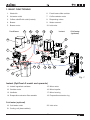
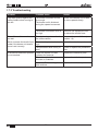
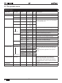
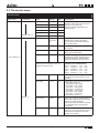
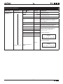
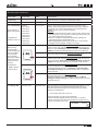
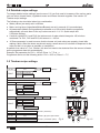
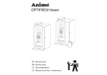
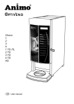
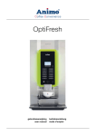
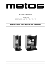
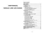
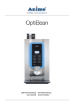
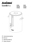
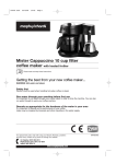
NL
Service boek
GB
Service book
D
Servicehandbuch
F
Manuel de service / maintenance
CONTENT
PREFACE .....................................................................................................................................44
1. BASIC FUNCTIONING ..........................................................................................................45
1.1 Boiler System...................................................................................................................46
1.2 Temperature regulation ....................................................................................................46
1.3 Hot water dispensing .......................................................................................................46
1.4 Cold water dispensing (optional) .....................................................................................46
1.5 Ingredients and mixer system ..........................................................................................46
1.6 Evaporation extractor system ..........................................................................................47
1.7 Brewer unit.......................................................................................................................47
1.7.1 Adjustment.............................................................................................................48
1.7.2 Setting tips .............................................................................................................49
1.7.3 Troubleshooting .....................................................................................................50
2. MENU STRUCTURE .............................................................................................................51
2.1 The operator/service menu ..............................................................................................51
2.2 The operator menu ..........................................................................................................52
2.3 The service menu ............................................................................................................53
3. RECIPE SETTINGS ...............................................................................................................61
3.1 Quick recipe .....................................................................................................................61
3.2 Model code system ..........................................................................................................61
3.3 Button settings .................................................................................................................62
3.3.1 Standard canister configuration ..............................................................................62
3.3.2 Different canister configuration ...............................................................................63
3.4 Detailed recipe settings ....................................................................................................62
3.5 Timebar recipe settings....................................................................................................62
3.6 Calibrating the hot water valves.......................................................................................64
4. SOFTWARE ..........................................................................................................................65
4.1 Memory card ....................................................................................................................65
4.2 Installing software ............................................................................................................65
4.3 Installing a language ........................................................................................................65
5. SERVICE
..........................................................................................................................96
5.1 Setting a service parameter .............................................................................................66
5.2 Preventative maintenance ...............................................................................................66
5.2.1 Service contracts ...................................................................................................66
5.2.2 Servicing ................................................................................................................67
5.3 Descaling instructions ......................................................................................................68
42
05/2008 Rev. 0.6
6. COMPONENT ACCESSIBILITY ............................................................................................70
6.1 Electronics summary .......................................................................................................71
6.1.1 Control unit ............................................................................................................71
6.1.2 Interface / Display ..................................................................................................72
6.1.3 Power supply .........................................................................................................72
6.2 Main circuit board entrances............................................................................................73
6.3 Main circuit board exits ....................................................................................................74
6.4 Main circuit board communication ...................................................................................75
7. TROUBLESHOOTING ...........................................................................................................75
7.1 Read log ..........................................................................................................................75
7.2 Clear log ..........................................................................................................................75
7.3 Troubleshooting ...............................................................................................................76
8. COIN MECHANISM (OPTIONAL)..........................................................................................78
8.1 Standard configuration.....................................................................................................78
8.2 Rejecting coins ................................................................................................................78
8.3 Activating existing tokens ................................................................................................79
8.4 Programming a new token ...............................................................................................79
8.5 Accepting Euros and Tokens ...........................................................................................79
8.6 accepting Tokens only .....................................................................................................80
8.7 Cleaning the coin holder ..................................................................................................80
05/2008 Rev. 0.6
43
© 2008 Animo®
All rights reserved.
No part of this document may be reproduced and/or made public in print, microfilm, electronic media
or any other form without the manufacturer’s prior consent. This also applies to the corresponding
diagrams and/or charts.
PREFACE
Purpose of this document
This document provides directions for use and serves as a service document for trained, authorised
service staff to safety install, programme and maintain this device.
-
Trained, authorised service staff are considered to be those who install, programme and maintain
the device, and are able to carry out repairs.
The majority of settings, including product settings, are protected by a PIN code. This PIN code
ensures that users do not gain access to the service menu. It is recommended not to leave this
document with the user after installation and to change the standard factory PIN code.
All sections and paragraphs are numbered. The various figures referred to in the text can be found in
the figures section at the beginning of the manual or with the corresponding subjects.
Pictograms and symbols.
CAUTION
General indication for: IMPORTANT, CAUTION or REMARK.
WARNING
Warning for possible damage to the device, surroundings or environment.
DANGER
Danger of possible severe damage to the device or physical injury.
DANGER
Danger of electricity and voltage.
DANGER
Danger of electrostatic discharge (ESD) in electronics.
44
05/2008 Rev. 0.6
1. BASIC FUNCTIONING
1. Waste bin
6. Fresh brew coffee canister
2. Hot water outlet
7. Coffee canister motor
3. Coffee outlet/Drink outlet (instant)
8. Dispensing valves
4. Brewer
9. Water reservoir
5. Brewer motor
10. Inlet valve
Fresh brew
7
8
9
10
11
Instant
Cold water
(optional)
12
6
13
5
14
4
20
21
19 18
16
17
15
3
2
1
Fig. 1
Instant (OptiFresh 2 model and upwards)
11. Instant ingredient canisters
15. Mixer motor
12. Canister motor
16. Mixer impellor
13. Ventilator
17. Mixer housing
14. Evaporation extractor filter cassette
18. Evaporation extractor ring
Cold water (optional)
19. Cold water outlet
22. Inlet valve
21. Cooling unit (base cabinet)
05/2008 Rev. 0.6
45
1.1 Boiler System
Turn on the device using the ON/OFF switch. The display will light up.
The magnetic valve (fig. 1-10) will open and the hot water reservoir (fig. 1-9) will be filled to the
maximum electrode. The heating element will be switched on. The display shows [ boiler filling ] and
[ boiler heating ]. As soon as the NTC sensor measures the set temperature, the heating element will
be switched off.
When a drink is being dispensed the water level drops and the maximum electrode is released;
the inlet valve (2.5 litres/min.) opens and immediately refills the reservoir until the maximum level
is reached again. If the water level falls under the minimum electrode level during operation, the
operating panel display will show [refilling boiler]. If the supply of water is not restored within 90
seconds, the display will show the error message [E3 level error] and shut off the inlet valve.
1.2 Temperature regulation
The heating element is turned on when the water temperature falls below the temperature setting and
the minimum electrode registers water. The temperature in the water reservoir is measured using an
NTC precision sensor mounted on the outside wall of the reservoir.
The water temperature also drops when drinks are dispensed. To avoid the temperature regulator from
responding too late, the heating element is switched on as soon as the inlet valve (fig. 1-10) opens
and cold water is added. The heating element switches off again as soon as the inlet valve shuts
off. The software can also be used to delay when the heating element switches off. See menu item
2.4 Settings / Temperature in the service menu. The heating element always switches off when the
maximum boiler temperature of 97˚C is reached.
1.3 Hot water dispensing
When dispensing drinks one of the dispensing valve (fig. 1-8) opens and hot water flows to the brewer
or mixer system. The flow velocity for each valve is set using the adjustment screw on the valve. The
amount of outflow is determined by the length of time that the valve stays open. In order to rinse the
brewer unit and mixer system, a small amount of rinsing water is released shortly after dispensing to
rinse away any ingredient residue.
1.4 Cold water dispensing (optional)
OptiFresh has a built-in cold water option + special base cabinet with built-in cooling unit. When
dispensing a cold-water recipe, inlet valve DV6 opens (fig. 1-21) and allows water to flow from the
mains to the cooling unit cooling coil (fig.1-20). The cooled water already present flows directly to
the cold water outlet (fig. 1-19). As soon as the valve shuts off again the cold water dispenser stops
immediately.
1.5 Ingredients and mixer system
The ingredients canisters (fig. 1-11) are powered by a 130RPM motor (fig. 1-12). The instant product
(ingredient) is forced out of the canister by a coil and drops through the dispensing bent pipes into the
mixer unit (fig. 1-17). At the same time, the dispensing valves (fig. 1-18) dispense hot water into the
mixer unit. The mixer motor (fig. 1-15) blends the instant product with water at a speed of 10,700 RPM
using the mixer rotor (fig. 1-16). The drink flows into the cup via the drink outlet (fig. 1-3). All individual
parts mentioned in this section can be sequentially coordinated using adjustable
parameters (timers) in the control unit.
46
05/2008 Rev. 0.6
1.6 Evaporation extractor system
Evaporation released during mixing is largely absorbed by the evaporation extractor ring (fig. 1-18)
and sucked into the machine via the filter cassette (fig. 1-14). The evaporation and ingredient residue
are absorbed by the filter. The filter (fig. 1-14) can be easily reached (for cleaning purposes) by
dismantling the mixer unit (fig. 1-17). To a large extent, this prevents evaporation from entering the
canister outlet and making ingredients damp.
1.7 Brewer unit
Ground coffee and hot water are dispensed to the permanent filter and are drawn into the filter by
vacuum. After making a fresh brew drink selection the following process (fig. 2) starts:
Start
position
Brewer in resting position.
Start
brewer 3
The piston moves down and sucks
the coffee extract through the
permanent filter.
Start
brewer 1
The piston leaves the resting position. Ground coffee and hot water is
dispensed to the brewer unit.
Pause 3
Just before the coffee extract
leaves the brewer the piston either
pauses or stops again to make
sure the coffee residue is sufficiently dry.
Pause 1
The piston stops just above the
outlet. Coffee and hot water is still
dispensed.
Start
brewer 4
The piston moves down further so
that the outlet opening opens.
Start
brewer 2
The piston rises and forces air
upwards out of the cylinder, ensuring that coffee and water are mixed
thoroughly. Water dispensing stops
during this cycle.
Pause 4
The coffee is now dispensed to the
cup, goblet or jug.
Pause 2
Piston stops at the highest setting to
enable the coffee to be extracted.
Return to
start
The piston returns to the start
position again. At the same time
the coffee residue is wiped away
by the filter wiper, before it drops
into the waste bin.
1,3 sec.
6,2 sec.
start
position
Start 1
1 sec.
3,8 sec.
2,5 sec.
retrun to start
Pauze 4
Pauze 3
Pauze 2
3,5 sec.
6 sec.
Start 4
Start 3
Start 2
Pauze 1
3 sec.
4 sec.
2 sec.
Fig. 2
05/2008 Rev. 0.6
47
1.7.1 Adjustment
If a leak occurs between the brewer unit and the
permanent filter the tensile force of the brewer needs to
be increased.
The tensile force of the brewer should be set so that no
water is able to leak between the brewer unit (fig. 3-1)
and the permanent filter (fig. 3-3).
The tensile force also ensures that the wiper (fig.
3-4) completely pushes the coffee residue off of the
permanent filter.
1
See figure 3 for the most important brewer parts:
2
1.
Brewer unit
2.
Rubber seal
(Art. No. 03375)
3.
Permanent filter
(Art. No. 03374)
4.
Wiper
(Art. No. 03380)
5.
Tension member
6.
Adjustment shim*
7.
Rubber
8.
H-frame
9.
Tension member adjustment
3
4
(Art. No. 03384)
5
6
1. First remove the brewer from the device (see section
8.7.2 for instructions).
2. The tensile force can be set by adding adjustment
shims (fig. 3-6) between the tension member (fig.
3-5) and the H-frame (fig. 3-8).
3. Press the H-frame downwards and take the tension
member out of the recess. Place an adjustment
shim* in the recess and replace the tension member.
CAUTION: adding multiple shims at the same time
can cause excess tensile force and damage the
brewer!
7
8
9
4. In most cases this procedure is sufficient for
repairing leaks. If the brewer unit still leaks fit
another adjustment shim.
5. If the brewer unit still leaks remove the two
adjustment shims and then turn in the tension
member once (clockwise). CAUTION: turning in the
tension member should only be done as a last
resort.
Fig. 3
* a extra shim is located behind
the stainless steel panel on the
inside of the door.
6. If the tensile force is correct but the brewer still leaks
do not increase the tensile force any more! For
further help see chapter 1.7.3 Troubleshooting.
48
05/2008 Rev. 0.6
1.7.2 Setting tips
Tensile force too low (fig. 4)
Tensile force correct (fig. 5)
Tensile force too high (fig. 6)
If the wiper moves over the
upper side of the cylinder it
makes no
If the brewer is adjusted
correctly, the wiper moves
carefully over the upper side
of the cylinder and pushes
the coffee residue off of the
permanent filter. The wiper
bends slightly.
If the brewer is adjusted too
high, the wiper will stretch
and become clearly warped.
Glancing along the long side of
the wiper will show a warped
effect in the rubber.
When the wiper moves to
the right the coffee residue is
transported to the waste bin.
The coffee residue drops from
the right side of the brewer
straight into the waste bin.
The brewer is under extreme
pressure and the sound of the
brewer motor audibly changes
as a sign of the severe load.
This may even damage the
wiper!
Fig. 5
Fig. 6
contact with the permanent
filter, so that coffee residue is
left on the filter. The wiper does
not bend at all.
If the brewer unit is adjusted in
this way it can leak. If leakage
is severe
this can even result in a
vacuum loss, which means
that the coffee residue remains
too wet (particularly for larger
dispensing volumes).
Fig. 4
During the complete brewer
cycle, ball bearings from the
wiper arms and the tension
member are under severe
pressure, resulting in bending.
The ball bearings may then
break away, cracking the plastic
brewer housing.
Signs that the tensile force is too high (fig. 6):
• The wiper is severely bent when it slides across the upper side of the brewer cylinder and
permanent filter.
• It appears as if the wiper arm is flattened between the brewer unit and the upper side of the
brewer cylinder.
• The brewer motor sounds as though it is running under extreme pressure.
• The wiper pushes against the coffee residue when moving to the left.
• Accumulation of coffee residue round the waste bin.
05/2008 Rev. 0.6
49
1.7.3 Troubleshooting
Problem
Probable cause
Action
The wiper pushes against the
coffee residue when moving to
the left.
The brewer unit does not rise
far enough.
Check if the brewer unit is able
to move upwards freely.
The brewer unit is hindered
during the upward movement.
The brewer unit tensile force is
too high.
Remove one adjustment shim
to reduce the tensile force.
The coffee residue remains
too wet.
There is inadequate suction in
the coffee residue.
Increase the pause 3 time (see
section 1.6)
Never increase the tensile force
under if the brewer unit tensile
force is set correctly.
The water temperature is too
high.
Lower the water temperature.
The permanent filter is dirty or
worn.
Clean or replace the permanent
filter.
If the above-mentioned problem
is not resolved:
Check the brewer unit and
cylinders for fractures.
Replace the defective parts.
Check the cylinder for wear
and tear or scratches.
Replace the defective parts.
Check the Teflon coating for
wear and tear.
Replace the defective parts.
50
05/2008 Rev. 0.6
2. MENU STRUCTURE
2.1 The operator/service menu
The majority of settings, including product settings, are protected by a PIN code. This PIN code
ensures that users do not gain access to the service menu.
It is recommended not to leave this document with the user after installation and to change the
standard factory PIN code.
This section describes how the various settings can be changed by trained, authorized service staff.
You can read about how to gain access to the service menu below. On access to the service menu
the control panel has the following functions:
Escape (return without making any changes)
Previous (menu item / increase value)
Next (menu item / decrease value)
Enter (accept menu option)
Summary:
05/2008 Rev. 0.6
Operator menu
Service menu
1.0
Free dispensing
2.1
Quick recipe
1.1
Clock
2.2
Button settings
1.2
Timer settings
2.3
Recipe settings
1.3
Recipe counters
2.4
Settings
1.4
Quick recipe
2.5
Reset counters
1.5
Permanent filter
2.6
Descale / filter
1.6
Software
2.7
Hardware test
1.7
PIN-code
2.8
Read log
2.9
Clear log
2.10
Load defaults
2.11
SD menu
2.12
Change PIN code
2.13
Additional settings
51
Fig. 7
2.2 The operator menu
Operator menu
Main item
Sub item
Item
1.0 Free dispensing
1.1 Clock
1.2 Timer
1.3 Recipe counters
Range
Set
Description
Yes/no
Yes
Set the device to free or paid dispensing here.
Time
HH:MM
Set the clock to the correct local time here.
Date
DD-MM-JJJJ
Set the clock to the correct local time here.
Mon-Fri
On
Off
00:00
00:00
Sat
On
Off
00:00
00:00
Set the time when the device should operate here. If
the timer switches off the device it will automatically
revert to standby mode.
Sun
On
Off
00:00
00:00
Total
Off
00:00
Free
Cups
Number of free dispensed drinks (recipe 1)
Paid
Cups
Number of paid dispensed drinks (recipe 1)
Jug
Cups
Number of dispensed jugs (recipe 1)
Total
Cups
Total counter for all dispensed recipes
Free
Cups
Total counter for all free dispensed recipes
Paid
Cups
Total counter for all paid dispensed recipes
Jug
Cups
Total counter for all dispensed jugs
Recipe 1
Recipe 12
Recipes total
Rinse counters
Total counter for recipe 1 (free-paid-jugs)
Brewer
Number of brewer rinses
Mixer(s)
Number of mixer rinses
Reset counters
1.4 Quick recipe
Recipe name 1
Recipe name 12
1.5 Permanent filter
Total rest of all counters
Cup volume
50-200 ml
120ml
Coffee (1)
-20 / +20%
0%
Decaf (2)
-20 / +20%
0%
Chocolate (3)
-20 / +20%
0%
Topping (4)
-20 / +20%
0%
Sugar (5)
-20 / +20%
0%
Reset teller
After the permanent filter of the vending unit
(brewer) has reached the maximum number of
brews the filter must be replaced. After replacing
the permanent filter, reset the ‘replace brewer filter’
indicator.
1.6 Software
1.7 PIN-code
Use this for setting the volume and strength of coffee, milk, sugar and cocoa easily per recipe (drink
button).
Only the ingredients applicable to the recipe are
shown.
Software version is readable here.
2-2-2-2-2
52
PIN code = press the number 2 key five times.
05/2008 Rev. 0.6
2.3 The service menu
Service menu
Main item
Sub item
Item
Range
Set
Description
2.1 Quick recipe
Recipe name 1
Cup volume
50-200 ml
120ml
Coffee (1)
-20 / +20%
0%
Decaf (2)
-20 / +20%
0%
Use this for setting the volume and
strength of coffee, milk, sugar and cocoa
easily per recipe (drink key).
Only the ingredients applicable to the
recipe are shown.
Chocolate (3)
-20 / +20%
0%
Topping (4)
-20 / +20%
0%
Sugar (5)
-20 / +20%
0%
<Recipe name>
Recipe list
See section
3.2
Recipe active
Yes/no
Yes
Use this to place the product concerned
out of service.
Price
0,05-2,00
0,10
For paid dispensing a price can be set
here for each product button.
Cup volume
50-230ml *
120ml
Set the desired cup volume here. All other
parameters (e.g. coffee dosage) can be
adjusted automatically. This parameter is
coupled to the quick recipe cup volume!
Recipe name 12
2.2 Button setting
Button 1
Change any recipe buttons here that
standard factory settings. All settings
that correspond to selected recipes are
automatically loaded.
* From software 2.0
Cup volume >200ml advice: deactivate
Quick recipe in the Operator menu; 2.4
Settings / I/O Quick recipe.
Cup volume >200ml change brewer
parameters (from software V02.01):
Pause 2 increase to 4,5 s. (2,5)
Start 3
increase to 4,8 s. (4,0)
Pause 3 increase to 5,5 s. (1,5)
Start 4
decrease to 2,2 s. (3,0)
Pause 4 increase to 4,0 s. (2,0)
Multicup
0-20
0
Set the number of cups that should be
dispensed when the key switch is in the
jug setting.
Key switch
0-1-2-3
0/1
Recipe button concerned works as follows:
0= key switch setting n/a
CUP (paid) or JUG* (paid)
1= key switch |: CUP (paid)
key switch –: JUG* (paid)
2= key switch |: no dispensing
key switch –: JUG* (paid)
3= key switch |: CUP (paid)
key switch –: JUG* (free)
(*when multicup is set to >1)
Push & Hold
Yes-No
No
If set to yes: pressing this button starts the
hot/cold water dispensing and releasing it
stops the hot water dispensing.
Only use this option for Water 4 and Water
6 in combination with a hot/cold water
recipe button.
Drip time
0-10 sec.
2 sec.
The length of time that the product
continues to run from the brewer or mixer.
After this time has elapsed a new drink
selection can be made.
Button 12
05/2008 Rev. 0.6
53
Service menu continued ….
Main item
Sub item
Sub
Item
Range
Description
2.3 Recipe setting
Recipe name 1
Unit 1
DV 1 WT
0,0-30,0 s
Waiting time Water 1
DV 1
0,0-100,0 ml
Dispensing amount Water 1 (Brewer)
Rinse 1 WT
0,0-20,0 s
Waiting time Rinsing Water 1
Rinse 1
0,0-15,0 ml
Dispensing amount Rinsing Water 1 Automatically deducted from Water 1
Ingredient 1 WT
0,0-30,0 s
Waiting time Ingredient 1
Ingredient 1
0,0-50,0 s
Product dispensing time Ingredient 1
Ingredient 2 WT
0,0-30,0 s
Waiting time Ingredient 2
Ingredient 2
0,0-50,0 s
Product dispensing time Ingredient 2
Start brewer
0,0-30,0 s
1st start time brewer
Pause 1 brewer
0,0-30,0 s
1st pause time brewer
Start 2 brewer
0,0-30,0 s
2nd start time brewer
Pause 2 brewer
0,0-30,0 s
2nd pause time brewer
Start 3 brewer
0,0-30,0 s
3rd start time brewer
Pause 3 brewer
0,0-30,0 s
3rd pause time brewer
Start 4 brewer
0,0-30,0 s
4th start time brewer
Pause 4 brewer
0,0-30,0 s
4th pause time brewer
DV 2 WT
0,0-30,0 s
Waiting time Water 2
DV 2
0,0-100,0 ml
Dispensing amount Water 2
Rinse 2 WT
0,0-20,0 s
Waiting time Rinsing Water 2
Rinse 2
0,0-15,0 ml
Dispensing amount Rinsing Water 2 Automatically deducted from Water 2
Ingredient 3 WT
0,0-30,0 s
Waiting time Ingredient 3
Ingredient 3
0,0-50,0 s
Product dispensing time Ingredient 3
Ingredient 4 WT
0,0-30,0 s
Waiting time Ingredient 4
Ingredient 4
0,0-50,0 s
Product dispensing time Ingredient 4
Mixer 2 WT
0,0-30,0 s
Waiting time Mixer 2
Mixer 2
0,0-50,0 s
Mixing time Mixer 2
DV 3 WT
0,0-30,0 s
Waiting time Water 3
DV 3
0-100 ml
Dispensing amount Water 3
Rinse 3 WT
0,0-20,0 s
Waiting time Rinsing Water 3
Rinse 3
0,0-15,0 ml
Dispensing time Rinsing Water 3
Automatically deducted from Water 3
Ingredient 5 WT
0,0-30,0 s
Waiting time Ingredient 5
Ingredient 5
0,0-50,0 s
Product dispensing time Ingredient 5
Ingredient 6 WT
0,0-30,0 s
Waiting time Ingredient 6 (optional)
Ingredient 6
0,0-50,0 s
Product dispensing time Ingredient 6
(optional)
Mixer 3 WT
0,0-30,0 s
Waiting time Mixer 3
Mixer 3
0,0-50,0 s
Mixing time Mixer 3
Unit 2
Unit 3
Recipe name 12
54
05/2008 Rev. 0.6
Service menu continued ….
Main item
Sub item
Sub
2.3 Recipe setting
(continued…)
Recipe name 1
Item
Range
Description
DV 4 WT
0,0-30,0 s
Waiting time Water 4
DV 4
0,0-100,0 ml
Dispensing amount Water 4
(Hot water dispensed)
DV 5 WT
0,0-30,0 s
Waiting time Water 5
DV 5
0,0-100,0 ml
Dispensing amount from an extra hot water
valve Water 5 (reserved for a Brewer
By-Pass option).
DV 6 WT
0,0-30,0 s
Waiting time Water 6
DV 6
0,0-100,0 ml
Dispensing amount from an extra inlet
valve Water 6 (Cold Water option)
Strength Coffee
0-50%
Strength Decaf
0-50%
Strength Chocolate
0-50%
Strength Topping
0-50%
Strength Sugar
0-50%
Use the strength setting item to add an
ingredient to the strength adjustment.
Ingredient strength adjustment:
0= off / > 1 = on
Example: [coffee] 20%
Strength
-0
+
++
-20% -10% 0 10% 20%
Example: [cocoa] 40%
0-50%
Recipe name 12
05/2008 Rev. 0.6
Strength
-0
+
++
-40% -20% 0 20% 40%
Strength Ingrediënt 6
Option
55
Service menu continued…
Main item
Sub item
Item
2.4 Settings
Language
English
Range
Setting
Description
Language choice display.
Ex factory setting English.
Dutch
German
French
Temperature
Temp. boiler
95°C *
Boiler temperature standard model
1A - 5A
90°C *
Boiler temperature FreshBrew +
instant model 6A t/m 9A
70-97°C *
* From software 2.0
Hysteresis
0-10°C
2°C
Temperature drop, after which boiler
must reheat
Output block
70-95°C
78°C
Boiler temperature disables dispensing. Display: [Out of order, boiler
heating]
Output release
70-95°C
85°C
Boiler temperature allows dispensing again
Stand-by
60-95°C
60°C
Boiler temperature during stand-by
Extended Heating
0-5 sec
1 sec
To maintain the optimum boiler temperature the heating element and
inlet valve switch on simultaneously.
Set the waste delay of the element
here after the inlet valve is closed.
Inlet valve
Heating
Inlet valve
Heating
Display
Show clock
Yes/no
No
Show clock in display
Show date
Yes/no
No
Show date in display
Yes/no
No
Show message text (running text) in
display. Only shown if Display Date,
Clock or both are set to no. Message text only programmable using
a future PC programme.
Use bleeper
Yes/no
Yes
Sound signal on or off
Fan time
0-300 sec.
60 s.
Duration of Fan speed 1 after
dispensing
Fan speed 1
40-100%
50%
Fan speed when resting
Fan speed 2
70-100%
100%
Fan speed during dispensing
Message text
56
05/2008 Rev. 0.6
Service menu continued …..
Main item
Sub item
Item
2.4 Settings
(continued…)
Coin system
G13
Range
Setting
0-100,00 +
Token
€ 0,05
€ 0,10
€ 0,20
€ 0,50
€ 1,00
€ 2,00
Single vend
ja-nee
ja
Yes: any excess credit is not
retained for next drink. No: credit
retained for next drink.
Max coin accep.
€ 0,05100,00
€ 1,00
Coins larger than € 1.00 are rejected
and ejected through the return slot
of the coin mechanism. Adjust to the
highest recipe product price.
Point position
0-2
2
Decimal position in amount
Show credit
Yes/no
Yes
Show credit on the display
Coin channel 1
Coin channel 6
MDB
I/0 Reset counter
I/0 Quick recipe
* From software 2.0
* Drip tray sign.
2.5 Reset counters
Rinse counters
Recipe counters
Description
Coin value setting for each channel.
€0.05-€2 respectively.
0.00=free
TOKEN=coffee token
No MDB software available yet
Yes/no
No
Add Reset counters menu item to
the operator menu
Yes/no
Yes
Add Quick recipe menu item to the
operator menu
Yes/no
Yes
Turns off drip tray sensor software.
Brewer counter?
Reset brewer spoelteller
Mixer counter?
Reset mixer spoelteller
Recipe counter 1
Reset recepttellers per recept.
Recipe counter 12
Reset counter total
Reset totaal tellers
Reset all counters
2.6 Descale/filter
Service moment
Reset alle tellers ineens
0-25000
Service counter
Reset serv. coun
05/2008 Rev. 0.6
12500
After the Service Due setting has
been reached the Descale/filter
indicator will be displayed. See section 5. Service
?????
The number of beverages dispensed is counted here. Check here
to see how far the machine is from
periodic maintenance (descaling
boiler or replacing water filter).
After periodic maintenance has
been carried out (boiler descaled or
filter replaced) the service counter
should be set to nil.
57
Service menu continued….
Main item
Sub item
Sub
Range
Description
2.7 Hardware test
Inputs
Temperature
Boiler temp
Level sensors
High
Low
Yes/no
Yes/no
Drip tray sensor
Yes/no
Waste bin
Yes/no
Door switch
Yes/no
Brewer switch
Yes/no
Key switch
Yes/no
Shows the status of the sensors/switches
indicated
Outputs
KW1
Inlet valve (Boiler)
Test by holding
in recipe button
11.
DV1
Dispenser valve 1 (Brewer)
DV2
Dispenser valve 2 (Mixer 2)
DV3
# During test the
display shows
the Nominal
current (mA)
When the
Nominal current
of a output rises
above the set
current *
mentioned output
will be shut off.
Caution: BM 1
goes through a
complete drinks
cycle.
* 400 mA
Dispenser valve 3 (Mixer 3)
DV4
Dispenser valve 4 (Hot water)
DV5
Dispenser valve 5 (n/a)
DV6
Inlet valve 6 (Cold water) optional!
IM1 #
Ingredients motor 1 (Canister 1)
IM2 #
Ingredients motor 2 (Canister 2)
IM3 #
Ingredients motor 3 (Canister 3)
* 400 mA
IM4 #
Ingredients motor 4 (Canister 4)
IM5 #
Ingredients motor 5 (Canister 5)
IM6 #
Ingredients motor 6 (Canister 6)
BM/MM1 #
Brewer motor
MM2 #
* 800 mA
MM3 #
Mixer motor 2
Mixer motor 3
Ventilator
* 200 mA
LED’s
Ventilator
LED’s
Calib. valves
DV1
15 ml / sec
Calibrate to 150 ml (10 sec x 15 ml)
Test by holding
in recipe button
11 (for 1 sec.)
to open the relevant valve for
10 seconds.
DV2
15 ml / sec
Calibrate to 150 ml (10 sec x 15 ml)
DV3
15 ml / sec
Calibrate to 150 ml (10 sec x 15 ml)
DV4
20 ml / sec
Calibrate to 200 ml (10 sec x 20 ml)
DV5
20ml / sec.
Calibrate to 200ml (10sec. x 20ml)
(Optional valve for Brewer By-pass)
DV6
42 ml / sec
Inlet valve cannot be calibrated (fixed flow)
58
05/2008 Rev. 0.6
Service menu continued….
Main item
Sub item
Item
2.8 Read log
Description
Saves last 20 error messages, including date and time
2.9 Clear log
Are you sure?
2.10 Load defaults
Model #
OF1A xx00
OF2A xx00
OF3A xx00
OF4A xx00
OF5A xx00 *
OF6A xx00 *
OF7A xx00 *
OF8A xx00 *
OF9A xx00 *
Are you sure?
When a new circuit board is introduced it is necessary to load
defaults. When loading defaults it must be stated on the OptiFresh
model plate. The correct model settings are not loaded until the
question ‘Are you sure?’ has been confirmed.
Attention:
● Before you start changing the button- and/or receipt- settings, first
close the service menu, only after re-entering the service menu the
new model settings will be activated.
● When you confirm this setting all loaded factory settings and
changed programmed values will be lost.
● After loading defaults the PIN code reverts to 2-2-2-2-2 and the
language reverts to English. Change if necessary.
Load data
Pers. settings
This menu item is for loading personal settings to the device using
an SD memory card. This file contains the (amended) personal settings for menus: 2.4 Settings / 2/6 Descale-filter / 2.13 Additional
settings. The data file (Ofxxxx00.mdu) should be on the SD card.
Language
This menu item is for loading a different language set to the
device. The data file (xxxxxx.tlf) should be on the SD card.
Recipe
This menu item is for loading personal recipes to the device using
an SD memory card. This file contains the (amended) personal recipes for menus: 2.1 Quick recipe / 2.2 Button settings / 2.3 Recipe
settings. The data file (OFxxxx00.rcu) should be on the SD card.
Pers. settings
This menu item is for saving personal settings to an SD memory
card and copying them to another device.
All settings amended in menus: 2.4 Settings / 2.6 Descale-filter /
2.13 Additional settings are loaded to the SD card in one data file
(OFxxxx00.mdu).
Recipes
This menu item is for saving personal recipes to an SD memory
card and copying them to another device.
All settings amended in menus: 2.1 Quick recipe / 2.2 Button
settings/ 2.3 Recipe settings are loaded to the SD card in one data
file (OFxxxx00.rcu).
Repeat PIN code
This menu item is for changing the PIN code using buttons 1-4 only.
The entire service menu is accessed with this PIN code, which
prevents unintentional changes from being made to the machine
settings by untrained staff.
# See chapter 3.2
Model code system
* available from
software version 2.0
2.11 SD menu
Before saving
or loading data,
insert an empty SD
memory card into
the card reader .
Memory Card
This is located
behind the stainless
steel panel on the
inside of the door.
SD card
specifications:
Clears log
Save data
- 16MB or greater
- FAT16 format
Memory Card
2.12 Change PIN
New PIN code
•
The ex-factory PIN code is 2-2-2-2-2
PIN code forgotten or needs to be deactivated?
The PIN code input display (operator menu item 1.7) shows a
number on the right. Enter the corresponding PIN code (see list on
p.60) to access the service menu.
05/2008 Rev. 0.6
59
Service menu continued…
Main item
Sub item
2.13 Addit. settings
Waste manag.
From software 2.0
moved to menu
2.4.10
Item
Range
Cup amount
0-1000
250
Almost full sign.
0-1000
230
After reaching the set total of brewer movements, the display reads: Waste bin almost
full
Time-out reset
0-50 sec.
15 s
The length of time that the waste bin is allowed to be removed (for emptying). When
replacing it the (internal) waste bin counter is
reset. Any display messages disappear.
Waste bin sign..
Yes/no
Yes
Turns off waste bin sensor software (bypass).
Yes/no
Yes
Turns off drip tray sensor software.
Cycle counter
xxxxx
0-99999
This Cycle counter records the number of
vends the brewer has made. Tip: This counter
can be reset after maintenance if the brewer
has been checked.
Reset counter?
Perm.filter coun
Reset p. filter
Description
After reaching the set total of brewer
movements, dispensing is disabled and
the display reads: Out of order – Waste
bin full
Drip tray sign.
Reset c. counter
Set
xxxxx
Reset Cycle counter (Brewer)
0-10.000
6000
When the set number of (Brewer) vends is
reached the display reads ‘Replace permanent filter’ when switching on.
Reset counter?
PIN Code Table
Reset the permanent filter counter after
(preventative) replacement
No.
Table 1
Pincode
Table 2
Pincode
1
3
4
2
4
2
11
1
3
3
3
2
2
3
1
4
3
4
12
1
2
4
1
3
3
4
1
3
4
3
13
4
3
1
2
1
4
4
3
2
3
2
14
1
1
1
4
2
5
2
3
3
4
1
15
2
1
2
1
1
6
4
2
1
3
1
16
1
2
2
3
3
7
2
4
2
4
4
17
3
4
1
4
4
8
2
3
2
4
1
18
4
1
4
3
3
9
2
4
3
2
3
19
3
1
2
4
1
10
3
1
3
3
2
20
2
2
3
2
4
Water
Quality
Water Hardness Table
No.
Hardness
Limescale
Indicator ...cups
°D
°F
mmol/l
mgCaCo3/l
Very hard
18-30
32-55
3,2-5,3
321- 536
5000
Hard
12-18
22-32
2,2-3,2
214-321
8500
Average
8-12
15-22
1,4-2,2
268-214
12.500*
Soft
4-8
7-15
0,7-1,4
72-268
20.500
Very soft
0-4
0-7
0- 0,7
0-72
0 = off
60
05/2008 Rev. 0.6
3. RECIPE SETTINGS
3.1 Quick recipe
First of all we would like to remind you that the cup volume (ml) and strength (%) can easily be set in
the service menu 2.1 Quick recipe (page 53 of this document).
The operator of the device (end user) also has access to this quick recipe, which is found under
section 1.4 Quick recipe (see user manual). As supplier of the device, you can remove the quick recipe
from the operator menu if desired. Go to 2.4 Settings / 2.4.9 I/0 Quick recipe via the service menu
and change Yes into No.
3.2 Model code system
The OptiFresh models have the following standard canister configurations (fig. 8):
1
1
1
3
3
1
4
3
4
5
Fig. 8
OptiFresh 1 A
OptiFresh 2 A
OptiFresh 3 A
[FB Coffee]
[FB Coffee / Chocolate]
[FB Coffee / Chocolate / Topping]
OptiFresh 4 A
[FB Coffee / Chocolate / Topping / Sugar]
If the device is delivered with a different canister configuration this can be given a new number using
the model code system below.
OptiFresh
O F 4 A aa00
Model
Internal data
OF 1 standard
1
OF 2 standard
2
OF 3 standard
3
A
Base execution
OF 4 standard
4
D
Decaf execution
OF 2 Topping instead of Chocolate
5
OF 2 Instant Coffee instead of Chocolate
6
OF 3 Instant Coffee instead of Chocolate
7
OF 3 Instant Coffee instead of Topping
8
OF 4 Instant Coffee instead of Sugar
9
05/2008 Rev. 0.6
Model version
61
3.3 Button settings
3.3.1 Standard canister configuration
The standard of programmed recipes (table 3) can easily be transferred over the 12 recipe buttons.
See service menu 2.2 Button settings (page 53).
Optional recipes
Standard recipes
The optional recipes table are already contained in the software and can easily be programmed under
one recipe button. See service menu 2.2 Button settings (page 53).
OptiFresh 1
OptiFresh 2
OptiFresh 3
OptiFresh 4
Button
Model 1 A
Model 2 A
Model 3 A
Model 4 A
1
# Coffee
# Coffee
# Coffee
# Coffee
2
Espresso
Espresso
Coffee Milk
Coffee Milk
3
Double Espresso
Double Espresso
Espresso
Sugar
4
-
Hot Chocolate
Double Espresso
Milk & Sugar
5
-
Coffee Choc
Hot Chocolate
Espresso
6
-
-
Coffee Choc
Double Espresso
7
-
-
Cappuccino
Hot Chocolate
8
-
-
Moccacino
Coffee Choc
9
-
-
-
Cappuccino
10
-
-
-
Moccacino
11
-
-
-
-
12
# Hot water
# Hot water
# Hot water
# Hot water
Cold Water *
Cold Water *
Cold Water *
Cold Water *
Jug of Coffee
Espresso Choc
Latte Macchiato
Latte Macchiato
Jug of Hot Water
Jug of Coffee
Espresso Choc
Cappuccino Sugar
Jug of Hot Water
Chocolate Milk
Espresso Choc
Warm Milk
Espresso Sugar
Café au Lait
Chocolate Milk
Jug of Coffee
Warm Milk
Jug of Hot Water
Café au Lait
Jug of Coffee
# = jug filled using key switch
Jug of Hot Water
* = only OptiFresh with cold water option
Table 3
62
05/2008 Rev. 0.6
3.3.2 Different canister configuration*
The standard of programmed recipes (table 4) can easily be transferred over the 12 recipe buttons.
See service menu 2.2 Button settings (page 53).
The optional recipes table are already contained in the software and can easily be programmed under
one recipe button. See service menu 2.2 Button settings (page 53).
* Available from software version 2.0
OptiFresh 3
OptiFresh 4
Button
Model 5 A
Model 6 A
Model 7 A
Model 8 A
Model 9 A
1
# Coffee
# Coffee
# Coffee
# Coffee
# Coffee
2
Coffee Milk
Espresso
Coffee Milk
Espresso
Coffee Milk
3
Espresso
Double Espresso
Espresso
Double Espresso
Espresso
4
Double Espresso
-
Double Espresso
Hot Chocolate
Hot Chocolate
5
Cappuccino
-
Cappuccino
Coffee Choc
Coffee Choc
6
Café au Lait
-
Café au Lait
-
Cappuccino
7
Latte Macchiato
Coffee inst.
Coffee inst.
Coffee inst.
Coffee inst.
Espresso inst.
Coffee inst. Mlk
Espresso inst.
Coffee inst. Milk
8
9
-
Dub. Espresso inst.
Espresso inst.
Dub. Espresso inst.
Espresso inst.
10
-
-
Dub. Espresso inst.
-
Moccacino inst.
11
-
-
Cappuccino inst.
-
Cappuccino inst.
12
# Hot water
# Hot water
# Hot water
# Hot water
# Hot water
Cold Water *
Cold Water *
Cold Water *
Cold Water *
Cold Water *
Warm Milk
Jug of Coffee
Latte Macchiato
Espresso Choc
Latte Macchiato
Jug of Coffee
Jug of Coffee inst.
Warm Milk
Jug of Coffee
Espresso Choc
Jug of Hot Water
Jug of Hot Water
Café au Lait inst.
Jug of Coffee inst.
Chocolate Milk
Jug of Coffee
Jug of Hot Water
Warm Milk
Optional recipes
Standard recipes
OptiFresh 2
Jug of Coffee inst.
Café au Lait
Jug of Hot Water
Moccacino
Café au Lait inst.
Latte Macchiato inst
# = jug filled using key switch
Jug of Coffee
* = only OptiFresh with cold water option
Jug of Coffee inst.
inst. = Recipe made with instant coffee
Jug of Hot Water
Table 4
05/2008 Rev. 0.6
63
3.4 Detailed recipe settings
To change detailed recipe settings (service menu 2.3) you first need to be aware of the various parts
such as valves, brewer motor, ingredients motor and mixers that work together. See section 3.5
Timebar recipe settings.
The following rules should be taken into consideration:
● Water (valves) are easily set in millilitres.
● Motor running times (Ingredients/Mixers/Brewer) are set in seconds (0.1 second steps)
● All parameters (Water and Ingredients) are based on a 100 ml drink and the programme
automatically converts them to the cup volume as set in 1.4 / 2.1 Quick recipe and
2.2 Button settings.
● If a drink contains DV1 and DV2, the total amount of water should always be 100 ml when
combined. For DV1, DV2 and DV3, this amount = > 100 ml.
●
A Rinse parameter is used to ensure that the brewer unit and mixers are properly rinsed after
making a drink. After the mixers are almost empty a small amount of hot water is dispensed to the
mixer so that it is as clean as possible on completion.
A realistic rinse value is 7.5 ml. Caution: this does not need to be deducted from the amount of water
as the programme does this automatically!
Example: Set parameter for DV1 = 100 ml, Rinse 1 = 7.5 ml -->
Programme carries out the following action: DV1 = 92.5 ml, Rinse 1 = 7.5
3.5 Timebar recipe settings
OptiFresh 1
DV 1WT
DV 1
Rinse 1 WT
Rinse 1
OptiFresh 2
15ml/sec.
Unit 2
Unit 1
Unit 1
Ingr. WT
Ingredient 1
Ingr. WT
Ingredient 2
3
1
Start1 Pause1 Start2 Pause2 Start3 Pause3 Start4 Pause4
DV 2
DV 1
DV 2 WT
Unit 2
DV 2
Rinse 2 WT
Ingr. WT
Ingredient 3
Ingr. WT
Ingredient 4
Mixer WT
Rinse 2
15ml/sec.
Brewer
Mixer 2
Hot
DV 4
Cold
DV 6
Mixer 2
OptiFresh 3
DV 3 WT
Unit 3
DV 3
Rinse 3 WT Rinse 3
Ingr. WT
Ingredient 5
Ingr. WT
Ingredient 6
15ml/sec.
OptiFresh 4
Unit 2
Unit 1
3
1
Mixer WT
Unit 3
4
5
Mixer 3
DV 1
DV 4 WT
DV 4
20ml/sec. (Hot water)
DV 5 WT
DV 5
20ml/sec. (By-pass option brewer
DV 6 WT
DV 6
42ml/sec. (Cold water option)
64
Brewer
Fig. 9
DV 2
DV 3
Mixer 2
Mixer 3
Hot
DV 4
Cold
DV 6
Fig. 10
05/2008 Rev. 0.6
3.6 Calibrating the hot water valves
The Brewer and Mixers are supplied with water by the Dispensing Valves (DV).
In the unlikely event that one of the valves needs replacing, it
should be calibrated to one of the dispensing speeds given in
figure 11 after it has been fitted.
When calibrating valves, use the special Valve Calibration
menu by opening the Service Menu and going to 2.7 Hardware Test / 2.7.2 Calibrating Valves.
The hot water dispensing valves are accessible by dismantling
the canister plateau behind the ingredients canisters.
DV 1 = 15ml/sec. (Brewer)
DV 4 = 20ml/sec. (Hot water)
DV 2 = 15ml/sec. (Mixer 2)
DV 3 = 15ml/sec. (Mixer 3)
DV 5 = 20ml/sec. (Option Brewer By-pass)
Fig. 11
4. SOFTWARE
4.1 Memory card
Type:
SD
Capacity: 16Mb or bigger
Format: FAT (no FAT32 or NTFS)
4.2 Installing software
The device can easily be installed with new software, which is made available as follows:
● www.Animo.eu / dealer log in: Extranet *
● By Email
4.3 Installing a language
The device has four standard languages (NL/GB/D/F).
The device can easily be installed with another language set (if available).
A new language file can be made available as follows:
● www.Animo.eu / dealer log in: Extranet *
● By Email
* User manuals, service manuals and software updates can be found on the Extranet section of www.
animo.eu. If you do not have access, please request your personal login code on our website.
05/2008 Rev. 0.6
65
5.0 SERVICE
WARNING
•
In order to descale the water reservoir, the device must be opened. This will expose live parts of
the machine, which can be touched easily. This may lead to highly dangerous situations!
WARNING
•
The device must not be submerged or hosed down.
•
Always stay with the device during maintenance work.
5.1 Setting a service parameter
During installation, set a parameter for the device to be
ON/OFF
serviced. See Service Menu item 2.8 Descale / filter. Use the
table below to set the correct service parameter.
Service parameter reached?
The dispensed drinks are counted during use. If the service
parameter is reached the display shows the following
message: Descale / filter (fig. 12).
The message indicates that the device must be descaled.
If a water filter is fitted (recommended), this is also an
indication that the filter must be replaced.
Water hardness table
Water
Quality
Fig. 12
Hardness
Service Indicator (cups)
°D
°F
mmol/l
mgCaCo3/l
Very hard
18-30
32-55
3,2-5,3
321- 536
5000
Hard
12-18
22-32
2,2-3,2
214-321
8500
Average
8-12
15-22
1,4-2,2
268-214
12.500*
Soft
4-8
7-15
0,7-1,4
72-268
20.500
Very soft
0-4
0-7
0- 0,7
0-72
0 = uit
Table 5
5.2 Preventative maintenance
5.2.1 Service contracts
PREFACE
Preventative maintenance will lengthen the life cycle of the device and reduce the chance of
malfunction. Before carrying out maintenance, read the safety instructions in the user manual, service
manual, and recommended cleaning agents. User manuals, service manuals and software updates
can be found on the Extranet section of www.animo.eu. If you do not have access, please request
your personal login code on our website.
66
05/2008 Rev. 0.6
Water filter
We strongly advise you to use a water softener and/or water filter if the mains water is heavily
chlorinated or is too hard. This increases the quality of the drink and will ensure that you do not have
to descale the device too often.
Brewer unit
In some cases, a substitute brewer is used during maintenance. The brewer removed can then be
repaired in the workshop before being used again during the next service.
5.2.2 Servicing
For an estimated total of < 25000 cups a year we recommend one service a year.
For an estimated total of > 25000 cups a year we recommend two services a year.
Service activity
Descale
Time
OptiFresh
1
2
3
4
Animo descaler
49007
Valve seal set
99673
2x
3x
3x
4x
Permanent filter
03374
1x
1x
1x
1x
Wiper
03380
1x
1x
1x
1x
Seals
03375
1x
1x
1x
1x
Animo cleaner
49009
Mixer fan
03254
-
1x
1x
2x
Mounting ring (incl.
seals).
03253
-
1x
1x
2x
15 min.
Replace a number of parts.
Clean the brewer.
Check that it is working correctly.
Adjust brewer unit tensile strength if
necessary.
Mixers
Art. No.:
45 min.
Descale boiler system (see service manual).
Use valve seal set if necessary.
Brewer
Product
10 min.
Check Motor axis for dirt and wear and tear.
Replace green mounting ring.
Replace mixer rotor.
Clean mixer parts.
Grease water connection using silicone grease).
Inspection (general)
Check that the entire machine is working.
Check parts for damage/wear and tear and/
or leaks.
Cleaning (general)
Brewer and mixer unit as for weekly cleaning.
The entire interior and exterior of the machine.
Table 6
05/2008 Rev. 0.6
67
WARNING
•
Do not leave the device during maintenance work.
•
When descaling always follow the instructions for
the descaler used.
•
It is advisable to wear safety goggles and protective
gloves when descaling.
•
After descaling, allow the device to run a minimum
of three times.
•
Wash hands thoroughly after descaling.
•
The device must not be submerged or hosed down.
1
5.3 Descaling instructions
Animo supplies Descaler in the following quantities:
•
Descaler 48 x 50g sachets (Art. No. : 49007)
•
Descaler 1kg tube (Art. No. 00009)
Time required, products and tools:
•
Time: approximately 45 minutes
•
Animo Descaler x 2 sachets or 8-10 dessert spoons
•
Drip tray of approximately 1.5 litres
•
Bucket or basin at hand
2
1. Switch on the device and let it warm up.
The advantage of this is that the reservoir is properly
warmed in advance, which achieves a better result
during descaling.
2. Switch off the device and pull the plug out of the
socket.
3. Dispense one litre of hot water from the water
reservoir using the tap at the front of the device
(fig. 13-1).
4. Remove the rear plate (fig. 13-2) and unscrew the
reserve lid (fig. 13-3). Take care: HOT!
5. Before going any further, read the warnings and
instructions for use on the Animo Descaler sachets
before dissolving two 50g sachets in the measuring
jug (8-10 dessert spoons).
3
.
Fig. 13
68
05/2008 Rev. 0.6
6. Pour the acid solution into the reservoir (fig. 14-1).
The acid solution will now react with the lime scale.
7. Leave the solution to soak for a minimum of 10
minutes, until the foaming has stopped.
1
8. Use a brush to spread the acid over the level
electrodes during the soaking time (fig. 14-2).
9. Put the plug in the socket again and turn on the
device so that the reservoir warms up.
2
10. Activate the BREWER cleaning programme
(fig. 14-3), so that the acid solution leaves the water
reservoir via the BREWER VALVES. Place a
drip tray under both outlets (fig. 14-4) and follow the
instructions on the display.
11. Activate the MIXER cleaning programme (fig. 14-5),
so that the acid solution leaves the water reservoir
via the MIXER VALVES. Place a drip tray under
both outlets (fig. 14-4) and follow the instructions on
the display.
3
12. Turn off the device and allow the reservoir to empty
completely using the tap (fig. 14-1).
13. Turn on the device again; the reservoir will refill with
clean water. Repeat instruction 10 one more time to
rinse the reservoir completely free of acid.
14. Turn on the device again; the reservoir will refill with
clean water. Allow the water reservoir to heat up.
15. Activate the BREWER cleaning programme
(fig. 14-3), so that valves and pipe systems are
rinsed clean. Place a drip tray under both outlets
(fig. 14-4).
4
16. Activate the MIXER programme (fig. 14-5), so that
valves and pipe systems are rinsed clean. Place the
measuring jug under the outlet (fig. 14-6).
5
17. Repeat the above descaling procedure if lime scale
is still present in the reservoir.
18. Screw the lid back onto the reservoir and replace
the rear plate.
19. Clear the service parameter counter in the Service
Menu 2.6 Descale / filter /2.6.2 Reset service
counter.
20. The device is now ready for use again.
6
Fig. 14
05/2008 Rev. 0.6
69
6. COMPONENT ACCESSIBILITY
Display
Dispensing valves
Key switch
Service panel
Ingredient motors
Circuit board
Ventilator
Brewer
Main switch
Door switch
Waste bin senso
Brewer motor
Power relay
24V power supp
Water reservoir
Level / NTC
Boil dry safety
Control unit
Drip tray full sensor
Inlet valve
Fig. 15
70
05/2008 Rev. 0.6
6.1 Electronics summary
WARNING
During repairs or maintenance work, avoid electrostatic
discharge (ESD) on the control unit.
● Control unit ........................................ 6.1.1
● Power supply 230Vac:24V 65W ........ 6.1.2
● Circuit board ...................................... 6.1.3
6.1.1 Control unit
This control unit is the device’s main control unit and
is accessible by removing the left side panel (fig. 16a).
The following important parts can be found in the main
control unit (fig. 16):
● Fuse (6, 3A t): to safeguard the power supply to the
control unit.
● Battery: to maintain the clock and counter function
when there is no power supply to the device.
CSI
G13
RS232
COMMUNICATION
MIXERS
INPUTS
GND
AS
BS
DS
INGREDIENT MOTORS
+5V
GND
LB
GND
LSL
GND
LSH
OUTPUTS
TEMP1
J16
+
KW1
KW2
KW3
DV1
DOSING VALVES
BATT
MIX/BR 18
17
MIX2 16
15
MIX3 14
13
12
IM1
11
10
IM2
9
8
IM3
7
6
IM4
5
4
IM5
3
2
IM6
1
Fig. 16a
J2
INLET
VALVES
MICROCONTROLLER
J7
1
2
MDB
USB
SENSORS
1
2
3
4
5
6
7
8
9
10
11
12
13
14
15
16
17
18
KEY / DISPLAY
1 J12
2
3
4
5
6
7
8
9
10
11
12
DV2
DV3
DV4
DV5
DV6
18
17
16
15
14
13
12
11
10
9
8
7
6
5
4
3
2
1
J4
FAN
2
1
HEATER
RELAIS
4
3
2
1
J15
F1
POWER SUPPLY
F6,3AT
+24Vdc
J1
05/2008 Rev. 0.6
24V DC
1
2
3
4
GND
J6
Fig. 16
71
6.1.2 Interface / Display
The interface (fig. 17) connects all components found
inside and on the door with the main control unit via a
flat cable.
Animo OptiFresh
JP3
DISPLAY
MAIN BOARD
J14
KEYSWITCH
JP2
Fig. 17a
TO MAIN PC BOARD
J3
SERVICE KEYBOARD
J2
C
SD-READER
J1
SD Memory Card
KEYBOARD
JP4
J4
Fig. 17
6.1.3 Power supply
The 24 V DC power supply (fig. 18) consists of a
24V DC 65W switch mode power supply and can be
accessed by removing the rear plate. The power supply
is located under the main circuit.
During an overload the power supply automatically
switches off. Reset the power supply by turning the
main switch off and on.
+24V
GND
1
Fig. 18a
Fig. 18
84-265 Vac
72
05/2008 Rev. 0.6
6.2 Main circuit board entrances
Connector J12
Connector J7
Colour
Comments
1-2
-
3
Drip tray sensor
Yellow
4
Drip tray sensor Mass
Black
5
Level sensor Low
Brown
6
Level sensor Mass
Green
7
Level sensor High
White
8
-
9
Waste bin switch
Pink
Waste bin in position;
contact closed
10
Brewer switch
Grey
Brewer in home position;
contact closed
11
Door switch
Orange
Door closed; contact
closed
12-18
-
Comments
1
2
3
4
5
6
7
8
9
10
11
12
13
14
15
16
17
18
Connector J16
Sensor
Colour
1
NTC sensor
Violet
2
NTC sensor
Violet
GND
AS
BS
DS
J7
1
2
TEMP1
Pin
+5V
GND
LB
GND
LSL
GND
LSH
INPUTS
Sensor
SENSORS
Pin
KEY / DISPLAY
1 J12
2
3
4
5
6
7
8
9
10
11
12
Connector cable between the main circuit and door circuit
J16
Battery
Lithium 3V Type CR2025
Art. No. 02816
BATT
+
Fuse
6,3A slow
Art. No. 03391
F1
F6,3AT
Connector J1
Pin
Colour
Mass (GND)
Black
2
Mass (GND)
Black
3
+24V DC
Red
4
+24V DC
Red
05/2008 Rev. 0.6
1
2
3
4
24V DC
1
Comments
J1
Fig. 19
73
6.3 Main circuit board exits
Connector J2
Motor
Colour
Comments
17-18
Brewer / Mixer 1
Black
Correct direction of rotation = red wire (+24VDC)
NOT on red spot of the
Brewer Motor
15-16
Mixer 2
Violet
13-14
Mixer 3
Pink
11-12
Ingredient Motor 1
Brown
9-10
Ingredient Motor 2
Green
7-8
Ingredient Motor 3
White
5-6
Ingredient Motor 4
Yellow
3-4
Ingredient Motor 5
Grey
1-2
Ingredient Motor 6
MIXERS
Pin
INGREDIENT MOTORS
Take care to rotate in
the right direction!
Shared +24 DC (red wire)
on red spot on Mixer and
Ingredients Motor.
-
MIX/BR 18
17
MIX2 16
15
MIX3 14
13
12
IM1
11
10
IM2
9
8
IM3
7
6
IM4
5
4
IM5
3
2
IM6
1
J2
Connector J4
17-18
KW 1 (inlet valve)
Violet
15-16
KW 2
-
13-14
KW 3
-
11-12
DV 1 (brewer valve)
Brown
9-10
DV 2 (mixer 2 valve)
White
7-8
DV 3 (mixer 3 valve)
Yellow
5-6
DV 4 (hot water tap)
Green
3-4
DV 5
Grey
1-2
DV 6 (cold water tap
-
Comments
Red wire is a shared
(24VDC) connection
-
KW1
KW2
KW3
DV1
DOSING VALVES
Colour
INLET
VALVES
Valve
OUTPUTS
Pin
DV2
DV3
DV4
DV5
DV6
18
17
16
15
14
13
12
11
10
9
8
7
6
5
4
3
2
1
Connector J15
Motor
2
J4
Colour
Comments
Red
Ventilator
1
Orange
J15
HEATER
RELAIS
Connector J6
Pin
Relay
4
2
1
FAN
Pin
Colour
Comments
H1
H2/3
4
3
2
1
J6
Red
Power relay (element)
3
White
2
Power relay
Fig. 20
-
1
74
05/2008 Rev. 0.6
6.4 Main circuit board communication
Communication
Conn
Comments
CSI
G13
Coin tester NRI G13
OPTIONAL
USB
MDB
Future port
CSI
Future port
RS232
Future port
USB
Future port
MDB
G13
RS232
COMMUNICATION
Fig. 21
7. TROUBLESHOOTING
WARNING
● When carrying out repairs and cleaning the device, the plug should always be removed from the
wall socket before the device is opened.
Preface
Before searching for the defect, check that all parts are in their correct position. To do this, remove
the device’s rear plate and check that all printed circuit boards, connectors, wire beams and pipes are
mounted correctly.
After carrying out a general parts inspection, use section 7.3 Troubleshooting analysis to verify the
probable cause of the problem.
#) If the column solution advises replacement of the part concerned, there is always the possibility
that the defect may be caused by another problem. The functioning of the device should therefore be
thoroughly tested to make sure that the defect does not reappear.
7.1 Read log
Number
Trouble code
The last 20 error messages displayed during use are
registered and saved (fig. 22).
To read out these error messages activate the menu item 2.8.
The first error is the most recent error message.
•
The first line shows the same error codes listed in
the troubleshooting analysis table (see section 7.3)
•
The second line shows the date and time at which the
error message occurred.
Date
Time
Fig. 22
7.2 Clear log
Use the Clear log function in service menu 2.9 to clear the log.
05/2008 Rev. 0.6
75
7.3 Troubleshooting
Display
messages
and errors
Possible cause
Action
When used for the first time: boiler
is still empty and is being filled.
No action required. When boiler reaches
the appropriate level, the display will show
'Boiler is heating up'.
During use: boiler is not filling
up or is filling up too slowly. After
60 sec. the display will show 'E3
Level error'.
Check the water pressure, turn the water
supply tap completely open and check the
connection tube for any kinks.
Out of order
Boiler heating
The boiler temperature is
(temporarily) too low because too
much water has been used.
Once the temperature is restored, the
message automatically disappears and the
drink selection buttons are reactivated.
Out of order
Drip tray full
Drip tray full.
Once the drip tray is emptied, the message
automatically disappears and the drink
selection buttons are reactivated.
Out of order
Waste bin full
The maximum number of coffee
cups that the waste bin can hold
has been reached.
Empty waste bin. The cup counter is
automatically reset when the waste bin is
replaced.
Out of order
Waste bin is missing
Waste bin is not detected.
Check the waste bin.
Out of order
Door open
For safety reasons, the machine
automatically switches off if the
door is opened.
The machine can be operated with the door
open by using the door pin (User manual:
section 8.1 ).
Out of order
Stand-by
The machine is on standby.
This function can be set manually (User
manual: section 5.2-A) or automatically
(User manual: section 6.1 menu item 1.2
Timer settings).
Out of order
E1 Level error
Minimum electrode error: minimum electrode detects no water
but maximum electrode does. Inlet
valve shuts.
Check that the level sensors are functioning. See service menu 2.7 Hardware test.
Switch the device off and on again.
Out of order
E2 Level error
Maximum electrode error:
maximum electrode not reached
within 30 sec. Inlet valve shuts.
Boiler fills up too slowly. Water
pressure has dropped or the water
tank (stand-alone) is empty.
Check the water pressure, turn the water
supply tap completely open and check the
connection tube for any kinks. Switch the
device off and on again.
Out of order
E3 Level error
Electrode error: minimum
electrode not reached within 90
sec. Boiler fills up too slowly
Water pressure has dropped or
the water tank (stand-alone) is
empty.
Check the water pressure, turn the water
supply tap completely open and check the
connection tube for any kinks. Switch the
device off and on again.
Out of order
Boiler filling
76
05/2008 Rev. 0.6
Display
messages
and errors
Possible cause
Action
Out of order
E4 Brewer error
Brewer was not started from its
initial position. Brewer motor not
turning.
Check the brewer motor function in the
service menu 2.7 Hardware test. Switch
the device off and on again.
Out of order
E5 Brewer error
Brewer was not returned to its
initial position.
Check the brewer switch and brewer motor
function in the service menu 2.7 Hardware
test. Switch the device off and on again.
Out of order
E6 Boiler temp
Temperature sensor problem.
Check the temperature sensor function in
the service menu 2.7 Hardware test.
Out of order
E7 BM/MM1 error
The Brewer motor stuck. Brewer
motor exit overload (power too
high). Control unit has switched off
the exit.
Check that the brewer unit is secured
properly in the holder. Remove the brewer
and repair the obstruction. Switch the
device off and on again.
Out of order
E8 Mixer 2 error
Mixer 2 motor stuck. Mixer 2 motor exit overload (power too high).
Control unit has switched off the
exit.
Check if Mixer 2 is unclean or incorrectly
fitted. Clean and/or check whether the rotor
can run freely. Switch the device off and on
again.
Out of order
E9 Mixer 3 error
Mixer 3 motor stuck. Mixer 3
motor exit overload (power too
high). Control unit has switched off
the exit.
Check if Mixer 3 is unclean or incorrectly
fitted. Clean and/or check whether the rotor
can run freely. Switch the device off and on
again.
Out of order
E10 Valve error
Valve exit overload (power too
high). Control unit has switched off
the exit.
Check valves and wiring for leakage.
Switch the device off and on again.
Out of order
E11 Ingr. m error
Ingredient motor stuck. Ingredient
motor exit overload (power too
high). Control unit has switched off
the exits.
Check the driving motor function in service
menu 2.7 Hardware test. Empty the
Canister(s) and clean thoroughly. See
User manual section 8.9 Cleaning the
canister(s). Switch the device off and on
again.
Out of order
E12 Fan error
Fan exit overload (power too
high). Control unit has switched off
the exits.
Check the ventilator and wiring for leakage.
Switch the device off and on again.
Out of order
E13 Mixer error
Brewer and Mixer exit group
overload (power too high).
(power too high). Control unit has
switched off the exits.
Carry out the inspection actions as
described for E7, E8 and E9. Switch the
device off and on again.
Ingredient motor and ventilator
exit group overload (power too
high). Control unit has switched off
the exits.
Carry out the inspection actions as
described for E11 and E12. Switch the
device off and on again.
Valve exit group overload
(power too high). Control unit has
switched off the exits.
Carry out the inspection actions as
described for E10. Switch the device off
and on again.
Out of order
E14 Output err.
05/2008 Rev. 0.6
77
8. COIN MECHANISM (OPTIONAL)
The OptiFresh is available with an optional coin
mechanism suitable for euros (€0.05 - €2.00). Other
currencies are available on request.
1
The coin mechanism can also easily be programmed to
accept tokens.
2
It is also possible to have an existing device fitted
with the coin mechanism. The right-hand side panel is
replaced by a wider side panel, which houses the coin
mechanism and slot (fig. 23).
3
1. Coin insert
4
2. Return button
3. Return slot
4. Money drawer
5
5. Door lock (also locks the money drawer)
Fig. 23
8.1 Standard configuration
Fig. 24 shows the standard configuration of the DIL
switches, S1-10 ON
The coin mechanism is connected to the device with a
connector (Fig. 24A).
S1
8.2 Rejecting coins
S2
If desired, certain types of euro coins can be rejected by
using DIL-Switch block S1 + S2 (fig. 24).
Coin
DIL +
DIL
€ 0,05
S1-1
S1-7
€ 0,10
S1-2
S1-8
€ 0,20
S1-3
S2-1
€ 0,50
S1-4
S2-2
€ 1,00
S1-5
S2-3
€ 2,00
S1-6
S2-4
Token 607
-
S2-5
Token Eagle
-
S2-6
Token new
-
S2-7
Token new
-
S2-8
A
Fig. 24
S1
ON = rejected / OFF = accepted
Example: Reject €1 and €2 euro coins (fig. 25)
● S1-5, S2-3 -> ON (€ 1,00 rejected)
● S1-6, S2-4 -> ON (€ 2,00 rejected)
S2
Fig. 25
78
05/2008 Rev. 0.6
8.3 Activating existing tokens
The token shown here (fig. 26) is programmed in
the coin mechanism as standard.
Configure the service menu as described in the
following section from point 4.
Fig. 26
Token Art. No. : 03344
8.4 Programming a new token
● Required: 10 tokens
● Attention: remember the DIL switch positions
for any rejected coins. Leave S1.10 ON!
S1
1. The following DIL switches on Switch Block S2
should be facing upwards and switch to ON (fig. 27).
a) First switch S2-9 Teach Mode to ON
b) Then, switch S2-7 coin channel 6 (TM) to ON
2. Insert a minimum of ten tokens (Fig. 28). These
ten tokens should not be the same. After the ten
tokens have been inserted the (internal) reject coil
will be automatically drawn.
3. End programming by switching the DIL switch S2-9
downwards to OFF. If saved successfully, the reject
coil will be drawn once again. After this, switch S2-7
OFF again. (To halt programming, first switch S2-7
and then S2-9 to OFF).
S2
Fig. 27
10x
4. Service menu: change coin channel 6 (menu item
2.5 Payment system) from €2 to TOKEN.
5. The device now accepts the token as a method of
payment.
10x
8.5 Accepting Euros and Tokens
Fig. 28
Carry out section 5.3.3 and 5.3.4 beforehand.
● Open the service menu
● Set a price using menu 2.2 Button settings / Button
1-12 / Price (e.g. €0.50)
● The recipe buttons are activated after sufficient
euros or tokens have been inserted!
05/2008 Rev. 0.6
79
8.6 Accepting Tokens only
Carry out sections 5.3.3 and 5.3.4 beforehand.
1. Open the service menu
2. Set to TOKEN using menu 2.2 Button settings /
Button 1-12 / Price.
3. Block the €0.05 - €2 coins using the coin mechanism
DIL switches and the table below.
4. The recipe buttons are only activated after a token is
inserted!
Coin
DIL
+
DIL
€ 0,05
S1-1
S1-7
€ 0,10
S1-2
S1-8
€ 0,20
S1-3
S2-1
€ 0,50
S1-4
S2-2
€ 1,00
S1-5
S2-3
€ 2,00
S1-6
S2-4
ON = rejected / OFF = accepted
8.7 Cleaning the coin holder
From time to time, the coin mechanism should be
cleaned with a light, damp cloth (lukewarm water
containing a mild cleaning agent).
No further maintenance is necessary.
ATTENTION
● The cloth should not be too wet as any liquid that
gets into the device will damage the printed circuit
board.
● Do not use any solvents or scouring agents that may
damage the
A
1. Turn off the device.
2. Take the coin mechanism out of the side panel.
3. Carefully open the coin holder valve (fig. 29A) and
hold it open.
Fig. 29
4. Clean the coin holder with a cloth and close the
valve again.
5. Turn on the device again.
80
05/2008 Rev. 0.6
Animo B.V. Headoffice
Dr. A.F. Philipsweg 47
P.O. Box 71
9400 AB Assen
The Netherlands
Tel. no. +31 (0)592 376376
Fax no. +31 (0)592 341751
E-mail: [email protected]
Internet: http://www.animo.eu
Rev. 0.6 05/2008 Art.nr 09782