1
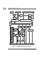
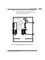
Block Diagram
Polyswitches (Resettable Fuses)
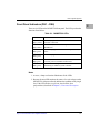
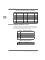
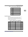
The MVME2700 base board draws fused +5V DC, +12V DC, and
–12V DC power from the VMEbus backplane through connectors P1 and
P2. The 3.3V DC and 2.5V DC power is derived on-board from the
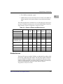
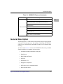
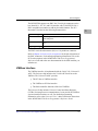
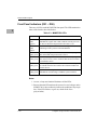
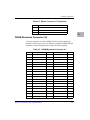
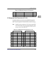
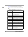
+5V DC. The following table lists the fuses with the voltages they protect.
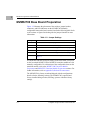
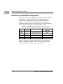
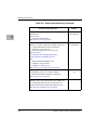
Table 3-4. Fuse Assignments
Fuse
Voltage
F1
+5V DC
F2
+12V DC
F3
–12V DC (used on
MVME761 versions)
I/O Power
The MVME2700 base board furnishes +12V DC and (in MVME761 I/O
versions) –12V DC power to the transition module through polyswitches
(resettable fuses) F2 and F3 respectively. These voltage sources power the
serial port drivers and any LAN transceivers connected to the transition
module. Fused +5V DC power is supplied through polyswitch F1to the
base board’s keyboard and mouse connectors and to the 14-pin combined
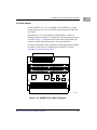
LED-mezzanine/remote-reset connector, J1. The FUS LED (DS5) on the
MVME2700 front panel illuminates when all three voltages are available.
In MVME712M I/O mode, the yellow DS1 LED on the MVME712M also
signals the availability of +12V DC LAN power, indicating in turn that
polyswitch F2 is good. If the Ethernet transceiver fails to operate, check
polyswitch F2.
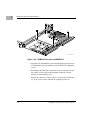
In MVME712M I/O mode, the MVME2700 supplies SCSI terminator
power through a 1A fuse (F1) located on the P2 adapter board. If the fuse
is blown, the SCSI device(s) may function erratically or not at all. With the
P2 adapter board cabled to a transition module and with an SCSI bus
connected to the transition module, the green SCSI LED on the module
illuminates when SCSI terminator power is available. If the SCSI LED on
the transition module flickers during SCSI bus operation, check fuse F1 on
the P2 adapter board.
http://www.motorola.com/computer/literature
3-21
3