1
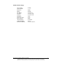
One Port Serial Server Users Manual
Model ESP901, ESP901E
Documentation Number: ESP901-2303
International Headquarters
B&B Electronics Mfg. Co. Inc.
707 Dayton Road -- P.O. Box 1040 -- Ottawa, IL 61350 USA
Phone (815) 433-5100 -- General Fax (815) 433-5105
Home Page: www.bb-elec.com
Sales e-mail: [email protected] -- Fax (815) 433-5109
Technical Support e-mail: [email protected] -- Fax (815) 433-5104
European Headquarters
B&B Electronics Ltd.
Westlink Commercial Park, Oranmore, Co. Galway, Ireland
Phone +353 91-792444 -- Fax +353 91-792445
Home Page: www.bb-europe.com
Sales e-mail: [email protected]
Technical Support e-mail: [email protected]
B&B Electronics – June 2003
Documentation Number: ESP901-2303 Manual
B&B Electronics Mfg Co Inc – 707 Dayton Rd - PO Box 1040 - Ottawa IL 61350 - Ph 815-433-5100 - Fax 815-433-5104
B&B Electronics Ltd – Westlink Commercial Park – Oranmore, Galway, Ireland – Ph +353 91-792444 – Fax +353 91-792445
Title Page
Table of Contents
1
Introduction ..................................................................................... 1
Features............................................................................................................ 1
Product Specifications .................................................................................... 2
Protocol ............................................................................................................ 2
Management .................................................................................................... 2
Power & Environment.................................................................................... 2
Default Settings ............................................................................................... 3
2
Making the Hardware Connections................................................ 4
Serial Connection ............................................................................................ 4
Power Connection ........................................................................................... 4
Ethernet Connection ....................................................................................... 4
Reset Button .................................................................................................... 4
LED .................................................................................................................. 4
Dip Switch Setting........................................................................................... 5
Console......................................................................................................... 5
Upgrade........................................................................................................ 5
Default Setting............................................................................................. 5
IP - RS232 Bridge........................................................................................ 6
IP - RS422 Bridge........................................................................................ 6
IP - RS485 Bridge........................................................................................ 6
RS-485 Bias Resistors ................................................................................. 6
3
Vlinx ESP901 Software Installation............................................... 8
4
Quick Start Using Management Software.................................... 12
Searching LAN for ESP901.......................................................................... 12
Configuration Screen.................................................................................... 13
Setting the IP address, Netmask, and Gateway fields................................ 14
Configuring the serial port settings ............................................................. 15
Configuring the mode of operation ............................................................. 15
Setting TCP/UDP protocol ........................................................................... 16
TCP/UDP Port............................................................................................... 16
Remote IP address ........................................................................................ 16
Saving the changes ........................................................................................ 16
5
Installing Virtual COM Port......................................................... 17
Installing Virtual COM Port ........................................................................... 17
6
Setup Menu.................................................................................... 20
Documentation Number: ESP901-2303 Manual
B&B Electronics Mfg Co Inc – 707 Dayton Rd - PO Box 1040 - Ottawa IL 61350 - Ph 815-433-5100 - Fax 815-433-5104
B&B Electronics Ltd – Westlink Commercial Park – Oranmore, Galway, Ireland – Ph +353 91-792444 – Fax +353 91-792445
i
7
Console Mode Setup...................................................................... 23
8
Communication Modes ................................................................. 25
Direct IP mode............................................................................................... 25
Virtual COM mode ....................................................................................... 25
Paired mode................................................................................................... 26
Heart Beat ....................................................................................................... 26
9
Configuring Virtual COM Port .................................................... 27
Configuration with Management Software ................................................ 27
Configuration with Device Manager ........................................................... 28
10
Uninstalling the Virtual COM Port........................................... 30
Removing the Virtual COM port with ESP901 Management software ... 30
Removal of the Virtual COM port using the Device Manager ................. 31
11
Upgrade Mode ............................................................................ 33
Serial Port / Virtual COM............................................................................ 33
ii
Documentation Number: ESP901-2303 Manual
B&B Electronics Mfg Co Inc – 707 Dayton Rd - PO Box 1040 - Ottawa IL 61350 - Ph 815-433-5100 - Fax 815-433-5104
B&B Electronics Ltd – Westlink Commercial Park – Oranmore, Galway, Ireland – Ph +353 91-792444 – Fax +353 91-792445
1
Introduction
The Vlinx model ESP901Ethernet serial server connects RS-232, 422, 485 serial
devices to an Ethernet LAN/WAN providing a reliable communication connection.
Existing Windows based serial software using standard Windows API does not have
to be modified to communicate over an Ethernet LAN to a serial device. The Vlinx
virtual COM port will make this an easy transition.
The ESP901 operates in “Direct IP Mode”, “Virtual COM Mode”, and “Paired
Mode”. The ESP901 has one asynchronous DB-9 serial port and one 10/100 Mbps
Ethernet RJ-45 connection. The Ethernet port will auto-select 10BaseT or
100BaseTX.
The ESP901 Windows driver installs a virtual COM port in the Device Manager of
the operating system. The virtual COM port is designed to establish a connection with
the ESP901. This in turn will allow communications with the connected serial device
in the same manner as a device connected to the COM port on a PC. The LAN
becomes transparent to the serial device and the software running on the PC.
The ESP901 can be configured as a TCP or UDP Client/Server. In direct IP and
virtual COM modes, ESP901 should be configured as a server. ESP901 also offers a
Heart Beat feature to insure a reliable communications connection.
Features
DIN rail or Panel mount
Supports 10/100 Mbps Ethernet
Supports RS-232, RS-422, and RS-485 serial interface
Supports LAN and WAN communications
In Server mode supports individual client sessions for security.
Management access password protected.
Virtual COM drivers for Window NT/98/ME/2000/XP
Documentation Number: ESP901-2303 Manual
B&B Electronics Mfg Co Inc – 707 Dayton Rd - PO Box 1040 - Ottawa IL 61350 - Ph 815-433-5100 - Fax 815-433-5104
B&B Electronics Ltd – Westlink Commercial Park – Oranmore, Galway, Ireland – Ph +353 91-792444 – Fax +353 91-792445
1
Product Specifications
Serial Memory:
Serial Connection:
Interface:
Serial:
LAN:
Supported Signals:
Data Rate:
Parity:
Data Bits:
Stop Bits:
64K bytes
DTE – BD-9 male
One-RS-232, RS-422, OR RS-485
Dip Switch Selectable
10/100 Mbps Auto-detecting – 10 Base T,
100 Base TX
RS-232 - TX, RX, RTS, CTS, DTR, DSR,
DCD, GND
RS-422 – TX+, TX-, RX+, RX-, RTS+, RTS-, C
TS+, CTS-, GND
RS-485 - Data +, Data –
110 bps to 230.4 k bps
none, even, odd
7, 8
1, 2
Protocol
TCP, IP, ARP, DHCP, Telnet, HTTP, UDP, ICMP
Management
Vlinx Manager, Serial Console, Telnet
(Soon to be released Web server)
Firmware upgradeable
Power & Environment
Power Requirements:
Operating Temperature:
Storage Temperature:
Humidity:
Approvals:
12 VDC @ 200 mA
0 to 50 °C (32 to 122 °F)
-20 to 60 °C (-4 to 140 °F)
0 – 90% Non-Condensing
CE, FCC
Dimensions: 3.35 x 4.5 x 0.90 in (8.5 x 11.5 x 2.3 cm)
2
Documentation Number: ESP901-2303 Manual
B&B Electronics Mfg Co Inc – 707 Dayton Rd - PO Box 1040 - Ottawa IL 61350 - Ph 815-433-5100 - Fax 815-433-5104
B&B Electronics Ltd – Westlink Commercial Park – Oranmore, Galway, Ireland – Ph +353 91-792444 – Fax +353 91-792445
ESP901 Default Settings
Server Name:
Serial Number:
Password:
DHCP:
IP Address:
Net Mask:
Gateway :
Baud Rate:
Data/Parity/Stop:
Flow Control:
TCP/UDP Port:
Connection Mode:
Remote IP Address:
ESP901
Blank
Disable
192.168.0.1
255.255.255.0
192.168.0.254
9600
8-N-1
None
TCP 4000
Server
255.255.255.255
Documentation Number: ESP901-2303 Manual
B&B Electronics Mfg Co Inc – 707 Dayton Rd - PO Box 1040 - Ottawa IL 61350 - Ph 815-433-5100 - Fax 815-433-5104
B&B Electronics Ltd – Westlink Commercial Park – Oranmore, Galway, Ireland – Ph +353 91-792444 – Fax +353 91-792445
3
2
Making the Hardware Connections
The following information is provided to give the user an understanding of how to
connect the ESP901 to the LAN and serial device. A review of the switch settings and
the functionality of the LED’s are also provided.
Serial Connection
The ESP901 has a DB-9 male connector. The serial port is configured as a DTE (data
terminal equipment) device. All PC COM ports are DTE ports. A null modem cable is
required to make a connection between the COM port on a PC and the ESP901 serial
port. A straight through cable is required to connect the ESP901 serial port to a DCE
device.
Power Connection
The ESP901 is shipped with a 12 VDC 500mA power supply. The tip of the connector
is positive. When inserted into the jack the red power light will illuminate confirming
power has been supplied to the unit.
Ethernet Connection
A straight-through Ethernet cable can be used to connect the serial server to an
Ethernet hub, switch, or wall plate. A crossover Ethernet cable can be used to make a
connection directly to the NIC (Network Interface Card) on a PC or laptop.
Reset Button
The reset button can be found between the switch and power jack. To reset the unit
manually apply power, insert a small plastic tool, and press lightly depressing switch.
Hold for 3 seconds and release. The Link and Ready light will go out and turn back
on.
LED Definition
Led Name
Power
Link
Ready
4
Led Function
Red - Power has been supplied
Green – 100 BaseTX Ethernet connection established
Yellow – 10 BaseT Ethernet connection established
Flashing Green – system is ready
Documentation Number: ESP901-2303 Manual
B&B Electronics Mfg Co Inc – 707 Dayton Rd - PO Box 1040 - Ottawa IL 61350 - Ph 815-433-5100 - Fax 815-433-5104
B&B Electronics Ltd – Westlink Commercial Park – Oranmore, Galway, Ireland – Ph +353 91-792444 – Fax +353 91-792445
Dip Switch Settings
There are 6 operation modes defined by the 3 switches. They are defined in the
following table.
Sw1
On
Off
On
Off
On
Off
Sw2
On
On
Off
On
Off
Off
Sw3
On
On
On
Off
Off
Off
Mode
Console
Upgrade
Default
RS-232
RS-422
RS-485
Console Mode
The console mode allows access to the ESP901 setup menu. This is one way to
reconfigure the default settings for the application. A serial connection is made
between a COM port on the PC and the serial port of the ESP901 with a null modem
cable. In console mode, the serial port defaults to an RS-232 interface.
The ESP901 serial port default settings are, baud rate 9600, 8 data bits, no parity, and
1 stop bit. Hyper Terminal should be used for this type of setup. Hyper Terminal’s
serial settings are configured the same as the mentioned default settings of the ESP901
and must be set to VT100 emulation mode. The default settings are used only if they
have not been changed.
See Chapter 7 for details.
Upgrade
The newest firmware can be installed on the ESP901 using the PC’s serial port or the
Virtual COM port. Some firmware upgrades may require a new software upgrade with
the Virtual COM driver being the critical component.
See Chapter 11 for details.
Default Setting
When the switches are set to this mode the ESP901 will reset to the original default
settings.
Documentation Number: ESP901-2303 Manual
B&B Electronics Mfg Co Inc – 707 Dayton Rd - PO Box 1040 - Ottawa IL 61350 - Ph 815-433-5100 - Fax 815-433-5104
B&B Electronics Ltd – Westlink Commercial Park – Oranmore, Galway, Ireland – Ph +353 91-792444 – Fax +353 91-792445
5
RS-232 Interface
The RS-232 supports 8 channels plus Signal Ground and is configured as DTE like a
computer. Signals are single ended and referenced to Ground. To used handshaking,
Flow Control must be set to RTS/CTS during Configuration. Refer to the Pin out
table for connections.
RS-422 Interface
The RS-422 mode supports 4 channels with full duplex operation for Receive,
Transmit, RTS (Request To Send) and CTS (Clear To Send). The data lines are in
differential pairs with the B lines positive relative to the A lines. Ground provides a
common mode reference. To use handshaking Flow Control must be set to RTS/CTS
during configuration. Refer to the Pin out table for connections.
RS-485 Interface
The RS-485 mode supports the Transmit and Receive Channels using 2-wire halfduplex operation. The data lines are differential with the Data B line positive relative
to Data A in the Mark state. Ground provides a common mode reference. Refer to
the Pin out table for connections.
Internal Setting To Select RS-485 Bias
You can select RS-485 Receiver Biasing from the ESP901 if your network doesn’t
supply any. Remove the two side cover screws, slide the cover off, and then set the
two bias jumpers (shown open) to enable biasing (shorting).
6
Documentation Number: ESP901-2303 Manual
B&B Electronics Mfg Co Inc – 707 Dayton Rd - PO Box 1040 - Ottawa IL 61350 - Ph 815-433-5100 - Fax 815-433-5104
B&B Electronics Ltd – Westlink Commercial Park – Oranmore, Galway, Ireland – Ph +353 91-792444 – Fax +353 91-792445
DB9 Pin Configuration
Pin
1
2
3
4
5
6
7
8
9
RS-232
DCD
RXD
TXD
DTR
GND
DSR
RTS
CTS
RI
RS-422
RXDA (-)
RXDB (+)
TXDB (+)
TXDA (-)
GND
CTSA (-)
CTSB (+)
RTSB (+)
RTSA (-)
RS-485
DATA B (+)
DATA A (-)
GND
Documentation Number: ESP901-2303 Manual
B&B Electronics Mfg Co Inc – 707 Dayton Rd - PO Box 1040 - Ottawa IL 61350 - Ph 815-433-5100 - Fax 815-433-5104
B&B Electronics Ltd – Westlink Commercial Park – Oranmore, Galway, Ireland – Ph +353 91-792444 – Fax +353 91-792445
7
3
Vlinx ESP901 Software Installation
It is recommended the user install the Management software and do a search for all
ESP901’s connected to the LAN. When this is completed a window will list the
devices making them available for configuration.
Configuring the serial server to meet your LAN and application requirement is an easy
process with the available setup menu in the management software.
The following procedure installs the Vlinx’s ESP901 management software.
1.
Inserting the Vlinx CD in the CD-ROM will automatically launch the Install
Shield Wizard.
To manually start the software installation, select the Start button on the
desktop. At the Run command line type D:start.exe Then select OK. The D:
is the drive letter for the CD Rom.
2.
8
The Install Shield Wizard window automatically displays to begin the setup
procedure.
Documentation Number: ESP901-2303 Manual
B&B Electronics Mfg Co Inc – 707 Dayton Rd - PO Box 1040 - Ottawa IL 61350 - Ph 815-433-5100 - Fax 815-433-5104
B&B Electronics Ltd – Westlink Commercial Park – Oranmore, Galway, Ireland – Ph +353 91-792444 – Fax +353 91-792445
3.
Select Next when the ESP901 Setup window appears.
4.
In the Choose Destination Location window select Next to install the
manager software in the default location. Select Browse to install into a user
selected directory.
Documentation Number: ESP901-2303 Manual
B&B Electronics Mfg Co Inc – 707 Dayton Rd - PO Box 1040 - Ottawa IL 61350 - Ph 815-433-5100 - Fax 815-433-5104
B&B Electronics Ltd – Westlink Commercial Park – Oranmore, Galway, Ireland – Ph +353 91-792444 – Fax +353 91-792445
9
10
5.
The Setup Status window displays the progress of the installation.
6.
Select Finish when the Install Shield Wizard Complete screen appears.
Documentation Number: ESP901-2303 Manual
B&B Electronics Mfg Co Inc – 707 Dayton Rd - PO Box 1040 - Ottawa IL 61350 - Ph 815-433-5100 - Fax 815-433-5104
B&B Electronics Ltd – Westlink Commercial Park – Oranmore, Galway, Ireland – Ph +353 91-792444 – Fax +353 91-792445
When the installation is complete the Install window closes allowing the user to
access the management software in the program files. If loaded in the default location
Go to Start/Programs/B&B Electronics/Vlinx/ESP Server/ Vlinx ESP Manager to
open.
Connect the ESP901 to the LAN and apply power. The red LED indicates power has
been applied; the Link LED indicates an Ethernet connection has been made; and the
Ready LED will flash indicating communications with the unit can begin.
Documentation Number: ESP901-2303 Manual
B&B Electronics Mfg Co Inc – 707 Dayton Rd - PO Box 1040 - Ottawa IL 61350 - Ph 815-433-5100 - Fax 815-433-5104
B&B Electronics Ltd – Westlink Commercial Park – Oranmore, Galway, Ireland – Ph +353 91-792444 – Fax +353 91-792445
11
4
Quick Start Using Management Software
The manager software performs several functions, Uninstall Virtual COM port,
Searching LAN for ESP901, Configure ESP901, Configure Virtual COM Port, and
upgrade Firmware.
Connect the ESP901 to the LAN and apply power. The red LED indicates power has
been applied, the Link LED indicates an Ethernet connection has been made, and the
Ready LED will flash indicating communications with the unit can begin. See section
2 for Hardware Connections.
Once the ESP901 is connected to the LAN the management software will be able to
search the LAN for all connected ESP901 servers and will display them in a window
by name and IP address.
Searching LAN for ESP901
1.
12
Select ESP901 Manager in the program file menu. If the default location was
selected during the installation the program will be found under
Start/Programs/B&B Electronics/Vlinx/ESP Server. Select VLINX ESP
Manager.
Documentation Number: ESP901-2303 Manual
B&B Electronics Mfg Co Inc – 707 Dayton Rd - PO Box 1040 - Ottawa IL 61350 - Ph 815-433-5100 - Fax 815-433-5104
B&B Electronics Ltd – Westlink Commercial Park – Oranmore, Galway, Ireland – Ph +353 91-792444 – Fax +353 91-792445
2.
On the menu side bar select Searching ESP901 button. The Searching for
ESP901 window opens and all ESP901 serial servers connected on the LAN
are listed in the Manager Window.
Configuration Screen
Highlight the serial server in the Manager Window and double click to open the
configuration menu options.
Documentation Number: ESP901-2303 Manual
B&B Electronics Mfg Co Inc – 707 Dayton Rd - PO Box 1040 - Ottawa IL 61350 - Ph 815-433-5100 - Fax 815-433-5104
B&B Electronics Ltd – Westlink Commercial Park – Oranmore, Galway, Ireland – Ph +353 91-792444 – Fax +353 91-792445
13
From the Server Properties menu the serial server IP address, Net Mask,
Gateway, serial port settings and operation mode can be programmed into the
unit. Select update and restart the ESP901 once all settings are changed to
conform to the desired application.
Details on Menu settings can be found in Chapter 6.
Setting the IP Address, Netmask, and Gateway Fields
It is recommended to use a static IP address. The most commonly used option is to
contact the network administrator and request a static IP address. The administrator
will also have the Netmask and Gateway address information.
Select the tab button to move to the next adjustable field in the menu. The arrow keys
will scroll the option available in each field.
Start by tabbing to the IP address field and insert the new IP address. Follow the same
procedure with the Netmask and Gateway fields. All three fields will have to conform
to your LAN for proper operation.
14
Documentation Number: ESP901-2303 Manual
B&B Electronics Mfg Co Inc – 707 Dayton Rd - PO Box 1040 - Ottawa IL 61350 - Ph 815-433-5100 - Fax 815-433-5104
B&B Electronics Ltd – Westlink Commercial Park – Oranmore, Galway, Ireland – Ph +353 91-792444 – Fax +353 91-792445
Configuring the Serial Port Settings
Use the Tab key to advance to the baud rate, Data/Parity/Stop bits, and Flow
control section of the menu. Use the arrow keys to advance to a selection that
matches the connected serial device. The serial port settings must match the
connected serial device when using TCP/UDP socket programs. If the ESP
Virtual COM driver is used the application software will control the ESP901
serial port setting.
Configuring the Mode of Operation
It must first be decided what Operation Mode is going to fit the application.
Connection mode has 2 options, client and server.
• When using the Virtual COM port feature select Server
• When using socket software select Server
• When using paired connection mode set one to server and one to
client.
For more details see section 8, Communication Modes.
Documentation Number: ESP901-2303 Manual
B&B Electronics Mfg Co Inc – 707 Dayton Rd - PO Box 1040 - Ottawa IL 61350 - Ph 815-433-5100 - Fax 815-433-5104
B&B Electronics Ltd – Westlink Commercial Park – Oranmore, Galway, Ireland – Ph +353 91-792444 – Fax +353 91-792445
15
Setting TCP/UDP Protocol
The most common protocol is TCP. The default setting is TCP and should not be
changed unless your application specifies a UDP protocol.
TCP/UDP Port
The default port number is 4000. The TCP/UDP Port defines a communication
port. In all modes of operating, Virtual COM, Direct IP, and Paired modes, both
the TCP/UDP Client and server port settings must match.
As an example the Virtual COM default setting TCP/UDP Port # 4000. If the port
# in the setup menu is changed to 4001 the Virtual COM TCP/UDP Port will
have to be changed to 4001.
The change can be made in the Device Manager of the operating system or using
the ESP901 Manager software.
Remote IP Address
The default setting is 255.255.255.255. It is recommended not to change this
setting until the application has been tested and is communicating properly. At
that point the address filtering feature of the ESP901 can be activated. Refer to
the Menu Overview section for more details.
Saving the Changes
To save the changes select the update button.
Reset the ESP901
Close the menu
16
Documentation Number: ESP901-2303 Manual
B&B Electronics Mfg Co Inc – 707 Dayton Rd - PO Box 1040 - Ottawa IL 61350 - Ph 815-433-5100 - Fax 815-433-5104
B&B Electronics Ltd – Westlink Commercial Park – Oranmore, Galway, Ireland – Ph +353 91-792444 – Fax +353 91-792445
5
Installing Virtual COM Port
The Virtual COM Port feature allows Windows platform software using standard
API calls to be used in an Ethernet application.
Running the Install Virtual COM port software adds a COM Port in the Device
Manager of the operating system. The COM port will look like a standard COM
port to Windows software used in most applications allowing the software to
open a connection with the serial port located anywhere on the LAN. When using
the virtual COM port the ESP901 is configured as a TCP or UDP Server.
1.
On the Desk Top select Start/Programs/B&B Electronics/Vlinx/ Vlinx
Server/Install Virtual COM.
2.
The Install Virtual COM program will automatically search the LAN for all
available ESP901 serial servers and display them in the Found ESP901
window. Highlight the desired serial server and select OK.
Documentation Number: ESP901-2303 Manual
B&B Electronics Mfg Co Inc – 707 Dayton Rd - PO Box 1040 - Ottawa IL 61350 - Ph 815-433-5100 - Fax 815-433-5104
B&B Electronics Ltd – Westlink Commercial Park – Oranmore, Galway, Ireland – Ph +353 91-792444 – Fax +353 91-792445
17
3.
When the COMInst window opens select COM port # to map the serial
server to. The default Flow Control setting is None. An RTS/CTS option is
available if used by the application program and serial hardware. The
Protocol, IP Address, and Port Number will mirror the settings of the
selected serial server.
If any settings are changed in this part of the Virtual COM setup it will only
affect the settings in the operating system Device Manager. It will not change
the settings in the ESP901.
The settings of the Virtual COM port in the Device Manager and the ESP901
Configuration menu must match. If the settings do not, the software
connecting to the Virtual COM port will be unsuccessful in opening the
COM port. Highlight the desired COM port # and select OK.
18
Documentation Number: ESP901-2303 Manual
B&B Electronics Mfg Co Inc – 707 Dayton Rd - PO Box 1040 - Ottawa IL 61350 - Ph 815-433-5100 - Fax 815-433-5104
B&B Electronics Ltd – Westlink Commercial Park – Oranmore, Galway, Ireland – Ph +353 91-792444 – Fax +353 91-792445
4.
Note: Your PC may have hardware COM ports and devices such as Modems
loaded on COM’s 1, 2, 3, or 4. It is recommended that the Virtual COM port
selected start on COM 5 or higher.
In Windows XP a Hardware Installation window stating that the drivers have
not been tested by Microsoft may appear. Select “Continue Anyway” to
proceed with the installation.
5.
To confirm installation, go to the Device Manager and select Ports (COM &
LPT). The installed Virtual COM port will be displayed as ESP Vlinx COM#.
Documentation Number: ESP901-2303 Manual
B&B Electronics Mfg Co Inc – 707 Dayton Rd - PO Box 1040 - Ottawa IL 61350 - Ph 815-433-5100 - Fax 815-433-5104
B&B Electronics Ltd – Westlink Commercial Park – Oranmore, Galway, Ireland – Ph +353 91-792444 – Fax +353 91-792445
19
6
Setup Menu
There are three ways to access the setup menu and program the ESP901, Management
software, Console mode, and Telnet. The menu pictured above displays in the ESP901
Management software setup screen.
Instructions on how to move around the menu and change settings pertains to the
Management setup menu but are similar in Telnet.
There are a few pre-defined keys to move around the menu and to save changes.
Space Bar:
TAB:
Back Space:
Arrow Keys:
Enter:
To refresh the configuration page.
To move the cursor to next field.
To move the cursor to previous field.
To move the cursor around the configuration page.
Telnet only - To open 2nd window of selections, confirm a selected
change, or to activate the save, default, reset and status.
Server Name
The server name is user configurable. It is recommended users with more than one
ESP901 connected to the LAN assign a new name to each. When the Manager
software searches for servers on the LAN it will display the server name allowing the
user to distinguish between ESP901’s.
Password
Entering a password activates a security feature on the serial server. Once a password
is entered it will be required to access the menu and make changes.
DHCP
DHCP servers are a part of numerous LAN management systems. The DHCP field
has two selections, “Enable” or “Disable”. Arrow to the desired selection and select
enter.
When enabled, ESP901 will send a DHCP request to the DHCP server, which will
assign a dynamic IP address, net mask, and gateway to the ESP901. If a DHCP server
is not available on the network the ESP901 will time out after 10 seconds and the
default values will remain.
20
Documentation Number: ESP901-2303 Manual
B&B Electronics Mfg Co Inc – 707 Dayton Rd - PO Box 1040 - Ottawa IL 61350 - Ph 815-433-5100 - Fax 815-433-5104
B&B Electronics Ltd – Westlink Commercial Park – Oranmore, Galway, Ireland – Ph +353 91-792444 – Fax +353 91-792445
IP Address
A static IP address can also be assigned in this section of the menu. A dynamic
address assigned by the DHCP server may change if the ESP901 looses the Ethernet
connection or power is removed. The host (client) communication software requests a
connection to the specific IP address of the serial server. If the DHCP reassigns a
different IP address the software will not be able to communicate with the hardware. It
is recommended to use a static IP address.
A static IP address is permanent and will not change unless changed in the menu. In
most cases the network administrator establishes the static address to be used.
Net Mask
The default LAN net mask is configured for a Class C address. This maybe
reconfigured by the user.
Gateway
The gateway IP address allows users to access the serial server from outside the LAN.
MAC Address
The MAC address is not adjustable. This is assigned in the factory. Every Ethernet
device manufactured has it own unique MAC address.
Link Status
Link status automatically displays the type of Ethernet connection. It will either
display 10 BaseT or 100BaseTX in full duplex or half duplex. This will depend on the
LAN, switches, hubs used in the LAN topology.
Baud Rate
The serial port baud rate on the ESP901 must match the serial baud rate of the
connected device unless using Virtual COM mode. In Virtual COM mode the
software program will establish serial settings. Use the arrow keys to change the
setting to the desired baud rate.
Data/Parity/Stop
This setting will have to match the data format of the connected device. Tab to the
Data/Parity/Stop field and arrow to the desired selection.
Documentation Number: ESP901-2303 Manual
B&B Electronics Mfg Co Inc – 707 Dayton Rd - PO Box 1040 - Ottawa IL 61350 - Ph 815-433-5100 - Fax 815-433-5104
B&B Electronics Ltd – Westlink Commercial Park – Oranmore, Galway, Ireland – Ph +353 91-792444 – Fax +353 91-792445
21
Flow Control
The flow control setting must match the connected serial device. Tab to the Flow
Control field and arrow to None or RTS/CTS.
TCP/UDP Port
Tab to the first field and select TCP or UDP protocol. If the user’s application does
not require a UDP connection it is recommended to use TCP. TCP guarantees reliable
communication through the use of error checking.
The second field chooses the port number of the connection. A predefined TCP port,
5300, is reserved for the Heart Beat. See Chapter 4 for details on the Heart Beat
feature.
Connection Mode
The Connection mode has two options, Client and Server. To setup Paired Mode two
ESP901 serial servers are required, with one setup as the server and the second setup
as a client.
A single ESP901 is setup in the server mode to establish a Windows Virtual COM
connection or a raw TCP or UDP connection.
Remote IP Address
This is a security feature that is activated when the IP address of the desired client is
programmed into the remote IP Address setting of the menu. This tells the ESP901 to
communicate with only the listed IP address and to filter out all other requests for
connection. The ESP901 is setup in the menu as a TCP or UDP server to us this
feature.
There are five buttons at the bottom of the menu, “Save”, “Default”, “Running”,
“Reset” and Status. The user can use TAB, Backspace, or arrow keys to move cursor
to the button’s position, and then press enter. The “Save” action stores the
configuration data to flash. The user must reset the device for the stored configuration
data to take effect. The “Default” button restores the editing configuration data to
default menu settings. The “Running” button restores the editing configuration data
to the value that stored in the flash. For the edited value to take effect, user need to
save the configuration data, then reset the device. The Status button displays how
many Ethernet packets and serial bytes are transmitted and receive. A refresh button is
available to update the displayed figures.
22
Documentation Number: ESP901-2303 Manual
B&B Electronics Mfg Co Inc – 707 Dayton Rd - PO Box 1040 - Ottawa IL 61350 - Ph 815-433-5100 - Fax 815-433-5104
B&B Electronics Ltd – Westlink Commercial Park – Oranmore, Galway, Ireland – Ph +353 91-792444 – Fax +353 91-792445
7
Console Mode Setup
Before the ESP901 is installed on a LAN the Console Mode can be used to change the
default the settings. Connect a null modem cable between the serial port on the ES901
and the COM port on the PC. Apply power to the ESP901. The power and ready LED
will light.
Using Hyper Terminal open the connected PC COM port at a baud rate of 9600, Data
bits 8, Parity None, Stop bits 1, and Flow control None.
To view the menu hit the space bar. Use the arrow keys to select the desired field. The
following fields have a selection table to choose from, DHCP, Baud Rate,
Data/Parity/Stop, Flow control, TCP/UDP port and Connection mode. To view the
options arrow to the field and select enter.
Once all the changes have been made move to the Save field and select enter.
Documentation Number: ESP901-2303 Manual
B&B Electronics Mfg Co Inc – 707 Dayton Rd - PO Box 1040 - Ottawa IL 61350 - Ph 815-433-5100 - Fax 815-433-5104
B&B Electronics Ltd – Westlink Commercial Park – Oranmore, Galway, Ireland – Ph +353 91-792444 – Fax +353 91-792445
23
The restart screen will appear. Select Yes to save changes. This is necessary to write
the settings to the server. To view the changes press the space bar. The screen will
reappear.
24
Documentation Number: ESP901-2303 Manual
B&B Electronics Mfg Co Inc – 707 Dayton Rd - PO Box 1040 - Ottawa IL 61350 - Ph 815-433-5100 - Fax 815-433-5104
B&B Electronics Ltd – Westlink Commercial Park – Oranmore, Galway, Ireland – Ph +353 91-792444 – Fax +353 91-792445
8
Communication Modes
The ESP901 allows serial devices to communicate over a LAN or Intranet network.
Serial devices are no longer limited to a physical connection to the PC COM port.
They can be installed anywhere on the LAN using TCP/IP or UDP/IP
communications. This will also allow traditional PC COM ports access to a serial
device anywhere on the LAN network.
Direct IP Mode
Direct IP connections allow applications using TCP/IP or UDP/IP network socket
programs to communicate with the asynchronous serial port on the ESP901. In this
type of application the ESP901 is configured to TCP or UDP server. The socket
program running on the PC establishes a communication connection with the ESP901.
The raw data is sent directly to and from the serial port.
Virtual COM Mode
The Virtual COM mode requires the installation of a driver. When installed a new
COM port is added to the Device Manager. Windows programs using standard
Windows API calls will be able to interface with Virtual ports. The PC will act as the
host connecting to the ESP901 when the program opens the virtual COM port.
Once the connection is made, the LAN is transparent to the serial device. Applications
work just as if the serial device is connected a host’s physical COM port. The virtual
COM port converts the application’s data into IP packet destined for the ESP901,
which in turn converts the IP packet back to serial data.
In this mode, the ESP901 must be set to either TCP/server or UDP/server in the menu
with a designated communication port number. The virtual COM driver is a TCP or
UDP client.
Documentation Number: ESP901-2303 Manual
B&B Electronics Mfg Co Inc – 707 Dayton Rd - PO Box 1040 - Ottawa IL 61350 - Ph 815-433-5100 - Fax 815-433-5104
B&B Electronics Ltd – Westlink Commercial Park – Oranmore, Galway, Ireland – Ph +353 91-792444 – Fax +353 91-792445
25
Paired Mode (Serial Tunneling)
Paired mode is also called serial tunneling. When this type of configuration is selected
additional software will not have to be loaded on a host PC. In fact a PC is not
required to make the connection. Any two dumb serial devices that can communicate
with each other through a serial link will be able to communicate using two ESP901’s
and the LAN.
Two ESP901’s are configured with one setup as a TCP or UDP client and the other to
TCP/UDP server. When setting up the Server, the Remote IP address section must
contain the address of the Client. This will allow the Client’s IP address to pass the IP
address-filtering feature of the Server. Conversely the Remote IP address of the Client
must contain the Servers IP address.
Heart Beat
The ESP901 provides a convenient way to establish reliable communications between
two devices. Communication port 5300 is reserved for the Heartbeat Protocol.
Without this feature a device that loses a connection and stops communicating would
not be able to reconnect without personally attending to the problem. A TCP data
connection can be lost when there is a power failure or temporary loss of an Ethernet
connection on either the client or server.
If a loss occurs the Heart Beat feature will try to reconnect the TCP data connection
every 5 seconds until communications is established again. The Heart Beat feature is
available to use with the Virtual COM port mode and TCP Direct IP connection. This
is not available when using a UDP application.
26
Documentation Number: ESP901-2303 Manual
B&B Electronics Mfg Co Inc – 707 Dayton Rd - PO Box 1040 - Ottawa IL 61350 - Ph 815-433-5100 - Fax 815-433-5104
B&B Electronics Ltd – Westlink Commercial Park – Oranmore, Galway, Ireland – Ph +353 91-792444 – Fax +353 91-792445
9
Configuring Virtual COM Port
The Virtual COM port can be configured in the Device Manager of the operating
system or the Management software. In either case the IP Address, Port #,
Protocol, and Flow Control settings must match the ESP901 settings for the
software to open the Virtual COM port.
Configuration with Management Software
1.
At the Desk Top select Start/Programs/B&B Electronics/Vlinx/ ESP Vlinx/
ESP Manager. Double click the Virtual COM Configuration button.
2.
Double click the COM # displayed in the screen to open the configuration
window.
Documentation Number: ESP901-2303 Manual
B&B Electronics Mfg Co Inc – 707 Dayton Rd - PO Box 1040 - Ottawa IL 61350 - Ph 815-433-5100 - Fax 815-433-5104
B&B Electronics Ltd – Westlink Commercial Park – Oranmore, Galway, Ireland – Ph +353 91-792444 – Fax +353 91-792445
27
3.
Make the adjustments and select OK to complete the changes.
Configuration with Device Manager
28
1.
On the Desk Top select Start/Settings/Control Panel. Select the System Icon
when the Control Panel window opens.
2.
In the System Properties window select the Device Manager button.
(Windows XP window shown.)
Documentation Number: ESP901-2303 Manual
B&B Electronics Mfg Co Inc – 707 Dayton Rd - PO Box 1040 - Ottawa IL 61350 - Ph 815-433-5100 - Fax 815-433-5104
B&B Electronics Ltd – Westlink Commercial Park – Oranmore, Galway, Ireland – Ph +353 91-792444 – Fax +353 91-792445
3.
In the Device Manager select the + button next to Ports (COM & LPT) to
expand and see the Vlinx ESP (COM #). Double click Vlinx ESP (COM #)
to open the Properties window.
4.
Select the Configuration tab. From here the same settings found in the
ESP901 Manager can be adjusted.
Documentation Number: ESP901-2303 Manual
B&B Electronics Mfg Co Inc – 707 Dayton Rd - PO Box 1040 - Ottawa IL 61350 - Ph 815-433-5100 - Fax 815-433-5104
B&B Electronics Ltd – Westlink Commercial Park – Oranmore, Galway, Ireland – Ph +353 91-792444 – Fax +353 91-792445
29
10 Uninstalling the Virtual COM Port
The ESP901 Management software Uninstall Virtual Com port feature will
remove the mapped COM port in the Device Manager of Windows 2000 and XP
operating systems. It may also be removed in the Device Manager of Windows
98, ME, NT, 2000, and XP. Windows 98 users will also find a Remove Virtual
COM feature in the programs file.
Removing the Virtual COM port with the ESP901 Management Software
30
1.
At the Desk Top select Start/Programs/B&B Electronics/Vlinx/ ESP
Manager/Vlinx ESP Manager
2.
In the Manager window select Virtual COM Configuration. Highlight the
mapped COM port number to be removed.
3.
Select Uninstall Virtual COM button. The Manager will ask for
conformation. Select OK to complete the uninstall procedure.
Documentation Number: ESP901-2303 Manual
B&B Electronics Mfg Co Inc – 707 Dayton Rd - PO Box 1040 - Ottawa IL 61350 - Ph 815-433-5100 - Fax 815-433-5104
B&B Electronics Ltd – Westlink Commercial Park – Oranmore, Galway, Ireland – Ph +353 91-792444 – Fax +353 91-792445
Removing the Virtual COM Port using Device Manager
The screen shots were taken from a Windows XP operating system
1.
On the Desktop select Start/Settings/Control Panel. Select the system icon
when the manager window opens.
Documentation Number: ESP901-2303 Manual
B&B Electronics Mfg Co Inc – 707 Dayton Rd - PO Box 1040 - Ottawa IL 61350 - Ph 815-433-5100 - Fax 815-433-5104
B&B Electronics Ltd – Westlink Commercial Park – Oranmore, Galway, Ireland – Ph +353 91-792444 – Fax +353 91-792445
31
32
2.
Select Device Manager in the Systems Properties window. In the Device
Manger window select the + next to Ports (COM LPT) to expand.
3.
Highlight Vlinx ESP (COM #) to be removed, go the Action tab at the top of
window and select uninstall. A confirm Device Removal window will
appear. Select OK to procedure.
4.
The ESP901 COM # will be removed and the Device Manager window will
refresh and display the remaining COM ports.
Documentation Number: ESP901-2303 Manual
B&B Electronics Mfg Co Inc – 707 Dayton Rd - PO Box 1040 - Ottawa IL 61350 - Ph 815-433-5100 - Fax 815-433-5104
B&B Electronics Ltd – Westlink Commercial Park – Oranmore, Galway, Ireland – Ph +353 91-792444 – Fax +353 91-792445
11 Upgrade Mode
New firmware may be available at times on our web site and may be
downloaded and flashed to the ESP901 currently in use. The user can upgrade
using a direct connection to the ESP901 serial port or the Virtual COM port
feature.
Serial Port / Virtual COM
1.
Download the new upgrade .hex file and place in a folder.
2.
Set ESP901 Dip Switches to Upgrade, Switch 1 off, Switch 2 on, and Switch
3 on.
3.
Connect a null modem cable between the PC and the ESP901. When using
the Virtual COM mode a cable is not required.
4.
Open the management software and select the Upgrade button. For
instructions on accessing the management software refer to Section 4 Quick
Start.
5.
In the Serial Port selection options select the COM port number used to
connect the PC to the ESP901. If using the Virtual COM port select that
number.
6.
Select Browse, find the location of the firmware, select Open, and then select
the upgrade button.
Documentation Number: ESP901-2303 Manual
B&B Electronics Mfg Co Inc – 707 Dayton Rd - PO Box 1040 - Ottawa IL 61350 - Ph 815-433-5100 - Fax 815-433-5104
B&B Electronics Ltd – Westlink Commercial Park – Oranmore, Galway, Ireland – Ph +353 91-792444 – Fax +353 91-792445
33
7.
34
A serial menu will appear allowing the upgrade software to be setup the same
as the ESP901 serial settings. The settings must match or the upgrade will
fail.
Documentation Number: ESP901-2303 Manual
B&B Electronics Mfg Co Inc – 707 Dayton Rd - PO Box 1040 - Ottawa IL 61350 - Ph 815-433-5100 - Fax 815-433-5104
B&B Electronics Ltd – Westlink Commercial Park – Oranmore, Galway, Ireland – Ph +353 91-792444 – Fax +353 91-792445
8.
A window showing the Upgrade progress will appear followed by a window
indicating the Upgrade was successful. Select and exit from the Manager
software.
9.
Reset ESP901 by using the Reset Button on unit, the management software,
or telnet. This will complete the upgrade process.
Documentation Number: ESP901-2303 Manual
B&B Electronics Mfg Co Inc – 707 Dayton Rd - PO Box 1040 - Ottawa IL 61350 - Ph 815-433-5100 - Fax 815-433-5104
B&B Electronics Ltd – Westlink Commercial Park – Oranmore, Galway, Ireland – Ph +353 91-792444 – Fax +353 91-792445
35
36
Documentation Number: ESP901-2303 Manual
B&B Electronics Mfg Co Inc – 707 Dayton Rd - PO Box 1040 - Ottawa IL 61350 - Ph 815-433-5100 - Fax 815-433-5104
B&B Electronics Ltd – Westlink Commercial Park – Oranmore, Galway, Ireland – Ph +353 91-792444 – Fax +353 91-792445