1
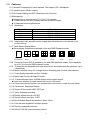
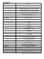
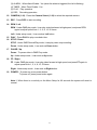
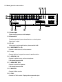
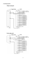
Digital Multiplex Recorder
BT-9160
User Manual
Table of Contents
1. Introduction
1-1 Safety Warning …………………………………………………………………………………
3
1-2 Features …………………………………………………………………………………………. 4
1-3 Specifications …………………………………………………………………………………... 5
2. Installation
2-1 Package contents ……………………………………………………………………………….
2-2 Connection ………………………………………………………………………………….….
2-3 Rack mount installation …………………………………………………………….…………..
2-4 RS232 /RS485 Remote protocol ……………………………………………………………..…
6
6
7
8
3. Configuration
3-1 Install HDD …………………………………………………………………………………….…
3-2 Front panel keypad ……………………………………………………………………………..
3-3 Back panel connection ………………………………………………………………………….
3-4 Menu setup ……………………………………………………………………………………….
3-5 System setup …………………………………………………………………………………….
3-6 Search setup … ………………………………………………………………………………....
3-7 TIMER setup (Schedule Time-Lapse record mode setup )………………………………….…
3-8 Record Setup …………………………………………………..………………………….…. ..
3-9 Camera setup ……….……………………………………………………………………….….
3-10 Motion Detection setup ……………..…………………………………………………….…
3-11 Event ……………………………………………………………………………………….…..
9
11
13
16
16
22
25
27
29
31
34
4. Operation
4-1 Power on …………………………………………………………………………………………
4-2 Recording ………………………………………………………………………………………...
4-3 Camera Select (1-16) ………... ……………………………………………………………….….
4-4 Select……. ………………………………………………………………………………………...
4-5 Picture in Picture………..…………………………..……………………………………………...
4-6 Zoom ………………………………………………………………………………………………
4-7 Play ……………………………………………………………………………………………….
4-8 Video Loss ………………………………………………………………………………………..
4-9 Key Lock …………………………………………………………………………………………….
35
35
36
36
37
37
37
38
38
5. Trouble shooting & appendix
5-1 Trouble shooting ………………………………………………………………………………… 39
5-2 Compatible HDD brands …………………………………………………………………...…... 40
2
1. Introduction
Thank you for choosing this high quality, Borsatec Digital Multiplex Recorder. The DMR
converts analog PAL video to digital images and records them to a removable hard disk drive.
Digitally recorded video has many advantages compared to analog video recorded on tape.
There is no need to adjust tracking. Digital video can be indexed by time schedule or events,
and you can instantly view video after selecting the time or event. You can freeze frames,
fast-forward, fast- reverse, slow-forward, and slow-reverse without image streaking or tearing. It
can be used as a replacement for both a time-lapse VCR and a multiplexer in a security
installation.
1.1 Safety Warning
All the safety and operating instructions should be read before the operation. The improper
operation may cause permanent damage.
1.1.1 Please lift and place this equipment gently.
1.1.2 Do not expose this equipment to direct sunlight.
1.1.3 Do not use this equipment near water or in contact with water.
1.1.4 Do not spill liquid of any kind on the equipment.
1.1.5 Please power down the unit before unplugging.
1.1.6 This equipment should be operated only with the power supply provided.
1.1.7 Unauthorized repair or parts substitutions may result in fire, electric shock or other
hazards.
1.1.8 Do not switch the Power On & Off within short period of time (within 3 seconds).
1.1.9 Do not attempt to service this equipment by yourself. Refer all servicing and repair to
qualified service personnel.
1.1.10 Installation should be made by qualified service personnel and should conform to all
local safety codes and regulations.
3
1.2 Features
1.2.1 Wavelet Compression Format replaces Time-Lapse VCR + Multiplexer
1.2.2 4 Audio inputs / 2Audio outputs
1.2.3 On Screen Display and RTC (Real time clock) Function
1.2.4 Multiplexing
l Support from 4 channels up to 7/ 9/ 10/ 13/ 16 channels.
l 16 channels can record or display real-time recorded images.
l 16 channels loop through terminal.
1.2.5 Resolution
Screen Modes
Full screen
4 channels
9 channels
16 channels
Resolution
704(H) x 564(V)
352(H) x 282(V)
224(H) x 188(V)
176(H) x 141(V)
1.2.6 Independent main and call monitor outputs allow simultaneous multi-camera or full
screen viewing.
1.2.7 Multi Screen Display Mode
l Below display formats are selectable in live and DMR Playback modes:
Full Screen
Quad
7 CH
9 CH
10 CH
13 CH
16 CH
1.2.8 Picture-In-Picture (PIP) is available in live and DMR playback modes, Zoom capability
up to 2 X 2 in live and DMR playback modes
1.2.9 16 channels are swappable and each channel has an independent title generator (up to
6 characters).
1.2.10 Motion detection using 15x14 target motion detection grids for each video channel.
1.2.11 Video Quality Adjustable on Each Channel
1.2.12 Alarm Input Function & Output Function
1.2.13 16 channels alarm input, ALARM display and one alarm output.
l Video loss detected on each channel can record 160 events.
1.2.14 Power-loss memory function: set up parameters will remain, in case of power failure.
1.2.15 Call Monitor: Sequence Display
1.2.16 Support 2 Removable HDD, IDE Type
1.2.17 Timer: Schedule recording
1.2.18 Display refresh rate up to 50 IPS
1.2.19 Record refresh rate up to 12 IPS
1.2.20 Quick Multiple Search by date/time, alarm, full list
1.2.21 Fast and slow playback in multiple speeds.
1.2.22 Security password protection
1.2.23 RS-232, RS-485 communication protocol
4
Specifications
Video format
Hard disk storage
PAL/CCIR
IDE type, UTMA 66 above, 2 removable HDDs supported
Record mode
Camera Input Signal
Manual / Alarm / Timer
Composite video signal 1 Vp-p 75O BNC, 16 channels
Camera Loop Back
Composite video signal 1 Vp-p 75O BNC, 16 channels
Main Monitor Output
Composite video signal 1 Vp-p 75O BNC
Call Monitor Output
Composite video signal 1 Vp-p 75O BNC
Audio input
4 audio inputs, (RCA)
Audio output
2 audio outputs, (RCA)
Motion Detect Area
15 X 14 targets per camera
Motion Detect Sensitivity
256 Levels
Video Loss Detection
Yes
Refresh Rate
50 images/sec
Recording Rate
12 images/sec
Dwell Time
Programmable (1~10 Sec)
Picture in Picture
Yes (Movable)
Key Lock
Yes
Picture Zoom
2X2 (Movable)
Camera Title
Video Adjustable
6 letters
Color/ Contrast/ Brightness Adjustable
Alarm Input
TTL input, Hi (5V), Low (GND)
Alarm Output
COM,/N.O/N.C.
Remote Control
Time Display Format
Power Source
Power Consumption
Operation Temperature
RS-232C / RS-485 (bps)
RS-232 or RS-485
YY/MM/DD, DD/MM/YY, MM/DD/YY, OFF
AC100~240V + 10% switching adaptor
<45W
10 ~ 40?
115200? 57600? 19200? 9600? 4800? 3600? 2400? 1200
Dimension (mm)
Net Weight
432(W) x 110(H) x 325(D)
5.7 kgs
Specifications are subject to change without notice.
5
2. Installation
2.1
Package contents
The package contents the following items.
l
l
l
l
l
l
Digital Multiplex Recorder
HDD cartridge x 2
Key for cartridge (Inside of HDD cartridge)
Power cord
User manual
Rack mounting kit (Optional)
2.2
Connection
2.2.1 Connect with cameras
Main Monitor
Alarm
Sensor
Video Camera
16
.. . .
2
1
.. . .
Alarm Input
RS232
AUDIO
(4 CHANNEL)
PC
Call Monitor
6
2.3
Rack mount installation
Front Angle with Rack Mount
Side View with Rack Mount
7
2.4
RS232 Remote Protocol
You can use the PC keyboard to simulate DMR keypad.
DATA: REMOTE PROTOCOL using 8 bit data? 1 start bit? 1stop bit
ACT
(FFH)
FUNCTION
KEY_MENU
KEY_SELECT
KEY_ENTER
KEY_4CUT
KEY_ZOOM
KEY_9CUT
KEY_PIP
KEY_16CUT
KEY_SLOW
KEY_REC
KEY_LEFT
KEY_UP
KEY_PLAY
KEY_DOWN
KEY_RIGHT
KEY_POWER
KEY_KEY_LOCK
C0H
CODE
0x4D
0x73
0x0D
0x61
0x5A
0x62
0x70
0x63
0x53
0x72
0x4C
0x55
0x50
0x4E
0x52
0x57
0x4B
ID
ASCII
M
s
ENTER
a
Z
b
p
c
S
r
L
U
P
N
R
W
K
FUNCTION
FUNCTION
KEY_CH1
KEY_CH2
KEY_CH3
KEY_CH4
KEY_CH5
KEY_CH6
KEY_CH7
KEY_CH8
KEY_CH9
KEY_CH10
KEY_CH11
KEY_CH12
KEY_CH13
KEY_CH14
KEY_CH15
KEY_CH16
8
STOP
(7FH)
CODE ASCII
0x31
1
0x32
2
0x33
3
0x34
4
0x35
5
0x36
6
0x37
7
0x38
8
0x39
9
0x41
A
0x42
B
0x43
C
0x44
D
0x45
E
0x46
F
0x47
G
3. Configuration
3.1
Install HDD
3.1.1 Installing Hard Drive into Cartridge
3.1.1.1. Pull the handle outwards to remove the carrier body away from the cartridge
frame.
3.1.1.2. Push the open button to slide the top cover backwards and remove.
3.1.1.3. Inside can be found the keys and fixing screws.
3.1.1.4. Insert the DC power cable and IDE cable on the HDD.
3.1.1.5. Position the HDD into carrier body and secure the HDD with the four 6#-32
screws provided.
3.1.1.6. Slide the top cover back to the carrier body by sliding it forward to secure.
3.1.1.7. Slide the carrier body back into the cartridge frame.
3.1.2 Function Settings and Operation
3.1.2.1 Power Indicator and HDD Access indicator
When power is on, the indicator will display the following message:
Item
Power Indicator
HDD Access Indicator
Indicator
Green LED
Yellow LED
3.1.3 Key lock
Status
A
B
Segment
A
B
Power
status
Security status
ON
OFF
Locked (Irremovable)
Unlocked (Removable)
You must turn key lock to “ A ” position before powering on the unit. Otherwise HDD
will not operate properly.
9
3.1.4 The Record Time is different based on Record Speed and Record Quality.
Please refer to following table.
PAL SYSTEM
IPS
Best
Record High
Quality Normal
Basic
12A
12
6
3
2
1
48hr
100hr
202hr
406hr
608hr
1216hr
60hr
126hr
254hr
506hr
760hr
1520hr
98hr
202hr
406hr
810hr
1216hr
2440hr
162hr
336hr
676hr
1350hr
2026hr
4050hr
HDD Type
240GB
Note: Above data is only a guide and actual capacities will vary depending on amount of
activity.
10
Front panel keypad
1
3
5
7
9
11
13
15
AVC 777
Digital Multiplex Recorder
2
4
6
8
10
12
14
Up
16
Left
MENU
ENTER
ZOOM
SLOW
HDD
SELECT
Right
REC
HDD
Full
ALARM
TIMER
PLAY
POWER
REC
Down
Please follow the instructions below to operate this unit.
1. Install HDD
This unit comes with two removable hard disk drive trays. Before turning on this device, you
must install at least one hard disk drive (not including in standard package), and make it ready
to operate.
(If two HDDs are set up, one should be selected as “ Master” and the other should be selected
as “ Slave”. Otherwise, please set two HDDs to Cable Select.)
2. MENU : Press MENU to enter main menu operation mode, and press administrator password
(default:0000) to access main menu.
3. ENTER : Press ENTER for confirmation.
4. ZOOM : Press ZOOM button to enlarge the main monitor picture display.
5.
: Picture in Picture. Press PIP button to enter PIP display screen.
6. SLOW : To press SLOW to slow down speed of play mode.
7. Select : Press the Select button to select the required camera (1~16) to display on full screen
mode.
8.
: 4 channels display mode
9.
: 7, 9, 10, 13 channels display mode
10.
: 16 channels display mode
11. LED Light : Under following condition, the LED Light is ON.
(1) HDD : HDD is activated
(2) HDD Full: HDD is full
11
(3) ALARM: When Alarm Enable : Yes (when the alarm is triggered, the led is flashing)
(4) TIMER: When Timer Enable : Yes
(5) PLAY: Play operation
(6) REC: Recording operation
12. CAMERA (1-16) : Press the Camera Select (1-16) to select the required camera
13. REC : Press REC to start recording.
14. REW / Left :
REW : Under DMR play mode, it can play video backward at high speed, and press REW
again to adjust speed from 1, 2, 4, 8, 16, 32 times
Left : Under setup mode , it can work as Left button.
15. PLAY : Press PLAY to play recorded video.
16. STOP / Down :
STOP : Under DMR Record/Play mode, it can play video stop recording.
Down : Under setup mode , it can work as Down button.
17. PAUSE / Up :
Pause : To pause video in DMR Play mode.
Up : Under setup mode , it can work as Up button.
18. FF / Right :
FF : Under DMR play mode, it can play video forward at high speed, and press FF again to
adjust speed from 1, 2, 4, 8, 16, 32 times.
Right : Under setup mode , it can work as Right button.
19. POWER : To power on, press power button.
To power off, press power button again.
Note 1 . When there is no activity on the Menu Setup for 60 seconds the system will revert to
normal.
12
3.3 Back panel connection
MONITOR
LOOP
AUDIO
IN
INPUT
CALL
POWER
RISK OF ELECTRIC SHOCK
DO NOT OPEN
EXTERNAL I/O
WARNING : TO REDUCE THE RISK OF ELECTRIC SHOCK,
DO NOT REMOVE COVER (OR BACK).
NO USER-SERVICEABLE PARTS INSIDE.
REFER SERVICING TO QUALIFIED
SERVICEPERSONNEL.
3.3.1 Power input
Please use the power provided adaptor.
3.3.2 External I/O
Controlled remotely by an external device or control system.
Alarm input / output.
3.3.3 75 / HI
When using Loop through function, please switch to HI.
3.3.4 VIDEO INPUT (1-16)
Connect to video source, such as camera.
3.3.5 Loop
Connect cable to Loop port to connect to another device.
3.3.6 AUDIO IN (1-4)
Connect to audio source, such as microphone.
* IPS should be set to 12A
3.3.7 AUDIO OUT (R/L)
Connect to monitor or speaker.
* IPS should be set to 12A
3.3.8 MONITOR
Connect to Main monitor
3.3.9 CALL
Connect to CALL monitor. Displays the sequenced output.
13
AUDIO
OUT
3.3.9 External I/O
25 pin com port
9 pin com port
14
PIN 1.
GND
GROUND
PIN 2. – PIN 9 , PIN 15 – PIN 22. ALARM INPUTS
When a connection is made between an alarm input and to GND (PIN 1) on the D25
connector, the DMR will start recording and the buzzer will sound.
When Menu/ Camera/ Alarm is set up to “Low”: When alarm input signal is “ Low ”,
the unit starts to record and sounds buzzer.
When Menu/ Camera/ Alarm is set up to “High”: When alarm input signal is “ High ”,
the unit starts to record and sounds buzzer.
PIN 10. NO Connection
PIN 11/23. RS232-TX / RS232-RX
DMR can be controlled remotely by an external device or control system, such as a
control keyboard, using RS-232 serial communications signals.
PIN 12/24. RS485-A / RS485-B
DMR can be controlled remotely by an external device or control system, such as a
control keyboard, using RS485 serial communications signals.
PIN 13/25. EXTERNAL ALARM NO
Under normal operation COM is disconnected from NO. But when an Alarm is
triggered, COM connects with NO.
PIN 14. NO CONNECTION
15
3.4 Menu setup
Press ”MENU” to enter main menu. A password
is required to access main menu. Press “Right”
“Left” to move digit, and Press ”Up” “Down” to
select number. Press ”ENTER” button to
confirm password.
PASSWORD : 0000
Ex.: Password : 0000 (Default : 0000)
After keying in the correct password and
confirming by pressing ”ENTER” button, the
screen will show the following options.
SEARCH ------- Find recorded list
TIMER -------- Scheduling Record
RECORD------- Record Mode Setup
CAMERA ------- Camera Channel Setup
SYSTEM ------- System Setup
EVENT -------- Event List
(MENU)
? SEARCH
TIMER
RECORD
CAMERA
SYSTEM
EVENT
3.5 System setup
Press ”MENU” to enter the main menu. It is
necessary to enter the password to access the
main menu. Press “Right” “Left” to move digit,
and Press ”Up” “Down” to select number.
Press ”ENTER” button to confirm password.
PASSWORD : 0000
Ex.: PASSWORD : 0000 (Default : 0000)
After keying in the correct password, and
confirming by pressing the ”ENTER” button,
the screen will show the following options.
SEARCH ------- Find recorded list
TIMER -------- Scheduling Record
RECORD------- Record Mode Setup
CAMERA ------- Camera Channel Setup
SYSTEM ------- System Setup
EVENT -------- Event List
16
(MENU)
? SEARCH
TIMER
RECORD
CAMERA
SYSTEM
EVENT
Press ”Up” “Down” to choose SYSTEM setup
(Menu)
SEARCH
TIMER
RECORD
CAMERA
? SYSTEM
EVENT
SEARCH
TIMER
RECORD
CAMERA
? SYSTEM
EVENT
Press ”ENTER” to confirm SYSTEM setup, and the screen will show the following options.
(SYSTEM)
? AUDIO INPUT : 1
INT AUDIBLE ALARM : ON
EXT AUDIBLE ALARM : ON
ALARM DURATION : 10 SEC
DWELL TIME : 02 SEC
MESSAGE LATCH : NO
TITLE DISPLAY :ON
TIME DISPLAY : Y/M/D
2003-JAN-02(THU) 17:37:09
NEW PASSWORD : XXXX
CLEARD HDD : NO
SYSTEM RESET : NO
REMOTE MODE : RS-232
BAUD RATE :
9600
REMOTE ID : 000
3.5.1 AUDIO INPUT setup:
This setting allows the user to set the AUDIO INPUT. User can choose one
of 4 channels to record.
3.5.1.1 Press ”Up” “Down” to choose AUDIO INPUT :
3.5.1.2 Press ”ENTER” button to confirm AUDIO INPUT
3.5.1.3 Press ”Up” “Down” to choose the AUDIO INPUT : 1~4
3.5.1.4 Press ”MENU” to exit and confirm the current operation.
3.5.1.5 Press ”MENU” again to exit and close SYSTEM setup mode.
17
3.5.2 INT AUDIBLE ALARM setup:
This setting allows the user to set the INTERNAL AUDIBLE ALARM. The alarm will be
trigged by an event occurrence when the setting is ON.
3.5.2.1 Press ” Up” or “ Down” to choose INT AUDIBLE ALARM
3.5.2.2 Press ” ENTER” button to confirm INT AUDIBLE ALARM
3.5.2.3 Press ” Up” or “ Down” to choose the INT AUDIBLE ALARM : ON/OFF
ON: Internal Buzzer ON
OFF: Internal Buzzer OFF
3.5.2.4 Press ” MENU” to exit and confirm the current operation.
3.5.2.5 Press ” MENU ” again to exit and close SYSTEM setup mode.
3.5.3 EXT AUDIBLE ALARM setup:
This setting allows the user to set the EXTERNAL AUDIBLE ALARM. The alarm will be
trigged by an event occurrence when the setting is ON.
3.5.3.1 Press ” Up” or “ Down” to choose EXT AUDIBLE ALARM
3.5.3.2 Press ” ENTER” button to confirm EXT AUDIBLE ALARM
3.5.3.3 Press ” Up” or “ Down” to choose the EXT AUDIBLE ALARM: ON/OFF
ON: External Buzzer ON
OFF: External Buzzer OFF
3.5.3.4 Press ” MENU” to exit and confirm the current operation.
3.5.3.5 Press ” MENU” again to exit and close SYSTEM setup mode.
3.5.4 ALARM DURATION Setup option:
This setting allows the user to set the ALARM DURATION. i.e. the length of time the
buzzer will sound on alarm activation.
3.5.4.1 Press ” Up” or “ Down” to choose ALARM DURATION setup.
3.5.4.2 Press ” ENTER” to confirm ALARM DURATION setup.
3.5.4.3 Press ” Up” or “Down” to choose ALARM DURATION setup
10 SEC, 15 SEC, 20 SEC, 30 SEC, 1MIN, 2MIN, 3 MIN, 5 MIN, 10 MIN, 15 MIN,
30 MIN, ALWAYS.
3.5.4.4 Press ” MENU” to exit and confirm the current operation.
3.5.4.5 Press ” MENU” again to exit and close SYSTEM setup mode.
18
3.5.5 DWELL TIME setup
This setting allows the user to set the DWELL TIME. DWELL TIME is the length of time
that each channel is sequentially shown on the CALL monitor output.
3.5.5.1 Press ” Up” or “ Down” to choose DWELL TIME setup.
3.5.5.2 Press ” ENTER” to confirm DWELL TIME setup.
3.5.5.3 Press ” Up” or “ Down” to choose DWELL TIME setup.
01~10 SEC.
3.5.5.4 Press ” MENU” to exit and confirm the current operation.
3.5.5.5 Press ” MENU” again to exit and close SYSTEM setup mode.
3.5.6 MESSAGE LATCH setup
This setting allows the user to decide whether the External Alarm graph is displayed on
the monitor or not.
3.5.6.1 Press ” Up” or “ Down” to choose MESSAGE LATCH setup
3.5.6.2 Press ” ENTER” button to confirm MESSAGE LATCH setup
3.6.6.3 Press ” Up” or “ Down” to choose the MESSAGE LATCH : ON/OFF
ON : Message latch ON
OFF : Message latch OFF
3.6.6.4 Press ” MENU” to exit and confirm the current operation.
3.6.6.5 Press ” MENU” again to exit and close SYSTEM setup mode.
3.5.7 TITLE DISPLAY setup
This setting allows the user to set whether the title is shown on the monitor or not.
3.6.7.1 Press ” Up” or “ Down ” to choose TITLE DISPLAY setup
3.6.7.2 Press ” ENTER” button to confirm TITLE DISPLAY setup
3.6.7.3 Press ” Up” or “ Down ” to choose TITLE DISPLAY : ON/OFF
ON : Title Display ON
OFF : Title Display OFF
3.6.7.4 Press ” MENU ” to exit and confirm the current operation.
3.6.7.5 Press ” MENU ” again to exit and close SYSTEM setup mode.
19
3.5.8 TIME DISPLAY format setup
This setting allows the user to set the time format on the monitor.
3.5.8.1 Press ” Up” or “ Down ” to choose TIME DISPLAY setup.
3.5.8.2 Press ” ENTER ” to confirm TIME DISPLAY setup.
3.5.8.3 Press” Up ” or “ Down ” to choose TIME DISPLAY setup.
OFF, Y/M/D, M/D/Y, D/M/Y.
3.5.8.4 Press ” MENU ” to exit and confirm the current operation.
3.5.8.5 Press ” MENU ” again to exit and close SYSTEM setup mode.
3.5.9 TIME setup:
This setting allows the user to set time on the monitor.
3.5.9.1 Press ” Up ” or “ Down ” to choose date display
3.5.9.2 Press ” ENTER ” to confirm date display format.
3.5.9.3 Press ” Up ” or “ Down ” to choose the correct Date & Time, and press
“ Right ” or “ Left ” to move digit location.
3.5.9.4 Press ” MENU ” to exit and confirm the current operation.
3.5.9.5 Press ” MENU ” again to exit and close SYSTEM setup mode.
3.5.10 NEW PASSWORD : XXXX setup: (Default password : 0000)
This setting allows the user to set the new password.
3.5.10.1 Press ” Up ” or “ Down ” to choose NEW PASSWORD : XXXX setup.
3.5.10.2 Press ” ENTER ” to confirm NEW PASSWORD : XXXX setup.
3.5.10.3 Press ” Up ” or “ Down ” to choose number, and press“ Right ” or “ Left ” to
move digit location.
3.5.10.4 Press ” MENU ” to exit and confirm the current operation.
3.5.10.5 Press ” MENU ” again to exit and close SYSTEM setup mode.
20
3.5.11 CLEAR HDD setup
This setting allows the user to clear the HDD.
3.5.11.1 Press ” Up ” or “ Down ” to choose CLEAR HDD setup.
3.5.11.2 Press ” ENTER ” to confirm CLEAR HDD setup.
3.5.11.3 Press ” Up ” or “ Down ” to choose CLEAR HDD setup YES or NO.
YES: Confirm to clear HDD, and screen will show the following;
ALL DATA IN HDD
WILL BE CLEARED
ARE YOU SURE?
(? : NO ? : YES )
Press“ ? ” to clear HDD
NO: Confirm not to clear HDD.
3.5.11.4 Press ” MENU ” to exit and confirm the current operation.
3.5.11.5 Press ” MENU ” again to exit and close SYSTEM setup mode.
3.5.12 SYSTEM RESET setup
This setting allows the user to reset the system.
3.5.12.1 Press ” Up ” or “ Down ” to choose SYSTEM RESET setup.
3.5.12.2 Press ” ENTER” to confirm SYSTEM RESET setup.
3.5.12.3 Press ” ” Up ” or “ Down ” to choose SYSTEM RESET Yes or No
YES: To confirm System Reset (load default system reset)
NO: Confirm not to System Reset
3.5.12.4 Press ” MENU ” to exit and confirm the current operation.
3.5.12.5 Press ” MENU ” again to exit and close SYSTEM setup mode.
3.5.13 REMOTE MODE setup
This setting allows the user to set the remote mode.
3.5.13.1 Press ” Up ” or “ Down ” to choose REMOTE MODE setup
3.5.13.2 Press ” ENTER ” to confirm REMOTE MODE setup
3.5.13.3 Press ” Up ” or “ Down ” to choose Interface for REMOTE MODE setup
RS-232: Use RS-232 interface
RS-485: Use RS-485 interface
3.5.13.4 Press ” MENU ” to exit and confirm the current operation.
3.5.13.5 Press ” MENU ” again to exit and close SYSTEM setup mode.
21
3.5.14 Remote protocol Baud Rate setup
This setting allows the user to set the remote protocol baud rate.
3.5.14.1 Press ” Up ” or “ Down ” to choose Baud Rate setup.
3.5.14.2 Press ” ENTER ” to confirm
3.5.13.3 Press ” Up ” or “ Down ” to choose BAUD RATE setup
115200? 57600? 19200? 9600? 4800? 3600? 2400? 1200
3.5.14.4 Press ” MENU ” to exit and confirm the current operation.
3.5.14.5 Press ” MENU ” again to exit and close SYSTEM setup mode.
3.5.15 Remote protocol ID setup:
This setting allows the user to control different DMR’s by setting RS232 remote protocol.
ID number can be set from 000 to be 999.
3.5.15.1 Press ” Up ” or “ Down ” to choose ID setup.
3.5.14.2 Press ” ENTER ” to confirm ID setup
3.5.15.3 Press ” Up ” or “ Down ” to set numerical number, from 000 ~ 255
3.5.15.4 Press ” MENU ” to exit and confirm the current operation.
3.5.15.5 Press ” MENU ” again to exit and close SYSTEM setup mode.
3.6
SEARCH setup
Press ”MENU” to enter main menu. It is
necessary to enter the password to access the
main menu. Press “ Right ” or “ Left ” to move
digit, and to press Up ” or “ Down ” to select
number. Press ”ENTER” button to confirm
password.
PASSWORD: 0000
Ex.: Password: 0000 (Default: 0000)
After keying in the correct password, and
confirming by pressing ”ENTER” button, screen
will show the following options;
SEARCH ------- Find recorded list
TIMER -------- Scheduling Record
RECORD------- Record Mode Setup
CAMERA ------- Camera Channel Setup
SYSTEM ------- System Setup
EVENT -------- Event List
22
(MENU)
? SEARCH
TIMER
RECORD
CAMERA
SYSTEM
EVENT
3.6.1 LAST RECORD for recorded video
Press ” Up ” or “ Down ” to choose LAST
RECORD item. The following screen will be
displayed. Press “ENTER” to confirm LAST
RECORD.
?
LAST RECORD
FULL LIST
ALARM LIST
TIME SEARCH
3.6.2 FULL LIST for recorded video
Press ” Up ” or “ Down ” to choose Full List
item. The following screen will be displayed.
?
Press “ ENTER ” to confirm Full List, and the
LAST RECORD
FULL LIST
ALARM LIST
TIME SEARCH
? M 2002-JAN-01 01:02:03 M-HDD
following screen will be displayed.
M 2002-JAN-01 01:02:03 M-HDD
Press ” Up ” or “ Down ” to choose the desired
A 2002-JAN-01 01:02:03 M-HDD
recorded event (There will only be eight shown
T 2002-JAN-01 01:02:03 M-HDD
on one page.), and press “Right ” or “ Left ” to
T 2002-JAN-01 01:02:03 S-HDD
change the pages.
M 2002-JAN-01 01:02:03 S-HDD
Press “ENTER” to Play selected recorded video
? : PAGE UP? : PAGE DOWN
M : Manual Record time / A : Alarm Record time
T : Timer Record time
M-HDD : Storage in Master HDD
S-HDD : Storage in Slave HDD
23
3.6.3 ALARM LIST for recorded video
Press ” Up ” or “ Down ” to choose ALARM
LIST. The following screen will be displayed.
?
Press “ENTER” to confirm FULL LIST, and
the following screen will be displayed.
Press ” Up ” or “ Down ” to choose the
desired recorded event (There will only be
eight shown on one page.), and press “ Left ”
or “ Right” to change the pages.
Press “ENTER” to Play selected recorded
video
LAST RECORD
FULL LIST
ALARM LIST
TIME SEARCH
? A 2002-JAN-01 01:02:03 M-HDD
A 2002-JAN-01 01:02:03 M-HDD
A 2002-JAN-01 01:02:03 M-HDD
A 2002-JAN-01 01:02:03 M-HDD
A 2002-JAN-01 01:02:03 S-HDD
A 2002-JAN-01 01:02:03 S-HDD
? : PAGE UP? : PAGE DOWN
3.6.3 TIME SEARCH for recorded video
Press” Up ” or “ Down ” to choose Time Search
item. The following screen will be displayed.
LAST RECORD
FULL LIST
ALARM LIST
? TIME SEARCH
Press “ENTER” to confirm Full List, and the
screen will be as displayed on the right.
Press ” Up ” or “ Down ” to choose the
desired date & hour for recorded event , and
press “ Left ” or “ Right ” to change the
location.
Press “ENTER” to play select time recorded
video. If there is no record in the database,
the screen will display “ NOT FOUND ” .
24
PLAY TIME: 2002-JAN-01 18
3.7
TIMER setup (Schedule Time-Lapse record mode setup )
3.7.1 Enter TIMER setup
Press ”MENU” to enter the main menu. It is
necessary to enter the password to access
the main menu. Press “ Left ” or “Right ” to
move digit, and press ” Up “ or “ Down ” to
select number. Press ”ENTER” button to
confirm password.
PASSWORD : 0000
Ex.: PASSWORD : 0000 (Default : 0000)
After keying in the correct password, and
confirming by pressing ”ENTER” button, the
following screen will be displayed. SEARCH
------- find recorded list
TIMER ------- scheduling Record
RECORD------- Record Mode Setup
CAMERA ------- Camera Channel Setup
SYSTEM ------- System Setup
EVENT -------- Event List
(Menu)
SEARCH
? TIMER
RECORD
CAMERA
SYSTEM
EVENT
(TIMER)
Select TIMER item, and press “ENTER” button to
confirm TIMER Record setup mode. The following
screen will be displayed.
25
DAY START END QUALITY
DAILY 00:00 00:00 BEST
DAILY 00:00 00:00 BEST
DAILY 00:00 00:00 BEST
DAILY 00:00 00:00 BEST
DAILY 00:00 00:00 BEST
DAILY 00:00 00:00 BEST
DAILY 00:00 00:00 BEST
DAILY 00:00 00:00 BEST
TIMER ENABLE : NO
IPS
15A
15A
15A
15A
15A
15A
15A
15A
3.7.2 TIMER setup:
3.7.2.1 Press ” ENTER ” to confirm TIMER setup.
3.7.2.2 Press ” Up ” or “ Down ” to choose the Timer Record day
Daily : Everyday
MON : Monday
TUE : Tuesday
WED : Wednesday
THU : Thursday
FRI : Friday
SAT : Saturday
SUN : Sunday
MO-FR : Monday to Friday
SA-SU : Saturday & Sunday
JAN-01 : Special Date
OFF : Not activated
3.7.2.3 Press “ Left ” or “ Right ” to move to START record time 00:00 (HH:MM)
Press ” Up ” or “ Down ” to change START record time numerical digit
3.7.2.4 Press “ Left ” or “ Right ” to move to END record time 00:00 (HH:MM)
Press ” Up ” or “ Down ” to change END record Time numerical digit
3.7.2.5 Press “ Left ” or “ Right ” to move to QUALITY
Press” Up ” or “ Down ” to choose options of
BEST, HIGH, NORMAL, BASIC
3.7.2.6 Press “ Left ” or “ Right ” to move to Record IPS (Images Per Second)
Press” Up ” or “ Down ” to choose options of
PAL- 12A? 12? 6? 3? 2? 1
3.7.2.7 Press ”MENU” to confirm the current operation, and move to the next
Timer Record setup.
3.7.2.8 Press “ Left ” or “ Right ”to move location to Timer Enable: Yes or No setup
YES : To confirm Timer Enable: Scheduling Timer Record function
NO : To confirm no Timer Enable: No Scheduling Timer Record function
3.7.2.9 Press ” MENU ” to exit and confirm the current operation.
3.7.2.10 Press again ” MENU ” to exit and close TIMER setup mode.
26
3.8 RECORD MODE setup
3.8.1 To Enter “ Record “ setup
Press ”MENU” to enter the main menu. It is necessary
to enter the password to access the main menu. Press
“ Left ” or “ Right ” to move digit, and press ” Up ” or
“ Down ” to select number. Press ” ENTER ” button to
confirm password.
PASSWORD: 0000
Ex.: PASSWORD: 0000 (Default: 0000)
After keying in the correct password, and confirming by
pressing ” ENTER ” button, the following screen will be
displayed.
SEARCH ------- find recorded list
TIMER ------- scheduling Record
RECORD------- Record Mode Setup
CAMERA ------- Camera Channel Setup
SYSTEM ------- System Setup
EVENT -------- Event List
(MENU)
SEARCH
TIMER
? RECORD
CAMERA
SYSTEM
EVENT
To choose Record item, and press “ ENTER ” to enter
Record mode. The following screen will be displayed.
(RECORD)
? HDD OVERWRITE: NO
RECORD IPS: 15A
RECORD QUALITY : NORMAL
ALARM REC IPS: 15A
ALARM REC QUALITY : NORMAL
27
3.8.2 HDD OVERWRITE setup :
3.8.2.1 Press ” ENTER” to confirm HDD OVERWRITE setup.
3.8.2.2 Press ” Up ” or “ Down ” to choose HDD OVERWRITE.
NO : When HDD is full it will stop recording
YES : When HDD is full it will overwrite the HDD recording
3.8.2.3 Press ” MENU ” to exit and confirm the current operation.
3.8.2.4 Press again ” MENU ” to exit and close HDD OVERWRITE setup mode.
3.8.3 RECORD IPS setup:
3.8.3.1 Press ” ENTER” to confirm RECORD IPS setup.
3.8.3.2 Press ” Up ” or “ Down ” to choose IPS record speed.
PAL- 12A? 12? 6? 3? 2? 1
3.8.3.3 Press ” MENU ” to exit and confirm the current operation.
3.8.3.4 Press ” MENU ” again to exit and close RECORD IPS setup mode.
3.8.4 RECORD QUALITY setup
3.8.4.1 Press ” ENTER ” to confirm Record Quality setup.
3.8.4.2 Press” Up ” or “ Down ” to choose Record Quality level.
BEST, HIGH, NORMAL, BASIC
3.8.4.3 Press ” MENU ” to exit and confirm the current operation.
3.8.4.4 Press ” MENU ” again to exit and close RECORD QUALITY setup mode.
3.8.5 ALARM REC IPS setup
3.8.5.1 Press ” ENTER ” to confirm ALARM REC IPS setup.
3.8.5.2 Press ” Up ” or “ Down ” to choose ALARM REC IPS record speed.
PAL- 12A? 12? 6? 3? 2? 1
3.8.5.3 Press ” MENU ” to exit and confirm the current operation.
3.8.5.4 Press again ” MENU ” to exit and close ALARM REC IPS setup mode.
3.8.6 ALARM REC QUALITY setup
3.8.6.1 Press ” ENTER ” to confirm ALARM REC QUALITY setup.
3.8.6.2 Press” Up ” or “ Down ” to choose ALARM REC QUALITY level.
BEST, HIGH, NORMAL, BASIC
3.8.6.3 Press ” MENU ” to exit and confirm the current operation.
3.8.6.4 Press again ” MENU ” to exit and close ALARM REC QUALITY setup mode.
28
3.9 CAMERA setup
Press ”MENU” to enter main menu. It is necessary
to enter password to access the main menu. Press
“ Left ” or “ Right ” to move digit, and to press ”
Up ” or “ Down ” to select number. Press ”
ENTER ” button to confirm password.
PASSWORD : 0000
Ex.: Password : 0000 (Default : 0000)
After keying in the correct password, and confirming
by pressing ” ENTER ” button, Following screen will
be displayed.
SEARCH ------- find recorded list
TIMER ------- Scheduling Record
RECORD------- Record Mode Setup
CAMERA ------- Camera Channel Setup
SYSTEM ------- System Setup
EVENT -------- Event List
(MENU)
SEARCH
TIMER
RECORD
? CAMERA
SYSTEM
EVENT
CAMERA setup
?
TITLE
---- 01
---- 02
---- 03
---- 04
---- 05
---- 06
---- 07
---- 08
---- 09
---- 10
---- 11
---- 12
---- 13
---- 14
---- 15
---- 16
DWELL
ON
ON
ON
ON
ON
ON
ON
ON
ON
ON
ON
ON
ON
ON
ON
ON
5
5
5
5
5
5
5
5
5
5
5
5
5
5
5
5
5
5
5
5
5
5
5
5
5
5
5
5
5
5
5
5
29
5
5
5
5
5
5
5
5
5
5
5
5
5
5
5
5
ALARM RECORD
LOW
EVENT
LOW
EVENT
LOW
EVENT
LOW
EVENT
LOW
EVENT
LOW
EVENT
LOW
EVENT
LOW
EVENT
LOW
EVENT
LOW
EVENT
LOW
EVENT
LOW
EVENT
LOW
EVENT
LOW
EVENT
LOW
EVENT
LOW
EVENT
3.9.1 TITLE :It allows assignment of a title to each camera input. Initially each title is the camera’s
number 01 -16
3.9.1.1 Press” Up ” or “ Down ” : Select channel in the Channel setup
3.9.1.2 Press ENTER: Confirm the channel
3.9.1.3 Press “ Left ” or “ Right ” : Select the location of title (6 characters maximum)
3.9.1.4 Press ” Up ” or “ Down ” : Select the characters for display (0~9, A~Z,-, :, (, ), )
3.9.1.5 Press “ MENU ” : Confirm and exit the title setting
3.9.1.6 Press “ MENU ” : Exit the Channel setup
3.9.2 DWELL: to set up auto switching channel
3.9.2.1 Press ” Up ” or “ Down ” : Select channel in the Channel setup
3.9.2.2 Press “ ENTER ”: Enter the channel setup
3.9.2.3 Press “ Left ” or “ Right ” : Select DWELL on the screen
3.9.2.4 Press ” Up ” or “ Down ” : Select ON/OFF on the screen
3.9.2.5 Press “ MENU ” : Confirm and exit the dwell setting
3.9.2.6 Press “ MENU ” : Exit the channel setup
3.9.3
(Brightness) /
(Contrast) /
(Color): video adjustment of each channel
3.9.3.1 Press ” Up ” or “ Down ” : Select channel in the Channel setup
3.9.3.2 Press “ENTER” Enter the channel setup
3.9.3.3 Press “ Left ” or “ Right ” : Select brightness/contrast/color on the screen
3.9.3.4 Press ” Up ” or “ Down ” : Set up 0~9 on the screen.
3.9.3.5 Press “MENU ” : Confirm and exit the brightness/contrast/color setting.
3.9.3.6 Press “MENU”: Exit the channel setup
3.9.4 ALARM
3.9.4.1 Press ” Up ” or “ Down ” : Select channel in the Channel setup
3.9.4.2 Press “ENTER” Enter the cannel setup
3.9.4.3 Press “ Left ” or “ Right ” : Select ALARM on the screen
3.9.4.4 Press ” Up ” or “ Down ” : Select LOW/OFF/HIGH for alarm priority.
3.9.4.5 Press “MENU”:” Confirm and exit the alarm setting.
3.9.4.6 Press
“MENU”:” Exit the channel setup
30
3.9.5 RECORD
3.9.5.1 Press ” Up ” or “ Down ” : Select channel in the Channel setup
3.9.5.2 Press “ENTER” : Enter the channel setup
3.9.5.3 Press ” “ Left ” or “ Right ” : Select Record on the screen.
3.9.5.4 Press ” Up ” or “ Down ” : Select DMR record method as below (DMR will only record
the channel which has been set up for EVENT/ NORMAL/ OFF)
EVENT : when alarm input is triggered, the DMR will record the alarming channel
more frequently. For example : the DMR normal record method is
1-2-3-4-5-……-16. In Event mode, when CH01 is triggered, the record method will
become
1-2-1-3-1-4-1-5-…-16.
NORMAL : when external alarm is on, the DMR will record normally as set up.
OFF : the DMR will not record
3.9.5 Press “ MENU ” : Confirm and exit the record setting
3.9.6 Press “ MENU ”: Exit the channel setup
3.10
MOTION DETECTION setup
3.10.1 Press “ MENU “ to enter the menu set up, then “ Down” to CAMERA setup,
Press “ENTER” twice to enter the Motion Detection Setup .
3.10.2 Each screen displays the current camera picture overlaid with the motion targets (as
Figure 1). You can push the button “ Left ” or “ Right ”, ” Up ” or “ Down ” to adjust
motion detection in ON or OFF.
3.10.3 The targets on each motion setup can be turned to ON or OFF individually by row. To set
up targets, using the following front panel buttons:
3.10.3.1 Press ‘ENTER” to confirm the channel
3.10.3.2 Press “ENTER” to enter motion mode
3.10.3.3 ? Up -- moves the target cursor up one row at a time.
3.10.3.4 ? Down -- moves the target cursor down one row at a time.
3.10.3.5 ? Left -- moves the target cursor left one column at a time.
3.10.3.6 ? Right -- moves the target cursor right one column at a time.
3.10.3.7 Press “ENTER” to turn the target cursor ON
Press “ENTER” again to turn the target cursor OFF
3.10.3.8 Camera Select (1-15) -– toggles the corresponding target on the cursor line ON or
OFF. (Figure 1) There are only 15 targets in a row, therefore; only Camera
Selected (1-15) can be operated.
3.10.3.9 Zoom – turns all targets in the current row ON or OFF. (Figure 1-2)
3.10.3.10 PIP – turns all targets on the screen ON or OFF. (Figure 1-3)
31
3.10.4 Press “ SLOW “ button to setup the Sensitivity list up to 255
Press “ REC “ button to setup the Sensitivity list down to 000
Sensitivity value is related to motion and brightness change.
Low value (as 001) means higher sensitivity on motion and brightness change.
High value (as 255) means lower sensitivity on motion and brightness change.
User can choose the suitable sensitivity value in different locations.
The default value is set on 32.
Note:
If Motion Detection is set, and when activated, there will be two actions as follows:
1). Live video - the motion detected camera(s) will be scanned more frequently, if the Video
setup is for 16 cameras, the sequence to scan the cameras are from 1st, 2nd, 3rd... until 16th
camera, but if the motion is detected on Camera #1, the sequence to scan #1 camera will be
more frequently. It will be scanning as 1st, 2nd, 1st, 3rd, 1st, 4th...1st, 16th.
The motion-detected camera will be scanned more frequently, which will be one after another
camera been detected. If the 2nd and 3rd camera both motion detection are activated, they will
be scanning as 1st, 2nd, 3rd, 2nd, 2nd, 3rd, 3rd, 2nd, 3rd, 4th, 2nd, 3rd....3rd, 16th, 2nd, 3rd
and vice versa.
2). Recorded Video - more frequently video will be recorded for the motion detected cameras,
the function is the same as Live video in the above mentioned.
Basically, the motion detection will only change the scanning sequence while in live mode or in
Record mode. It doesn’t show any sign on the monitor and it cannot automatically change the
mode from Standby Mode to Record Mode.
Figure 1
1
2
MOTION DETECTION SETUP
3
4
5
6
7
8
9
10
11
12
13
14
15
032
--
--
--
--
--
--
--
--
--
32
--
--
--
--
--
--
Figure 1-1
MOTION DETECTION SETUP – 1~16
1
4
2
3
5
6
7
8
9
10
11
12
13
14
15
032
--
--
--
--
--
--
--
--
--
--
--
--
Figure 1-2
MOTION DETECTION SETUP – LINE
1
4
2
3
5
6
7
8
9
10
11
12
--
13
--
14
--
15
032
--
--
--
Figure 1-3
1
2
--
--
--
--
--
--
--
--
--
--
--
--
MOTION DETECTION SETUP – ALL
3
4
5
6
7
8
9
10
11
12
13
14
15
032
--
--
--
--
--
--
--
--
--
33
--
--
--
--
--
--
3.11 Event
3.11.1 Enter “ Event “ list
Press ”MENU” to enter main menu. It is
necessary to enter the password to access the
main menu. Press “ Left ” or “ Right ” to
move digit, and to press” Up ” or “ Down ” to
select number. To press ”ENTER” button to
confirm password.
PASSWORD : 0000
Ex.: Password: 0000 (Default: 0000)
After keying in the correct password, and
confirming by pressing ”ENTER” button, The
following screen will be displayed.
SEARCH ------- Find recorded list
TIMER -------Scheduling Record
RECORD------- Record Mode Setup
CAMERA ------- Camera Channel Setup
SYSTEM ------- System Setup
EVENT -------- Event List
Press “ENTER” to confirm Full List, and the
screen will be displayed as shown on the
right.
Press ” ” Up ” or “ Down ” to choose desired
recorded event (Only eight recorded events
will be shown on a single page), and press
“ Left ” or “ Right ” to change the pages.
Press “ENTER” to Play selected recorded
video
(MENU)
SEARCH
TIMER
RECORD
CAMERA
SYSTEM
? EVENT
M–HDD WARNING 2002-JAN-01 03:00:00
M–HDD LOSS
2002-JAN-01 03:00:00
M–HDD ERROR 2002-JAN-01 03:00:00
S–HDD WARNING 2002-JAN-01 03:00:00
HDD FULL
2002-JAN-01 03:00:00
SYSTEM ERROR 2002-JAN-01 03:00:00
----02 VLOSS
2002-JAN-01 03:00:00
----03 ALARM
2002-JAN-01 03:00:00
? : PAGE UP ? : PAGE DOWN? +? : CLEAR
M-HDD WARNING: Master HDD might be failed.
M-HDD LOSS: Master HDD does not exist. Now user can use the other HDD.
M-HDD ERROR: Master HDD might be error
S-HDD WARNING: Slave HDD might be failed
S-HDD LOSS: Slave HDD does not exist. Now user can use the other HDD.
S-HDD ERROR: Slave HDD might be error
HDD FULL: HDD is full
SYSTEM ERROR: System might be failed
----02 VLOSS: Channel: 2 Video loss
----03 ALARM: Channel: 3 External I/O Alarm have triggered
POWER RESTORE : Power restore
34
4. Operation
4.1
Power on
Before turning on the power, make sure the HDD has been locked, and the POWER LED is
red. After pressing the POWER button, the POWER LED will turn to orange colo ur, then all
other LED lights will turn to RED colo ur except the LED for the HDD. OSD screen will display
“HDD Detecting”, Power on period will take approximately 15 to 20 seconds. The screen will
then show HDD Master and Slave connected. After setup period of DMR the POWER LED will
turn to green colour. (You can set up HDD to be Master or Slave by jumper setting on HDD.)
4.2
Recording
Your DMR offers a variety of flexible recording modes. You can set it up to record continually,
scheduled time, or by record events, and you can also set up recording speed and
resolution. You can set these options by selecting MENU and System before recording.
Under the recording status, if power is stopped accidentally, recorded video will still store in
the HDD after power on. DMR will continue with original recording setup after power return.
There are 3 record modes for DMR: Alarm Record, Timer Record, and Manual Record. All
Record Mode descriptions are as follows;
4.2.1 Alarm Record
When DMR is triggered by alarm input, it will start to record immediately. The following
screen will be displayed.
A : Alarm trigger
OW : HDD Over Write
032GB : If the OW location shows 32GB, it
means that 32 GB HDD is left for video
recording. (1 HDD installed)
001GB : If the OW location shows 32GB, it means
032GB that 32 GB left in slave HDD and 1 GB
left in the aster HDD for video
recording. (2 HDD installed)
35
2002 – JAN –01 01:02:03
A?OW
4.2.2 Timer Record
DMR will follow Timer setup to record, and the recording speed and quality will be as the
timer recording mode setup in main menu.
The screen will be as displayed on the right.
T : Timer record
OW : HDD Over Write
032GB : If the OW location shows 32GB, it
means that 32 GB HDD left for video
recording. (1 HDD installed)
001GB : If the OW location shows 32GB, it means
032GB that 32 GB left in slave HDD and 1 GB
left in master HDD for video recording.
(2 HDD installed)
2002 – JAN –01 01:02:03
T?OW
4.2.3 Manual Record
You can press “REC” to start recording immediately. The recording speed & quality will
be as the “Record” recording mode setup in main menu.
The following screen will be displayed.
M : Manual record
OW : HDD Over Write
032GB : If the OW location shows 32GB, it
means that 32 GB HDD left for video
recording.
001GB : If the OW location shows 32GB, it
032GB means that 32 GB left in slave HDD
and 1 GB left in master HDD for video
recording. (2 HDD installed)
4.3
2002 – JAN –01 01:02:03
M?OW
Camera Select (1-16)
Press Camera Select Button (1-16) to select the camera to display in full screen mode.
4.4
Select
This setting allows the user to get the ideal view size.
4.4.1. Press
,,
,
button to make different view size.
4.4.2 Press “ Select ” then “ Left ” or “ Right ” button to locate the desired position.
4.4.3 Press “ Camera Select (1-16) “ to select the appointed camera.
4.4.4 Press “ Menu “ to exit.
36
4.5 Picture in Picture (PIP)
Press PIP
button to enter PIP display screen. The PIP format displays a full screen
“background” picture with a 1/16 size screen ‘insert”.
4.5.1 Press
button to display the last selected PIP mode. ID - the camera numbers
appear on the bottom of the screen
4.5.2 To change the selection press SELECT. When the camera ID flashes a new camera
can be selected by pressing the individual camera button. This applies to both the main
picture and the insert.
4.5.3 Press “ Menu “ to exit
4.6 Zoom
Press ZOOM button to enlarge the display of main picture. It displays zoom picture on main
picture and a small window inserted. The inserted window contains a movable 1/4 view size
of the appointed camera.
4.6.1 Press the appointed “ Camera Select (1-16) “.
4.6.2 Press “ Zoom “ button to be zoom mode.
4.6.3 Press the “Zoom ” button again to move the zoom pointer.
4.6.4 Press “ Camera Select (1-16) “ to exit.
4.7 Play
Press “ PLAY ” then DMR will enter the Play mode; it will show the last record.
4.7.1 Fast Forward (F.F. ) & Fast Rewind (F.R.)
4.7.1.1 Press “ PLAY ” and press ” ? ? ” for fast forward searching. Press once ” ? ? ” to
get speed for 2X. Press twice “? ? ” to get speed for 4X,. …And the maximum
speed can be 32X.
4.7.1.2 Press “ PLAY ” then Press ”? ? ” for fast rewind searching. Press
once “? ? ” to get speed for 2X. Press twice “? ? ” to get speed for 4X, … and
the maximum speed can be 32X.
4.7.2 Slow Forward (S.F.) & Slow Rewind (S.R.)
4.7.2.1 Press “ PLAY ” then press ” SLOW ” for slow play, Press once “? ? ” for slow
forward speed 1/2X. and press twice “? ? ” speed for 1/4X, ….the minimum slow
speed can be 1/32X.
4.7.2.2 Press “ PLAY ” then press “ SLOW ” for slow forward, Press once ” ? ? ” for
37
slow rewind speed 1/2X, and press twice “? ? ” speed for 1/4X, ….the minimum slow
speed can be 1/32X.
4.7.3 Pause : Press “ PLAY ” then press “ PAUSE ”, it will pause the screen
4.7.4 Stop : Press “ STOP ” under any circumstance, it will return DMR to live monitoring
mode.
4.7.5 Image jog dial
4.7.5.1 Press “ PLAY ” then press “ PAUSE ”, it will pause the screen. Then press
“? ? ” for single image play, it will show the recorded image one by one when continuously
pressing the ” ? ? ”.
4.7.5.2 Press “ PLAY ” then press “ PAUSE ”, it will pause the screen. Then press “? ? ”
for single image play, it will show the recorded image one by one by
continuously pressing the ” ? ? ”.
4.8
VIDEO LOSS
Screen will display “
4.9
” if the video input is not connected properly.
KEY LOCK
Press “ MENU ” and “ ENTER “ key at same time, Screen will display “ KEY LOCK ” it will be
going to the Key Lock function.
Press “MENU” and “ENTER “ key again at the same time, Screen will display “ KEY UNLOCK ”
it will stop the Key Lock function.
38
5. Trouble shooting & Appendix
5.1
Trouble shooting
When DMR appears to malfunction; it may be not serious and can be corrected. The table below
describes some typical problems and their remedies. Check them before calling your DMR
dealer:
PROBLEM
HDD Not Found
REMEDY
l
Please Insert HDD
l
Please use the Key to lock the HDD Cartridge
And press any key
No power
Not working when press any
button
l
Check power cord connections.
l
Confirm that there is power at the outlet.
l
Check if it is under Key Lock mode.
l
Press “MENU” & “ENTER” at same time to exist Key Lock
mode.
No recorded video
Check if the HDD is installed properly.
Timer Record enable does
Check if the Record Enable is set to YES
not working
No live video
l
Check camera video cable and connections.
l
Check monitor video cable and connections.
l
Confirm that the camera has power.
l
Check camera lens setting.
(If two HDDs are set up, one should be selected as “ Master “ and the other should be
selected as “ Slave”. Otherwise, please set the two HDDs to Cable Select.)
39
5.2
Compatible HDD brands
Manufacturer
Model
Capacity
Rotation
IBM
Deskstar 120GXP (40GB)
40GB
7200 rpm
IBM
Deskstar 60GXP IC35l060
60GB
7200 rpm
IBM
Deskstar 120GXP (80GB)
80GB
7200 rpm
IBM
Deskstar 120GXP (120GB)
120GB
7200 rpm
Maxtor
DiamondMax 536DX(60GB) 4W060H4
60GB
5400 rpm
Maxtor
DiamondMax Plus 9, Model#6Y120L
120GB
7200 rpm
Seagate
Barracuda ATA IV ST340016A
40GB
7200 rpm
Seagate
Barracuda ATA V, ST3120023A
120GB
7200 rpm
Western Digital Caviar WD400BB-00BSA0
40GB
7200 rpm
Western Digital Caviar WD400EB-00CPF0
40GB
5400 rpm
Note 1 :
The above brands and models of HDD have been tested and they are compatible with
this appliance.
Note 2 :
Please remove HDD 60 seconds after power off. This action will prevent damage to
the HDD.
Note 3 :
Master or Slave HDD should be set up before HDD Jumper.
Note 4 :
Cable Select is suggestive for HDD Jumper.
40