1
DVR1A – DIGITAL VIDEO RECORDER
1. Introduction
Thank you for choosing the DVR1A. Read the manual carefully before bringing this device into service.
The DVR1A converts analogue NTSC or PAL video to digital images and records them on a removable hard disk
drive. Digitally recorded video has several advantages over analogue video recorded on tape. There is no need to
adjust tracking. Digital video can be indexed by time schedule or events and you can instantly view video after
selecting the time or event. You can freeze frames, fast-forward, fast-reverse, slow-forward and slow-reverse without
image streaking or tearing. It can be used as a replacement for a time-lapse VCR in a security installation.
a) Safety Prescriptions
•
•
•
•
•
•
•
•
•
•
Handle this device with care.
Do not expose this device to direct sunlight.
Do not use this device near water and protect it against any possible contact with water.
Do not unplug the power connector before you've correctly switched the device off.
Use this device solely with the included power adapter.
Unauthorised attempts to repair may result in fire, electroshock or other hazards.
A qualified technician should service this device.
Do not switch the power ON and immediately (± 3 sec.) OFF again.
Use a type of power source as indicated on the manufacturer's label.
This device should be installed by a qualified person and conform to all local codes.
b) Features
•
•
•
•
•
•
•
•
•
•
•
•
•
•
This device replaces a traditional time-lapse VCR and is compatible with most multiplexers and quad processors.
Compatible with NTSC / PAL systems.
Recording speed : 1-60 images/sec. (NTSC) or 1-50 images/sec. (PAL)
Recording quality : best / high / normal / basic resolution
Quick-search modes: search a fragment by time, event or alarm list.
Fast forward or reverse from 2X up to 32X and slow forward or reverse from 1/2X to 1/32X.
Adjustable time display format
Password protection
Automatic recording possible upon reception of an alarm signal or after detection of video loss
Alarm output : audio signal possible upon reception of alarm signal
Programmed recording
Power off protection: the device cannot be switched off with the POWER button during recording.
RS232C control port: you can connect the DVR1A to external devices through an RS-232C interface.
When the HDD is full, the device stops recording. In overwrite mode, the device continues recording and
overwrites the oldest recordings.
DVR1A
1
GB
c) Specifications
Video Format
HDD Storage
Record Mode
Search Function
RS232
On-Screen Display (OSD)
Security
Video Input
Video Output
Video Resolution
Video Compression
Display Refresh Rate
Record Refresh Rate
Alarm Input
Alarm Output
Video Loss Detection
Time Display Format
Power Source
Power Consumption
Dimensions
Weight
Operating Temperature
NTSC/EIA or PAL/CCIR
IDE type, UTMA 66 or above, 1 removable HDD supported
manual / alarm / external / timer
Date & time / event / alarm searching
yes
yes
password protection
1 video input, composite 1Vp-p/75Ω (BNC)
1 video output, composite 1Vp-p/75Ω (BNC)
720 x 576 (PAL), 720 x 486 (NTSC)
wavelet
60ips (NTSC), 50ips (PAL)
60ips (NTSC), 50ips (PAL)
TTL input, high (5V), low (GND)
COM, NO
yes
yes
AC 100-240V ±10% switching adapter
< 27W
380 x 270 x 65mm (W x L x H)
5.2kg
10 – 40°C
2. Installation
a) Contents
•
•
•
•
•
•
•
single-channel digital video recorder
HDD tray
tray key
power cable
user manual
rack mounting kit (optional)
demounted 15-pin connector
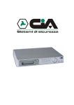
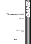
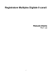
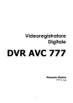
b) Connection with a single camera
DVR1A
2
GB
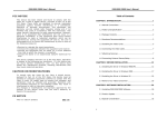
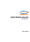
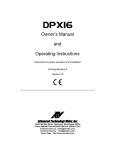
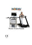
c) Connection with a multiplexer
d) Rack Mount Installation
The device can be mounted in a rack with the optional mounting equipment.
Fix the smallest side of the mounting plates (with the small holes) to the device (screw holes are provided at the
sides) and then fix the device to the rack.
e) RS232 Remote Protocol
You can use the PC keyboard to simulate the DVR keypad.
DATA: REMOTE PROTOCOL using 8-bit data – 1 start bit – 1 stop bit
FUNCTION
MENU
ENTER
SEARCH
SLOW
UP/PAUSE
DVR1A
CODE
0 x 4D
0 x 0D
0 x 48
0 x 53
0 x 55
ASCII
M
ENTER
H
S
U
FUNCTION
DOWN/STOP
LEFT/F.F.
RIGHT/F.R.
PLAY
RECORD
3
CODE
0 x 4E
0 x 4C
0 x 52
0 x 50
0 x 72
ASCII
N
L
R
P
r
GB
3. Configuration
a) Installing HDD
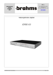
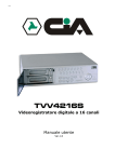
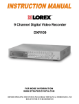
1) HDD Description
1. Handle of the HDD tray
2. Tray lock:
In position A (cf. drawing on the right), the tray is locked and cannot be removed.
In position B, the tray is unlocked and can be removed.
The key lock must be in position A before you switch on the device,
if not the hard disk drive cannot be used in a regular way.
3. Power indicator (green LED): lights up when the device is switched on.
4. HDD access indicator (yellow LED).
2) Installing the Hard Drive into the Tray
•
•
•
•
•
•
Unlock the tray lock, pull out the handle and pull the tray out of the device.
Push the release latch at the left ("OPEN") to slide the top cover backwards and remove it.
Connect the DC power cable and IDE cable to the HDD.
Insert the HDD in the tray and secure the HDD through the screw holes in the sides.
Put the top cover back on the tray and slide it forward to secure it.
Slide the tray back into the device.
3) Max. Recording Time
The recording time depends on the recording speed and quality. Please refer to the tables below:
Note: these data are the results of a test during which regular TV programs were recorded
NTSC SYSTEM
IPS
rec.
quality
Best
High
Normal
Basic
HDD type
60
12hr
15hr
24hr
40hr
30
24hr
30hr
48hr
80hr
15
48hr
60hr
96hr
160hr
8
90hr
112.5hr
180hr
300hr
120GB
4
180hr
225hr
360hr
600hr
2
360hr
450hr
720hr
1200hr
1
720hr
900hr
1440hr
2400hr
50
12hr
15hr
24hr
41hr
25
24hr
30hr
49hr
81hr
12
50hr
63hr
101hr
168hr
6
101hr
127hr
203hr
338hr
120GB
3
203hr
253hr
405hr
675hr
2
304hr
380hr
608hr
1013hr
1
608hr
760hr
1216hr
2025hr
PAL SYSTEM
IPS
rec.
quality
Best
High
Normal
Basic
HDD type
DVR1A
4
GB
b) Control Panel Description
1. HDD:
HDD is activated
2. HDD FULL: HDD is full
3. ALARM:
alarm is armed (when alarm is triggered, LED is flashing)
4. TIMER:
the device is programmed to record
5. PLAY:
recorded material is being reproduced
6. REC:
the device is recording
7. MENU:
Press MENU and enter the password (default: 0000) to access the main menu.
8. ENTER:
Press ENTER to confirm data or a selection.
9. SEARCH: Press SEARCH to search a video fragment by recording time.
10. SLOW:
Press SLOW to slow down the play speed.
11. Controls for video playback
: PLAY: to play recorded video.
: STOP: to stop playback.
: PAUSE: to pause the fragment.
: REW: for fast rewind in PLAY mode or to go back to the previous image in PAUSE. Speed
can be adjusted by pressing the REW button several times.
: FF/Right: for fast forward in PLAY mode or to move on to the next image in PAUSE. Speed
can be adjusted by pressing the REW button several times.
12. REC:
Press this button to start recording.
13. POWER:
Press this button to power on, and press again to power off.
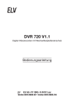
c) Back Panel Description
1. POWER: connect the provided adapter to
this connector and plug it into the mains.
2. VIDEO IN: to connect to a video source
such as a quad, a multiplexer or a camera.
3. VIDEO OUT: to connect to a monitor or the
video input of a quad or multiplexer.
4. AUDIO OUT: to connect to a monitor.
5. AUDIO IN: to connect an audio source such as a microphone.
6. External RS232/Alarm in- and output: the device can be controlled remotely by an external device or trigger
mechanism. The connections should be established as follows:
DVR1A
5
GB
25-pin COM port
9-pin COM port
PIN 1: RS232-TX: RS-232 + PIN 2: RS232-RX: RS-232: This device can be controlled remotely by an external
device or control system, such as a control keyboard, using RS-232 serial communications signals.
PIN 3: VIDEO LOSS: When video loss occurs, a signal is sent to trigger another device. During normal functioning
this signal is high ; when video loss occurs it becomes low.
PIN 4: SWITCH OUT: Connect this pin to the VCR trigger recording terminal of a multiplexer, in order to synchronise
recording signals. The default mode of this signal is low.
PIN 5: ERROR OUT: When a HDD error occurs, this pin will send a signal. During normal functioning this signal is
high ; when a HDD error occurs it becomes low.
PIN 6: REC START: This pin can accept the trigger signal from an external device to start recording. Normally, this
signal is high ; when it becomes low the DVR1A starts recording ; when it becomes high again the recording stops.
PIN 7: EXTERNAL ALARM NC + PIN 8: EXTERNAL ALARM NO: During normal functioning COM is connected
with NC and not with NO. When there is an alarm trigger, COM disconnects from NC and connects with NO.
PIN 9: GND: GROUND
PIN 10: RS485-B + PIN 11: RS485-A: The device can be controlled remotely by an external device or control
system, such as a control keyboard, using RS485 serial communications signals.
PIN 12: DISK FULL: If you've connected several DVR1A's, and the hard disk of the operating one is full, it will send
a signal to the next device, which will start recording. During normal functioning this signal is high ; when the HDD is
full, it becomes low.
PIN 13: ALARM RESET: By connecting ALARM RESET (pin 13) to GND (pin 9), you can disable the ALARM. An
external signal to ALARM RESET (pin 13) can be used to reset both ALARM OUTPUT signal and DVR1A's internal
buzzer. During normal functioning this signal is high ; when the alarm reset is triggered, it becomes low and will stop
all alarm functionalities.
PIN 14: ALARM INPUT: By connecting ALARM INPUT (pin 14) to GND (pin 9), the DVR1A will start recording and
the buzzer will be on. During normal functioning this signal is high ; when there is an incoming alarm signal, it
becomes low, the device will start recording and the buzzer will be on.
PIN 15: Com: During normal functioning COM is connected with NC and not with NO. When there is an alarm
trigger, COM disconnects from NC and connects with NO.
DVR1A
6
GB
4. System Set-up
a) Open Main Menu
Press the MENU button on the front of the device. The screen
you see on the right will be displayed. You will need to enter a
password to access the main menu. Press ◄ or ► to change
digits and ▲or ▼to change the value of the digit. Press ENTER
to confirm the password.
e.g.: password: 0000 (default: 0000)
After entering the correct password and confirming it by pressing
ENTER, this display will appear:
b) System Menu
Press the MENU button on the front of the device, enter the
password and confirm it by pressing ENTER (cf. "4a: Open Main
Menu" above)
Password: 0000
(Menu)
► Timer
Record
Alarm
Remote
System
Event
(Menu)
Timer
Record
Alarm
Remote
► System
Event
Press ▲or ▼until 'System' is selected (cf. figure on the right).
Press ENTER to enter the system set-up menu. The screen as
shown on the right will be displayed.
(System)
► Buzzer: On
HDD Overwrite: No
Date Display: Y-M-D
Date: 2002-JUL-14 (SUN)
Time: 22:38:29
New Password: xxxx
Clear HDD: No
System Reset: No
1) Internal Alarm Buzzer ON/FF Set-Up
1.
2.
3.
4.
Press ▲or ▼to choose 'Buzzer' and the ENTER button to open the buzzer menu.
Press ▲or ▼to switch the alarm buzzer ON/OFF: On = buzzer ON, off = buzzer OFF.
Press MENU to confirm the current set-up and return to the previous menu.
Press MENU again to exit and close the system set-up menu.
2) HDD Overwrite Set-Up
1. Press ▲or ▼to choose HDD Overwrite and the ENTER button to open the HDD Overwrite menu.
2. Press ▲or ▼to choose HDD Overwrite : Yes / No
Yes: HDD Overwrite on. When the HDD is full, the device will start overwriting the oldest data.
No: HDD Overwrite off. When the HDD is full, the device will stop recording.
3. Press MENU to confirm the current set-up and return to the previous menu.
4. Press MENU again to exit and close the system set-up menu.
DVR1A
7
GB
3) On-Screen Display for Date
1. Press ▲or ▼to choose 'Date display' and the ENTER button to open the 'Date display' menu.
2. Select a format with ▲or ▼: Y-M-D (year-month-day), M-D-Y (month-day-year), D-M-Y (day-month-year) or OFF
(date is not displayed).
3. Press MENU to confirm the current set-up and return to the previous menu.
4. Press MENU again to exit and close the system set-up menu.
4) System Date Set-Up
1.
2.
3.
4.
Press ▲or ▼to choose 'Date' and the ENTER button to open the system date menu.
Press ▲or ▼to change the value and ◄ or ►to move to the previous or next value.
Press MENU to confirm the current set-up and return to the previous menu.
Press MENU again to exit and close the system set-up menu.
5) System Time Set-Up
1.
2.
3.
4.
Press ▲or ▼to choose 'Time' and the ENTER button to open the system time menu.
Press ▲or ▼to change the value and ◄ or ►to move to the previous or next value.
Press MENU to confirm the current set-up and return to the previous menu.
Press MENU again to exit and close the system set-up menu.
6) Change Password (default password : 0000)
1.
2.
3.
4.
Press ▲or ▼to choose 'New password' and the ENTER button to open the password menu.
Press ▲or ▼to change the value and ◄ or ►to move to the previous or next value.
Press MENU to confirm the current set-up and return to the previous menu.
Press MENU again to exit and close the system set-up menu.
7) Clear HDD Yes / No Set-Up
1. Press ▲or ▼to choose 'Clear HDD' and the ENTER button.
2. Press ►or ◄ to choose between Yes and No:
Yes: press ►to clear the HDD.
No: press◄ NOT to clear the HDD.
3. Press MENU to confirm the current set-up and return to the previous menu.
4. Press MENU again to exit and close the system set-up menu.
All Data in HDD
Will Be Cleared
Are you sure?
(◄: No ►: Yes)
8) System Reset Set-Up
1. Press ▲or ▼to choose 'System Reset' and the ENTER button.
2. Press ▲or ▼to choose system reset set-up YES or NO.
Yes: to reset the system (load default system settings)
However, Date / Time & Password set-up will not be changed.
No: not to reset the system.
3. Press MENU to confirm the current set-up and return to the previous menu.
4. Press MENU again to exit and close the system set-up menu.
(System)
Buzzer: On
HDD Overwrite: No
Date Display: Y-M-D
Date: 2002-JUL-14 (SUN)
Time: 22:38:29
New Password: xxxx
Clear HDD: No
► System Reset: No
Note : If operation without any action until 60 seconds, it will close the set-up mode.
DVR1A
8
GB
c) Timer Programming
(Menu)
► Timer
Record
Alarm
Remote
System
Event
1) Enter "Timer" Menu
Press the MENU button on the front of the device, enter the
password and confirm it by pressing ENTER (cf. "4a: Open Main
Menu" on p. 7)
Press ▲or ▼until 'Timer' is selected (cf. figure on the right).
Press ENTER to enter the timer menu. The screen as shown on
the right will be displayed.
(Timer)
Day Start
End
Daily
00:00 00:00
Daily
00:00 00:00
Daily
00:00 00:00
Daily
00:00 00:00
Daily
00:00 00:00
Daily
00:00 00:00
Daily
00:00 00:00
Timer Enable: No
IPS
Off
Off
Off
Off
Off
Off
Off
2) Timer Recording Set-Up
1. Press ENTER to set the day selection of the first line.
2. Press ▲or ▼to select the day set-up:
Daily
: every day
SUN
: Sunday
MON
: Monday
TUE
: Tuesday
WED
: Wednesday
THU
: Thursday
FRI
: Friday
SAT
: Saturday
MO-FR : Monday to Friday
SA-SU : Saturday & Sunday
JAN-01 : special date.
3. Press ◄ or ► to select the recording start time (HH:MM).
Press ▲or ▼to set the recording start time.
4. Press ◄ or ► to select the recording end time (HH:MM).
Press ▲or ▼ to set the recording end time.
5. Press ◄ or ► to select the number the images per second (IPS).
Press ▲or ▼to set the number of IPS:
NTSC : 1, 2, 4, 8, 15, 30, 60
PAL: 1, 2, 3, 6, 12, 25, 50
OFF : not activated.
REMARK: Recording quality and format are determined in the 'Record' menu.
6. Press MENU to confirm current settings and ENTER to go to the next programming line.
7. Press ▲or ▼to select 'Timer Enable'
Yes: to activate the programmed settings.
No: to ignore the programmed settings.
8. Press MENU to confirm the current set-up and return to the previous menu.
9. Press MENU again to exit and close the Timer menu.
DVR1A
9
GB
d) Recording Mode Set-Up
1) Enter "Record" menu
Press the MENU button on the front of the device, enter the
password and confirm it by pressing ENTER (cf. "4a: Open Main
Menu" on p. 7)
(Menu)
Timer
► Record
Alarm
Remote
System
Event
Press ▲or ▼until 'Record' is selected (cf. figure on the right).
Press ENTER to enter the recording menu. A screen as shown
on the right will be displayed.
(Record)
► Record IPS: 60
Record Quality: Normal
Record Mode: Frame
2) IPS Set-Up (images per second)
1.
2.
3.
4.
Press ▲or ▼to select 'Record IPS' and press ENTER to open the IPS set-up.
Press ▲or ▼to set the IPS recording speed : 60-30-15-8-4-2-1 (NTSC) or 50-25-12-6-3-2-1 (PAL).
Press MENU to confirm the current set-up and return to the previous menu.
Press MENU again to exit and close the record menu.
3) Recording Quality Set-Up
1.
2.
3.
4.
Press ▲or ▼to select 'Record Quality' and press ENTER to open the record quality set-up.
Press ▲or ▼to set the recording quality level : best / high / normal / basic
Press MENU to confirm the current set-up and return to the previous menu.
Press MENU again to exit and close the record menu.
4) Recording Mode Set-Up
1.
2.
3.
4.
Press ▲or ▼to select 'Record Mode' and press ENTER to open the recording mode set-up.
Press ▲or ▼to set the recording mode: frame / field
Press MENU to confirm the current set-up and return to the previous menu.
Press MENU again to exit and close the record menu.
DVR1A
10
GB
e) Alarm Set-Up
1) Enter Alarm Menu
Press the MENU button on the front of the device, enter the
password and confirm it by pressing ENTER (cf. "4a: Open Main
Menu" on p. 7)
Press ▲or ▼until 'Alarm' is selected (cf. figure on the right).
Press ENTER to enter the alarm menu. A screen as shown on
the right will be displayed.
(Menu)
Timer
Record
► Alarm
Remote
System
Event
(Alarm)
► Alarm Enable: Yes
Alarm Duration: 1 MIN
Record IPS: 60
Record Quality: Normal
Record Mode: Frame
2) Alarm Enable ON/OFF Set-Up
1.
2.
3.
4.
Press ▲or ▼to select 'Alarm Enable' and press ENTER to open the alarm enable set-up.
Press ▲or ▼to set the alarm ON or OFF.
Press MENU to confirm the current set-up and return to the previous menu.
Press MENU again to exit and close the alarm menu.
3) Alarm Duration Set-Up Option
1.
2.
3.
4.
Press ▲or ▼to select 'Alarm Duration' and press ENTER to open the alarm enable set-up.
Press ▲or ▼to set the alarm duration (1 min / 3 min / 5 min / 10 min / 30 min / 1 hour / always).
Press MENU to confirm the current set-up and return to the previous menu.
Press MENU again to exit and close the alarm menu.
4) Alarm Recording Speed Set-Up (IPS)
1.
2.
3.
4.
Press ▲or ▼to select 'Record IPS' and press ENTER to open the IPS set-up.
Press ▲or ▼to set the recording speed IPS: 60 / 30 / 15 / 8 / 4 / 2 / 1 (NTSC) or 50 / 25 / 12 / 6 / 3 / 2 / 1 (PAL).
Press MENU to confirm the current set-up and return to the previous menu.
Press MENU again to exit and close the alarm menu.
5) Alarm Recording Quality Set-Up
1.
2.
3.
4.
Press ▲or ▼to select 'Record Quality' and press ENTER to open the recording quality set-up.
Press ▲or ▼to set the recording quality level: best / high / normal / basic.
Press MENU to confirm the current set-up and return to the previous menu.
Press MENU again to exit and close the alarm menu.
6) Alarm Recording Mode Set-Up
1.
2.
3.
4.
Press ▲or ▼to select 'Record Mode' and press ENTER to open the record mode set-up.
Press ▲or ▼to choose the recording mode: frame / field.
Press MENU to confirm the current set-up and return to the previous menu.
Press MENU again to exit and close the alarm menu.
DVR1A
11
GB
f) Remote Protocol Set-Up
1) Enter Remote Menu
Press the MENU button on the front of the device, enter the
password and confirm it by pressing ENTER (cf. "4a: Open Main
Menu" on p. 7)
Press ▲or ▼until 'Remote' is selected (cf. figure on the right).
Press ENTER to enter the remote menu. A screen as shown on
the right will be displayed.
2) Remote Protocol Mode Set-Up
(Menu)
Timer
Record
Alarm
► Remote
System
Event
(Remote)
► Remote Mode: RS-232
Baud Rate: 9600
ID: 000
1. Press ▲or ▼to select 'Remote Mode' and press ENTER.
2. Press ▲or ▼to select the protocol: RS-232 or RS-485.
3. Press MENU to confirm the current set-up and return to the previous menu.
4. Press MENU again to exit and close the remote menu.
3) Remote Protocol Transmitting Baud Rate Set-Up
1.
2.
3.
4.
Press ▲or ▼to select 'Baud Rate' and press ENTER.
Press ▲or ▼to set the baud rate: 115200 / 57600 / 19200 / 9600 / 480 / 3600 / 2400 / 1200
Press MENU to confirm the current set-up and return to the previous menu.
Press MENU again to exit and close the remote menu.
4) Remote Protocol ID Set-Up
You can use the RS232 remote protocol to control more than 1 DVR1A. The ID number can range from 000 to 999.
1. Press ▲or ▼to select 'ID' and press ENTER.
2. Press ▲or ▼to set numerical number and press ◄ or ► to move digit location (3 digits).
3. Press MENU to confirm the current set-up and return to the previous menu.
4. Press MENU again to exit and close the remote menu.
g) Event List
Press the MENU button on the front of the device, enter the
password and confirm it by pressing ENTER (cf. "4a: Open Main
Menu" on p. 7)
Press ▲or ▼until 'Event' is selected (cf. figure on the right).
Press ENTER to see the entire 'list of events'. A screen as
shown on the right will be displayed.
Press ◄ or ►to switch pages (8 events on 1 page) and press
▲or ▼to select the desired event. Press ENTER to play it.
(Menu)
Timer
Record
Alarm
Remote
System
► Event
PWR 2002-JAN-01 03:00:00
VLS 2002-JAN-01 01:02:04
HDD 2002-JAN-01 01:02:03
PWR 2002-JAN-01 01:02:02
VLS 2002-JAN-01 01:02:01
HDD 2002-JAN-01 01:02:00
◄: Page Up ►: Page Down
HDD: HDD error time.
VLS: video loss time.
PWR: recovery time after power shutdown (e.g. power shut down at 01:00 and power recovery at 03.00. The
display indicates that the device restarted at 03:00 after a power shutdown).
DVR1A
12
GB
5. Operation
a) Power ON
Before turning power ON make sure the HDD has been locked, and the power LED is red. After pressing the
POWER button, the POWER LED will turn to orange and all the other LEDs will turn RED, except the LED for HDD.
The screen will display "HDD Detecting" ; power on period will be approx. 5 to 15 seconds. If HDD is set as master,
the screen will display "HDD Master Connect". If HDD is set as slave, the screen will display "HDD Slave Connect".
In order to shorten the power on running time, we suggest setting the HDD as master (by means of the jumper on the
HDD itself). When the DVR1A has powered on completely, the POWER LED will turn to green.
b) Recording
Your DVR1A offers a variety of flexible recording modes. You can set it up to record continuously or programmed, or
only to record events ; you can even set the recording speed and resolution. All these options are set through the
system menu. If there should be a power cut during recording, the device will automatically resume recording when
the power returns. The original recording set-up will be respected.
There are 4 recording modes for your device: alarm recording mode, external trigger recording mode, programmed
recording mode and manual recording mode. All recording modes are described here:
1) Alarm Recording
When the DVR1A receives an alarm input, it will start to record immediately. The recording speed & quality will be as
set in the alarm recording mode set-up.
The screen will be as displayed on the right.
A = alarm trigger
= recording
OW = HDD overwrite
32GB = if the OW location shows 32GB, it means that there is
32GB recording capacity left on the HDD.
2002 - JAN - 01
01:02:03
A
OW
2) External Trigger Recording
The DVR1A can be programmed to start recording when it receives a trigger from an external device. When a 'REC
START' command is received (RS232 pin 6), the recording will start. The recording speed and quality will be as set in
the recording mode set-up.
The screen will be as displayed on the right.
E = External trigger recording
= recording
OW = HDD overwrite
32GB = if the OW location shows 32GB, it means that there is
32GB recording capacity left on the HDD.
DVR1A
13
2002 - JAN - 01
01:02:03
E
OW
GB
3) Programmed Recording
The DVR1A will follow the timer set-up to record and the
recording speed & quality will be as set in the TIMER menu.
2002 - JAN - 01
01:02:03
T
OW
2002 - JAN - 01
01:02:03
M
OW
T = Timer recording
= recording
OW = HDD overwrite
32GB = if the OW location shows 32GB, it means that there is
32GB recording capacity left on the HDD.
4) Manual Recording
M = Manual recording
= recording
OW = HDD over write
32GB = if the OW location shows 32GB, it means that there is
32GB recording capacity left on the HDD.
c) Playback
Press PLAY: the DVR1A will go into play mode and will start playing the last recording.
1) Fast Forward (F.F.) & Fast Rewind (F.R.)
• Press PLAY then press ►► for fast forward searching. Press once for double speed, press twice for quadruple
speed, 3 times for 8x, 4 times for 16x and 5x for 32x (maximum speed).
• Press PLAY then press ◄◄ for fast rewind searching. Press once for double speed, press twice for quadruple
speed, 3 times for 8x, 4 times for 16x and 5x for 32x (maximum speed).
2) Slow Forward (S.F.) & Slow Rewind (S.R.)
• Press PLAY then press SLOW for slow play. Press ►► once for half speed, press twice for quarter speed, 3
times for 1/8x, 4 times for 1/16x and 5x for 1/32x (minimum speed).
• Press PLAY then press SLOW for slow play. Press ◄◄ once for half speed, press twice for quarter speed, 3
times for 1/8x, 4 times for 1/16x and 5x for 1/32x (minimum speed).
3) Pause
Press PLAY then press PAUSE, the image will be paused.
4) Stop
Press STOP and the DVR1A will stop all actions and display the incoming signal.
5) Image by image
• Press play then press PAUSE, the image will be paused. Then press ►► to go to the next image. Keep
►►pressed for faster image progression.
• Press PLAY then press PAUSE, the image will be paused. Then press ◄◄ to go to the previous image. Keep
◄◄ pressed for faster image progression.
DVR1A
14
GB
d) Search
1) SEARCH menu / last recording
► Last Record
Full List
Alarm List
Time Search
Press the 'search' button ; a screen as shown on the right will be
displayed. Press ENTER to play the last recording.
2) Full list of recordings
Press the 'search' button and ▲or ▼to select 'Full List'. Press
ENTER to obtain the full list and a screen as shown on the right
will be displayed.
Press ◄ or ► to switch pages (8 events per page) and select
the desired recording with ▲or ▼.
Press ENTER to play the selected recording.
M = manual Recording
A = Alarm Recording
T = Timer Recording
E = External Recording
► M 2002-JAN-01 01:02:03
M 2002-JAN-01 01:02:03
A 2002-JAN-01 01:02:03
T 2002-JAN-01 01:02:03
E 2002-JAN-01 01:02:03
M 2002-JAN-01 01:02:03
E 2002-JAN-01 01:02:03
T 2002-JAN-01 01:02:03
◄: Page Up ►: Page Down
3) Recorded Video in Alarm List
Press the 'search' button and ▲or ▼to select 'Alarm List'. Press
ENTER to obtain the alarm list and a screen as shown on the
right will be displayed.
Press ◄ or ► to switch pages (8 events per page) and select
the desired recording with ▲or ▼.
Press ENTER to play the selected recording.
► A 2002-JAN-01 01:02:03
A 2002-JAN-01 01:02:03
A 2002-JAN-01 01:02:03
A 2002-JAN-01 01:02:03
A 2002-JAN-01 01:02:03
A 2002-JAN-01 01:02:03
A 2002-JAN-01 01:02:03
A 2002-JAN-01 01:02:03
4) Search a recording by time
Press the 'search' button and ▲or ▼to select 'Time Search'.
Press ENTER to obtain the search screen and a screen as
shown on the right will be displayed.
Press ◄ or ► to switch parameters and ▲or ▼to change the
parameter value.
Press ENTER to play the selected recording. If there is no
recording available for the time provided, the screen will display
"Time Not Found".
Play Time: 2002-JAN-01 18
e) Video Loss
The screen will display "Video Loss" if the DVR1A does not receive a video signal.
f) Key Lock
Press MENU and ENTER simultaneously to lock the control keys.
Press MENU and ENTER simultaneously to unlock the control keys.
DVR1A
15
GB
6. Troubleshooting
What may appear as a malfunction of the device may not be that serious at all and can be easily corrected. Check
the table below before contacting your DVR1A dealer.
PROBLEM
No power
Not working when press any button
No recorded video
Record enable does not working
No live video
REC LED is ON but the device does not record
SOLUTION
Check power source cable connections.
Confirm that there is power at the outlet.
Check if it is under key lock mode.
Press MENU and ENTER simultaneously to skip the key lock mode.
Check if the HDD has been installed properly.
Check if 'record enable' is set to "YES"
Check camera video cable and connections
Check monitor video cable and connections
Confirm that the camera is powered
Check camera lens setting
Device is in Timer mode. It will only record during assigned time.
7. Compatible Brands
a) Compatible Multiplexers
Manufacturer
AV TECH
AV TECH
AV TECH
AV TECH
ATV
CAPTURE
Dedicated Microphones
Dedicated Microphones
PELCO
SONY
ROBOT
ULTRAK
FVS
Model
AVC707N
AVC707P
AVC706N
AVC706P
DPX16
CPT_CD16
SLDX9C
SLDX16C
MX4016
VS-DX504
MX99e
KX1610CN
FVX
System
NTSC
PAL
NTSC
PAL
NTSC
PAL
NTSC
PAL
NTSC
NTSC
NTSC
NTSC
NTSC
Test Result
OK
OK
OK
OK
OK
OK
OK
OK
OK
OK
OK
OK
OK
b) Compatible HDD Brands (Appendix B)
Manufacturer
IBM
IBM
IBM
IBM
Maxtor
Maxtor
Seagate
Seagate
Western Digital
Western Digital
Model
Deskstar 120GXP (40GB)
Deskstar 60GXP IC35I060
Deskstar 120GXP (80GB)
Deskstar 120GXP (120GB)
DiamondMax 536DX (60GB) 4W060H4
DiamondMax Plus 9, Model#6Y120L
Barracuda ATA IV ST340016A
Barracuda ATA V, ST3120023A
Caviar WD400BB-00BSA0
Caviar WD400EB-00CPF0
Capacity
40GB
60GB
80GB
120GB
60GB
120GB
40GB
120GB
40GB
40GB
Rotation
7200rpm
7200rpm
7200rpm
7200rpm
5400rpm
7200rpm
7200rpm
7200rpm
7200rpm
5400rpm
Remarks
• The listed brands have been tested and are compatible with the DVR1A. Do not use other brands than these.
• In order to avoid damage to the HDD, leave the device switched off during at least 60 seconds before removing it.
DVR1A
16
GB