1
USEANDCARE
MANUAL
MANUEL
D'UTILISATiON
Model,Mod_le
DAC6003D
DAC8003D
DAC9003D
DAC6300D
DAC8503D
DACt0003D
DAC12304D
®
@-
®
_ ..'-)
Room Air Conditioner
ReadandFollowAllSafetyRules
Table of contents
.......................
1
andOperating lrlstruct[ons Before
FirstUseofThisProduct.
Danby_
Veuiliez
lifeattentlvamant
leaconslgn_s
des_curit_ellos
Inslructlonsd'utiIiaaUon
avant
I'_nsatlonTnttl_te
de
re produil.
Climatiseur de piece
Table of contents
.......................
15
DanbyProductsUmlted,Guelph,OntarioCanadaN1H6Z9
DanbyProducts
lnc,,Rndtay,
OhioUSA ,15840
11 C'2
Page
Introduction................................................................
2
Unit Speclficalions ..........................................................
2
Electrical Specifications
3
.......................................................
Energy-Saving Tips ...........................................................
4
Window _nstallation ...........................................................
4
Operating Instructions .......................................................
11
Care and Maintenance ......................................................
12
Trouble Shooting Guide .........................................................
13
Warranty ..................................................................
14
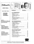
,Exler_or
Air lnIet
Air Inlet
Jr_lerior
Air Oullel
Air Fille
- Fresh Air Ventilation
Elee_rentc Conlrols
_,__.Power
Cord
Switch
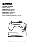
Thank you for choosing a Danby Room Air Conditioner to coot your home. This Use and Care Manual
provides information necessary for the proper care and mafntenance of ydur new Room Air Conditioner
properly maintained, your air conditioner wilt give you many years of trouble free operation. To avoid
installation diffFculttes, read these instructions completely before installing/operating your unit
NOTE: 'This unit Is NOT designed for through-the-wall
if
installation,
For easy reference, you may want to attach a copy of your sales receipt to this page,, Note tel{owing
information provided (on the manufacturer's nameplate located on the right side of the unit above the power
cord), This information wi[ibe needed when you contact a Customer Service Representative,
Model Number:
Serial Number:
Date of Purchase:
Dealer=s Name and Address:
Refer to the trouble shooting section of this Use and Care Manual if the unit is not operating correcUy.
If these suggestions do not solve Ihe problem, contact an authorized service representative or
call Danby TOLL FREE: 1-8OO-26I_)alllll:_ty"
Do not leave a room air conditioner unattended in
a space where people or animals who cannot
reac! to a failed unlt are located. A fai_ed unit can
cause extreme overheating or death in such an
enclosed, una[tended space,
Keep these instructionsfor future reference,
This symbol denotes a caution or warning
Model No.
Unit Specificatlcat!ons..............
DAC6003D
DACB003D
DACg003D
Ve!ls_e
I15W60Hz
6,000
600
to
3/3
2O0
47
'115Vt6OHz
8,ooo
810
9.8
3/3
325
49
I15V/60Hz
9,000
910
9.8
3/3
350
53
Coo!{ng
C_paclty(B[_)
,!q£ut Wattage
EnemyEfficiencyRating(EER)
FaNOoollngSpeeds
CoolingArea Coverage(Sq,fL)
NoiseLevel (dB)
UnitDimensions
W;ndow Kit Dimensions
Shipping Weight
Width
t7.75_
Depth ........... 22.5"
Height
. l&5"
Maximum Width
MJnlrnum Width
Mtr_mum Height
t7,75'
2,?-5"
13.5"
22 _
24,25"
14.75"
37'
24o5=
15o5"
37"
24.5"
1&5"
40"
28"
17,8°
97 Ib
97 Ib
!08 lb
NOTE: Specifications are subject to change w_lheut notice for further improvement.
2
Model No.
Unit Specificafications
voltage......
Inputwattage
EnergyEfllcien.cy.Ra!'in
9 lEER)
FantCooi!n
_ Speeds
Cooling]
Area Coverage{Sq.!l:.)...
Noise Level(riB)
Unl! Dtrnan_ton,_
Window Kif Oimenslons
,
DAC6360D
DAC8503D
DACI0O030
DAC12304D
115VIeOHz
6,300
640
9.8
313
2t5
47
1I 5V/e0Hz
B,50C,
860
9.8
3/3
350
55
115VI6OHz
10_000
1000
10
3/3
450
53
115V/60Hz
12,000
1220
g.8
3/3
500
56
17,7522.5"
13,5"
22"
22"
2_,25_
14,75"
24,25"
14.75"
24,25"
t4.75"
40"
4(,
_W/d th
Depth
,, He!911_.....
Maximum__j_tb
Minimum Width
Minimum He!_h!
37" ,.......
24,5':,
15.5 _
Shipping Weight
m
22:::
97 Ib
jl
IIIIIIRIII
i i ii i ,
.11 _ I,t if111,_;II!."] _ -,'_l,lt_ [lf';_!i tel _[..t
40"
17.8"
17,8"
17.S"
108 lb
108 Ib
10B Ib
,
Tab]e
1 : Suggested Individual Branch CircuI_
Nameplate Amps
5.0 to 12
AWG Wire S_ze"
14
1. All wiring must comply with local and national
electrical codes end must be installed by a
qualified electrician, if you have any questions
regarding the following instructions, contact a
quaUlied electrician,,
AWG- American Wire Gage
* Based on copperwire at 60 °C temperature rating.
2,
'Table 2: Receptacle and FuseTypes
Check available power supply and reseive any
wiring problems BEFORE installing and
operating this unit,
3. This 115V air conditioner uses 12,0 or less
nameplate amps and may be used in any
properly wired, general purpose household
receptacle. SeeTable 1 for specifications for
individual branch circuit
For your safety and protection, this unit is
grounded through the power cord plug when
plugged into a matching wall eerier. If you are
not sure whether your wall outlet ts properly
grounded, please consult a qualified
electrician.
5_ The wail outlet (3-pin) must match the plug (3pin) on the serv[ce cord supplied with {he unit.
DO NOT use piug adapters. See Table 2 for
receptacle end fuse infoTmation.If it is necessary
to use an extension cord to connect your air
conditioner, use an approved "air conditioner"
extension cord only_ (available at most local
hardware stores)
6
The rating plate on the unit contains electrical
and other technical data The rating plate
is located on the right side of Ihe unit, above the
power cord
Ra_edVeils
Amps
Wall Outlet
Fuse Size
Time DelayFuse
(or circuitbreaker)
125
15
_
15
PlugType
_
_f I_l[=t'i_.'/-\,tl#l_iliii_-'-,-.--.-,l_
Your Room Air Conditioner unit is designed lo
be highly efficient in energy savings. Follow
these recommendations for greater efficiency°
4_
1.. Select thermostat setting that sUlIS your
comtort needs and leave thermostat at that
chosen setting°
When outdoor lemperatures are cool enough,
use HIGN, MED, or LOW FAN only {depending
on your model), This clmulales indoor air,
providing some cooling comfort, and utilizes
less electricity than When operating on a
cooling setting..
2_ The air filter is very efficfenl in removing airborne
dust particles. Always keep the air filter clean.
3.
Use drapes, curtains, or shades to keep
direct sunllghl from heating room, but DO NOT
obstruct the air conditioner.. Allow air to circula|e
around the untt without obstruction.
J_YtlIi
ilIWiilf,,'i
Id I l;liCilt
IITo
injury,
disconnect
poweroftopersonal
the unit
avoid
the possibility
i beforetnslalllng orservicing,
Tools Needed for Window Installation
I
Screw Drivers:
Power Drill:
Penctl
Both Phillips and flat head
1/8 inch diameter drill bit
Measuring Tape
Scissors
Carpenters
Level
Adjustable Wrench
{ T__perat_on
read thes te nstru_ns
difficulties,
thoroughly.
YourRoom Air Cond{tioner Is designed for easy
inslallation in a single or doubEe-hung window.NOTE:
This unit is NOT designed for verlical (slider type)
windows and/or through-the-w_} appiicationslNOTE:
Save the shipping carton and packing materials for
_uture storage or transporl of the unit.. Remove from
carton, the plastic bag containing the installation
hardware kit necessary for the installation of your air
condltlone_. Please check the contents of hardware
kit agaist the corresponding model check list. prior to
Installation of the uniL
-See F!g. t
Start your air conditioner before outdoor air
becomes hot and uncomfortable., This avoids an
initi_l period of discomfort while tJnlt is cooling
off the room.
tl
j
Because the compressor Is located on the controls
side of the unit (right side), this side will be heavier
and more awkward to manipulate° Inadequate
support on control side of the unit can result in
personal injury and damage to your unit and
property. Therefore, it is recommended to have
someone assist you during the insial/ation of this
unit..
Your unit Is designed to evaporate condensation
under normal conditions. However, under
extreme humidity conditions, excess condensation
may cause basepan to overflow to the outside_
The Unit should be installed where condensation
run-off cannot drip on pedestrians or ne}ghboring
properties
A drain tube connection (exctuding hose) is provided
to redirect condensation ovedlow See Fig,.25
1, Select the Best Location
Ao This room air conditioner ts destgned lo fit easily
into a single or double hung window. However,
since window designs vary, it may be necessary
to make some modifications for sate, proper
Installation.
Bo Make sure window and frame is structurally
sound and free from dry and rotted wood,
C. For maximum efficiency, install the air condilioner
on a side of a house or building which favors
more shade than sunlight_ If the unit is tn direct
sunlight, it is advisable to provide an awning over
the unit,.
Co Providesufficient clearance around the cabinetto
a!lowfor ample atr circulationthrough the unit,
See Fig, 2, The rear of the unit should be
outdoors and not in a garage norinside a
building. Keep unit as faraway as possible from
ob_tacleslobstructionsand at least 30" above the
floororground, Curtainsand other objectswtth]n
a roomshould be prevented frombrookingthe air
flow.
E. Be certain the proper electrical outlet is within
reach of the Inslallationo Use only a single
outlet circuit rated at 15 ampso All wiring should
be in accordance with loca! and national
electrical codes.
F. DO NOT USE "REGULAR" EXTENSION CORDS
WITH THIS UNIT, If it is necessary to use an
extension cord to connect your air conditioner,
use an approved "air conditioner" extension cord
only (available at most local hardware stores)
G. DO NOT insta|l unit where leakage of combustible
gas is suspected. Your air conditioner may fail to
operate In air containing oils (including machine
oils), sulfide gas, near hot springs, etc...
Slde
obstrucllon
Ground
FIg_2
30"
Min
,,_>
1. Preparation to Remove the Air Conditioner
Slide-Out Chassis (All Models)
*
•
*
,
•
,
•
Posftion the air conditioner in the normar
(upright) position°
Remove the air filter by grasping the lJltarhandle
(on front gd]t) and s_[ding It to the rlghL Fig 2
Remove the phillips screw (behlnd filter)
seoudng the grill front to the chassis. (Fig. 4)
Remove the phillips screws located on 1he(lower
left.fright) edge of front grill (Fig.3)
To remove the front grill, grasp the lower front
corner of the grill, puiting (gen!ly) outward and
upward. (Fig.5)
Repeat this step on the 3 remain|rig comers..
Before the front grill can be completely removed
from the cabJnel, it wilt be necassary to
disconnect the (maleliemale) eleclrlcal wire
harness located directly behind the front gr_l..
{Fig 5a)
_emov_ the two phfllfps screws (lower left/right
side of cabinet) securing the slide-ouFchassb Io
the cabinet. Fig.7
Fig.1
FRONT
Ftg.2
PANEL
;
/
Fiff_4
Fig. 3
NOTE: These screws must be reinstalled
upon completion of the window installation.
(to secure slide-out-chassls)
NOTE: Some models may be inclusive of an
additional (slide-out chassis) retaining bracket and
screw located at the front of the chassis. This
bracket and screw must also be removed before
attempting to remove the sF_e-out chassis Fig_ 6
Flg_s
FIg, 5a
NOTE:This bracket and screw does not have to
be reinstalled upon compbtlon of the window
installation.
Grasp the pull handle at the front of the slide-outchassis and carefully slide the air conditioner out
of the cabinet. (Fig.6)
Please seek assistance for this procedure.
Fig. 6
.
tg_
out
._ltJw
Fig 7
2. Assembly of 1he Upper & Lower Channels,
to CabineL (All Models)
• "L" ShapedTop Channel: Install the "L" shaped
channelto the top oFthecabinetas shownin Fig,
8 using four (4) 1/4" screws.
• "U;' Shaped Bottom Channel: Installthe "U"
shapedchannelto the bottomof thecabinelas
shown th Fig. 8 usingfour (4) 1/4" screws_
NOTE. Some models may already have the
bottom channel factory Installed,
Brackets should be pe_'pendicular to the inside
window sill, wiIh step (U) bracket tight against the
sill. See Fig. 18.
C. For proper condansatlon rumolf It will be
necessary to adjust the angle/pitch of the window
brackets. This is accomplished by adjus!ing the
distance of the leveling screw on the outer wall.
The maximum angle/pitch should not exceed
more than 3116". See Fig. 18
3. Assembly of the Side Curtains to Cabinet.
(All Models)
, Slide the shutters into the topand boltom
channels as shown in Fig, 9.The shulters are
idsnlified (on frame) as left & right Attach the
shutters to the cabinetusing four 1/4" screws on
eachside.
4. Installation of Mounting Brackets
Sealing Strip (All Models)
I/4"Screw
"L" Shaped
Channel
Channels
and First
SPECIAL NOTE; Windows come in a variety of
different designs and styles_ Therefore, it may be
necessary to modify or Improvise on your
particular installation.
A. Attach the bracket assembly to the 90 ° angle
support brackets (Fig., 16) using four 1-H2" x
114" bolts. (two bolts per bracket)
Secure with the four 114" lock washers and four
1t4" nuts. DO NOT immediately tighten these
bolts as it may be necessary to adjust the depth
of the bracket assembly, depending on the
depth of your window sill SeeFig's. 18 & I9o
Tea! the bracket assembly In the window before
Installing, if satisfied, tighten all bolts. Install the
two levelling screws tnto the 90 ° support
brackets.See Fig. 16 If the levetling screwsare
distanced too far away from the wall to provide
adequate stability, it may be necessary to shim
this area with a solid piece of wood. See Fig 19,
B° Measure the length o1 the inside sill and lind the
center as shown in Fig. t"7.
ModeIs:DAC6OO3D, DACeOO3D & DAC6300D:
Measure 8.071" (205ram) on each side of center
and mark these points.
Models:DAC9003D,DAC8503D,DAC
|0003D &
DAC12304D:Measure
10.315" (262mm) on each
side of center and mark these poinlSo
Align the V-slot on the brackel with each
cbrrespending mark and mount the brackets to
the silt uping two 314"screws & two flat washers
per oracKet
"Lr' Shaped
Channel
Fig. S
Shutters
Fig,9
V-alol"_--_
o
t availing Screws _
o
_
o
=
o
o
o
Support
o
]
Btackels
Fig.16
? 0 _, o o o 0 o o o o r_'_
_':=:=
Outer Walt Coas_rucUon
FIg_18
WindowSash
5. Installation of the Cabinet
( All Models)
A, Place the air conditioner cabinet inlo the w_ndow
with the "U °shaped mounting channel (on top)
positioned in front of the upper wlndow sash. The
"U" shaped channel on the botlom of the cabinet
should be positioned in the "recessed" portion el
the track located at the front of the window
brackets. Pull the window down until it rests just
behind the Iront flange of the (top) "U' shaped
mounting channel. See Fig, 14.
Be Align one hole in the bottom of the cabinet wllh
one hole in the bracket assembly_ Secure the
cabinet !o the bracket using a 1/4" screw
provided. Repeat the same procedure on the
opposite side of the cabinet Fig. 15
C, Checkto make sure the"pitch" (angle) of the
cabinetls slanted slightly downward on the
outside, If necessary, re-adjustthe levelling
screws In the mounting bracket,Fig..18
D, Cut the flrs_tfoam sealing strip to fit the
underside (bottom) of the lower wlndow sash.
Remove the peel-off, backing on lhe foam and
attach the foam stdp to the sash. See Fig. 13.
"L"Shaped Foam Sllip
Moun_n_
Channel
Fig. 14
6. Installing the Slide-Out Chassis into Cabinet:
•
(please seek assistance for this procedure)
Carefu]|y slide the air conditioner back into
the cabinet. (in window)
Note: Ground wire must be re-installed
before completing next step,
•
Reinsta!l (slide-out-chassis) security screws
removed earlier from the (lower left/rlght) side of
the cabinet. Fig 7
•
Expand the shutter frames (fuIly) on each side
and secure the top el the shutter frame to the
window sash using one 3/4" screw & flat washer
on each side_ F'ig, 23
•
Install a shutter clamp on each side of the
(lower) shuiler frame and secure to window sill
usrng one 3/4" screw & fiat washer on each aide.
Figo23
7.
Fig 7
Shutter
r-_Clamp
Fig, 23
Reinstalling Front Grill (All Models) :
Before re-Installing the front grill back on the
cabinet, you must re-connect the (male/female)
electrical wire harness between the front gdlt
control panel and the main (cabinet) unit
(Ftg,Sa) Make sure the elecldcai connection is
t_rmiyand securely attached,
•
•
°
•
-- 2rid Foam
Seal
Position the front panel on the cabinet slarfing at
the top. The front panel lock tabs must be
inserted Into the retaining slols in the cabinet.
Repeat this procedure on all sides, making sure
the fresh air ventilation lever arm and power cord
are properly installed back to their original
position on the front griilo
Fig,, 24
r
j
=1
H
-
Secure the front grilt Io the cabinet using the
phillips screws removed earlier. Fig's, 3 & 4
Re-install the air filler.
_,
Cut the second foam seal to fit the opening
between the lop inside and outsidewindow.
See Fig_24,
-
Some installations may require additional sealing
around the _ndow and air conditioner, Check for
any air teaks and seat where necessary.
•
Under very humid conditions, water removal may
be excessive enough to ovedlow from the rear of
the unit or increase noise Ievels of the air
conditioner.If thisoccurs, you may want to attach a
section of (garden) drain hose (not included) to
the drain plug located at lhe rear of the unit, thts
wtll permit condensation to run off more
conveniently. See Fig.25
(nol intruded)
t'_'_,_
Dta}nHose
Fig, 25
7. Electronic Control Features
LED DISPLAY: The LED window displays the
following information ]ndependantiy
,
Set Cooling Temperature
Ambient Room'Temperature
•
Auto on/off Timer Programs
,, EI = (Glean Air Filter)
o
o
o
NOTE: Dudng normal operating conditions, (after all
settlngs are complete) the LED readout wiflalways
default to show (display) the "ambient room
temperalure _, In order to view the "set" temperature
of Ihe air conditioner, press either of the temperature
• key pads once.
Y
\
Control Panel
POWER SWITCH: lurns power on/off
SWING;Activates theautomatic air swing
(oscillation)leature.
(ENERGY SAVER): Press and hold the "SWING"
keypad for 3 seconds to activate the ENERGY
SAVER program, This pro'gram ts designed to
reduce energy consumption by IJmiling (restricting)
operation o| the fan motor with the operation of the
compressor. Le°
compressor off / fan off
compressor on / fanon
Watt three minutes before ad}usllng/changing
temperature settings. Adiusting temperatures too
quickly may cause the compressor overload to
trip, resulting in a blown fuse.
NOTE:When the ENERGY SAVER feature is not
selected,the ion motor operates continuously,
even afterthe compressor (cooling mode) has
cycled off. Le.
compressor on ! fan on
compressor of[ / tan on
Fresh Air Ventilation should be kept In the
"closed" position during air conditioning mode.
Fresh Air Ventilation should be kept in the "open"
position during 'lan mode" only when clearing
smoke and/or odors from the room.
MODE: Activates the FAN or COOL{NG mode_
TIMER; Activatesthe auto start or auto stop timer
programfrom 0 ~ 12 hours (1 hour increments)
ONE TOUCH: Activales a ((aclory) pro-set
tempelalure setting of 22°C (+ / - 2°C) "71.60E
FAN:Activatesfan speed settings_
(High, Medium,
Low)
A KEYPAD: Activates (increases) temperature
settings.
y KEYPAD: Activates (decreases) temperature
settings.
to
"COOLING" and "FAN" mode. The green pilot light
directly above the COOL or FAN mode wilt
illuminate, identifying the selected mode Is
operational
POWER;
Press the POWER keypad to turn the unit onlofL
'TIMER:
Pt'ass this keypad to activate the "auto start / auto
stop" timer programs. Auto start/stop programs can
be programmed from 0 ~ 12 hours Each
depression of the TIMER keypad will increases the
selected ttme in 1 hour increments.
_k TEMPERATURE SETTINGS:
Press the up keypad to increase the set (operating)
temperature of the air conditioner, Each time the
keypad is pressed the temperature is increased as
follows;
2OF (Farenhetght Scare) Maximum Setting 90OF
loC (Celsius Scale) Maximum Selling 31oc
AUTO -START:
Before activating the "auto - start" program, you must
first select (sol) the operatingconditionsof the air
conditioner.(i,,e.temperature setting and fan speed)_
Once thesettings am complete, theair conditioner
must be switched off. (non-operational)
Depress theTIMER keypad and the auto-start time
wlilappear in the LED display, select the required
time (0 -. 12hours)and the air cbnditioner willstart
automat|callyat the establishedttme,
Y TEMPERATURESETTINGS:
Press the down keypad to decrease the set
(operating)temperatureof the air conditioner.
Each
time the keypad [spressedthe temperatureis
decreasedas foflows;
2OF(FarenheightScale)MinimumSetting60OF
t °C (CelsiusScale)MinimumSetting16°C
SWING:
Press the SWING keypad to activate the automatic
air swing (oscillation) feature. The green pilot light
adjacent to the SWING keypad wilt tliuminale,
identifying"theselected mode is operattonal.'The
vertica! louvers will oscillate back and forth (side to
side) automatically sweeping cold air alternately for
comfortable cooling.To stop the air swing feature,
press the SWING keypad again, the green pilot Itght
adjacent to the keypad will go oil
AUTO -STOP:
Turn the air conditioner on and select the required
operating cond[tionso(Le. temperature setting and
fan speed). Depress the TIMER keypad end the time
w_ll appear in the LED display, select the required
auto stop time, (0 - 12hours) and the air conditioner
will stop automatically at the established time.
NOTE: It is not posslb_le to operate both the
"auto-start" and "auto-stop" feature within a
single program. All auto-timed programs are
automatically erased after the set program is
complete.
(ENERGY SAVER):
To acthlale the ENERGY SAVER feature, press and
hold the "SWING" keypad for 3 seconds,
The green pilot ]ight directly above the ENERGY
SAVER mode will illuminate, identfying the selected
mode is operational. The ENERGY SAVER program
helps to reduce energy (electricity) consumption by
controlling (limiting) operation of the fan motor with
the operation (cycles) of the compressor_Leo
compressor off/fan off
compressor on / fan on
ff the ENERGY SAVER feature is not activated, the
fan will operate continuously, even after the
compressor has cycled off. t.e.
compressor on t fan on
compressor off / fan on
NOTE: The energy saver feature operates in
"cooling" mode onty,
ONETOUCR;
Press this keypad to activate a pre-set (factory)
temperature setting of 22°C + I - 2oc (71,6°F). The
air conditioner will operate and maintain the indoor
temperature at Ibis setting.
MODE:Press this keypad to select the appropriate
operating mode. (Fan t Cool) Each depression of
the MODE keypad wtli alternate between the
11
wash _nlukewarm water. (below 40°C 1104°F):
For very dirty conditions, wash with soapy water
or a neutral cleaning agent
FAN:
Press thlskeypad to activate the appropriate fan
speed setting. Each depression of the keypad wi!l
aItemata through High, Medium, Low fan speed
options. The green pilot tight directly above the FAN
speed option will illuminate, identifying the tan
speed selected..
AIR FILTER INFORMATION
The air filter prays an important role effecting overall
perlormance levels of any air conditioner.A clean air
filter will maximize cooling efficiency. A dirty air filler
will mihimize cooling efficiency. It Is important to
keep the air filler =clean" at all times.This unit is
inclusive of a program that will display a message
prompt "Et" (= CLEAN AIR FILTER) tn the LED
display indicating when it is time to clean the air
filter.
E1 = CLEAN AIR FILTER:
A message prompt"El" will automatically appear in
the LED window Indicating, when II is time to clean
the air filter. The E1 program is a (built-in) time
device that operates based on tota! (air conditioner)
running time. It is very important to keep the air filter
clean at all times in order to maximize cooling
efficiency. (See Cleaning Air Filler)The air filter
"must" be cleaned when 1he"El" message ls
displayed.To cancat (eliminate) the El message
from the LED display, the air conditioner "must" be
disconnected (unplugged) from the power supply
and re-connected. This action au!omatically re-sets
the "El" program internal time device.
NOTE: In the event of a power failure, the "El"
program is automatically re.set, therefore we
suggest you remove and clean the filter before restarting the unit.
AIR FILTER REMOVAL:
The atr filter ts located behind the air intake front
grill. To remove the air I_ter, grasp the filter handle
located on the front of the grill and sIide - it (out) to
the righL.
To reinstall the atr filler, reverse
the above procedures.
CLEANING
I. Use a vacuum cleaner wtlh soft brush attachment
to remove heavy soil.
2. Wash the filter in lukewarm water.. (below 40°C
104°F): II the filter is very dirty filler, wash with
soapy water or a neutral cleaning agent. (NEVER
WASH AIR FILTER IN DISHWASHER)
TEMPERATURE DISPLAY CELSIUS I
FARENHEIGHT:
It IS poss_le to change the LEO temperature display
to read "Celsius" or 'Farenheight", by pressing the
(temperature) _ keypads simultaneously, The green
pilot light undeithe "ocpP' (temperature symbol) will
Illuminate, identifying lhe mode selection.
Do not use harsh cleaning chemicals to clean the
filter as they may damage the plastic and filler
mesh°
3. Rinsethe filterwith clean waterand
dry thoroughly before re-installing.
When servicing the air conditioner,be sure to
turn the air conditionerto the "OFF" position
and disconnect the power cord from the
electrical outlet°
NEVER operate the alr conditioner without the
air filter, as dust/dirt particles can contr_ute to
equipment failure.
1. DO NOT use gasoline, benzine, thinner or other
chemicafs on the air conditioner, as these
substances may, cause damage to the paint finish
and deformation of plastic parts.
2. Never attempt to pour water directly on unit as
this wllI cause deterioration of the electrical
Insulation.
3. When the air Inlet grill and cabinet are dirty,
AIR FILTER
End-of-Season Care
1. Operate the fan only (high speed) for half a day
to dry out the internal components of the uniL
2. Turn off power and remove plug from walt sockeL
3. Clean air filterand exterior cabinet.
4. Store air conditioner (covered) in a dry location
12
Frequently,
aproblem
isminor
and a service
callmay not be necessary, use lhls troubleshootingguide for a
possiblesolution, II the unit continues to operate improperly, call Danby'sTo|! Free Number t-800-263-2629 for
assistance, or carlone of our service depots listed tn the enclosed ".AuthorizedService Depot"listing provided
with this uniL
Difficulty
Possible
Cause
Air conditioner will
not operate.
No power touniL
Suggested
Solution
Check connection of power cord to
power source.,
Check fuse or circuit breaker
Check the appropriate setting is selected
inefficient or no cooling°
No]sy unit.
...........................
i,,
Dirty air filter.
Clean or replace air filter,
Unit size inappropriate
for application,
Check with dealer to determine proper untt
capacity for application.
Blocked alr flow
Remove obstruction from grill or
outdoor louvers.
Power Interruption, settings
changed too quickly, or
compressor overload tdpped.
Turn the unit off and wait 5 minutes before
attempting to restart
Loose parts
Tighten loose parts°
Inadequate supporL
Provide additional support to unit,
,
,,,,, ....
Odors.
Formation of mold, mildew, or
algae on wet surfaces.
Clean unit thoroughly.
Place algaectae tablet in base pan,.
Water dripping outside.
Condensation run.off is normal
during hot and humid weather_
Add flexible tubing to redirect water flow,
see Fig,25
Water dripping inside.
Unit Is not properly angled to
allow water to drain outstdeo
Unit must be installed on an angle for proper
condensation run-off,. Check the unit and
make any adjustments.
Ice or frost build-up,
Low outside temperature.
When outdoor temperature is approximately
65°F or below, frost may form when unit is in
eooltng mode. Switch unit to FAN (only)
operation until frost melts.
Unlt alr filler is dlrty_
Remove and ciean filter
NOTES;
1. ff circuit breaker is lripped repealed/y, or fuse is blown more than once, contact a
qualified technician.
2
When unit is installed using proper installation steps, uni_is properly tipped towards the outdoors
to allow for condensation run-off-
13
LIMITED
AIR CONDITIONER
WARRANTY
TH_qua1_y
p_oductis
w_rranted
Iobeflee
fmrn
m_afa:iure=%
deJecls
in_lerlal
and
wo_man_hip,
providad
the(
the
unit
isesec=
un#er
the
norm_
opemlJng
condilioas
intaxk4l_yBema_[astut_r_
This
w_m_yIsavariceo_1_
tatheperson
tov_m theu_twas
origtna_y
sold
byDerby
orbyan_[ho_lz_dis?n"outo.r
elDanby,
andtsnon-.tr'_sle_ble
TER_|_
OFWARRANPI
8e_nd7h_g,_
FifthYea;
Ser_
Du_ng
lhoti_alyeez
{1).any'declr;ca!
padsdlhispt'_ lourdtaIJedelo@ve,
_luCaganys_ledsy_lem
_nils._Atbere;o_i_e_l
ot
_e_eced',
_1¥_ar_!afs
¢p[o_o
a[noch_g_
totheOFIIGINAL
pu_ero
Du_ing
_ nextfour
yo_s(4)
anyputofthesealed
system
_o_,dtobe
def?_ve
(cor6_t'%9
d compress,
c_enasr,evew_lor,
d_r and_ e_tsdl_b_ '_Uber_placed
'_,,:_out
cha|ge"fl_epurchasershag_yfora]tlabo_a_dalumtre_hl_ullngthist_._ryea_
(4)pe_dlorrep_or_aplac_ent
ol_se_ed system
_mponenL_
,_ ua_5el__agr_aad
asnenof_r.ctt_na!
dga_osealed
system
la_uza
end_\'_anl_g
an_g_
d=inglhe
exisling
fo_(4)yo_ wiltbesubjec[to
an@p_oplia_e
dap[c_f_tim
oruse.zlee,
_I_i_g
_nyande_l_10hl
_rges t_o_g
l_,e_tag_nst
theco_,_m_z
_tac_yanz_al_om\vl_ your
_ waspuchesed,
ormntectyou,
nearest
au_hor;zoci
D_ serv)ce
_epot,_he_a
aerate
mus[
bep_dormad
by_q_ed smv_ce
tech_c_n._sauceisper_armed
ont_eunils
byanyone
o[her_m _ _ulher_dser_ce
depot,
e__he
u_tisusedlotc,_mete_
_p_tto_, e_obi[pali_ns
oiD;_'_y
ruder_s \varzan_y
_ _eelanend.
EXCLUSIONS
Save
_ he_nprov_ed,
Oe_9'P_o_lu_
LL,_'_(Cer_a)o_D_byFzod_s1_¢_
[U.SA,),t_a'earenoo_ervr_nttas,
oo_i)ions,
;ep_es_talions
o_
g_as_ees,
express
orimpF_m_de
orintended
byD_y PreludeUm_ed
oritsauthorized
dis_i_ and_ o_e_vr_rran_e%
cudilion%
_rep_.s_ens
m
guarantees,
_duding
_yw_nties,co_ii_ens,
representalions
_ 9_an_ees
_derany,_laol8e_sActo_-_elegislatim
orsta_eishazyexpresS]
ex_uded.
Sa_,.e
ashere_
p_ov_ed,
Derby
Pro_'cts
Umltc--d
(O_._a)ozIDa_yPr_u:_s{no(U£A),s_l notbereOo_b.%
lot-any
dodgestop_so.ns
o_
prope_',
_
theenitffself,_._,'so
o','az
caused
= any_ns_Jenliat
damages
a_sin
9from
t_ mallun_on
oftheLmi!
a_ bythepurch_e
o1theuntt,
the
p_chasez
da_hereby
agree
to_rnr_ ends_vs
ha_mtss
D'_yPre_f_..L_
L_i_ed
lmmanyc_mfordarra_.s
topecansorprope_caused
bytheu_i_.
GENERAL
PROVI_IOH_
._o_rr_ orJoeL,
ante;_ezeb
co_[_ne_
ozseisatshellapply
wl_md_ageorrepair
isc_used
byar_ofthefallowing:
1) Pa_var
Feaze.
2} I_rn_.[te[n_ansllorwhenmov;_eep_li_ce_
3) lmpropez
parersWp_such
nslowvoi_e,_elect_h_usa
w_ or_ad_ate_
4) _c_._e_e_n_abase_rrd_e_theeppT_ce_ch_aderI_e_kc_ce_a_`_nin_m_rn_r_errna]_pe_a_in9c_dit_s_
{eXtremely
_gheri_,,'
_amtemperature)
5'1UseIolcommard_
orit_dustri_l
purposes
G) Fil_fe_dam_ge,
lheff,'_;'_r,=_l,l_osfi_ty,
actanfGodsu_hu_._nes,
lioodse_e.
7} S_ ca_s
read'_gt_custame_
educais_
P_lofpu_aseda_ev,
i_bemqui_dlo|v,mra_.yda'_;s%pie_sern_l_b_tsofs_e
Intheeve_wer_anty.r.er_cei_r,e_ui:e_,p_esenttl'_.sdocu_e_[onur
AU_ORIZ_S£RVIC£
0EPOTo
Wurenty
SaUce
A_z
Can_llonsrs
t_igt.Jn
CanadaWllh_ln
United
States
Home
InHome
t_an_P,_odacts
13mlte_
FI) E_ tTl_ GOTO
W;'_elawI_,Gualph_
O_Io_ Canzz_ia
BIHGZ_
Telephone:
[_l_}B37-0_;n
FAX:{__)B3?.e44_
Oa_' Pzo_u:_lot:,
O|,_1
Teiepheee:(4'_9)425.B_27
FAX:(t19)423,_29
Page
tnlroduction
................................................................
16
Fiche signal6tique ...........................................................
16
Sp6cificalions 61ectriques ......................................................
t7
Conseils d'6conomie d'6nergle ................................................
I8
Installation dans ta fenOtre ....................................................
18
Instructions de fonclionnement .................................................
25
Pr6caulions el enlretlen
.....................................................
26
Guide de d6pannage ...........................................................
27
Garantie ......................................................................
28
Panneau!
•Enlr6a d'alr
exl6deure
.8o_e d'alr
_nt_rieure
Commutaleur de venlilalion d'alrfr_Js
Commandes 6teclronlques
.Cordond'altmenlatlon
15
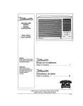
Nous vous remerclone d'avo}r chols! un climaliseurde chambre Danby pour refroidir votre Iogement Ce manuel
d'utitisatton el d'entretten foumit ]es renseignements n_ceesa[respour prendre soin et enfretenir volra nouveau
climatiseurde pleeeo S'lt est ad_quatement entretenu, votre ctlmaliseur vous donnera de nombreusee armies
d'utilisatfon sans probJ_mg. Pour _vilor toute difficull6 d'inetalfation,veuillez lira lee prgsenles instructions,
compl_.tement,event d'tnetaller et de faire lone!tannervotre appareil.
REMARQUF.: Cet apparell n'a PAS _t_ con_=upour une installation _._ravers une paroi.
A titre de r_f6rence, vous pouvez agrafar _.celia page une copie d8 votra re_u d'aohat de l'appareiL lnserivez tes
mnseignements sulvanls fournfs(cur la plaque signai_tique du fabrican! ligufant sur le c6t_ droit de l'appareil audessus du cordon d'atimentation). Vous aurez besoin de ces rensetgnemenls si vous contactez un repr_sentantdu
Service b la clien',_le
_um6ro de mo_.le:
Num_m de s_rie:
Date de I'achat
Nora et adreseedu concessionnaire:
Veutllez vous reporter _ la section du d(_pannage flguranl dens ce manuel d'utilisalion el d'entretian, si I'appareil ne
fonctionnepas correctement_ Si eerie suggestion ne r6sout paste probt_me,contactez un repr_senlanl auloris_ des
services ou appelez directemen! Danby, sans frais, au num(_ro ',1-800-26I_ll_Ntlby
Vauiltez conserver ces Inslructlons pour de futures
rf_f_reaces.Ce symbole Indique une RiSe en garde
ou un avertissemant
Ne laissezpas ur_ciimatlseur
de placesanssurveillance
densunespaceo_ se t_ouvenldes gensoudes anlmaux
qui ne pauventpes r_aglr _ un apparetld_fafllanL
Un apparelld_faIliantpe_t causerunesurchaufleextr6me
ou ent_aTner
Ia morl daneun lel espaceconllr_8el
sanssurveillance.
_,]edibleNo,
DACB003D
FichesLqnal_ttque
Voltage
115VI6DHz
Capaci_t6
de mtroidtssemeot,,(B!u/h},
6,000
Puissanced'enlr6e
600
R{_:jirnB
nominald_efficacll_
_ne_l!gue (EER)
10
Vitessesve_tiIateurtra_roldisssment
3!3
ID}mens]ons
de Fakede refmldissement
(p)eds2)...................
2,00
_liveaudu bruitS,
47
Dimer_sions de t'appareIf
...............
_
_rgBur
Profondeur
Ha_leur
Dimens'_ns
ensemble
fen6b'eLar,qeurmaximum
Lan_eu_
minimum
Hauteurminimum
Poldsd'expddltlon
DACBO03D
DACe003D
t15Vt60Hz
115VIBOHz
9,000 --_
B'IO
9,8
_,qoo
BIO
325
49
350
53
!7,75 po _
22,5 po ......
t 7 75 po
22,5 po
22 _o.,
2.4,25 po
13,5 pe
13 5,po
14,75,,,po
37 po
24,5 po
,j,5.,5 po
97 Ib
37 po ....
.24_5po
15,5 po
97 Ib
40 !_O
_ 2Bp_
17_8po
108Ib
Remarque: Lee specifications peuvent 6Ire chang6es sans avis, _ litra d'am_iioration.
16
........... =.......
Model No.
Unit Spectflcaficatlons
DAC6300D
DAC8503D
Vo!ta_e
115Vt60Hz
115Vi60Hz
6,300
640
9.8
313
215
47
CoolingCapacity (Btu/h)
!nput Wattag.e......
EnergyEfficiencyRating {EER)
FenlCoolln_Speeds
Coo!!ngArea Coverag_
NoiseLevel{de)
WlndowKtt Dimens!ons
Polds d'exp_dllion
115V/60Hz
........
8.500
860
9.8
.
3t3
350
55
Width
Depth
HeLght
t7,75po
22,5pe
13,5po
22p0
2'4.2_po
14.75po
Maxtmum_
Minimum Width
Minimum Heighl
37po
24.5p_
15,5po
40pc
97 Ib
108 lb
DACI2304D
115VI60Hz
t0.000
1000
t0
3t3
450
53
12,OO0
1220
9.8
3t3
500
56
22po
24,25po
14.75po
22o_
24.25P0
14.75po
....
.......................
40pc
28po
17,8po
40pc
28po
17,8p0
_
108 Ib
108 Ib
La prise murals (_ 3 brochss) dotl correspondre&
]a fiche _.3 broches sur le cordon de service fourni
Toes les c&btagssdoivent _tre conformes aux
codes _lectrfques Ipcaux et nafionaux et doivent
_tre install_s par un _leclriclen qualifi_,. St vous
avez la molndre queslion au sujet des Instructions
ci-dessous, conlactez un _lectricIen qualili_.
avec rappareiL N'ulilisez PAS de fiches
d'adaplatien. Vofr le Tableau 2 pourlss
renseignementa sur los prises de courante! los
fuslbles S'I! est n,_cessaire d'utJliseruna mllonge
_lectrique pour brancher volts ctima_tseur,utilisez
une rallonge _lestrique approuvde pour ctimafiseur, exctusivement, (disponible darts ]a
plupart des quincagleries)o
V,_rifiezla fourn_tured'alimsnlalion_lectriqua
disponibleet r_sclveztoulprobl_mede c&blage
AVANTd'lnstalisret de faire fonc_lonnercat
appareiL
3_
DACI0003D
La plaqueslgna!_fiquesur f'apparetl
sentientdes
donn_es_lectriquesel techniques;ells se trouve
sur le cSt_droit de I'eppareil,eu-dessusdu cordon
8'alimentation
Ce climaliseur & 115 V utttise 12 amperes ou mains
de puissance nominals et pout OIreutilts_avec
touts prise de courant domestique de but g_n_ral,
ad_quatement c&bl_e. VotrieTabteau 1 pourles
sp_cfficattons pour circuit de d_rivation individual
Tableau2 :Types de prises de courant el de fusfbles
Pour votres6cuiit_ et votre protection, cot appareil
est mis & la masse par la fiche du cordon
d'al[mentationIorsqu'etle est branch_e dens une
prise mumla correspondante. Si vous n'Otes pas
certain qua votre prise de ceurant mum]e est raise
& la masse ad_quatement, veuitiez consulter un
_leclricten quatifl_.
Voflsgenominal
Amps
Prisedecouranlmorale
..D_DIDlmens!onS
_Ju!US!b!_.............
Fuslbto_ retardement
Tableau 1 : Circuit de d_dvatton _,ndtvidue! sugg_r_
Ful_encen_mlnele: amperes CalibreAWG"
5,O & 12
14
AWGAmericanWireGage
* B_ ourunfilde cuivre&unevalaurlimitsdetemperature
de 6_'C°
I (eudtsjoncteur)
17
125
15
_'ll_
15
Type deliche
Votreeltmatlseurde p|_oeest congupour_tre
d'unegrandseffieac_tdclans |'dconomled'_.nergle.
PourI'augmenter
encore,vaulllezsutureIes
recommendations
ci-dessous:
Commencez& fairefoncttonnervotreclimattseur
avantque I'a_rext_rieurne soitchaudst
inconfortabie.
Cola6viteraune p_rtoded'inconfort
torsquel'apparetlcommence_ refroldirta pi_ceo
1. S_lectionnezun r_glageduthermostatqui
cony]anne
auxbeso[nsdevoltaconfortet laissez
le thermostat
au r_glagecholsi.
Quand les temperatures ext_deures sent assez
lrai'ches, utillsez seufemant Ie ventilateur _ Ia
vttesse ELEV_E, MOYENNE OU FAIBLE (seton
votre module). Cela fair clrculerrair int_rieur el:
produit un cerlain refroidissement conferrable et
uttlisa moins d'61ectdcit_ clue lorsqu'on felt
lonctionner le climattseuren mode refroidissement.
2.
Le fl]tre & air est tr_e efflcace pour _]iminer ]es
part]culesen suspension dens I'aJr,.Gardez
toujours le fiiire propre.
3. Utll{sezdesdraperies,rideauxou storespour
emp6cherlos rayonsdirectsdu soleitde r_chauffer
la piece,mais n'obstruezPASIs climatiseur.
Permeltez& I'a[rde circularaulour de I'apparei},
sansobstacle°
m
ll__-';llf;_ll I;'1 i {a}_] lJT;1_ 1.1 I1_1:11;I: _I =il1:1 _ll
'
IIIIIIIIIIIIIIIIIIIIIII III
carton,tesacen plasttquequi ceniientlalroussede
quince_lerie
n_cessatre
pourI'lnstellatlen
devotre
cllmattseuro
Veuillezv_rttterlecontenu
de la l:reussede
qu_,ncaJllerie
d'tnstallation
enlecomparant
_ la listsde
v_rilication
dumod_lecorrespondanI,
etce,avanl:
l'tnstaliationde I'appareiL
Voirfig. I
I
corporelle,
de
Pour _viter dla_branchez
possibllit8l'aUmental:ion
d'une blessure
J'apparei]avant sor_instailationou son
enli'etien_
_i_
Oullls n_cesaelres
pour_nstallattondens unefen_tre
Toumev[s
A t6tePhitlpset plate
Percsuse_tectrtque M6chede 1/8pode d{am
Crayon
Ruben_ mesure
Ciseaux
Cl_r_glable
Niveau&bulle
Pour_v_terlosdlfllcull:#.s
d'lnstallatZon
et de
fon=_onnement,veulllezIlre leaI_structtons
attentivement°
Votre climallseur de chambrea 616con_upour une
Installationfacile dens une fen6tre & ch_issis&guillotine
simple ou double.
REMAROgE: Cet appareiln'a pas 6t6 con_ pour des
fen_tres vertlcales (de typecoulissant)ou pout 6tre
Instants
& lraversune peroL REMARQUE:Conservezta
cartond'exp_ditionet le mat_riet d'embaltagepourfutur
entreposage ou transport de I'appareiL Otez I'appareildu
18
Votre appare]l a _t_.con;u pour que la condensation
s'_vapore dane des conditions normales.. Cependant,
en pr6sence d'une humiditY, extreme, un surplus de
condensation pout provoquer un d_bordement de la
cuvette de base versI'ext_rieur. Uappareit dolt _tre
installS,de telle sorts qua r_coulement de la
condensation ne se d_verse pas sur des passants ou
sur des prepri(_l_s avoislnanles.
Comma Jacompresseurse trouve du c51_des
commandos de I'unil_ (c0t_ dmil), cs oSl_ est plus
Iourd et plus difficIle fl manipuler. Un sou_ien
Inappropri_ du cOt_ des commandesde t'apparell
_eut causer des btessures at andommager l'apparetf
at d'autres biens mobtliers. C'est pourquo] II est
recommand_ que que/qu'un vous aide au cours de
t'lnsta!iation de cat appareiL
Une connexionde luyau de drainage (,_l'exclusion du
tuyau) est fournie pour r_echeminer le d_berdement de
la condensatlon_Volt fig. 25.
Cho_x du melileur endroit
N'UTILtSEZ PAS DE RALLONGES
ELECTRIQUES ,, ORDINAIRES - POUR CET
APPAREIL S'il esl n_cessatre d'utiliser une
raltongepour brancher volta climattseur, utilisez
unlquement une rallonge approuv_e pour ,,
clJmatiseur ,, (d|sponible clansla plupart dee
quincatileries locales)
A. Ce climatiseurpour chambre a _t_ con_u pour _tre
install_lacltement dens unelen_Ire & ch&ssis_.
guillotine simpleeu doubts. Cependant, comme le
design de ia fen,_tre pout verier, it peut _tre
n_cessalre d'y fatre quelques modifications pour
une Installations6cudlaire et appropri_e.
G_
B, Assurez-vous qus la fen_tre st son chassissent
structurellement sol[des et exempts de bois sac el
pourrio
C. Pourun maximumd'effcaeIt6,Installezle
clirnaliseur
sur le c5t6de Ia malsonou de
l'irnmeublequi se trouve plusseuvent_ I'ombre
qu'au soleil. Si I'appareilestdirectementsous tes
rayonsdu so_eil,itestrecammandabled'instaHerun
auventpour prot_gerI'unit_.
D. Laissez suffisamment d'espace llbre autour du
caisson pour permettre une ample circulationd'air
_.traversl'appareiL Voir fig°2. Uardbre de
I'appareti dolt donner sur l'extSrieur de la maison et
non pas dens un garage ou fl rint_riaur d'un
immeubTe..Tenez t'apparei! aussi loin qua possible
de tout obstacle ou obstruction el au mains b 30 pc
au-dessusdu planeher ou du sol. 11ne faut pas
qua lee ddcaux ou d'autres obJets & i'int_rfeur de la
p_ce pulssent bloquer le flux d'air
E, Assurez-vous que la prise _lectrique approprt_e se
trouve _.la port_e de I'Installation. N'utilisez qL,'Un
circuit,_ prise uniquecalcul_ _, 15 ampL=res.Tout le
c&blagedoit _tre con|orme aux codes _lectrlques
Iocaux et nationaux.
t9
N'inslallez PAS rappareil & un endroit ell on
smtp_;onna une fulls de gaz combustibles.Votre
climaliseur l_euttomber en panne dens une
atmosph_.re_quiconttentdes huiles (y compris des
hui]es pour machines}, des gaz sulfur,s, ou s'l[ eel
pros de sources d'eau chaude, etc."
1. Preparationpourenlevezle chassiscoultssant
du climatiseur (Touslab rnod_les)
Mettezt'apparei]
b rapositionnormale(verllcale).
Enlevezle fitlre _ airen salslssant
la poign6edu
fittre(grillefronlale)et en la gltssantversla droite,,
(F g,2)
Enleveztavts_.t_le Phittps(derzl_rele flltre)qul
f_xela gdllefrontaleau ch&ssis,(Fig_4)
EnlevezteevL_& t_tePhilipsse trouvantsur l'ar_le
dela gMItefrontale(_ gaucheet _.dmlte anbas).
Fig,1
F|g,2
(F go
3)
Pourenleverla grillefrontale,salsissezlecoln
inf_deurfrontal de la grille,ttrez(gentlment)verb
' l'ext_rleuret Itnt6rleur.(Fig.5)
R_p_tezcet_e_tapepourlee 3 coins restantso
Avan!qua la gdlle frontalesolt compl_tement
en!ev_edu caisson,iisara n_cessalrede
d_brancherle harnalsdes fifs _lectriques(m_te et
femelle)sltu_direclemenlderrierela gri+Fe
lronlale.
VIS DU PANNEAU
AVANT
Fig, 3
(Fig.Sa)
Fig, 4
Enlevezles deuxvls Phitips(cSt_sgauchetdroltdu
caisson)
qui fixenlle ch&sstscoulissantau caisseno
REMARQUE : Ces vie doiven! _tre r_lnstall@es_.ta
fin de i'}nstatlatienclansta fan,Ire (afin de fixer le
chassiscoulissant).
REMARQUE : Cerlalns mod_les peuvent 6tre
n_cessiter une bride de fixation et vts
suppl6menta_res (chassis coulissant)_ I_avantdu
ch,%sls. Carte bride et carte vis doivent aussi _lre
enlev_es avant d'essayer _ enlever le chassis
ceullssante×|_rieur, (FIg_6)
F_g. 5
REMARQUE:Cette
bride et cartev]sne doivent
pas6tre r_instatl_es
_ ]a fin de I_n_tallationdane la
fan,ire.
Sa]sissezla peign_equi se trouve & I'avantdu
chassiscoulissant,
et g/issezaveosoInte
cllmatiseuren dehorsduca[ssono
(Fig..6)
Veuillezvous faire aiderpourcarteprocedure.
- CH_SStS
COULISSANT
Vie DU
1=19.7
20
2.
1
Montage des canaux sup6rieur et tnf6rleur
sur le caisson (Tous lee modb]es)
Canal sup6deur en forms de. L _ : Installez le
canal en forms de ,, L ,, au_dessus du caisson tel
que montr6 b ta Fig. 8, en utlllsant quat_e (4) vis de
1/4 poe
Canal lnf6rieur en forme de - U ,, : lnstallez le canal
en forme de. U ,, au bas du caissontel que montr_
& la Fig. 8, en utiHsant quatre (4) vfa de 114po.
REMARQUE : Cerlalns mod_les peuvent d6j_,avo_r
]e canal inf6deurinstall6,_ I'usine.
avec chaque marque correapondanle el monlez los
supports sur le reborden utUisantdeux vls de 314
poet2 rondelles plates par supporLLee supports
deivent 6Ire perpendicufairesau rebord tnl6rieur de
Is fen6tm, ayes Ie support en (U} serr_,centre le
cadre. Volt Fig.,18.
C_
Montage des rideaux lat6raux au caisson
(Tous lee mod_les)
FaitesgItsserlesvolelsdanaloscanauxsup6rieur
et inf6risur,commemontr6 _ ta Fig°9. Cesvoleta
son! identifi_.a(surle cadrE)en rantque volets
gauchoset droits_Fixezles volels au caissonen
utllisantquatrevis de =po aur chaquec6t&
4, Installation des supports de montage et de
la premt_re llsl_re _.calfeutrer
(Tous los mod_les)
REMARQUESPFIC1ALE:Losfen6treapr6senlent
toutsunavarietalde stylesdiff6rents.C'est
pourquottl peut6tre n6eeasairede modifierou
d'irnproviservotreinst_lationparttculi_re.
A. Fixez i'ensembte
support auxsupportsangutaires
de 90_'(Fig.16)en utiliaantles boulonade 1,5 po x
t/4 pc (deuxparsupport:).
Rxez aveclos quatrerondel]es
de s6cudt6de _po
et tes quatre_crousde, pa Neserrez PAS& fond
tmm_diatementcos vis,carUpourrait6tre
n6cessalred'ajusterla profondeur
de l'ensemble
supporten foncl_onde la profondeurdu cadre de
voltsfen6tre.VoirFigures18 & 19. V6rifiezet
testezt'ensemble
supperldens ]afen_tre avant
I'installation Si vous _tes satlsfalt,aerrezrouteslee
vIs, instalfezleadeux vie nfveleusesdans lea
supports angulaireade 90°(_querre).Voir Fig, l&
8i los vieniveleusessent trcp diatantesde ]a parot
pourfoumtr unestabilit6ad6quate,tlpout6trs
n6oessatrede diminuercgttedistanceaumoyen
d'unesolidspt_eede bob. Voir Fig 19.
Pourun_coulementappropd6de la condensation,
il sere n6cessaire
d'ajuster t'anglede calagedes
supportsde lalen6tre,Colaee fairen ajustantla
distancede la vie nlveleusesur la paroiext_deure.
Uanglede calags maximumne doltpas d6passer
3/16po,Fig. 18o
de ,, U.
(espaceplusp_tJtz_
I'avant)
Fig. S
Cadre
desvolets
Volels
Fe_l_ en
c_
"'L==_
O 0 0
o
o
o'o
_o
2
o.?..o
}
Enaembb
supporl_
Besiege,
demontage
I t ///
"_" Suppert
angulalm
9O:
Viet]tve_euses _
B. Mesurez la longueur de l'inl6rieur du rebord de la
fen6lre et trouvez le centre, tel qu'il est montr6 _zla
Fig 17.
Mod_]es DAC6003D,DAC8003D
& DAC6300D:
MesurazS.,071 po (205mm)_ partirdechaque
c5t6 du centre et marquez ces points.
Modbles DAC9003D,DAC8503D,
DACtO003D
& DAC12304D:Mesurez
I0.315 po (262turn) _,
partir de cheque c6t6 du centre at marquez cos
points. Alignez la fonts en V sur le support
2"1
Fig. 16
Rg, 17
Va _2 °"
Constmclion
pate]ex_deufa
Fig° 18
WindowSash
oooo0oooo
Canardo
Bande
_o_laOa 811
moLl.See
forme
de =L,,,
5, Installation du caisson
(Tous les modules)
Rg. 14
A, Placez le caisson du climatlseurdens Jafen6tre
avec le canal de montage en forme de ,, L ,, (en
haul) postlionn_ & ]'event du cadre sup_rieur de la
ten,Ire. Le canal en forrnede ,, U. au bas du
caisson dolt _lre posll}onn_clans Is ralratt de la voie
qui se trouveb ['avant des supports de la fenStre.
Ttrez la fen6tre vers le bee jusqu'&ce qu'e]le repose
Justederr[bre le rebordfrontal du canal de montage
en forme de ,, L ,, (sup_rieur) Voir Fig. 14.
B. Al{gnez un trou au has du caisson avec un trou de
t'ensemb]e support, Fixez Is caisson au support
avec une vis de z po, foumie. R_p_tez sur te c6t_
oppos_ du caisson. Fig, t5,
C. V0tifiezpourvousassurerque l'tncltnaison(angle}
du caissonest I_g_rementdirlg_e vats le bas
i'ext6fleur. Si n6cessake,r_ajuslezles vis
ntvaleusesdensla bride de montage,VoIrFig. 18.
D_ Coupez Is premiere list_re & calfeulrer en mousse
pour qu'elle se fixe ad_quaternent eu-desseus du
has du ch&ssis de ia fen_lre, Enlevez le dos
d6ta_able de la mousse el fixez-le au cad_a. Voir
Fig, 13o
22
6. Installation
caisson
du chassis coulissant clans le
{veulllez demanderde |'aide pourcette _tape)
Failes glisser avec so_nle clirna_iseur vers I'arr[_re
dens fe caisson (dans la fen6tfe).
Remarque: Le fil de raise _ la terra dolt8tre
rdinstalldavantde preceder
la prochaine_tape.
COUUSSAt'n
Fig.7
R_insta!lezlos vis de s_curit6 (ch_.ssiscoulissant)
enlarges plus t6t, sur le c5t6 (¢61_sgauche et
droit inf_riaurs) du caisson, Fig. 7,
Etendez res cadres des vorets (compl_ternent) de
cheque c6t_, el fixez le haut des slructures au
rebord de la fen_tre en ulillsant une vis de 3/4 pc el
une rondeile plate sur cheque c6t&. Fig. 23
Instal[ez une bride de fixation Bur cheque c6t_ ten
has] du cadre des volets, et fixez au rebord de la
fen6treen ulilisant une vis de 3/4 pc el une
rondelte plate Bur cheque c6t_. Fig. 23.
7.
R_installation
de la grille lrontale
(Tousles
mod_les)
Avant de rd]nstaller la grille Irontale surte caisson,
vous devez brancher de nouveau re harna[s des fii's
dteclriques (rn&_eet fernelle) entre le pannaau de
contr61Bde la grille frontale et t'apparetl principal
(caisson). (Fig.5a) Assurez-vcus que la
connexion dlectdque est refinement el
s_curitairernenl branchia.
Positionnez le panneau frontal Bur le caisson en
comrner=_ant:par Ie haut. Los langusttes de
verroul]]age du panneau fronfal do{ven__tre
_ns_r_es dens los fentes de retenue du caisson.
R_p_tez cette _tape Bur tousles cSt_s en VOUS
assurant qua le bras du lev[er de Ia ventilalion d'air
frals et le cordon d'atlrnentation sent lnsta[Ids
ad_quatement de nouveau dens [eur pos[t_on
initialesur Jagrille frontale.
Fixez fa grille frontale au caisson en utllisant ]es vis
Philips eniev_es pr_c_demrnenl (Figures 3 & 4)
R_installez le filtre _ air.
Coupez la deuxi_me bande mousse afin qu'elle
s'ajusle ad_quafernenl & rouverture entre ]e haul
de I']nf_rieur et de l'ext_rleur de is fan,ire.
Voir Fig_24_
Oertaines Installations peuvent exiger un
scellement supp[_rnenlaire autout de la fan,fro et
du clirnattseur_V_fif[ez qu'il n_yall aucune fuite
d'air et sceflez !&oL_c'est necessaire.
S_iy a beaucoup d'humidit_ dens l'aJr,r_ltrninat[on
de t'eau pout 81re suffisamment excessive pour
d_border & parlir de l'arrlera de l'appare=3ou
augmenter tes niveaux da bruit du ctimatiseur
Dens ca cas, tf taudra fixer un tuyau de drainage
_3
F'
BRIDE DE
FIXATION
DES
VOLETS
(dej
_TUYAU
OE
IL
" BRA_._Ge
tPAS
INCLUS)
lnclus avec rappareil, & la prise du drainage se lrouvant
& l'arr[_re du climaliseur, afin de permettre & la
condensation de s_couler de re;on appropri_e
Voir Fig. 25
7. CARACTI_RISTIQUES DES COMMANDES
_LECTRIQUES
A
TOUCHE NUM_RIQUE : AciIve (augmenle) los
r_glagesde temperature.
AFFtCHAGE DEL :Lafenetre des DEL affl_he
rInformationsulvantede fa(_onind6pendanteo
R_glage de ]a temperature de refrotdissement
Temperalure emblantede la piece
Pmgrammesde m{nuterle automatique
Marche/Arr_t
E! = (filtre & air propre)
TOUCHE NtJM_RIQUE :Acttve (d{minue)lee
_gTages de temperature°
REMARQUE : Dens des condilio.qsnormales de
fonctionnement, {torsquetouslee r6gfagessentcomplete),
i'alecturedes DEL montre toujoumpard_.faut(affichage)
la ,,temperaturearab]antede la pi_ce ,,, Atin de vo]rla
temp_.ratwe, r_gt_.e,, du c{[matiseur,appuyezsur Puns
ou t'autre des touches ,, temperature ,, A du c]avier,une
seule lois.
V
INTERRIJPTEUR D'ALIMENTATtON : Met
1'81imentalJon
en marche/'arret
OSCILLATION : Aclive le d_sposltifd'cscittaliond'eir
aulomatique.
(I_CONOMISEURD'ENERGIE) : Appuyez sur la touche ,,
OSCILLATION ,_e! restez-ypendant3 secondes pour
acllver le programme I_CONOMISEURD'I_NERGIE. Ce
programme est congupour r_dutrela consommatlon
d'_ne_gieen fimitant(restreignant) le fonctionnement du
moteu_duventiiateur avec le fonctionnement du
compmeseur,i.e.
compresseur_,rar_etNentIlateur& t'arret
compresseuren marchefvenlilateur en merche
REMARQUE : Quand]a commandeI_CONOMtSEUR
D'I_NERGIEn'eet pas s_tectienn_a,le moteur du
ventilateur Ionct[onne de fa_oncontinue, m6me apr_squa
fe compresseur(mode re&oidlssement)a terrain6 son
cycle.
compresseuren marchelvenltlateuren marche
compresseur_ i'arrel/ventilateur
_ l'arr_t
Attendeztroisminutesavantd'ajusterichangerlos
r6glagesde temp_rature_L'ajustagetroprapidsdes
temperaturespout lairsgriller un fus}bleen raisondu
d_clenchementducomp_esseur
par surcharge
La ventilation
d'airfretsdoit toujours_l_bmaintehue
en position,, ferrule,, quand le modeclimatlseur
est
en marche. La ventilationd'alrfrais doit _tre en
posltlon ,, ouve_te,, quandis ,, modeventilateur
,,
esten marche,uniquement,
Iorsquevous voulez
_llminarde [afum_e et/ou des odeursde la pi_ceo
MODE : Active fe mode VENTILATEUR ou
REFRO]DISSEMENT,
MINUTERIE :Active le d_marrege automattqueou I'art'e,t
automalique du programmede la mtnulerie _.partirde 0 !12heures (par p_riodesd'une heure)_
0
UNETOL!CHE : Aclive un r6glagede {a temperature
pr_regt_(& _u_tne)
de 22=0(÷/-_C) 71,6'Fo
Comm_tateur
. de ventilation
_falrfinis
VENTILATEUR :Aclive los r_glages de vitessedtJ
ven_,ftatsur.
(Elev_e, Moyenne, Faible)
24
MODE : Appuyez sur carte touche num_rique pour
choisirle mode de tonction appmpd6_
(VentiiateuriRefroidiesement) Cheque pression sur la
touche MODE va aiterner entre le mode REFROIDtSSEMENT ,. at ..,VENTILATEUR ,,. La
lumi_re pilots verte adjacente dIreclement au-dessus
du mode REFROtDiSSEMENT ou VENTtLATEUF]
ALJMENTATION : Appuyez sur la touchenum_dque
AUM ENTATION DOUrmettre rappareii en marche ou
t'arr_ler
.4L R_GLAGES DETEMPi_RATURE : Appuyez sur la
touche ,, vers le haut ,, pour augmenter la temperature
r_gl_e du climatlseur Cheque lois que vous appuyez
sur celle touche num_rique, ta temp6rature est
augrnenl6e comme suil :
2°F (_cheIle Fahrenheit)
R_glage maximum 90"F
PC (_chelle Celsius)
R_glage maxir_um 31°0
s'i!lumlnera, Identifiantle mode choisiqui esten
marche
MINUTER1E : Appuyez sur celts touchenum_rique
pour activer lea programmes ,, d_marrage automatique
,, et = arr_t automatfque - de la m[nuterie. Lea
programmesd_marrageiarr_t autcmatiques peuvent
_tre r_gl_s_ parlir de 0-12 heures. Cheque pressfon
sur la touche num_tique de Ia MINUTERIE augmentera
le temps choist par p_dodes d'une heura chacune.
_IF RI_GLAGES DETEMPI_RATURE : Appuyez sur]a
touche ,, vers le has ,_pour dlminuer la temperature
r_gi_e du elimatiseur Cheque lois que vous appuyez
sur cette touche num6rique, la lemp6mture est diminu_
cornme suit :
2°F (_chelte Fahrenheit)
1°C (6chelle Celsius)
DI_MARRAGE AUTOMATIQUE : Avant d'activer le
R_glage maximum 60°F
R_glage maximum 16°C
programme, d_marrage aulomatique _,,vous devez
tout d'abord chotsir (r_glsr} lea conditionsde
toncUonnement du climatiseur(Le r_glage de la
temperature, vitesse du venlilateur,oscillation,etc.)o
Lorsque lea r_giages sonl comp[_t6s, le clirnaliseurdolt
_lre mis _ la position arr_t (Le. pas en mode de
tcnclionnement) Appuyez sur la touchenum_r_que
MINI_ERIE et f'heure de d_marrage automatique
appara_tradens I'affichage DEL, puts choislssez t'heure
d_sir_a (0-t2 heures), et le climatiseurva d_marrer
eutoma_iquement &I'heure indfqu_e..
OSCILLATION ; Appuyez sur la touchenum_rique
OSCILLATION pour activer la Ionclion d'oscillation
automalique de ralr La tumi_re piloteverle adjacente
_.la touche num_rique OSCILLATION s'al_umem,
identi[ient le mode choIsi quI eat en marche° Los volets
verticaux oscillercnt en mouvements de va-et-vient
(d'un c5t6 _ l'autre} automattquemenl, distribuant de
l'air aitemalivement pour donner un rafroidissement
conferrable Pourarbiter le mode oscillation, appuyez
de nouveau sur la touche num_dque OSCILLATION, la
lumiL_repilots verte adjacente _ la touche num_dque
s'etelndra..
ARRESTAUTOMATIQUE : Mettez fe climatiseur en
marche et s_lectlonnez lea conditions requises de
fonctionnement(Le. le r_glage de temperature el la
vitesse du ventilateur). Appuyez sur]a touche
num_rique M1NUTERIE et I'heure appara_tra dens
l'aftichage DEL, s_lectionnez I'heure d'arr_t
automat_que d_sir_e (0 - I2 heures), et le ctimatiseur
s'arr_tera automatiquementt_ _'heured_lermin_e
REMARQUE : II n'est pas possible de faire fonctionner
& la lois le -_d_marrage automatique ,, et _' ,, an_t
automatique ,.,dens un soul programme. Tcus los
programmes_.minuterie aulomatiq=_esent
automatiquement effaces apr_s que le programm6
r_gl_ eat complete.
(I_CONOMISEUR DI_NERGIE) : Pour activer fe mode
ECONOMISEUR D'I_NERGIE, appuyez sur la touche
nurn_rique ,, OSCILLATION ,, el reatez-y pendant 3
secondes La lumi_re pilots verte situ_e directemen_
au-dessus du mode I_CONOMISEUR D'ENERGIE
s'allumera Identttiantte mode choisi qui esten marche.
Le programme 15CONOMISEUR D',_ERGIE aide &
r6duire la consommationd'6nergie (_Iectricit_) en
contr_lan_(limitant) le fenctionnement du moteur du
ventiiateur avec lea cycles op_rationnels du
cornprasseur,Le_
compresseur & I'ar,'_t!ventilateur _.I'a_r_t
compreeseur en marche!ventilaleur en marche
SI ]e mode ECONOMtSEUR D'I_HERGtE n'est pas
activ6, le ventiIateur fonctlonnera de |a_;oncontinue,
m_me epr6s que le compresseur aura fin]son cycle,
Le cempresseur en marche/venttlateur en marche
compresssur _.l'arr_tJventiiateur en marche
REMARQUE : L'Oconomiseurd_nergte fonctionne en
mode. refroidlssement ,, seulement.
UNETOUCHE : Appuyez sur celts touche pour aotiver
un r_glage de ternp_rature pr_r_gl_e & I'usine de 22_C
+t-2°O (71,6"F). Le cltmattseur fonctionnera et
maIntiendra la temperature lnt_rleure ,_ce reglage.
Los r_gIages de vitesse du ventitateurpeuvent aussf
_tre chang_,sdurant le programme UNE TOUCHE.
25
Information sur le filtre _ air
.. VENTILATEUR : Appuyez sur cette touchepour aetiver
Ie r_glage de vitesse appropride du ventIiateur.
Chaque presslon su_ la Iouche humOr!qua va allerner
Ies options de vitesse du venrJlateur, Elev_e, Moyenne,
Faible. La lumf6re pitole verte correspondent._i'option
de vitesse du VENTILATEUR s'illuminera et fdenlifiera
[e cholxelfectu_.
Le flltre & air joue un r01etr_s important dens los
niveaux de fonclionnemenl de tout climatiseuroUn filtre
air propre maximisera I'efficacit_ du refroidissemenL
Un fittra &air sale minimisera ]'efficaeit_du
refroidissement II est done important de garder le filtre
A air - propre ,, en tout temps. Cot apparetlfalt partte
d'un programme quI menlrera un message ,, E1 ,, (=
NETTOYEZ LE FILTRE _ AIR) dana I'aflichaga DEL
indiquantquand it est temps de nettoyer le ftIlre & air
E1 = NET]OYEZ LE FILTRE A AIR : Un messageguide <,E1. s'affichera automatiquement dens la
fen6tra eEL indiquanl {e moment appropri6 de netleyer
]e fiitre _ air. Le programme E1 eat un dispositifde
mlnulerie (encastr_) qui marche _ partir de la dur6e de
fonctionnement (cllmatL_eur). li eat tr_s important de
toujoura garder le liltre A air propre afin de maximiser
refftcacit_ du refroldtssement (Volt Nettoyage du fillra
air) Le llllre _ air <,dolt ,, absolumenl _tre neltoy6
Iorsqua le message _ E1. apparait. Pour annuler
(61iminer) le message El de ratfichage eEL, !a
ctimatiseur ,, doll. 6ire d_branch6 (de la prise murale)
de la sourced'alimentatlon, pufs rebranch_. C;elar6gle
de nouveau et aulomaliquement le disposltil interne de
minuterle du programme = E1.
REMARQUE : Comma en cas de panne d'_leot{ieit6 le
programme ,, E1 ,_esl automatiquement ramie en
toneliononous vous sugg_rons d'enlever el de nettoyer
le filtre _.air event le red6marrage de I'appam,.
Enlbvement du flltre _ air
Le filtreA air est silu_ derri6re la grille trontale de prise
d'air,.Pour enlever le tiIlre & alr, saialssez ta poign(_e du
tfltre stlu_e sur te devant de la gflI[e el tulles-to gllsser
d_oite
Pour r_[n§tallerle filtre _.air, Inversez lea _tapes cidessus_
Nettoyage du flttre _ alr
1o Ulilisez un asplrateur & poussf_ra muni d'une
brosse deuce pour entever lea grosses salet6s_
Lavez le tiltre dans de reau ti6de de mains de
40=C(!04 ° F). Sile illtre est tr6s sale, lavez-le
avec de I'eau savonneuse ou un agent nettoyant
neulre, (NE LAVEZ JAMAIS LE FILTRE AAIFt AU
LAVE-VAISSELLE).
N'urdlisezpus de nettoyanls chimiques forts pour
nettoyer le filtre & air, car lie peuvant endommager
te ptasltque et los mailles du flltre.
Affichage de la temperature Celsiu_FAHFIENHEIT :
II eat possible de changer t'atfichage DEL de la
lamp,future en ,, Celsius ,, ou ,, Fahrenheit ,_,en
appuyant sur lea touches num_riques (temp6rature),
simultan_ment,
La lumi6re pflote verte ,_oC/°F ,, {symbole) s'allumera,
Identifianl ainsl [a s_lection du mode.
IIIIIIII
IJ;l:[_:111i[.]
3,. Rincez le iillre avec de I'eau prowe el s6chez-le 6
fond event de le r6installer.
_I.1 _I II_ _i l;l :i iI=I_ I
Avant de pros&tier A Pantrelien du climat_seur,assurezvous de mettre le ¢limatiseur & la position - AFIRET.
et de d_brancher le cordon d'alfmentation de la prise
_lestdque,
Nefailes JAMA1Sfonettonnerle climatiseur
sans le
flllre & air,car lospartlcalesde poussi6repeuvent
provoquerla d_fatllancede I'_quipemenL
Entretlen hers salson
N'utilrsez PAS de l'essence, un produit chimtque,
diluent ou autre sur un climatiseur,car cos
substances peuvenl endommager la tinitlon de la
peinture et dOformer des pi_ces on plastique_
1.. Faltes ioncltonner uniquementle ventilateur
(vitesse 6levee) pendant une demi-journ_e pour
sOcher l'int_rieur du climatiseur.
2. N*essayezjamals de verser de t'eau directement
sur te clImaltseur,car cola provoqueune
d_t_rioration de I'isolalion dleetdqu_.
2o Toumez I'interrupteur d'elimentation & la position
arr&t et d_branchez la fiche de la prise mura]e
Lersque la grille d'enlr_e d_air el le caisson sent
sales, lea laver,_ I'eau ti_:fe. (au-dessous de 40°0
/104°1:}. S'Bs sent l(6s sales, los laver aveo de
reau s avonneuse ou un agent nettoyant neutre.
3, Netloyez le filtre & air et te caisson ext_rieur.
4.
26
Rangez le climatiseur (couvert) dana un endroil see.
Fr_quemment,un prob!_men'est que minaur el ne n_cessite pas i'appel6'un technicianpourle r_soudre;utfltsezee
guide de d_pannage pour unesolution possible. SI l'appareiJcontinue _.real foncltonne¢,composezle humors sans ffais
de Danby au 1-800-262-2629 pourdemander de I'alde, ou appe[ez quelqu'un de nos d_pSlsde services, _num_r_s
dens la !;stefournie avec setappareil. D_pStautods_ de services ,_,
Difflcult_
Cause
Le dimatlseur ne veutpa_
tenclionner
Possible
Solution
Aucuncourenlbranch__ rappars_!.r
Suggeree
V_=il_ez
Isbranchemenlducordond'aIimentatien
,_Ia
sourcedecoursers
V6_'iilsz
la[usib_eouledisjoncteur
V_rl_iezsi rer_giagecholslas=appropd_
Rltre_ air sale
tnettlcace ou aucun
refroldissemenl
Ne_loyez
eu rernplacezreI_lhe&a(r_
Leedimensions
de l'appafe]lno conviennent V_ri_ezavecle concassionnalre
sl _aeapaciI_de
pas_ sonapplica_loa,
I'appareilestappropd_e
,_son application,
Circulaltond'_r broqu_e.
ErJavezi'objetqu| ebslrue]a gdlieoulasvelars
ext_rieum
et attsndez5 minutesaver!!de
Interruptionducourser,r_gtegss
changes
i_op A_r_tezleclimatL_eut'
la ramatl_e
en rnarche,
_apidement,
eu compresseur
d_crench_par
surcharge_
Apparel1
bmyanL
Odeurs
Pi_cesd'esserr,_es
8errez !e_ pf&ces qut sent desserr_es eu oat du jeu.
SupportInad_quat
Foum_ssez
ue supportsupp!_menlaire
_ I'epparsiL
Formalionde molsiasureou datguesset los
sudacesmoufll_eso
Neltoyez_ fond t'appareII
Meltezunetablettean_i.aIgues
daneIacuvette
de
bess,
De t'eau s'_goolte _.]'ext_tieu_" ! L'_ceu[emant
do_econdensation
est normal,
quandletempsestcbaudet humideo
De ]'eau s'_goutte & I'int_ieur.
Ajou_ezun tubeIIexibfspour_6acheminer
]'_coulement
deI'eau.VoirRg 25
L'_ppareiIn'astpasinctin,_ad_quatementpou_ Ueppare_dot!6!re install8,_un certainanglepour
Jermeltre_l'eaude s'_,coule_
_ rext_rlaur.
)arms!Ireun_ceulementad_quatdela c_ndensallon
V6rtffez|'appare]let ex_eu[ez_oulajvs_emer=[
Formalion de giace eu de giwe Temp_ralure
tr_.s ftolde _ t'exi_deur,
Le _lre &airde I'appareg
estsale,
lorsque _ temp_ratui'eex_l_eure as! d'envffon65_F
ou motes, du g_v,repeel sa Iormer quand t'apporeilest
en mode refreldIssement R_giez !'apporetlan mode
VENTtlATEUR (seulemenl) ]usqu'& ce qua le givre
rondo..
Entaveze[ neltoyez le [_tre _,air.
1. Sile disjoncteurse d_ctenche
&maintesreprises,
ous]
re lus]blea griIl_plusd'uneto[s,conlactez
un lechntcienqualifi_,
2
Quand l'apparei[ est fnsta_l_en suivant les _tapes
d'installation ad_quates, I'apparet! est inc{In_ de faqon appropfi_e vers I'ext_rleur peui"permettre
t'_coulementde ta condenset
27
GARANTIE
LIMIT_E
DE
CLIMATISEUR
Cott+pp_ deqnaliI_es!gamnlleexempt<J_to_ v_mde mato+_m
pmm!_met de fabrication,
++_ile++t
ulili_(+an++
lee+oonditim++
notma_esreoommartd_espar
k_[abri_nL
Coil+9ara_IBn'estt+]f_ qu'_Pa_heteur
tr_lJal
del'+ppa.lEi!
Va+d+.+imJ"
Dal_ tmpal'Pun(Is s+ d+sin+t+leum
agt+_et ell++
+epent,+t_e
t+ansl+{+e
CO_IDIIIOIIS
Oe_ deuJCP_e
+
+sc_v,i+r_e
,+m_
Pend_nt
lotpremium
(I) a_+e,to+ales
pi_,c_s
+]ad_ues
deceptmJ_l
s'av++'enl(J,_feclueosas,
y,_mptlsI_++
unit+++
aymt#+ssy_t+mm
_tur_, mmntr,_pm_oummpl_c_es,
me,on
lechohc
dogamut,
sans
fiats_l'achele_
INiTiAL
Pendant
leapmch_asqtmtm(4)_nn_m,tanpiecess'av_.mnt
d+lectueuams
(pcompete+
In:compresseu+,
csndensaleur,+_vapomtsw,
s+cheuse,eltom]+mboyavx}
se+ont
rempl_c+s
sansf+aJm
L'auhetem"
+I msI:x:msable
envu++
io_sleafoals_lema_-d'oe++e
etde
tmmpott
lmndant
mtteI_tim_e
+ qnst+r,
(4)annpare"
lar_azatitm
ellareuben;is
sotloonleacompo_nls
du_st_me01_tLr+_
To+
u_t6deo'i+gnosi+_+e
Inad_aa_
due+m vi;ed_syst+me
o_l'_elquiexl9+
unaone6der_hmr,
gepen,;l_t
cesqu+e{_}
_nsSubLra
unt_nxded_pp_iat_co_venable
ou_unfmL,_
pour
rt+cheletJr
Coc[L,_uttonslast_aisdslran;portqL+se_ontlmpas+scon_e
l'a_ele_r.
O_f_ser_eJe<+xollde
Ii._iu
le{_mn
_u'_Se_ audomiu_e"
selonls
p+'o_mi_,_
d_an
d,+pat
dese_iceavio_is_,
Leclient
sgra.
_.ponm_epour
leImn._ elIouatanfmls
d'e++_l_'on
delouteppam_
exi_antle
sere;me
end_mrs
den
lJm_s'Ju"Se_e a
_o_o" aud_t dose_ceauloti_I+pluspro_ S','_l_es++er
aud_taillan_
_i awn_Ju
PappamiI,
ou&laSlalior=ledmiqt_e
agr_+e
de
sen'_tapitsplo"Jte+
o[+
Ins_f_paraEons
dolvent
_lreeflectu_es
p_t_
unto_z+tden
qus]+JI_.,
S[le_r_parations
sentellectu_par
qulcmque
eu_qualm
stsllc_
desen_ce
a_r_ee__d_ fins_mme+nlales,
to_leales
o_li0a]iona
dsOa_by
enver_u
_leo._lte
g_ranti_,
snl_t
oulloa
elnm avenues.
F._CLUSl0NS
EnredodOtap<'+senle,
]tn'extateaucune
auUegal_._+e,
condil_on
_ rep++sen_tt_on,
q_ellsmltexp_m_outsells,deIa_:on
meni_te ouinlentiormeIie+p_r
Oat+by
Precincts
Lira]lee
(Cmnada}
ouDan1_ProductsInc..{F.++
U,,d+&)
mJms disb_ule+Jrsage+Us,Ds memo,sente;(clumIm+,les
tee+
auLeesgarnet+us,conditions
ourepr_entaii_,ycompfis
leo+
g_ranIi_s,_:o_dit_ns
ourap+sen'aliens
onv_u dele_e I_ r+g_ss;mt
lavents+sproduiL_
o,udetoutsmetre
+gUn!arian
o_
Envetto_lelap_senle,E+anby
P+ot_ucls
Um_,u(Canada)
e_OanbyPmdectstnc(EoU,d'A,}nepeut_trelsnuemspamable
en_s deblassuma
co.retiesou
d+ d+_ martials,ymmplia_ I'@pa._e],
qo+l_e
q_ _,itl++se,
au_tm+.
D_++Inapeutpm lye Irenere@non+Indosdommagas
Lm+lmcL_
duna+
fon_t+'onr+emsnl
d_lectuem;da
I'ap_miL Enache_ntrappnrel!.
I'ech_tem
supple_lamalls_.cmmttelded_age{Dnnby
Ptm:tucts
ltmit_to
deto_te
respansabilit_
en_s d__damalionpo_rtoule_essnmc_pomlte
oute_ld_g_.t
maL_lc_us_parentapparel.
C0_DI'i10N$
G_ERALES
Ln_mtmt_+
ou_sutar_ ddemum++n
s'np,p_ique
pal+++f
lesd+_+_ts
oU_paral_s rant+usauxcas
su+vmt+:
1)
2)
3)
4)
5)
6)
7j
PaP,
no +econmnt;
Oommap+em+bi_Imndanlleltm_o_ouled++plamm+r+tderapp_m+t;
Nimen_r_nf:lectriqueP,
mnecte(tenslmlm_le,
c_lag_d_f_u_ux,fuaPotesin_mm_t
0
i_¢ident,
m_i+'_tio++,
empIoial_u_lo,JIncorrect
det'++ppamII;
b_9on +Ja_a
tmbutcomme+'_+tl
ouIcdustd_,L
lncm_bmm_f#c_m_u_e_u_v+:+_ne++_m_ute_sl_it_s_ca_J_l_mema_aum_um_'i+mmJa_n_e_c_;
V'_'_t_
d'un1echn_cien
po_rexp_qu_toI_-'_omement
dn ]'ep_reil
aupmpfl_l_im+
L!mptem,e+acI+at_oil+Is pt_ml+a pourl_e den_,n(+ede r+pemll+sonsgatantle,P+i+tede gee'dotlere;n. Pro+fairsben+mrIag;tmnt+e,
p_nte{ ue
_mment+ Is.stetIonledmtqn+_.g++eo_s'+u+lesnnt
_:
Set'vice
sous+.guentle
ClOset;sentCmade E.,+U.
d'A
O+_++il+_Domineer
_anbyPi'o=lm
_ LImIi+n
PO16cx1T'la,_f070
t_tt,iIawRt_,G,Jolpb+
Ont_ri_+Can=Ja
f+llt _ze
t'elephtme:t$lg)837.e+_FAX:1_;1+)_7.e449
o.t+.,o_
OanbyPto_t+J¢t+
Inc..
POl_ox_9,101 _entl+yCOl.td,
Rndle_,Ohio,LI3,A.laa40
Telephone:
1.119}4_.8627
FA;<:14'19)
€_5-_8Z9
Room Air Conditioner
Model.Mod_te
DAC6003D
DAC8003D
DAC9003D
DAC6300D
DAC8503D
DAC10003D
DAC 12304 D
The model number of your room air conditioneris found on the serial
plate located on the ricjhtside of the unitabove the power cord.
All repairparts are availabte for purchase or speci_ order when you
visit your nearest service depoL To requestserviceand/or the
location of the servicedepotnearest you, call the TOLL FREE
NUMBER: 1-800_263-2629
When requesting service or orderingparts,atways provldethe
t'oltowincj
Fnformatiom
"
•
•
,
Produet'Type
Model Number
Part Number .
Pad Description
Climatiseur
Forsez'_ce,con|actyour naareel
service depot or calf:
1-800-26- I_artby _
(1-800-263-2629)
Pourobtenirteservice_censullez
votresuccureaie
r_g_on_le
de
service0ul_l_phonez:
1-800-26-1D_"
(1-800-263-2629)
de p]bce
Le num_m de med_le de votrecltmatiseurss treuvesut la plaque
d'infermatlon qutse Irauve sur le cot_droll de l'appareil pardessus le
cordond'alimentallen
Toufee tes pt_cesde reehangeou commandossp_clalessent
disponlbles de votre centre r_gionat de service autorisO, Pour exicjer
le service et,ou le nora davotre centre de service r_gionat, signalezle
NUMERO SANS FRAIS: 1-800-263-2629
Ayez lea rense|gnements suivanls _ ta port_e de la main lore de la
commandsde piece ou service:
•
•
Genre de produit
Num_ro de modble
Num_ro de piSce
Description de la piece
DanbyProduclsUmited,Guelph,
OntarioCanadaNIH 6Z9
DanbyP_oducls
Inc. Findtay,OhioUSA 45840
PriA_d In C_lna (p R_C_)
Room Air Conditioner
Mode!.Mod le
DAC6003D
DAC8003D
DAC9003D
DAC6300D
DAC8503D
DAC10003D
DAC12304D
The model number of your room air conditioneris found on the serial
plate tocated on the right side of the unit above the powercord
Alt repairparts are avagabIe for purchaseor spectatorderwhenyou
visit your nearestservice dapoL To requestservice and/or 1he
location of the service depot nearest you, callthe TOLL FREE
NUMBER: 1-800-263-2629
When requestingservice or orderingparts,always providethe
followlng Information:
•
•
•
,,
ProductType
Mo_el Number
Part Number .
PartDescription
Climatiseur
Forsa_oe, contact
yourneamsl
servicedepotorcat_:
1-800-26I_lrtl_'
('1-800-263-2629)
Poutobtenirlesere,
Ice,_nsuItez
_tre succursatet_g_oaare
de
service
0u I_f_phonez:
1-800-26-13_11dby"
(1-800-263-2629)
de piece
Le num_rode mod_le de votrocllmatiseurse trouve sur le plaque
dfnformatlon qul se trouve sur le cot_ droit de I'appareil par dessus le
cordond'alimentatlon
Touteslos pl_ees de rechange ou commandossp_cleles sent
dlsponlb]es de votre cenlre r_gtonal de service autorls_,° Pour exiger
le serviceet+oulie nora de volre centre de service r,_glona[,signalez le
NUMERO SANS FRAIS: 1+800-263-2629
Ayez lee rensergnementssutvants _ ta portdedo la main lore de te
commandode piece nu service:
• Genre de produit
• Num_rode mod_ie
, Num_m de piece
• Descriplion de la piece
DanbyProductsLimited,
Guelph,
OntarioCanadaN1H8Z9
DanbyProductsInc_,Findlay,OhioUSA45840
Pr;_I_ In China {P,RC,)