1
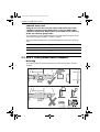
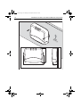
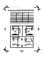
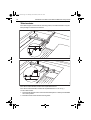
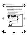
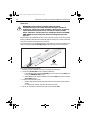
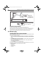
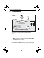
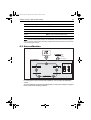
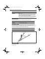
87075_2.book Page 19 Thursday, November 22, 2007 8:07 AM
Chapter 2: Installing the system
19
3. Drill two 6 mm (1/4”) diameter clearance holes through the center line of the tiller
at the positions marked.
4. Attach the tiller bracket using two 6 mm (1/4“) diameter bolts, nuts and washers.
5. Fix the bolts in position using two-part epoxy adhesive.
6. When the epoxy is completely hardened, fully tighten the nuts.
m
7m
(18
in)
45
D8815_2
90 degrees
2.6 Connecting power & drive cables to the Course
Computer
Power supply
The SPX-5 Tiller system needs a 12 V dc supply.
CAUTION: Ensure correct supply voltage
Do NOT connect 24 V to the Course Computer, or damage to the
product could occur.
Circuit breaker/fuse
Protect the power supply for the SPX-5 Tiller system with a 10 A fuse or circuit
breaker.
Cable
Using the information given at Power cable requirement on page 8, obtain the
required length of the appropriate cable to connect power from the boat’s distribution
panel to the Course Computer.