1
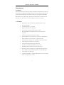
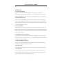
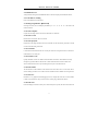
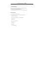
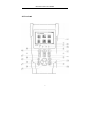
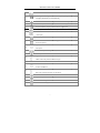
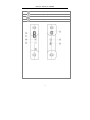
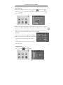
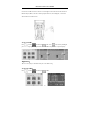
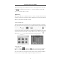
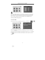
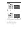
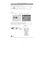
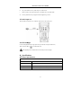
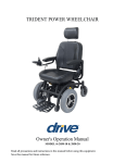
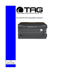
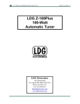
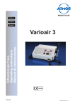
IP/CCTV Tester Manual V2.10 CAMERA WIZARD II TESTS IP CAMERA TESTS IP address scan: Scan IP cameras and network device’s for IP address Link monitor: Displays all IP addresses for a given gateway Port flicker: Blink a port’s link LED to identify cable location PING test: Search for IP address to verify connectivity POE tester: Displays PoE voltage CAT5/6 cable tester: Performs a pairs test on CAT5/6 cables Note: IP video image is not displayed on LCD CCTV CAMERA TESTS Video image display: 3.5" LCD with 960x240 resolution Video signal level meter: Display peak to peak value PTZ camera controls for numerous camera types RS485/RS422 input and data logging 3.5mm audio input Built in speaker Color bar signal generator BNC input with 3' M-to-M BNC pigtail POWER AND ACCESSORIES Up to 11 hour battery life 4 hour recharge time 12VDC 1A output to power camera with 3’ pigtail 5VDC 2A AC adaptor powers and charges tester Li-ion 3.7V 3000mAh rechargeable battery (replacement battery available) Carrying case included Contents 1、Safety information .................................................................................................................................1 2、Introduction............................................................................................................................................2 2.1 General ........................................................................................................................................2 2.2 Features .......................................................................................................................................2 2.3 Function ......................................................................................................................................3 2.3.1 Video signal testing (CCTV) ........................................................................................ 3 2.3.2 Video signal level test (CCTV)..................................................................................... 3 2.3.3 PTZ controller (CCTV) ................................................................................................. 3 2.3.4 Enhanced Color bar generator (CCTV) ........................................................................ 3 2.3.5 DC12V 1A output power (CCTV) ................................................................................ 3 2.3.6 Audio testing (CCTV) ...................................................................................................3 2.3.7 Cable tester (CCTV AND IP) ....................................................................................... 3 2.3.8 RS485 Data Test (CCYV)............................................................................................. 4 2.3.9 PTZ address scanning (CCTV) ..................................................................................... 4 2.3.10 Image magnification(CCTV) ................................................................................... 4 2.3.11 Video snapshot (CCTV).............................................................................................. 4 2.3.12 Video record (CCTV) ................................................................................................. 4 2.3.13 Video playback (CCTV) ............................................................................................. 4 2.3.14 Port flicker (IP) ...........................................................................................................4 2.3.15 IP address scan (IP) .....................................................................................................4 2.3.16 Link monitor (IP) ........................................................................................................4 2.3.17 PING test (IP)..............................................................................................................4 2.3.18 POE tester (IP) ............................................................................................................4 2.3.29 LED flashlight .............................................................................................................5 2.3.20 F1、F2 User-defined shortcut keys ............................................................................ 5 2.4 Accessories..................................................................................................................................5 2.5 Front Panel ..................................................................................................................................6 3、Operation .............................................................................................................................................10 3.1 Installing the Battery .................................................................................................................10 3.2 Quick tester connection for CCTV use.....................................................................................11 3.3 OSD Menu ................................................................................................................................11 3.3.1 PTZ controller .............................................................................................................12 3.3.2 Color-bar generator .....................................................................................................15 3.3.3 Video in level ..............................................................................................................15 3.3.4 PTZ address search ..................................................................................................... 16 3.3.5 10x zoom image display and Video out......................................................................17 3.3.6 Photograph ..................................................................................................................17 3.3.7 Video record ................................................................................................................18 3.3.8 Record playback ..........................................................................................................18 3.3.9 PING Test....................................................................................................................19 3.3.10 Cable tester ................................................................................................................19 3.3.11 Port flicker .................................................................................................................20 3.3.12 Link monitor..............................................................................................................20 3.3.13 IP address scan ..........................................................................................................21 3.3.14 PoE tester ..................................................................................................................21 3.3.15 Data monitor..............................................................................................................22 3.3.16 Time setup .................................................................................................................23 3.3.17 Device (tester) setup..................................................................................................23 3.3.18 USB ...........................................................................................................................24 3.4 DC12V 1A power output ..........................................................................................................24 3.5 Audio input test .........................................................................................................................25 3.6 LED flashlight ...........................................................................................................................25 4、Specifications.......................................................................................................................................25 4.1 General Specifications ..............................................................................................................25 IP/CCTV Tester User’s Manual 1、Safety information Notice The tester is intended to be used in a responsible and safe manner and not in areas where the use of electrical instruments could be dangerous (hospitals, gas stations etc.). The tester should be kept dry. Dust and liquid should be avoided. Like any instrument, treat carefully. Avoid dropping . Don’t leave the tester alone when charging. If the battery is hot, the tester should be disconnected from the electric source. The tester should not be charged for more than 8 hours. Don’t use the tester where the humidity is high. Once the tester is damp, power off immediately and move it away from other connected cables. The tester should not be used in the environment with the flammable gas. Do not disassemble the instrument, since no component inside can be repaired by the user. If the disassembly is necessary, please contact the factory. The instrument should not be used in an environment with strong electromagnetic interference. Do not touch the tester with wet hands. Do not use detergent to clean. Instead, use a dry cloth. If the dirt is not easy to remove, a soft cloth with water or neutral detergent can be used. Limited Warranty Byte Brothers test equipment warrants to the original consumer that this product is in good working order for a period of one year from the date of purchase. During the period this product will be repaired or replaced without charge for either parts or labor unless this unit has been damaged by the user. Repair or replacement as provided under this warranty is the exclusive remedy of the purchaser. 1 IP/CCTV Tester User’s Manual 2.Introduction 2.1 General The Camera Wizard II IP/CCTV tester is designed for the installation and maintenance of IP and CCTV cameras and devices. CCTV tests: Video display, PTZ control, DC12V output power, audio test, color generator, RS485 data decoding, picture and video recording, and image magnification. IP camera tests: IP address scanning, PING testing, Link monitor, POE measurement, Port flicker and CAT5/6 cable testing. Note: The color LCD screen will only display CCTV images (not IP images). 2.2 Features High definition 3.5”TFT-LCD color display, 480(RGB)x320 (CCTV only) Built-in LED flashlight User-defined shortcut keys(F1 and F2) Support for both NTSC/PAL video formats 10x zoom feature to magnify the video image (CCTV only) Record and playback CCTV snapshots and videos using a micro SD card (removable). IP address scan to determine an IP camera’s IP address PING an IP address to verify the connectivity of IP cameras or network devices POE measurement to test the PoE switch’s voltage to the IP camera Port Flicker blinks a switch port’s link LED. Perfect for tracing cable locations. Cable testing jack to test the pairs of a CAT5/6 cable. Link monitor to display IP address usage on the network. PTZ address scan to determine the address of a CCTV camera. RS232/RS485/RS422 communication link to drive the PTZ unit. PTZ testing for cameras so equipped. Driver supports more than thirty protocols. DC12V 1000ma power output to temporarily power CCTV camera during test. Audio input jack to test audio signals Lithium Ion Polymer Battery . This power-efficient battery can last 11 hours during normal use. Charging time is 4 -5 hours. 2 IP/CCTV Tester User’s Manual 2.3 Functions 2.3.1 Video signal display Display the CCTV image on the built-in high definition 3.5”LCD-TFT 480(RGB)x320 full-view display color screen. Supports PAL/NTSC. The LCD screen brightness/contrast/color and saturation are adjustable. Note: The color LCD screen will only display CCTV images (not IP images) 2.3.2 Video signal level test Test the CCTV video signal strength (attenuation). Longer video cables cause the image to dim and reduces the image’s dynamic range. If the video signal is too strong, it will cause a virtual shadow and reduce the sharpness of the image. The level test also displays the video level value and, if out of range, a notice will be displayed on the screen. 2.3.3 PTZ controller While displaying the CCTV image, this feature pans, tilts and zooms the PTZ base, if the camera is so equipped. The tester emulates many common PTZ protocols and sets up the controlling parameters like protocol, communication port, baud rate, PTZ ID and pan/tilt speed. These parameters can be stored and recalled (“preset” positions). 2.3.4 Enhanced Color bar generator The video generator is a PAL/NTSC multi-system color bar video generator used to test the security system’s video monitors. With the video generator, you can judge whether the color is different because of the transmission loss or interference. 2.3.5 DC12V 1000ma output power Power the CCTV camera with the DC12V (1A) power output from the tester. This is helpful during installation when camera power might not be available. 2.3.6 Audio testing Test the audio input from pickup devices. Connect the tester and pickup device with the audio cable. 2.3.7 Cable tester Test a CAT5/6 cable’s pinouts by using the cable test jack (UTP/SCAN) and the included remote. Connect the CAT5/6 cable to the cable test jack. Connect the remote on the far end of the cable. The cable test results show the pin-to-pin termination of the wires. 3 IP/CCTV Tester User’s Manual 2.3.8 RS485 data test Analyze the data coming from a RS485/RS422 device. The data is displayed in hexadecimal format. 2.3.9 PTZ address scanning Discover the address of the PTZ camera. 2.3.10 Image magnification(10xZoom) Set image 10x zoom, can view and display the details by 1x、2x、3x、4x、5x、6x – 10X zoom in the monitor and tester. 2.3.11 Video snapshot Capture the video image and save the current video frames as a JPEG file 2.3.12 Video record Record and save the current video on a SD card. 2.3.13 Video playback Playback the video images that have been saved on the SD card. The file directory name that is created is based on the date setting of the tester. 2.3.14 Port flicker Use this feature to blink the link LED on a switch port. Perfect for tracing the location of a cable that is terminated into a live switch port. 2.3.15 IP address scan Quickly determine a camera’s IP address with the IP address scan feature. The IP address scan steps through every possible address in the network’s subnet to determine the IP camera’s address. The subnet is entered into the tester as part of making the tester a part of the same network . 2.3.16 Link monitor The link monitor lists the IP address of all network devices that it discovers in its own subnet. This is useful in making sure there is not a conflict with new IP addresses that are added to an existing network. 2.3.17 PING test PINGING is a very popular network debugging tool. First, configure the tester with its own IP address to make it a network device, then you use the tester to contact (ping) other Ethernet devices. 2.3.18 POE tester Detect and display the existence of PoE power. When PoE power is present, the tester will measure and 4 IP/CCTV Tester User’s Manual display the voltage that the PoE switch or injector is supplying to the IP camera. 2.3.19 LED flashlight Light up the workspace with the ultrabright LED on the front of the tester. 2.3.20 F1, F2 User-defined shortcut keys The user-defined shortcut keys can be setup to do your most popular tests. 2.4 Accessories 1). IP/CCTV camera and device tester 2). Power Supply: DC5V 1.2~1.5A(with included USB cable) 3). Cable test remote adaptor 4). Lithium Ion Polymer Battery(3.7V DC 3000mAh ) 5). BNC cable 6). RS485 cable 7). CCTV camera power cable 8). Audio cable 9). Safety cord 10). Tool bag 11). Instruction Manual 5 IP/CC CTV Tester User’s Manual 22.5 Front Pan nel 6 IP/CC CTV Tester User’s Manual 1 OSD menu The charge indiccator: it lights red while w the battery is being b charged. As th the charging 2 is complete, the indicator turns off automatically 3 The data-transm mission indicator: it lights l red while the data is being transm mitted 4 The data-receptiion indicator: it ligh hts red while the datta is being receivedd 5 The power indiccator: it lights green n while the tester is powered p on 6 Set key, press it to enter sub-menu to set the parameterrs of functions Press more than 2 seconds, turn on or off the device ,sh hort press to turn onn or off the 7 menu display 8 Confirm/Open : Confirm the setting g of parameters;op pen or enlarge the aaperture Return/Close : Return R or cancel wh hile setting parameteers of the menu, cloose or 9 decrease the apeerture Upward: Select the item which willl be set or add the value v of the parametter. Tilt the 10 PTZ upward 11 User-defined key(User setting fun nction, the default iss “PTZ controller”) ) 12 LED Lamp Rightward,Enteer the sub-menu or select the parameteer whose value will be changed. 13 Add the value of the parameter. Pan n the PTZ right 14 Number not used Downward: Seleect the item which will w be set or reducee the value of the paarameter. 15 Tilt the PTZ dow wnward Leftward: Enter the sub-menu or seelect the parameter whose w value will bee changed. 16 ue of the parameter. Pan the PTZ left Reduce the valu 17 Record CCTV videos v 18 Snapshot(captu ure CCTV video im mage) 19 10xzoom CCTV V images on screen and video out 20 WIDE: zoom in the image 7 IP/CCTV Tester User’s Manual 21 Near focus: Focus the image nearby 22 Far focus: Focus the image faraway 23 Menu key 24 TELE: zoom out the image 8 IP/CC CTV Tester User’s Manual 26 Vid deo input (BNC inp put interface): Inputts the video 27 Vid deo output (BNC ou utput interface): Ou utputs the video 28 Nu umber not used 29 Ou utput DC12V1A pow wer, for provisionall DC test supply 30 RS S232 interface: RS232 communication for the PTZ 31 LE ED lamp 32 RS S485/422 Interface: RS485/RS422 com mmunication for the PTZ 33 Neetwork cable /Teleph hone cable interfacee test 34 US SB data /charge inteerface 35 Reemovable Micro SD D card 36 Eth hernet power supply y output/Network teesting interface 37 Eth hernet power supply y input interface 38 Au udio input: Test the camera’s audio pickup and other audio o equipment 39 Reeset the default settin ngs of tester 9 IP/CC CTV Tester User’s Manual 33、Operatio on 3.1 Installin ng the Battery y The tester has a built-in lithium ion n polymer rechargeeable battery. The ba attery (inside the baattery compartment) is i disconnected for safety s during transp portation. Prior to using th he tester, open the battery b compartmen nt and connect the battery. There is no neeed to disconnect the battery during norm mal use. Pressing key powers on an nd off the tester. y use the battery ch harger that comes with the device Notice:Only The first timee you use the tester, allow the battery to o completely dischaarge. Then rechargee the battery (4 to 5 hours for full rechaarge). This extends the life of your battery. The Charge In ndicator lightts red when chargin ng the battery, then turns t off automaticaally when the charrging is complete. Notice: Wh hen the Charge Indiccator turns offf, the battery is app proximately 90% charged. Th he charging time can n be extended for ab bout 1 hour. Avoid charging the batterry more thaan 8 hours. Press the sm mall RESET button n on the left side of the t tester to restore the factory’s defauult setttings (when the insstrument works abn normally). 10 IP/CC CTV Tester User’s Manual 33.2 Quick Tesster connectio on for CCTV use Connectt the CCTV camera’s video output to th he tester’s VIDEO IN I jack. The imagee will display on o the tester screen. Note” IP camera images will not disp play on the screen. To drivee the video through the tester to a CCTV monitor or opticaal video transmittter/receiver, connecct the device to the tester’s “VIDEO OUT” jack . The videeo image will w display on the teester and monitor att the same time. To test a camera with a PTZ Z base, connect the camera’s RS485 co ontroller cable to thhe tester’s RS485 R interface (no ote the positive and negative polarity of o the cable). For RS S232 PTZ con ntrollers, connect th he cameras PTZ’s RS232 R cable to the teester’s RS232 jack. 33.3 Turn on th he tester (OSD D Menu) Press the key y Press the key y again to turn on. to turn t off. The Auto timeout durattion is set in Devicee Settings. 11 IP/CC CTV Tester User’s Manual Once the men nu appears, choose a desired tester funcction by pressing th he the key to enter the functio on and to exitt the function. In various fun nctional modes, preess the Functions thaat require data entry y (IP addresses, etc.)) are entered with th he The squares tell t you if you are on menu 1, 2, or 3 First page menu m key. Presss key to t enter the parametters. Second page menu keys. Third page menu 33.3.1 PTZ controller D Display the video in nput (CCTV) and tesst the pan, tilt and zoom z base of camerras so equipped. Preess the kkey to enter the PTZ setup men nu. Setup the controlling parameters lik ke protocol, communication portt, baud rate, PTZ ad ddress, pan/tilt speed d; set aand recall preset possitions. Iff there is no video input, the screen dissplays “No video” and a the P PTX functions canno ot be accessed.. P PTZ controller parameter p settiing Inn the “PTZ CONTR ROLLER ”mode(aas shown above,p press the 、 P Press the key P Press the key orr key y to enter the param meters. to move the yellow cursor to diffferent PTZ parameeters. to change the parameters’ p values.. Then press the key to save annd exit the menu. Iff there is no changee, press the P Press key to return to view wing the PTZ cameera’s video. to retu urn to the Main Men nu. N Note: If there is no video, v the PTZ men nu is not functional. 12 IP/CC CTV Tester User’s Manual A A. Protocol U Use the Up and Dow wn arrow keys to move m the yellow curssor to thhe “protocol ”. Seleect the protocol. Th he tester support mo ore than thhirty PTZ protocolss. Such as Pelco-D、Samsung、Yaan、LiLin、 L C CSR600、Panasonicc、Sony-EVI etc. B B. Port M Move the yellow currsor to “port” Select which of the tester’s communication ports will connect tto the P PTZ wires controllin ng the camera’s PTZ Z base (RS232/422//485). C C. Baud M Move the yellow currsor to “Baud”. Seleect the baud rate req quired by the PTZ camera. c (6600/1200/2400/480 00/9600/19200/5760 00/115200bps) D D. Address E Enter the address off the PTZ camera (0~254). This setting must match the cam mera address . E E. Pan speed: Sett the pan speed of PTZ camera (0~63) F F. Tilt speed: Set the tilt speed of PT TZ camera (0~63) G G. Set preset position (Set PS) to storre positions for lateer recall M Move the yellow currsor to “SET PS ”,set and save presett position number (1~128),Press the keey too change the value. Then press the key to save. Preess to quit. H H. Call the presett position (Go ps) M Move the yellow currsor to “Go PS”. En nter the preset you wish w to recall (1~12 28). P Press key P Press the or to change the valu ue. key to execute the presset position setting or o press return key to t to quit. Check and set the protocol p fields correectly. The address, interface i and baud, must be the same aas the CCTV camera’s PT TZ base for the test and control to work k properly. When th he parameters are enntered correctly, the testerr will control the camera’s PTZ and len ns. A Adjusting and storiing preset (“PS”) positions: p Once you u have the PTZ basee properly connecteed to thhe tester, use the following keys to move the camera’s PT TZ base: 13 IP/CC CTV Tester User’s Manual Press th he key to control c the PTZ direection of rotation. Press th he key or to switch on or o turn off the apertu ure. Press th he key or adjust the focu us manually. Press th he key or manually adju ust the zoom. 1) Set and Go o PS S Setting a PTZ locattion for later recalll (Set PS) A A. P/T/Z the cameraa to desired position n. B B. Press the key to enter the PT TZ controller submeenu. Press the key cursor to “Set PS”. Press P the P Press the to movee the keeys to select the presset position numberr. key to complete the presset position setting or o preset return the key to quit. R Recalling a preset location l (Go PS) E Enter the preset posiition. (1~128) The PTZ P camera will go o to the desired presset position. P Press the key y to enter PTZ conttroller submenu. Preess the too “GO ps”. Enter th he preset position nu umber. Then press the t enter pposition setting or key to move the yellow w cursor key y to complete the prreset key to quit. T The camera will mov ve to the preset possition immediately: Zoom the lens and the focus and iris iss aautomatically changed to the preset parameters. T Tips:Some CCTV V cameras store preset position settings that can be read on n the tester. 2) Dome cam mera menus C Check your camera manual m to see if you ur camera can storee presets. One exam mple camera will dow wnload itts preset menu to th he tester by addressiing preset position 64. 6 aa. Press the key b.Press the key c. Press the key to enter PTZ co ontroller submenu , select preset position p 64 Enter the main menu m of the PTZ cam mera 14 IP/CC CTV Tester User’s Manual O OSD Menu of Dom me (For R Reference only) A After accessing the dome d camera menu u , users can select different d functions th hrough the arrow ke keys R Refer to the dome caamera’s manual for instructions. 33.3.2 Color bar generator P Press the key y to enter the menu u. P Press the key y to select the bar generator g an nd then press the key T The Color bar generrator supports PAL / NTSC standard co olor bars. P Press the key or , move thee cursor to “Format””、“LCD display seelect”、“Type ” sellect “Format”. The testerr sends the color bars from the “Video out” port. Press thee key thhe video output form mats. 33.3.3 Video “in” ” level and LCD D adjustment P Press to the menu , presss to enter. 15 or to cchange IP/CC CTV Tester User’s Manual Use this feature to analyze the t CCTV input vid deo and auto display y the format (PAL/N NTSC). The Vid deo Level should be within the indicateed range. Video leveels that are too low will result in a dim picture with reduced dynamic raange. A Video Leveel that is too high w will result in washed out picturees with decreased he tester’s LCD brightness, contrast an nd color saturation. Adjust th D Depending on the ty ype of camera conneected to the CCTV tester, t the Video “F Format ” will autom matically change between NTSC and PAL, and th he Video Level willl automatically chan nge between IRE (IInstitute oof Radio Engineers) and mV. NTSC sig gnals are measured in IRE units. PAL signals s are in mV. 33.3.4 PTZ addreess search P Press to seleect , press to enter. Note:Please isolate the PTZ cam mera from other PT TZ cameras before searching. s Otherwisse all the PT TZ cameras in the saame system will pan n at the same time. P Press seearch”, press fu function to seleect , and theen press to entter (as follow picturre). Select to “Adddress to select ON or o OFF, then Press disp plays on the main menu. m 16 to save. The PTZ address searchh IP/CC CTV Tester User’s Manual N Note:This function n needs to be reset each e time the tester’’s power is turned off. o P Press the key y to set the protocol, communication port, p communication n rate. The should m match thhe PTZ camera’s seettings. P Press the buttton. The tester will scan for the cameraa’s PTZ address. Ass the address is searrched, thhe PTZ camera willl pan right. Press to stop searchiing up. Press the step key to single-st thhrough the search. P Press the buttton, the tester will search for the PTZ base b address. When the address is searcched, thhe PTZ camera willl pan left. Press to stop searching g. Press M Manual search add dress: Press or to search h the address gradu ually, the image willl flash w when the address fou und. Press the direction control butto on P Press button to sing gle-step through thee search. to adjusst a Speed Dome Caamera. to quit. 33.3.5 10x zoom image i display and a Video out W When video is preseent, press to 10 0x zoom, press the button too zoom out the imag ge. Press to t see the details. Prress to zoom z in the image, ppress to quit. R Repeatedly pressing g the 10x zoom key changes the zoom 1x、2x、3x、4x、5x、6x -10X zoom m on the m monitor and the testeer screen. 33.3.6 Photograph W With video present, press the key to save the current video frame on the SD card as a JPEG G file. T The stored image is named according to o the date. The testeer automatically cheecks as to whether a SD card is installed or not. n If no SD card is installed, a “no SD D Card” message is displayed on the sccreen. 17 IP/CC CTV Tester User’s Manual 33.3.7 Video reco ord W With video present, press momeentarily. The blinkin ng icon at the top leeft, means the videoo is reecording, saving thee video to the SD caard (in AVI format)). Press again n and the blinking iicon ddisappears. The file is named according g to the date. N Note: Press the buttton for severral seconds and rellease to start, and stop s video recordin ng. 33.3.8 Record pla ayback P Press to seleect , press to enter, the lattest photograph or video v record file dissplays oon the screen. A photograph file diisplays with the P Press icon in the top rig ght corner. A video o recording displayss a to start and stop video play yback and, press to quit. In the above a image, the 3/00008 m means there is a totaal of 8 photos and viideo files, and the current c file is the thiird. Press to qu uit the latest storage image. Press to ch hoose the files. Then press to t show all the storaage files, press to enter the files, prress to choo ose the image. 18 to choose the t files. Press IP/CC CTV Tester User’s Manual 33.3.9 PING Testt C Connect the CAT5/6 6 cable to the LAN port, press enter. Press to select , and a then press to to adjust the IP address, Packet Size, Timeout, TTL L, Count. Press too adjust the parameter. Iff the IP camera or other o Ethernet equip pment is not conneccted to the tester, “connect fail ” displayys on thhe screen. In this sittuation, the sending g and receiving pack ket will be 0 and thee success rate is 0% %. Press too restart the Ping testing. With the equipment connected and a a valid IP addreess, the sending andd reeceiving packet amount will be consisttent and the successs rate will be 100%.. A Application P PING testing is one of the most conven ntional network debu ugging toools. It is useful forr verifying if the con nnected IP camera or o other nnetwork equipment is i working normally y and the IP address is correct. Itt is normal that the first data packet will be lost at the startt of the P PING testing processs. 33.3.10 Cable testter P Press to men nu , press to enter. 19 IP/CC CTV Tester User’s Manual C Connect the CAT5/6 6 LAN cable to the tester’s UTP/Scan port. p Connect the faar end of the cable tto the R Remote adapter (sho own). The cable’s wiremap w (sequence of o wires) will be dissplayed, as well as tthe seerial number of the cable tester kit. 33.3.11 Port flick ker P Press to seleect and theen press to entter. Press to start s and stop sendinng the pport LED blinking signal. This signal makes m the connected d switch port flickerr at special frequenccy. A Application: T This test is an easy way w to determine which port a LAN caable is using. 33.3.12 Link mon nitor P Press to seleect , and theen press to en nter. 20 IP/CC CTV Tester User’s Manual T The link monitor dissplays all active IP addresses a that exist on a network segm ment. Choose “start””, and ppress to start the link monitor. Iff the status is “√”, it means the IP addreess is occupied, if thhe sttatus is“×”, means the t IP address is available A Application: W When adding an IP P camera or other network n device to a network, the new w IP address mustt not be ooccupied. If two dev vices are using the same s IP address, thee equipment will no ot work properly. T The Link m monitor can quickly check if an IP addrress is occupied. 33.3.13 IP addresss scan T This could be the mo ost popular IP test on o the tester. Use it to determine the IP P address of an IP caamera. F First, connect the IP camera to the testeer’s LAN jack. If thee camera needs PoE E, connect the PoE iinto the P PSI IN jack. Press to select . Press then cursor over to o Start. Press . If the camera is found, its IP address will be displayed. d For this to t work properly, th he tester must be a the camera (you must m know the gatew way address of the camera configured to be on the same network as soo you can set the tester to have the sam me). To configure th he tester, cursor to “Set “ IP”, press thhe cursor keys . Use to give thee tester an IP addresss, mask and gatewaay address. 33.3.14 POE testeer P Press to sellect , and then t press to t enter. To test for PoE, the IP cameraa and thhe PoE power sourcce must both be con nnected to the testerr (the IP camera is what w triggers the PooE ppower source to turn n on). First connect the PoE cable to the tester’s PSE IN jaack. Then connect thhe IP camera to the tester’s LAN jack. The PO OE voltage will be displayed on the tester screen. 21 IP/CC CTV Tester User’s Manual N Note: PoE power su upply equipment ( PoE switch, PSE power supply) mu ust be connected too the teester’s PSE IN porrt so it can power the t IP camera or other o devices that are a plugged into th he teester’s LAN jack. Warning: Do not connect c POE switcches or power supp plies port to the U UTP/SCAN jack. This T will damage th he tester. 33.3.15 Data mon nitor C Connect the device to t the tester using th he RS485 or RS232 2 ports. Press too enter. Press to select , press . to set the baaud rate of RS485/R RS232 port. The tesster must match the baud raate of the device beeing analyzed. Data transfer will start automatically. a If the tester can interprett the pprotocol being sent, the tester will displlay it in the upper riight (“P: Pelco D”).. If not, “P:---“ willl display. P Press to stop the transfer. PTZ co ontrol codes from a joystick, DVR or keyboard k can also bbe ddisplayed . 22 IP/CC CTV Tester User’s Manual 33.3.16 Time setu up P Press to sellect , press Note:Press to enter. to adjust the time. Press to save. The time stamp used to nname pphotographs and vid deo is based on this time setting. 33.3.17 Device (teester) setup P Press P Press to menu m or , presss to enter. to choose the iteem, press to adjust, press to save, press too quit. A Auto power off: Set the time of auto shu ut-down. 5,10,…,60 0 minutes (of no activity). Select “Disaable” to tuurn off this feature. K Keypad tone: Turn on o or off the keypad d beep feature. L Language: ENGL LISH/ CHINESE and a other languages B Brightness: Setting the t brightness of OS SD menu and backg ground.(0~7) A Address search: off / on Open or close the t PTZ address seaarch Menu. 23 IP/CC CTV Tester User’s Manual R Restore factory settting: restore the da ata of the factory. F F1 user-defined shorrtcut key (softkey): Define this key to execute e any menu item. Press seelect, press to to t save. The defaultt setting is “ PTZ co ontroller”. F F2 user-defined shorrtcut key (softkey). Adjust as above. The default setting iss “Device setting”. 33.3.18 USB P Photographs and vid deo files can be uplo oaded to a Windows computer using th he USB jack. 33.4 DC12V 1A A power output for CCTV V cameras P Power a CCTV cam mera with the DC12V V (1A) power outpu ut from the tester. Perfect for poweringg the camera when there is no power supply available. a Notice aa. Do not connecct any power sourcee into the tester’s “D DC12/1A OUTPUT T” port. Damage willl occur. 24 IP/CC CTV Tester User’s Manual bb. Only connect the t DC12V/1A pow wer output to a CCT TV camera. c. When the CCT TV camera draws more m than 1A, the teester enters a protecttion mode. dd. For best perforrmance, fully charg ge the tester before powering p a camera.. 33.5 Audio input test T Test the audio from audio devices. Con nnect the audio device to the Audio In jack j . 33.6 LED flash hlight U Use the ultrabright LED L lamp to light up u the work space (ssee the front panel of o the tester). T Turn on the tester. Press P to turn On/Off O the LED. Note: Bright light l can be harmfull. Do not look direcctly into the LED lig ght. 44、Specifica ations 44.1 General Specifications Video Test Signal mode NTSC/PAL (Auto detect) Display 3.5 inch h digital TFT-LCD ,480(RGB)x 32 20 resolution LCD adjustment Brightn ness, Contrast, Saturration adjustable Video IN/OUT 1 chann nel BNC Input & 1 channel Output 25 IP/CCTV Tester User’s Manual Video Output Mode 1.0 Vp-p Video Level test Level test Video signals measured in IRE (NTSC) or mV (PAL) PTZ controller Communication Supports RS232 and RS485 Compatible with more than 30 protocols such as PELCO-D/P, PTZ Protocol Samsung, Panasonic, Lilin, Yaan, etc. Baud Rate 600,1200,2400,4800,9600,19200,57600,115200bps Video Signal Generation Outputs one channel PAL/NTSC color bar video signal for the testing Color bar generator of monitors or a cable’s red, green ,blue, white or black color channel. UTP Cable tester Using a Remote Adapter (included), test a CAT5/6 UTP cable. The UTP cable test pinout is displayed. DC12V 1A power output DC12V power output Output DC12V (1A) power for powering a CCTVcamera (CCTV camera) Audio input test Audio input test Test the audio devices using the Audio In port. RS485 data analysis Data Monitor Captures and analyzes the command data from controlling devices. 10x Zoom CCTV Image Image 10x zoom Zoom CCTV image display and video out signal. Photograph、Video record, Record playback Photograph Save the CCTV image as JPG file on mini SD card (included). Video record Record CCTV videos and store them on mini SD card (included) Record playback View the stored photographs and video from the mini SD card. 26 IP/CCTV Tester User’s Manual Port flicker Port flicker Blink the link LED on a switch port to locate a cable’s port location. IP scan、Link monitor、PING test IP scan Determine an IP camera’s IP address (must be on same network). Link monitor Detect IP devices on the network (check for available IP addresses). Search for IP cameras or other devices by scanning for their addresses PING testing on the network. When roundtrip time of the communication is displayed. PoE tester PoE tester Display PoE power supply voltage and cable pairs used POWER Power Adapter DC 5V(1.5A) Battery Built-in 3.7V Lithium polymer battery. 3000mAh. Rechargeable Charge time is 3-4 hours. Working time is 11 hours. Low Consumption Energy saving technology, the battery icon real-time display Setup parameters Language English/Chinese and other languages OSD menu Auto off Adjustable 5-60 (mins) or disable. Keystroke tone On/Off General Working Temperature -10℃ ~+50℃ Working Humidity 30%~ 90% Dimension/Weight 194mm x 112mm x 48mm / 540g 27 CAMERA WIZARD II MODEL VTX455 Byte Brothers, Inc nd 7003 132 Place SE Newcastle, WA 98059 (425)917-8380 FAX (425)917-8379 www.bytebrothers.com [email protected]