1
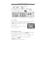
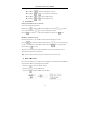
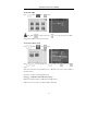
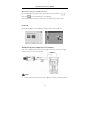
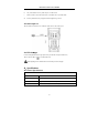
IP/CCTV Tester User’s Manual
2.3 Functions
2.3.1 Video signal display
Display the CCTV image on the built-in high definition 3.5”LCD-TFT 480(RGB)x320
full-view display color screen. Supports PAL/NTSC. The LCD screen brightness/contrast/color and
saturation are adjustable. Note: The color LCD screen will only display CCTV images (not IP images)
2.3.2 Video signal level test
Test the CCTV video signal strength (attenuation). Longer video cables cause the image to dim and
reduces the image’s dynamic range. If the video signal is too strong, it will cause a virtual shadow and
reduce the sharpness of the image. The level test also displays the video level value and, if out of range,
a notice will be displayed on the screen.
2.3.3 PTZ controller
While displaying the CCTV image, this feature pans, tilts and zooms the PTZ base, if the camera is so
equipped. The tester emulates many common PTZ protocols and sets up the controlling parameters like
protocol, communication port, baud rate, PTZ ID and pan/tilt speed. These parameters can be stored and
recalled (“preset” positions).
2.3.4 Enhanced Color bar generator
The video generator is a PAL/NTSC multi-system color bar video generator used to test the security
system’s video monitors. With the video generator, you can judge whether the color is different because
of the transmission loss or interference.
2.3.5 DC12V 1000ma output power
Power the CCTV camera with the DC12V (1A) power output from the tester. This is helpful during
installation when camera power might not be available.
2.3.6 Audio testing
Test the audio input from pickup devices. Connect the tester and pickup device with the audio cable.
2.3.7 Cable tester
Test a CAT5/6 cable’s pinouts by using the cable test jack (UTP/SCAN) and the included remote.
Connect the CAT5/6 cable to the cable test jack. Connect the remote on the far end of the cable. The
cable test results show the pin-to-pin termination of the wires.
3