1
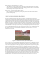
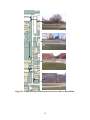
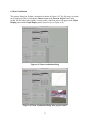
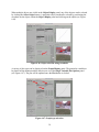
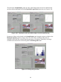
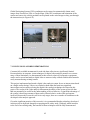
Using Digital Video Analysis
to Monitor Driver Behavior at
Intersections
Final Report
November 2006
Sponsored by
the Iowa Department of Transportation
(CTRE Project 05-214)
Iowa State University’s Center for Transportation Research and Education is the umbrella organization for the following centers and programs: Bridge Engineering Center • Center for Weather Impacts on Mobility
and Safety • Construction Management & Technology • Iowa Local Technical Assistance Program • Iowa Traffic Safety Data Service • Midwest Transportation Consortium • National Concrete Pavement
Technology Center • Partnership for Geotechnical Advancement • Roadway Infrastructure Management and Operations Systems • Statewide Urban Design and Specifications • Traffic Safety and Operations
About CTRE/ISU
The mission of the Center for Transportation Research and Education (CTRE) at Iowa State University is to develop and implement innovative methods, materials, and technologies for improving transportation efficiency, safety, and reliability while improving the learning environment of
students, faculty, and staff in transportation-related fields.
Disclaimer Notice
The contents of this report reflect the views of the authors, who are responsible for the facts
and the accuracy of the information presented herein. The opinions, findings and conclusions
expressed in this publication are those of the authors and not necessarily those of the sponsors.
The sponsors assume no liability for the contents or use of the information contained in this
document. This report does not constitute a standard, specification, or regulation.
The sponsors do not endorse products or manufacturers. Trademarks or manufacturers’ names
appear in this report only because they are considered essential to the objective of the document.
Non-discrimination Statement
Iowa State University does not discriminate on the basis of race, color, age, religion, national
origin, sexual orientation, gender identity, sex, marital status, disability, or status as a U.S.
veteran. Inquiries can be directed to the Director of Equal Opportunity and Diversity,
(515) 294-7612.
Technical Report Documentation Page
1. Report No.
CTRE Project 05-214
2. Government Accession No.
4. Title and Subtitle
Using Digital Video Analysis to Monitor Driver Behavior at Intersections
3. Recipient’s Catalog No.
5. Report Date
November 2006
6. Performing Organization Code
7. Author(s)
Derrick Parkhurst
8. Performing Organization Report No.
9. Performing Organization Name and Address
Center for Transportation Research and Education
Iowa State University
2711 South Loop Drive, Suite 4700
Ames, IA 50010-8664
10. Work Unit No. (TRAIS)
12. Sponsoring Organization Name and Address
Iowa Department of Transportation
800 Lincoln Way
Ames, IA 50010
11. Contract or Grant No.
13. Type of Report and Period Covered
Final Report
14. Sponsoring Agency Code
15. Supplementary Notes
Visit www.ctre.iastate.edu for color PDF files of this and other research reports.
16. Abstract
Commercially available instruments for road-side data collection take highly limited measurements, require extensive manual input, or
are too expensive for widespread use. However, inexpensive computer vision techniques for digital video analysis can be applied to
automate the monitoring of driver, vehicle, and pedestrian behaviors. These techniques can measure safety-related variables that cannot
be easily measured using existing sensors. The use of these techniques will lead to an improved understanding of the decisions made by
drivers at intersections. These automated techniques allow the collection of large amounts of safety-related data in a relatively short
amount of time. There is a need to develop an easily deployable system to utilize these new techniques.
This project implemented and tested a digital video analysis system for use at intersections. A prototype video recording system was
developed for field deployment. A computer interface was implemented and served to simplify and automate the data analysis and the
data review process. Driver behavior was measured at urban and rural non-signalized intersections. Recorded digital video was
analyzed and used to test the system.
17. Key Words
driver behavior—non-signalized intersections—traffic safety—video analysis
18. Distribution Statement
No restrictions.
19. Security Classification (of this
report)
Unclassified.
21. No. of Pages
22. Price
53
NA
Form DOT F 1700.7 (8-72)
20. Security Classification (of this
page)
Unclassified.
Reproduction of completed page authorized
USING DIGITAL VIDEO ANALYSIS TO MONITOR
DRIVER BEHAVIOR AT INTERSECTIONS
Final Report
November 2006
Principal Investigator
Derrick Parkhurst
Assistant Professor, Department of Psychology
The Human Computer Interaction Program
Iowa State University
Preparation of this report was financed in part
through funds provided by the Iowa Department of Transportation
through its research management agreement with the
Center for Transportation Research and Education,
CTRE Project 05-214.
A report from
Center for Transportation Research and Education
Iowa State University
2711 South Loop Drive, Suite 4700
Ames, IA 50010-8664
Phone: 515-294-8103
Fax: 515-294-0467
www.ctre.iastate.edu
TABLE OF CONTENTS
ACKNOWLEDGMENTS ............................................................................................................ IX
1. INTRODUCTION .......................................................................................................................1
2. DESIGN OF A VIDEO RECORDING STATION (VRS)..........................................................1
2.1 Design Constraints .........................................................................................................1
2.2 Prototype Design............................................................................................................2
2.3 Prototype Components and Cost....................................................................................3
3. DIGITAL VIDEO RECORDING PROCEDURE.......................................................................5
4. DIGITAL VIDEO ANALYSIS ...................................................................................................6
4.1 Object Detection ............................................................................................................6
4.2 Object Identification and Tracking ................................................................................8
4.3 Object Track Filtering....................................................................................................8
4.4 Object Occlusion Detection and Correction ..................................................................8
4.5 Noise Filtering ...............................................................................................................9
5. DEPLOYMENT OF DIGITAL VIDEO ANALYSIS SYSTEM AT NON-SIGNALIZED
INTERSECTIONS...............................................................................................................9
6. TRAFFIC DATA ANALYSIS APPLICATION (TDAA) USAGE GUIDE.............................15
6.1 Video Capture and Image Extraction...........................................................................16
6.2 Image Processing .........................................................................................................27
6.3 Data Visualization........................................................................................................37
7. CONCLUSIONS AND RECOMMENDATIONS ....................................................................42
v
LIST OF FIGURES
Figure 2.1. Video recording system prototype ................................................................................3
Figure 3.1. Calibration markers placed 10 feet apart.......................................................................5
Figure 5.1. A map showing four intersections chosen for study on Bissell Road .........................10
Figure 5.2. A collision diagram (1995-2005) of U.S. 69 and 190th and a corresponding video
frame ..................................................................................................................................11
Figure 5.3. Velocity profile of a vehicle coming to a complete stop.............................................12
Figure 5.4. Velocity profile of a vehicle failing to stop.................................................................13
Figure 5.5. Velocity profile of a vehicle in the far lane.................................................................13
Figure 5.6. Average velocity histogram for all object tracks.........................................................14
Figure 5.7. Multiple absolute velocity profiles..............................................................................14
Figure 6.1. TDAA master dialog box ............................................................................................16
Figure 6.2. Capture options dialog.................................................................................................17
Figure 6.3. Choose project dialog..................................................................................................17
Figure 6.4. Choose dialog—project selected .................................................................................18
Figure 6.5. Video source selection dialog......................................................................................18
Figure 6.6. Video source from Digital Video (DV) file selected ..................................................19
Figure 6.7. Digital video file dialog...............................................................................................19
Figure 6.8. DV file selection dialog...............................................................................................20
Figure 6.9. Frame extraction dialog...............................................................................................20
Figure 6.10. Starting frame extraction ...........................................................................................21
Figure 6.11. Checking the number of frames extracted from DV .................................................21
Figure 6.12. Video source from individual images previously extracted from DV ......................22
Figure 6.13. Image location dialog ................................................................................................22
Figure 6.14. File dialog for choosing a starting file for extraction................................................23
Figure 6.15. Image location dialog with image prefix and path indicated ....................................23
Figure 6.16. Video Source from DV acquired directly from DV capable camera ........................24
Figure 6.17. Setup Camera panel—connect camera......................................................................24
Figure 6.18. Find Starting Frame panel—rewind or fast forward camera.....................................25
Figure 6.19. Capture Video panel—start the video data transfer ..................................................25
Figure 6.20. Digital video capture progress dialog........................................................................26
Figure 6.21. Frame Extraction dialog for direct DV camera input................................................26
Figure 6.22. Playing a selected video from the Capture Options dialog .......................................27
Figure 6.23. Video replay dialog ...................................................................................................27
Figure 6.24. Data analysis dialog...................................................................................................28
Figure 6.25. Object detection parameter dialog.............................................................................28
Figure 6.26. Background selection dialog .....................................................................................29
Figure 6.27. Selecting upper-most boundary (limit) for object detection .....................................29
Figure 6.28. Upper-most area shaded in gray ................................................................................30
Figure 6.29. Lower-most area shaded in gray ...............................................................................30
Figure 6.30. Selection of background image without vehicles......................................................31
Figure 6.31. Selection of first frame for processing ......................................................................31
Figure 6.32. Selection of last frame for processing .......................................................................32
Figure 6.33. Detecting objects in video .........................................................................................32
Figure 6.34. Object detection completed .......................................................................................33
Figure 6.35. Review results dialog for object detection step.........................................................33
vii
Figure 6.36. Object identification parameter setting dialog ..........................................................34
Figure 6.37. Identify objects in video ............................................................................................34
Figure 6.38. Review results dialog following object identification...............................................35
Figure 6.39. Correct object shape in video ....................................................................................35
Figure 6.40. Review results dialog with and without shape correction.........................................36
Figure 6.41. Detect and correct vehicle–vehicle occlusions in video............................................36
Figure 6.42. Data visualization dialog ...........................................................................................37
Figure 6.43. Data visualization dialog after project loaded...........................................................37
Figure 6.44. Object examination using frame slider bar................................................................38
Figure 6.45. Object selection using object number slider bar or text entry box............................38
Figure 6.46. Object selection using crosshairs ..............................................................................39
Figure 6.47. Graph type selection..................................................................................................39
Figure 6.48. Visualization with and without shape correction and filtering .................................40
Figure 6.49. Histogram generation ................................................................................................40
Figure 6.50. Multiple vehicle graph based on selected histogram range.......................................41
Figure 6.51. Vehicle selection using the multiple vehicle graph...................................................41
Figure 6.52. Combined camera and aerial view of a rural intersection .........................................42
viii
ACKNOWLEDGMENTS
The authors would like to thank the Iowa Department of Transportation for sponsoring this
research.
ix
1. INTRODUCTION
Commercially available instruments for road-side data collection take highly limited
measurements, require extensive manual input, or are too expensive for widespread use.
However, inexpensive computer vision techniques for digital video analysis can be applied to
automate the monitoring of driver, vehicle, and pedestrian behaviors. These techniques can
measure safety-related variables that cannot be easily measured using existing sensors.
This project implemented and tested a digital video analysis system for use at intersections based
on a single camera design. As part of the research effort, a prototype video recording system was
developed for field deployment. It was designed around the objective of recording high-quality
video at an intersection for up to one week without any intervention. The design of this system is
described in Section 2. To simplify the analysis of the recorded video, a standard camera–
intersection configuration was adopted. This configuration is described in Section 3. The
algorithms used to track objects in the digital video and their implementation are described in
detail in Section 4. Video was recorded at both urban and rural non-signalized intersections and
was analyzed using the digital video analysis techniques developed in this project. These
intersections and analysis results are described in Section 5. A graphical computer interface was
implemented in order to simplify and automate the data analysis and the data review process. A
step-by-step guide to the usage of this software is provided in Section 6.
2. DESIGN OF A VIDEO RECORDING STATION (VRS)
The primary advantage of digital video analysis is the ability to automatically track vehicles and
quantify the frequency of events over a long period of time. In this research, a low-cost digital
camcorder is used to collect video from non-signalized intersections. The recorded video is used
to test the feasibility of using digital video analysis for traffic safety studies. The video taping
sessions were limited to a maximum length of one hour due to the storage limits of current
camcorder technology. Because the recording of video does not require any attention, it would
be desirable to have the capability to record video for much longer periods of time.
2.1 Design Constraints
In order to develop this capability, a portable video recording station was designed around the
objective of recording high-quality video for up to one week (168 hours) without any
intervention. This design constraint was given the highest priority. The second most important
design constraint was to find a low-cost solution through the use of consumer-grade off-the-shelf
parts and open-source software. While satisfying these two objectives alone is not particularly
challenging, the design problem became much more challenging when a third design constraint
was enforced. Because power is not typically available along the road or at all intersections, we
required that the station be completely self powered for the one-week recording period.
Satisfaction of these three design constraints made the problem much more difficult, as it forced
consideration of the tradeoffs between low-power and low-cost hardware as well as the tradeoff
between battery and solar power. A number of additional design constraints were enforced.
1
Some of these constrains were that the stations should be capable of operating both during the
day and the night, that the stations should be mobile, and that the station should be weather
resistant and capable of running across a wide range of temperatures. Furthermore, we focused
on making the production process scalable; thus, we used only commonly available parts that
could be easily assembled with minimal work where possible. We also have focused on a
modular approach that utilizes components that are easily swappable to allow for easy repair or
replacement.
2.2 Prototype Design
Given that no known consumer–grade solution is available for recording one week of video, we
relied upon the use of a general purpose computer. To minimize power constraints, we needed a
computer that was designed for minimal power consumption. While using a laptop was a
possibility, laptops are relatively expensive, not sufficiently customizable, and include features
not necessarily relevant to the current application. Therefore we went with a specialized
motherboard and central processing unit (CPU) designed for low-power embedded applications.
The motherboard comes with a high-efficiency DC to DC converter designed to regulate voltage
and current supplied to the motherboard when powered by a 12-volt battery, as is typical in
automotive applications. The CPU and power supply are both fanless and do not require active
venting.
While the majority of embedded systems available today utilize specialized architectures, this
motherboard and CPU are compatible with the x86 architecture. This minimizes the amount of
specialized software required for development of applications using this hardware and enables
the use of the open-source operating system Linux. Linux is highly customizable and can be
configured to run in a low power consumption mode. While some specialized software was
written in C to manage the video capture, memory buffering, and file writing operations, the
video capture card drivers were open source.
In order to record one week of video with a reasonable video compression rate, a 250 gigabyte
hard drive is required. A standard desktop computer hard drive was selected in combination with
a swappable hard drive system such that the digital video could easily be removed from the
recording station and inserted into another computer for data analysis. Although a laptop hard
drive is designed to consume less power than a desktop hard drive, the cost is significantly
greater. The operating system software can be customized to minimize the power consumption
of the hard drive by caching video in memory and spinning down the hard drive in between
writes from memory. The hard drive has all software preloaded such that the computer boots
from the hard drive and immediately begins recording video.
Analog, rather than digital, cameras were chosen as the most appropriate solution to capture
video. They are low power, low cost, ruggedized, and the camera that we selected is preequipped with infrared light-emitting diodes for active illumination of the scene at night. An
analog to digital video capture card is required for use of this camera. The capture card converts
the video into a MPEG compressed format using a specialized digital signal processor, thus
minimizing the processing load and power consumption of the CPU.
2
The most constraining aspect of the design was finding a power source capable of supporting a
running time of one week that was both low cost and mobile. While a solar power solution was
considered feasible and could allow the system to run more than one week, that approach suffers
a number of limitations. First, the complexity and price of the system would be unacceptably
increased. The lack of light at night and during certain weather conditions would necessitate both
an onboard battery and charging system. Continuous video recording could not be guaranteed.
Furthermore, interaction with the system will already be periodically required in order to collect
the digital video for analysis. Therefore, the system was designed to run completely on batteries.
Given the power consumption ratings of the processing hardware and the one-week desired
running time, four high-capacity deep-cycle marine batteries are necessary.
A weatherproof case was selected to house the motherboard, hard drive, and power converter.
This case allows for mounting of the swappable drive bay to support easy removal and insertion
of hard drives. The batteries are housed in individual weather-proof polypropylene cases. The
camera is already ruggidized and is affixed atop a four-foot pole extending out from the base.
Figure 2.1 shows a photograph of the computer components and camera and two cut-away
computer-aided design (CAD) diagrams of the complete system.
Figure 2.1. Video recording system prototype
2.3 Prototype Components and Cost
The prototype design presented in the previous section is the lowest cost solution that meets all
of the other design constraints. The overall cost was minimized by using consumer-grade offthe-shelf parts repurposed for the task of video recording. The parts for this system can be
acquired for an approximate total of $1,100 when purchasing the components individually.
However, it is expected that the cost could be reduced if bulk purchases were made. The
construction time is on the order of 10–15 hours, but because the design is simple and assembly
is straightforward, the associated labor costs are expected to be minimal. The remainder of this
section provides a list of the necessary components and their prices.
Motherboard—VIA EPIA CN10000EG Fanless Mini-ITX Mainboard, $185.00
This motherboard is well suited to this application because it does not consume much power
or produce much heat. Any heat generated by the system is dissipated through a heat sink in
3
the center of the board. It has a PCI slot for the capture card and is one of the smallest form
factors available.
Memory—AMPO 512MB 240-Pin DDR2 SDRAM 533 (PC2 4200), $40.00
This is the amount and type of random access memory (RAM) necessary for this
motherboard and application. Although less RAM would minimize cost, this amount will
allow for buffering of video in memory. Buffering of video will minimize the amount of
time that the hard drive will need to spin and reduce power consumption.
Video Capture Card—Hauppauge 980 Personal Video Recorder, $130.00
This video card has onboard compression and is well supported under the open-source
operating system Linux. This solution for video capture removes the burden of image
capture and conversion to the MPEG video format from the CPU and thus helps to minimize
power consumption. However, the fact that the card requires a PCI card limits the range of
motherboards that are compatible and is slightly more expensive than other video capture
solutions.
Case—12 VDC Weatherproof Enclosure with Mounting Plate, $150.00
This enclosure is weather rated and was intended for use with outdoor electronic devices. It
is large enough to fit all of the computer components. An internal mounting board can be
configured to support a mini-itx motherboard, power supply, and hard drive.
Hard Drive—Western Digital Caviar SE WD2500JS 250GB SATA, $80.00
Given a reasonable MPEG compression, this size hard drive will be sufficient to hold seven
days worth of digital video. A desktop hard drive rather than a low-power laptop hard drive
is used in order to minimize the cost.
Hard Drive Swap Kit—SanMax PMD-96I Black Mobile Hard Drive Rack, $20.00
The hard drive will be mounted using this rapid swap kit to support easy removal.
Camera—Color Infrared Day/Night Sony Super HAD CCD Camera - $120.00
This camera provides an excellent picture during the day while using almost no power. At
night, a high-efficiency infrared LED array activates automatically, which allows video to
be recorded while still consuming very little power. It has a rated night-time seeing distance
of 50 feet.
Power Converter—Automotive 90W DC-DC Power Supply, $80.00
This power converter takes a 12 VDC input and produces a regulated 12 and 5 volt output
necessary to power the motherboard, hard drive, and camera. The converter has an 80 to 90
percent efficiency rating.
Batteries—4 Interstate SRM-27B 12 VDC batteries, $350.00
These are deep-cycle marine batteries designed to sustain cycles of full charge to complete
discharge. It is estimated that four batteries will power the system for seven days under
nominal conditions. Temperature, battery usage and discharge, and charging rate will affect
the total running time.
4
Battery Charger—BatteryMinder 12117, $50.00
This charger has a large enough capacity while also providing functions that can enhance
battery life, such as desulfation and over/under charging protection. It has a visual monitor
that tells charge state and quick-connect cords.
Battery Cases—4 Group 27 Battery Boxes, $45.00
These vented boxes are designed to provide good protection from the elements and also
provide mounting straps.
3. DIGITAL VIDEO RECORDING PROCEDURE
In order to simplify the digital video analysis procedures, a standard camera–intersection
configuration was adopted. The standard configuration requires that a single digital video camera
is placed 50 feet from the lane of interest. The camera should be mounted on a secure tripod in
order that the system stays fixed and is not perturbed by small gusts of wind. The camera height
should be set to 4 feet. The rotation of the camera must be set such that the view direction of the
camera is perpendicular to the lane of interest. The camera position parallel to the lane of interest
is unconstrained. For the study of intersections, it was found ideal to position the control device
(e.g., stop sign) approximately in the center of the camera’s field of view. An image taken from
the camera’s point of view in the standard configuration is shown in Figure 3.1 for a nonsignalized four-way stop.
Figure 3.1. Calibration markers placed 10 feet apart
Once a camera is set up in the standard configuration at an intersection, a calibration procedure
must be followed. This procedure allows the digital video analysis to estimate distances in the
scene (in feet) using distances in the images (in pixels). The procedure requires that two planer
markers are placed within the camera’s field of view along the intersection of interest. Each
marker is an 8.5 inch by 11 inch checkerboard pattern printed onto a rigid material and mounted
to a tripod. A checkerboard pattern is used so that the digital video analysis can precisely locate
the marker at the sub-pixel level. The markers must be set up parallel to the lane of interest and
as close as possible to the lane of interest. Although the optimal calibration process would place
the calibration markers in the center of the lane of interest, practically, this can be difficult. It
was found that placing the markers just outside of the lane of interest was sufficient for vehicle
tracking purposes. The distance between the checkerboard centers must be set as close as
5
possible to 10 feet. Only a single video frame is needed with the un-occluded markers for the
calibration. The markers need not stay in place for the entire duration of the video. The
calibration process can be completed at any time during the video recording as long as the
camera remains fixed throughout.
Once the calibration process is completed, a conversion factor between distance in pixels in the
camera image and distance along the calibration plane in the scene can be determined. However,
the factor resulting from this calibration is only an approximation. Deviations from this
conversion factor are expected when the tracked objects do not lie on the calibration plane (i.e.,
the objects are closer or farther), or when the tracked objects are on the calibration plane, but
distant from the location of the markers (i.e., just entering or leaving the image frame). For the
purposes of vehicle tracking in the lane of interest, these deviations are minimal. A calibration
process involving more markers placed at a range of known camera depths could be used to
minimize this error if needed for a particular application. This approach was avoided in order to
make usage of this tool as simple as possible without introducing an unreasonable amount of
error.
4. DIGITAL VIDEO ANALYSIS
The digital video analysis begins with a frame by frame extraction of objects in the scene. These
objects are extracted by comparison of each frame with an image of the scene that does not
contain any objects of interest (i.e., vehicles). Then, a position-based criterion is used to link
objects across frames in order to create object tracks. The object tracks are analyzed to determine
object identity (i.e., vehicle, pedestrian). A dynamic occlusion detection and correction analysis
is conducted in order to uniquely identify each object in the scene and correct the estimated
object center of mass. The output of the analysis is a dataset containing the position, velocity,
size, and identity of each detected object in the scene. The following sections describe the steps
of this process in more detail.
4.1 Object Detection
The output of the object detection stage is an object detection list. This is a list of all detected
objects in each video frame that specifies the position and size of each object. Because a singlecamera approach is taken in this research, it must be assumed that the detected objects are on or
near the calibration plane. Thus, the positional information is limited to horizontal and vertical
position estimates, and the size estimates of the vehicle refer only to the side profile of the
object.
Each frame of the recorded digital video is extracted to a separate image. Each image is then
point-wise compared to an image of the scene that does not contain any objects of interest. This
image is referred to as the background image. Prior to proceeding with object detection, the user
should select a single frame from the video that does not contain any objects of interest or any
other moving objects. While an automatic background selection algorithm is available to the
user, the algorithm is relatively slow and will not guarantee that the image does not contain any
6
objects of interest. It will only guarantee to find images without moving objects. The automatic
algorithm will select scenes where vehicles are temporarily stopped. However, the user can use
the automatic algorithm and then proceed by manually selecting a different background image if
the automatic selection is inappropriate.
Each image is converted to gray scale prior to point-wise comparison between the background
image (B) and the scene image (I). The result is an intensity difference image (D). Pixels with
intensity greater than the object detection threshold θ are set to a value of 1. The rest of the
pixels are set to a value of 0. The result of this operation is an object mask image (M) that
specifies the candidate locations of objects. The threshold θ can be adjusted according to the
image noise levels of the camera in order to minimize the number of false alarms. A high θ can
also be utilized to combat false alarms due to slight movement of objects in the background. For
example, wind can cause trees or signs to move slightly.
To further reduce the sensitivity of object detection process to false alarms, a series of
morphological operations are performed on the object mask. These operations include eroding
the mask through a majority operation in order to eliminate regions that are above threshold but
too small to be an object of interest, dilating to assure that the entire object is captured within the
extent of the mask, and finally closing to create convex regions that have no holes. Given the
complexity of the point-wise comparisons and morphological operations, intensity images are
down sampled by a factor of Δ prior to processing.
Once the object mask has been computed, separate regions are identified and labeled. A
bounding box, center of mass, and area is then computed for each. Objects with an area less than
a minimum area threshold ϕ are discarded. Objects with an area between ϕ and the minimum
vehicle area threshold ν are labeled pedestrians. Objects with an area greater than or equal to ν
are labeled vehicles.
Because the light levels in the scene change with time and the object detection algorithm
depends on image intensity, any given background image will only be appropriate for use with
images that were taken at a point nearby in time. To address this problem, the background is
adapted slowly over time. For each frame f, a background image for the next frame B(f+1) is
created based on the current background image B(f), the object mask M(f), and regions of the
current image I(f) that contain no objects Mi(f), such that
B(f+1) = B(f) * β + [ B(f) • M(f) + I(f) • Mi(f) ] * (1-β),
where β is a parameter that controls the time constant of adaptation to changes in the scene, *
denotes scalar image multiplication, and • denotes point-wise image multiplication. Using this
approach, the background image is updated using the current image locations that do not contain
objects.
7
4.2 Object Identification and Tracking
The output of the object identification stage is an object track list. Each object that has been
identified across multiple frames is assigned a unique object track. Each object track is thus a list
of references to the relevant object entries in the object detection list.
In order to link together objects across frames, each object in each frame of the recorded digital
video is compared to each object in the previous frame. Those objects that are less than the
threshold horizontal distance δ apart in space and have a difference in their area less than the
threshold area difference α are considered candidate matches. For each object in the current
frame, the single best match is determined by taking the closest candidate object from the
previous frame. A reference to the object in the current frame is then added to the object track
that refers to the matched object in the previous frame.
In the case that no candidate matches are found, a new object track is added to the object track
list. All objects in the first frame of the video generate new object tracks. Objects entering the
video frame also generate new object tracks. Objects that are temporarily occluded can also
generate new object tracks upon re-appearance in the frame. Thus, the final object tracking list
may contain multiple object tracks for a single object that moves through the scene, depending
on the frequency with which the object was occluded by other objects or scene elements.
Multiple object tracks may refer to some of the same object.
4.3 Object Track Filtering
The goal of object track filtering stage is to use the object tracks to improve the estimate of the
object position, shape, and size. In the cases where an object is occluded at the edge of the scene
or by another vehicle, the estimates of the object properties are poor. These estimates can be
improved by making the assumption that the size of the object being tracked does not change
during tracking. The object size (i.e., width and height in the image) for each frame that the
object is detected can be treated as a sample. The best guess at the true object size is taken as the
mode of all of the samples. If the observed size of the object in any individual frame is greater
than σ standard deviations from the modal size, the size in that frame is reset to the modal size.
The object bounding box is then adjusted around the observed center of the object. If, however,
one edge of the object is near the edge of the image, it is assumed that the object is partially
occluded. In this case, the observed object center is a poor estimate of the true object center.
Therefore, the new bounding box is set based on the visible object boundary instead of the object
center. The object center is then adjusted according to the object boundary. This correction
allows the vehicle to be correctly tracked even when it is only partially in the frame.
4.4 Object Occlusion Detection and Correction
The goal of the object identification stage is to create an object track list where each track
uniquely corresponds to a single object in the scene, for every detected instance of the object in
the video. This requires the correct identification of the object across occlusions.
8
The first step is to detect occlusions. It is assumed that each object that enters the scene also exits
the scene. If this assumption holds, any object track that either ends or begins within the object
frame rather than at the edges of the frame can be assumed to have been occluded. Thus, the
position of the first and last object of each object track is examined. If the first object of the track
is near the image edge, the track is classified as having entered the scene. Otherwise, the track is
classified as having been occluded. If the last object of the track is near the image edge, the track
is classified as having left the scene. Otherwise, the track is classified as having been occluded
before leaving the scene.
Once the occluded object tracks have been identified, the ends of the object tracks are examined
for potential matches across occlusions. Due to the occlusion, spatial position is not a reliable
indicator of object identity. Therefore, the visual features of the object are used as a matching
measure. For each end of the object track that is occluded, a comparison is made between the
visual features of the object and the visual features of objects within λ frames.
The SIFT algorithm (Lowe 1999) is employed to match visual features from object to object.
This matching algorithm provides robust matching performance when the compared objects
differ in position, rotation, scaling, and global changes in color and intensity. Although matching
the visual features of objects is quite slow, it is more reliable than using position alone. Once
links between object tracks have been established, the object tracks are reorganized to create a
master object track list where each track uniquely describes a single scene object.
4.5 Noise Filtering
In order to minimize the effects of noise, temporal averaging is applied to the object tracks. A
noncausal boxcar filter of size τ is run across the object center and bounding box coordinates
separately. The filter size τ should be chosen based on the properties of the camera. It should be
noted that a large filter can result in an underestimation of minimum and maximum velocities.
5. DEPLOYMENT OF DIGITAL VIDEO ANALYSIS SYSTEM AT NON-SIGNALIZED
INTERSECTIONS
To obtain video that could be used to test the video analysis algorithms, the system was deployed
to a total of five intersections in Ames, Iowa. Four non-signalized intersections on Bissell Road
were chosen. The location of these intersections is shown on the map in Figure 5.1. The position
and direction of the camera in the standard camera–intersection configuration is shown with a
blue box and arrow. A video frame taken from each intersection is also shown.
A single, high-speed rural intersection at U.S. 69 and 190th was also chosen. A collision diagram
and video frame from the recording are shown in Figure 5.2.
9
Figure 5.1. A map showing four intersections chosen for study on Bissell Road
10
These intersections and camera positions were chosen in order to test the system on a variety of
backgrounds. Each background represents a different type of potential source of false alarms in
the object detection process. The first urban intersection has a large tree in the background. The
second and third urban intersections contain a view of the road crossing the lane of interest. The
last urban intersection contains a large window that reflects light from passing vehicles. Three of
the urban intersections are three-way stops, while one intersection is a four-way stop. The urban
intersections are on the Iowa State University campus and experience heavy vehicle and
pedestrian traffic during the day. Video was recorded from each intersection during the hour of
4:00 p.m., one intersection per day. Video was also recorded from a single intersection at 4:00
p.m. on four different days in the case that traffic varied as a function of day of the week. The
rural intersection is a one-way stop where a low-volume road meets a high-volume, high-speed
road. As can be seen in Figure 5.2, the stop sign on 190th is set well back from U.S. 69. Also,
note that the traffic on U.S. 69 is visible. The collision diagram was provided by the Iowa DOT
and shows the collisions within 500 feet of the intersection (inside the circle) in red and the
remainder of collisions in green.
Figure 5.2. A collision diagram (1995-2005) of U.S. 69 and 190th and a corresponding video
frame
11
A typical velocity profile of a vehicle that comes to a complete stop at an intersection is shown
in Figure 5.3. Given the standard camera–intersection configuration, most vehicles are already
decelerating when entering the system’s field of view. However, it is typical for vehicles that
come to a complete stop to exhibit a second stage of much more rapid deceleration as they
approach the stop sign. Coming to a complete stop at any of the studied intersections is a rare
event. It is estimated based on the video analysis that less than 20% of the vehicles stop
completely. However, the accuracy of this estimate is difficult to judge given that the video
analysis is susceptible to some false alarms and missed or incomplete vehicle tracks.
Figure 5.3. Velocity profile of a vehicle coming to a complete stop
A typical velocity profile of a vehicle that fails to come to a complete stop at an intersection is
shown in Figure 5.4. While the majority of vehicles decelerate as they approach the intersection,
many vehicles do not engage in the second stage of rapid deceleration needed in order to come to
a complete stop. Instead, the vehicle either holds a constant velocity through the intersection, or
accelerates once the stop sign has been reached. The vehicle in Figure 5.4 appears to switch from
braking to acceleration once at the stop sign.
12
Figure 5.4. Velocity profile of a vehicle failing to stop
As can be seen in Figure 5.5, vehicles in the far lane, traveling in the opposite direction (in the
negative direction), can also be tracked. Because the camera view does not contain the stop sign
on the right-hand side of the intersection, only acceleration away from the intersection is tracked.
Figure 5.5. Velocity profile of a vehicle in the far lane
Figure 5.6 shows a histogram of average velocities for all objects tracked across the entire frame
in a single video segment. Positive velocities indicate travel from the left to the right side of the
frame (i.e., in the direction of the lane of interest). Object tracks with average velocities between
-5 and 5 miles per hour are likely to be pedestrians or cyclists. Object tracks with large negative
average velocities are vehicles traveling in the far lane. Object tracks with large positive average
velocities are vehicles traveling in the lane of interest. Note that vehicles in the lane of interest
tend to be traveling slower than the vehicles in the far lane, indicating that the vehicles are, at a
minimum, slowing as they approach the stop sign.
13
Figure 5.6. Average velocity histogram for all object tracks
The object tracts with an absolute average velocity of greater than 5 miles per hour are shown in
Figure 5.7. It is clear that the vehicles with an average absolute velocity greater than 12 miles per
hour are traveling in the far lane given the shape of the velocity profiles. Note that the speed
limit on this road is 15 miles per hour. The rest of the vehicles are traveling in the lane of
interest, each showing a dip in velocity as they approach the stop sign. The stop sign is located at
the 20 ft marker, and the majority of the dips occur in the 10–20 ft range. Note that the
horizontal position plotted is for the center of the vehicle, not the leading edge. Therefore, it is
the case that the minimum velocity for vehicles that fail to come to a complete stop at the stop
sign occurs just before or at the location of the stop sign.
Figure 5.7. Multiple absolute velocity profiles
14
The results of the video analysis demonstrate the ability of the system to provide data that can
potentially be useful for the understanding of driver behavior. The primary advantage of this
approach is the ease with which measurements can be made. The system requires only a single
video camera and a simple calibration procedure. Another advantage of the system is that a large
amount of data can be collected relative to the effort and expense involved.
There are a number of disadvantages of the video analysis approach developed in this research.
First, the analysis cannot guarantee that all vehicles passing through the intersection will be
tracked or that classification of all objects as a vehicle or pedestrian is perfect. The analysis is
also limited to the tracking of vehicles along a single lane. Many vehicles are not successfully
tracked across the entire frame due to the inability to match vehicles across occlusions. It is
likely that a multiple camera system would need to be utilized in order to reliably track all
vehicles passing through an intersection. A multiple camera approach would require additional
calibration procedures and increase the effort involved to configure the system. A final drawback
of digital video analysis is that the analysis itself can be very time consuming. It cannot be
conducted in real time. However, with additional development effort, the analyses could be made
more efficient.
6. TRAFFIC DATA ANALYSIS APPLICATION (TDAA) USAGE GUIDE
The TDAA software is built as a graphical user interface within the data analysis tool MatLab.
MatLab provides a rapid prototyping environment where development efforts can be focused on
the overall approach used to solve a problem rather than the details. MatLab provides simple,
straightforward functions for performing a range of image processing tasks. While the list of
available tools in MatLab is large, for this application it was at times necessary to call upon other
software to perform some tasks. The following is a list of minimum software requirements for
the TDAA:
Operating System:
Base System:
Image Extraction:
Video Extraction:
Video Replay:
SIFT:
Windows XP (http://www.windows.com) or
Linux 2.6 (http://www.kernel.org)
MatLab Version R14 (http://www.mathworks.com)
FFMPEG (http://www.ffmpeg.org)
OEM Software—Windows
dvgrab—Linux (http://www.kinodv.org/)
Mplayer—Windows
(http://www.microsoft.com/windows/windowsmedia/default.mspx) or
playdv—Linux (http://www.kinodv.org/)
SIFT—(http://www.cs.ubc.ca/~lowe/keypoints/)
TDAA is under continued development aimed at increasing the number of features and
capabilities. Described in this document are the features associated with the first release of this
software. The software is limited to processing video from the standard camera–intersection
configuration described in Section 3. The next release of the software will be targeted at
processing video from multiple cameras located at a single intersection. The analysis of video
from multiple cameras will enable the precise localization of the 3D position of a vehicle in an
15
intersection. Work is also progressing on 3D visualization of the intersection. The latest
development version of TDAA can be obtained using Subversion software
(http://www.sourceforge.net/subversion) from our Subversion server
(svn://hcvl.hci.iastate.edu/DOT/TDAA).
The remainder of this section walks through the graphical dialog boxes associated with the video
capture and image extraction process, the image processing process, and data visualization
process. Upon startup of TDAA, a master dialog box appears allowing the user to select which of
these three activities the user would like to begin (See Figure 6.1).
Figure 6.1. TDAA master dialog box
6.1 Video Capture and Image Extraction
The primary dialog box for the video capture and image extraction process is shown in Figure
6.2. In TDAA, all data relevant to a given analysis are stored within a Project file. The default
Project file is called ‘default.tdaa.’ All Project files are required to have the ‘.tdaa’file extension.
The first step in the video capture process is to choose an existing project file or to create a new
project file by clicking the Choose or New buttons in the Capture Options Panel.
16
Figure 6.2. Capture options dialog
A Project file selection dialog (see Figure 6.3) will allow the selection of an existing Project file
or the specification of a new Project file. All Project files must be stored within the
‘TDAA/FILES/PROJECT’ directory for correct operation of the software.
Figure 6.3. Choose project dialog
Once the project has been selected or created, the name of the project will be displayed in the
‘Current Project’ textbox, as shown in Figure 6.4 for the Project file ‘example.tdaa’.
17
Figure 6.4. Choose dialog—project selected
Videos can be added to the project by clicking on the Add a Video to the Current Project
button. This will bring up the Video Source Panel shown in Figure 6.5.
Figure 6.5. Video source selection dialog
Video can be captured from a Digital Video camera, taken directly from a Digital Video file
stored on the computer, or taken from a series of images stored on the computer. To capture
video from a file, the From File radio button and the Select button must be clicked, as shown in
Figure 6.6.
18
Figure 6.6. Video source from Digital Video (DV) file selected
The Digital Video File Input panel will then appear, as shown in Figure 6.7.
Figure 6.7. Digital video file dialog
The Choose Digital Video File button will then bring up a DV file selection dialog box such as
that shown in Figure 6.8. Digital Video files are stored in the ‘TDAA/FILES/RAWVIDEO’
19
folder by default. However, DV files located elsewhere on the computer may also be chosen. All
DV files must have the ‘.dv’ extension for proper processing.
Figure 6.8. DV file selection dialog
Once a DV file has been selected, the filename and the full path will be displayed in the Digital
File Input panel. As can be seen in Figure 6.9, the Frame Extraction panel will also become
visible.
Figure 6.9. Frame extraction dialog
To begin extracting individual image frames from the Digital Video file, the Extract button
should be clicked (see Figure 6.10). Although no feedback will be provided initially, the frame
extraction process will begin in the background using FFMPEG.
20
Figure 6.10. Starting frame extraction
Clicking on the Check Frame Count button will query the frame extraction process for a
progress update. As can be seen in Figure 6.11, the total number of extracted frames will be
displayed and the last frame extracted from the video will be displayed on the right hand side of
the Frame Extraction panel. All frames will be extracted unless the Stop Processing button is
pressed. Only those frames extracted prior to halting the process will be included in the Project.
Figure 6.11. Checking the number of frames extracted from DV
21
To capture video from images already extracted from a Digital Video file, the From Images radio
button and the Select button must be clicked, as shown in Figure 6.12.
Figure 6.12. Video source from individual images previously extracted from DV
The Load Existing Images panel will then appear, as shown in Figure 6.13.
Figure 6.13. Image location dialog
22
In order to load the images into the Project, the first file in the image sequence must be selected
by clicking the Load Starting Image button. The Choose Staring File dialog, shown in Figure
6.14, will appear and allow the specification of the location and name of this file. Images may
have any prefix, but must contain a numerical suffix that indicated the image sequence. The
suffix must be zero padded to 5 digits or 9 digits for accurate loading. Images must be in JPEG
format.
Figure 6.14. File dialog for choosing a starting file for extraction
Once this file has been selected, the image path and prefix will be displayed in the Load
Existing Images panel. The Accept button needs to be clicked in order to complete the process.
Figure 6.15. Image location dialog with image prefix and path indicated
23
To capture video directly from a Digital Video camera, the From Camera radio button and the
Select button must be clicked, as shown in Figure 6.16.
Figure 6.16. Video Source from DV acquired directly from DV capable camera
The Camera Setup panels will then appear and ask that the digital camera be connected,
rewound, and started, as shown in Figures 6.17–6.19. Because the exact procedure required to
connect a camera to the computer varies, the camera instructions should be consulted.
Figure 6.17. Setup Camera panel—connect camera
24
Figure 6.18. Find Starting Frame panel—rewind or fast forward camera
Figure 6.19. Capture Video panel—start the video data transfer
The Digital Video Capture Progress dialog box will appear and extraction of the video will
begin (see Figure 6.20). Progress can be monitored on the camera itself. Once the end of the
video has been reached, the Stop button must be clicked. After a short delay, the capture
program will shut down and at that point the Exit button can be clicked to close the dialog box.
25
Figure 6.20. Digital video capture progress dialog
The Frame Extraction panel will appear, as shown in Figure 6.21. Individual frames from the
captured video can then be extracted in the same way as described above for the From File
video source (see Figures 6.10 and 6.11).
Figure 6.21. Frame Extraction dialog for direct DV camera input
26
Once at least one video has been added to the project, the video(s) in a project can be played by
clicking the Play Video button shown in Figure 6.22. Note that video acquired using the From
Images methods described above cannot be played currently.
Figure 6.22. Playing a selected video from the Capture Options dialog
The external program playdv is executed to play the videos in the project, as shown in Figure
6.23. Video replay can be halted by closing the application.
Figure 6.23. Video replay dialog
6.2 Image Processing
The primary dialog box for the image processing process is shown in Figure 6.24. In TDAA, all
data relevant to a given analysis are stored within a Project file. The first step in the image
processing process is to choose an existing project file by clicking the Choose button in the
Active Project panel.
27
Figure 6.24. Data analysis dialog
The first processing step is object detection. In the Object Detection panel, the detection
parameters can be set by clicking the Set Options button. The Detection Options dialog box
will appear and parameters can be set by entering new numbers into the textbox (Figure 6.25).
By default, the minimum vehicle area and minimum object area are set to ignore pedestrians.
Lower the minimum object area to detect pedestrians as well as vehicles. A step size greater than
one will cause the analysis to skip frames, resulting in less accurate, but faster object detection.
Figure 6.25. Object detection parameter dialog
Before proceeding, the background must be setup by clicking the Set Background button in the
Object Detection panel. As can bee seen in Figure 6.26, the Background Selection dialog
shows one frame of one video. The frame and video can be selected using the textboxes at the
bottom center of the dialog box or the next/previous buttons adjacent to the textboxes. For each
video, a background image, starting image, ending image, and image processing boundaries must
28
be selected. Clicking the Auto-Detect Background button will automatically select a
background. Some manual adjustment may be necessary.
Figure 6.26. Background selection dialog
Objects will not be detected beyond the boundaries. The boundaries help eliminate false alarms
and speed up the image processing. As can be seen in Figure 6.27, clicking the Upper Boundary
button will bring up a crosshair. A click on the image itself will set the upper image boundary.
Figure 6.27. Selecting upper-most boundary (limit) for object detection
As shown in Figure 6.28, once the upper boundary is set, the region above the upper boundary
will be grayed out.
29
Figure 6.28. Upper-most area shaded in gray
A similar process is followed for the lower boundary. The final result is shown in Figure 6.29.
Only a small strip of the original image is likely to contain vehicles and the analysis is limited to
that region.
Figure 6.29. Lower-most area shaded in gray
30
Once an image that contains no objects of interest is found, the background can be set using the
Set Background button. The text “Current Background Image” will be displayed on the image
that is selected as the background image as confirmation of the selection (see Figure 6.30).
Figure 6.30. Selection of background image without vehicles
Once a background image is set, the starting image must be set using the Set Start Frame
button. The text “Starting Image” will be displayed on the image that is selected as the starting
image as confirmation of the selection (see Figure 6.31). The starting image can be the same as
the background image or the starting image can be before the background image. However, the
starting frame cannot be after the background image.
Figure 6.31. Selection of first frame for processing
31
Once a starting image is set, the ending image must be set using the Set End Frame button. The
text “Ending Image” will be displayed on the image that is selected as the ending image as
confirmation of the selection (see Figure 6.32). The ending image can be the same as the
background image or the ending image can be after the background image. However, the ending
frame cannot be before the background image. Clicking the Done button will close the dialog.
Figure 6.32. Selection of last frame for processing
The object detection process is started by clicking the Detect Objects button. During object
detection, progress will be shown in the dialog box. The total number of processed frames, the
number of detected objects, and the estimated time to completion (ETA) is shown (see Figure
6.33).
Figure 6.33. Detecting objects in video
32
Object detection is a very time consuming process and can take many hours depending on the
length and number of videos to be processed. Once completed, the textbox will provide a
summary of the results (see Figure 6.34). The results can be reviewed by pressing the Review
Results button.
Figure 6.34. Object detection completed
The Review Results dialog allows inspection of each frame (see Figure 6.35). Detected objects
are enclosed by a red box. A green number indicating the object number is printed at the center
of the box. When finished reviewing the results, click the Done button to close the dialog box.
Figure 6.35. Review results dialog for object detection step
33
The second processing step is object track identification. In the Object Identification panel, the
identification parameters can be set by clicking the Set Options button. The Identification
Options dialog box will appear and parameters can be set by entering new numbers into the
textbox (Figure 6.36). The default settings work well for the standard camera–intersection
configuration.
Figure 6.36. Object identification parameter setting dialog
The object track identification process is started by clicking the Identify button. During object
track identification, progress will be shown in the dialog box. The total number of processed
frames, the number of detected objects, and the estimated time to completion (ETA) is shown.
Object track identification is rapid. Once completed, the textbox will provide a summary of the
results (see Figure 6.37). The results can be reviewed by pressing the Review Results button.
Figure 6.37. Identify objects in video
34
The Review Results dialog allows inspection of each frame (see Figure 6.38). Detected objects
are enclosed by a red box. A green number indicating the object track is printed at the center of
the box. The object track number should remain the same across multiple frames for the same
object. When finished reviewing the results, click the Done button to close the dialog box.
Figure 6.38. Review results dialog following object identification
The third processing step is object track filtering. In the Shape Correction panel, clicking the
Detect and Correct button will begin the process and progress will be shown in the dialog box.
Once completed, a summary of the results is given (see Figure 6.39).
Figure 6.39. Correct object shape in video
35
The results can be reviewed by pressing the Review Results button in the Shape Correction
panel. As can be seen in the left panel of Figure 6.40, the object box has been corrected for
occlusion by the edge of the frame. In the right panel of Figure 6.40, the uncorrected center is
biased to the right of the true center.
Figure 6.40. Review results dialog with and without shape correction
The final processing step is occlusion detection and correction. In the Occlusion Detection
panel, clicking the Detect and Correct button will begin the process and progress will be shown
in the dialog box. Once completed, a summary of the results is given (see Figure 6.41).
Figure 6.41. Detect and correct vehicle–vehicle occlusions in video
36
6.3 Data Visualization
The primary dialog box for data visualization is shown in Figure 6.42. The first step is to choose
an existing project file by clicking the Choose button in the Current Project Panel. Once
loaded, the first video frame and the velocity profile of the first object will appear in the Object
Display panel and the Graph Display panel, respectively (see Figure 6.43).
Figure 6.42. Data visualization dialog
Figure 6.43. Data visualization dialog after project loaded
37
The tracked object can be inspected one frame at a time by sliding the Frame toolbar (see Figure
6.44). The Object Display panel and Graph Display panel will automatically update. The
Object Display panel shows the position of the tracked object using a red box. The Graph
Display panel plots all of the object data as a blue curve. A red dot is also plotted corresponding
to the observed value for the particular frame visualized in the Object Display panel. The
visualized object is set using either the Object Number toolbar or textbox (see Figure 6.45).
Figure 6.44. Object examination using frame slider bar
Figure 6.45. Object selection using object number slider bar or text entry box
38
When multiple objects are visible in the Object Display panel, any of the objects can be selected
by clicking the Select Object button. A particular object can then be selected by positioning the
crosshairs on the object within the Object Display panel and clicking on the object (see Figure
6.46).
Figure 6.46. Object selection using crosshairs
A variety of plot types can be displayed on the Graph Display panel. The particular variables to
be plotted on the mantissa and the abscissa are set in the Single Variable Plot Options panel
(see Figure 6.47). The plot will be updated once the Plot button is clicked.
Figure 6.47. Graph type selection
39
The plots in the Graph Display panel can show either filtered and corrected or unfiltered and
uncorrected data depending on the Use Equalized Length Data button state (see Figure 6.48).
Figure 6.48. Visualization with and without shape correction and filtering
Histograms of data can be plotted in the Graph Display panel using the options available in the
Histogram Options panel (see Figure 6.49). The Area, Time, and Range slider bars set
minimum values that filter out data from the histogram. A histogram is plotted by selecting a
variable in the selection box and clicking the Create Histogram button.
Figure 6.49. Histogram generation
40
Multiple object tracks can be visualized simultaneously by clicking the Select Histogram
Range button. Crosshairs will appear and two clicks in the Graph Display panel will set the
lower and upper limits of the tracks to be displayed. The Single Variable Plot panel options will
be applied to plot each of the tracks resulting in a joint visualization of vehicle tracks (see Figure
6.50).
Figure 6.50. Multiple vehicle graph based on selected histogram range
A Selected Object toolbar will appear. It determines which of the object tracks are highlighted
in blue and which object is visualized in the Object Display panel (see Figure 6.51).
Figure 6.51. Vehicle selection using the multiple vehicle graph
41
Global Positioning System (GPS) coordinates can be entered to automatically obtain aerial
images from TerraServer-USA or Google Maps. If the GPS coordinates and orientation of the
camera are known, the vehicle positions can be plotted on the aerial images as they pass through
the intersection (see Figure 6.52).
Figure 6.52. Combined camera and aerial view of a rural intersection
7. CONCLUSIONS AND RECOMMENDATIONS
Commercially available instruments for road-side data collection are significantly limited.
Recent advances in computer vision techniques for digital video analysis promise to overcome
many of these limitations. As demonstrated in this research, relatively inexpensive equipment
can be used to record and analyze digital video to measure safety-related variables that cannot be
easily measured using existing sensors.
This project implemented and tested a digital video analysis system for use at intersections based
on a single camera design. Video was recorded at both urban and rural non-signalized
intersections and was analyzed using the digital video analysis techniques developed in this
project. The results of the video analysis demonstrate the ability of the system to provide data
that can potentially be useful for the understanding of driver behavior. A significant advantage of
the system is that a large amount of data can be collected relative to the effort and expense
involved. Because this research is still in its early stages, there are a number of limitations to the
developed video analysis approach.
Given the significant promise of this research, it is recommended that the technology developed
in this project be deployed alongside an ongoing traffic safety study. With only minor increases
to the cost of an existing study, the benefits of these techniques could be fully demonstrated.
42
While there is significant risk in funding the development of technology through university
collaborations, there is an enormous benefit. All software and hardware designs become
available for the Department of Transportation to use without the additional costs levied when
purchasing technology from commercial entities. Furthermore, the technology developed can be
highly customized to the needs specified by Department of Transportation employees. It is
recommended that the Department of Transportation further funds technology development
projects to help solve transportation safety needs.
43