1
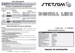
TAS-2400
ORDERCODE D4193
Congratulations!
You have bought a great, innovative product from DAP Audio.
The DAP Audio TAS series bring excitement to any venue. Whether you want simple plug-&-play action or a
sophisticated show, this product provides the effect you need.
You can rely on DAP Audio, for more excellent audio products.
We design and manufacture professional audio equipment for the entertainment industry.
New products are being launched regularly. We work hard to keep you, our customer, satisfied.
You can get some of the best quality, best priced products on the market from DAP Audio.
So next time, turn to DAP Audio for more great audio equipment.
Always get the best -- with DAP Audio !
Thank you!
DAP Audio
DAP Audio TAS-1100, TAS-1500, TAS-1900, TAS-2400, TAS4000 Product Guide
Warning.................................................................................................................................................................
Safety-instructions............................................................................................................................................
Operating Determinations..............................................................................................................................
2
2
3
Description.............................................................................................................................................................
Features.............................................................................................................................................................
Overview Front panel......................................................................................................................................
Overview Back panel......................................................................................................................................
4
5
5
6
Operation...............................................................................................................................................................
7
Mode selection......................................................................................................................................................
7
Connection Cables...............................................................................................................................................
10
Maintenance..........................................................................................................................................................
11
Troubleshooting.....................................................................................................................................................
11
Product Specifications..........................................................................................................................................
12
Appendix 1: TAS block diagram.........................................................................................................................
13
Appendix 2: Wire Gauge Charts..........................................................................................................................
14
1
WARNING
CAUTION!
Keep this system away from rain and moisture!
FOR YOUR OWN SAFETY, PLEASE READ THIS USER MANUAL CAREFULLY
BEFORE YOUR INITIAL START-UP!
SAFETY INSTRUCTIONS
Every person involved with the installation, operation and maintenance of this system have to:
be qualified
follow the instructions of this manual
CAUTION! Be careful with your operations.
With a dangerous voltage you can suffer
a dangerous electric shock when touching the wires!
Before you initial start-up, please make sure that there is no damage caused by transportation. Should there
be any, consult your dealer and do not use the system.
To maintain perfect condition and to ensure a safe operation, it is absolutely necessary for the user to follow
the safety instructions and warning notes written in this manual.
Please consider that damages caused by manual modifications to the system are not subject to warranty.
This system contains no user-serviceable parts. Refer servicing to qualified technicians only.
IMPORTANT:
The manufacturer will not accept liability for any resulting damages caused by the nonobservance of this manual or any unauthorized modification to the system.
Never let the power-cord come into contact with other cables! Handle the power-cord and all
connections with the mains with particular caution!
Never remove warning or informative labels from the unit.
Never use anything to cover the ground contact.
Do not insert objects into air vents.
Do not connect this system to a dimmerpack.
Do not switch the system on and off in short intervals, as this would reduce the system’s life.
Do not open the device and do not modify the device.
Do not open this device. Risk: hazardous radiation exposure.
Only use system indoor, avoid contact with water or other liquids.
Avoid flames and do not put close to flammable liquids or gases.
Always disconnect power from the mains, when system is not used. Only handle the power-cord by
the plug. Never pull out the plug by tugging the power-cord.
Make sure you don’t use the wrong kind of cables or defective cables.
Make sure that the signals into the mixer are balanced, otherwise hum could be created.
Make sure you use DI boxes to balance unbalanced signals; All incoming signals should be clear.
Make sure that the available voltage is not higher than stated on the rear panel.
2
Make sure that the power-cord is never crimped or damaged. Check the system and the powercord from time to time.
Make sure that the amplifier is turned down, before turning the power on or off. So you can avoid
supersonic frequencies, which could damage your speakers.
Don't put your equipment next to TV, radio, etc., because of interference or distortion.
If you connect other parts of the system, be careful of ground loops.
The best way to avoid ground loops is connecting the electrical system ground to one central point
("star" system). In this case the mixer can act as a central point.
Before changing the ground, always turn off your amplifier.
Please read this manual carefully and keep it for future reference. Remember that the amplifier has a
better value on the market, if you save the carton and all packing materials.
Always operate the unit with the AC ground wire connected to the electrical system ground.
Connecting amplifier outputs to oscilloscopes or other test equipment, while the amplifier is in
bridged mode, may damage both the amplifier and test equipment.
Do not drive the inputs with a signal level bigger, than required to drive the equipment to full output.
In system setup, the amplifier's output power must be 50%-100% more than the loaded loudspeakers
rated power.
Please turn off the power switch, when changing the power cord or signal cable, or select the input
mode switch.
In typical use, please set the volume at 0dB position.
Sometimes, when you want to send one signal to more than one amplifier, you should use a signal
distributor.
If your Dap Audio device fails to work properly, discontinue use immediately. Pack the unit securely
(preferably in the original packing material), and return it to your Dap Audio dealer for service.
Allow time to cool down, before cleaning or servicing.
For replacement use fuses of same type and rating only.
Prevent distortion! Make sure that all components connected to the device have sufficient power
ratings. Otherwise distortion will be generated because the components are operated at their limits.
Avoid ground loops! Always be sure to connect the power amps and the mixing console to the same
electrical circuit to ensure the same phase!
If system is dropped or struck, disconnect mains power supply immediately. Have a qualified
engineer inspect for safety before operating.
If the system has been exposed to drastic temperature fluctuation (e.g. after transportation), do not
switch it on immediately. The arising condensation water might damage your system. Leave the
system switched off until it has reached room temperature.
This device falls under protection class I. Therefore it is essential to connect the yellow/green
conductor to earth.
Repairs, servicing and electric connection must be carried out by a qualified technician.
WARRANTY: Till one year after date of purchase.
OPERATING DETERMINATIONS
If this system is operated in any other way, than the one described in this manual, the product may suffer
damages and the warranty becomes void.
Any other operation may lead to dangers like short-circuit, burns, electric shock, etc.
You endanger your own safety and the safety of others!
Improper installation can cause serious damage to people and property !
3
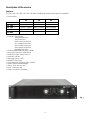
Description of the device
Features
The TAS-1100, TAS-1500, TAS-1900, TAS-2400, TAS4000 are professional high-end amplifiers :
• Power rating
TAS-1100
2Ω
Not allowed
4Ω
RMS 2 X 550W
8Ω
RMS 2 X 300W
TAS-1500
RMS 2 X 1200W
RMS 2 X 750W
RMS 2 X 450W
TAS-1900
RMS 2 X 1500W
RMS 2 X 950W
RMS 2 X 580W
TAS-2400
RMS 2 X 1800W
RMS 2 X 1200W
RMS 2 X 700W
TAS-4000
Not allowed
RMS 2 X 2000W
RMS 2 X 1200W
• Features: Clip limiting
Thermal protection
VHF protection
Short circuit protection
DC voltage protection
Zero current protection
Zero impact protection
Highpass filter: 30Hz
• Crosstalk 20Hz~20KHz, 8 Ohm: >60dB
• Frequency response: 20Hz~20KHz
• Sensitivity 8 Ohm stereo 1KHz: 1V
• S/N Ratio: >80 dB
• Damping Factor: >300
• Slewrate: >20V/uSec
• Total Harmonic distortion (THD): <0,05%
• Mode: Stereo/Parallel/Bridge
• Airflow: From front to rear
• Input connector: XLR
• Output connector: Speakon
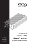
Fig. 1
4
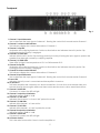
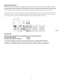
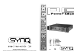
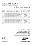
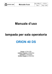
Frontpanel
Fig. 2
1. Channel 1 Input Attenuator.
Use to attenuate the input signal of channel 1. Pressing the control for 2 seconds mutes Channel 1.
2. Channel 1 volume scale indicator.
This indicator displays the volume attenuation of Channel 1.
3. Channel 1 clip LED.
Illuminates at the clipping threshold, Continuous illumination also indicates that ACL (Active Clip
Limiting) protection circuitry is engaged.
4. Channel 1/2 Limit LEDs.
Indicate that the ACL (Active Clip Limiting) protection circuitry is limiting the input signal to protect the
speakers from damage caused by a clipping amplifier.
5. Channel 1/2 TEMP LEDs.
These LEDs will light if the temperature of CH1 or CH2 exceeds 95 oC.
6. Channel 2 clip LED.
Illuminates at the clipping threshold, Continuous illumination also indicates that ACL (Active Clip
Limiting) protection circuitry is engaged,
7. Channel 2 volume scale indicator.
This indicator displays the volume attenuation of Channel 2.
8. Channel 2 Input Attenuator.
Use to attenuate the input signal of channel 2. Pressing the control for 2 seconds mutes Channel 2.
9. Power LED.
Indicates that AC power is connected and the amplifier is turned on.
10. Air entrance.
TAS Series amplifiers are cooled by two, rear-mounted fans, Cool air flows over the heat sinks and
exhausts through the rear grills, Make sure these outlets remain clear to allow unrestricted air flow.
11. Channel 1 Mute LED.
If channel 1 is muted, the LED will light.
12. Channel 1 output level indicator.
Indication range: -22dB to +6dB.
13. Channel 1/2 VHF LEDs.
Indicates that channel 1 or 2 are in VHF protection mode.
14. Channel 1/2 ON LEDs.
Indicate that channel 1 or 2 are active.
15. Channel 1/2 DC LEDs.
Indicate that channel 1 or 2 are in protection mode.
16. Channel 2 output level indicator.
Indication range: -22dB to +6dB.
17. Channel 1 Mute LED.
If channel 2 is muted, the LED will light.
18. AC Power Switch.
This is the main Power switch. Press to turn the amplifier on.
5
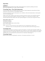
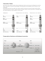
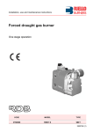
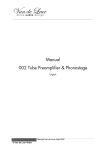
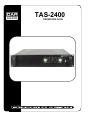
Backpanel
Fig. 3
19. Power Fuse.
Replace the fuse only by a fuse of the same type.
20. Mode Selection Switch.
This recessed, three-position switch configures the amplifier for Stereo, Parallel or Bridged Mono Mode
operation. Amplifiers are factory configured for Stereo Mode. See the section on Mode Selection for
more information.
21. Bridge Mode LED.
Indicates that the amplifier is working in bridge mode.
22. Input Sensitivity Selector.
This selector allows you, to choose the input sensitivity: 0,775V, 1,0V or 1,4V.
23. Air cooling windows
Make sure these outlets remain clear to allow unrestricted air flow.
24. Mains Cord
Connect to the mains.
25. Output terminal Connectors.
Using speaker cables, make connections to both the channel A and channel B connectors for Stereo or
Parallel mode, use the red terminals only for Bridged mono mode.
26. Output Speakon Connectors.
Use either the speakon connectors or the terminals. Using the speakon connectors, make connections
to both the channel A and channel B connectors for Stereo or Parallel mode, use only the channel A
connector for Bridged mono mode. Using the terminals, make connections to both the channel A and
channel B terminals for Stereo or Parallel mode, In bridged mono mode use only the red terminals. For
more information see page 8 and 9.
27. Grounding Switch.
To eliminate groundloops, put the selector in "OFF" position.
28. 30Hz High pass filter select.
This switch is used to cut the low frequencies under 30Hz.
29. Balanced XLR Input Connectors.
These connectors accept input signals on XLR input plugs, See the section on connecting cables on
page 10/11for information on polarity, Connectors for each channel are in parallel, The unused
connectors may be used for linking to other amplifiers.
30. Balanced Link Out connectors.
Used to Link the input signals to other amplifiers.
6
Operation
Installation
Remove all packing materials from the DSA. Check that all foam and plastic padding is removed.
Secure the equipment into a 19" rack. Connect all cables.
Connecting Power / Circuit Size Requirements.
The actual current draw, the amplifier demands from the AC mains, depends on many factors (its load,
output level or the crest factor of its program material).
The power requirement is rated under typical music conditions, with both channels driven so those peaks
are just at the clipping point.
Make sure the mains voltage is correct and is the same as printed on the rear of the amplifier. Damage
caused by connecting the amplifier to improper AC voltage is not covered by any warranty. Unless
otherwise specified when ordered. DAP audio amplifiers shipped to customers are configured as follows:
North America 120VAC/60Hz
Europe 230VAC/50Hz
Asia 220VAC /50Hz/60Hz
Australia 240VAC/50Hz
South America 120VAC/60Hz or 220VAC/50Hz
Japan 1OOVAC/50Hz
NOTE: Always turn off and disconnect the amplifier from mains voltage before making audio
connections. Also, as an extra precaution, have the attenuators turned down during power-up.
Connecting Inputs.
Use the XLR input connectors on the rear to supply audio signals to your DAP Audio TAS Series amplifier. The
connectors accept balanced and unbalanced audio connections. (The TAS Series amplifiers are configured
standard with "Pin 2 hot" on XLR inputs. The Link connector can be used to loop the audio Input to another
amplifier Input. For more Information, see the section on Connection cables page 10.
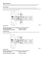
Connecting Outputs.
Speakers are connected using Speakon connectors. For examples see figures 4, 5 and 6.
7
Mode Selection
The three-position, recessed Mode Select switch (located on the rear panel) configures the amplifier for
either Stereo. Parallel or Bridged Mono Mode. Amplifiers are factory-configured for Stereo Mode.
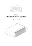
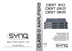
Stereo Mode
In Stereo Mode, both channels operate independently, with their input attenuators controlling their
respective levels. Signal at Channel A's input produces output at Channel A's output while signal at Channel
B's input produces output at Channel B's output.
Fig. 4
Important !!!
Absolute minimum nominal load Impedance for stereo operation Is:
TAS1100 and TAS4000:
4 Ohm per channel.
TAS1500, TAS1900 and TAS2400:
2 Ohm per channel.
Parallel Mode
When set to Parallel Mode, a signal applied to Channel A's input will be amplified and appear at outputs
of both Channels A&B.
Fig. 5
Important !!!
Absolute minimum nominal load Impedance for parallel operation Is:
TAS1100 and TAS4000:
4 Ohm per channel.
TAS1500, TAS1900 and TAS2400:
2 Ohm per channel.
8
Bridged Mono Mode
Bridged Mono Mode straps both amplifier channels together to make a very powerful, single-channel
monaural amplifier. One channel "pushes" and the other "pulls" equally, doubling the power over that of
channel alone. Signal is applied to the Channel A input only. Both attenuators are used to control signal
level; in addition, both must be adjusted to the same setting. Only channel A input may be used.
Use extreme caution when operating the amplifier In Bridged Mono Mode. Never ground either side of
the speaker cable when the amplifier Is in Bridged Mono Mode; both sides are "hot. "If an output patch
panel is used, all connections must be Isolated from each other and from the panel.
Fig. 6
Important!!!
Absolute minimum nominal load Impedance for bridge operation Is:
TAS1100 and TAS4000:
8 Ohm.
TAS1500, TAS1900 and TAS2400:
4 Ohm.
Connecting amplifier outputs to oscilloscopes or other test equipment while the
amplifier is in bridged mode may damage both the amplifier and test equipment!
9
Connection Cables
Take care of the connector cables, always holding them by the connectors and avoiding knots and twists
when coiling them: This gives the advantage of increasing their life and reliability, which is always to your
advantage.
Periodically check that your cables are in good condition, that they are correctly wired and that all their
contacts are in good condition: a great number of problems (faulty contacts, ground hum, discharges, etc.)
are caused entirely by using unsuitable or faulty cables.
Headphones
Unbalanced mono 1/4” jack plug
Compensation of interference with balanced connections
10
Balanced mono 1/4” jack plug
Maintenance
The DAP Audio TAS requires almost no maintenance. However, you should keep the unit clean. Disconnect
the mains power supply, and then wipe the cover with a damp cloth. Do not immerse in liquid. Do not use
alcohol or solvents.
Keep connections clean. Disconnect electric power, and then wipe the DMX and audio connections with a
damp cloth. Make sure connections are thoroughly dry before linking equipment or supplying electric
power.
Replacing a Fuse
Power surges, short-circuit or inappropriate electrical power supply may cause a fuse to burn out. If the fuse
burns out, the product will not function whatsoever. If this happens, follow the directions below to do so.
1. Unplug the unit from electric power source.
2. Insert a flat-head screwdriver into a slot in the fuse cover. Gently pry up the fuse cover. The fuse will
come out.
3. Remove the broken fuse. If brown or unclear, it is burned out.
4. Insert the replacement fuse into the holder where the old fuse was. Reinsert the fuse cover.
Be sure to use a fuse of the same type and specification. See the product specification label for details.
Troubleshooting
DAP Audio TAS-series Amplifiers.
This troubleshooting guide is meant to help solve simple problems. If a problem occurs, carry out the steps
below in sequence until a solution is found. Once the unit operates properly, do not carry out following steps.
1. If the device does not operate properly, unplug the device.
2. Check the fuse, power from the wall, all cables, etc.
3. If all of the above appears to be O.K., plug the unit in again.
4. If you are unable to determine the cause of the problem, do not open the amplifier, as this may damage
the unit and the warranty will become void.
5. Return the amplifier to your Dap Audio dealer.
11
Product Specifications
Power
TAS-1100
TAS-1500
TAS-1900
TAS-2400
TAS-4000
Stereo, 2 ohms (per ch.)
-
1200Wrms
1500Wrms
1800Wrms
-
Stereo, 4 ohms (per ch.)
550Wrms
750Wrms
950Wrms
1200Wrms
2000Wrms
Stereo, 8 oms (per ch.)
300Wrms
450Wrms
580Wrms
700Wrms
1200Wrms
Bridge mono, 8 ohms
1100Wrms
1500Wrms
1900Wrms
2400Wrms
4000Wrms
Performance
Frequency Response
THD + N
Slew rate
Damping factor
S/N Ratio
20Hz - 20kHz
<0,05
<0,05
<0,05
<0,05
<0,05
20V/μs
20V/μs
20V/μs
20V/μs
20V/μs
>300
>300
>300
>300
>300
>80dB
>80dB
>80dB
>80dB
>80dB
41,2dB
42dB
Sensitivity
Voltage gain
0,775mV/ 1,0mV/ 1,4mV
36,6dB
39dB
class AB
2 steps class H
Input impedance
Output circuit class
40dB
Balanced 20k/ unbalanced 10k
Hi-pass filter
3 steps class H
3 steps class H
17,15Kg
17,2Kg
30Hz
Power supply
Weight
3 steps class H
230V/ 50-60Hz
16,9Kg
17Kg
17,1Kg
Design and product specifications are subject to change without prior notice.
Website: www.Highlite.nl
Email: [email protected]
12
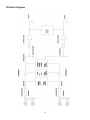
TAS Block Diagram
13
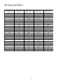
Wire Gauge Chart (Metric)
Stranded Cable
Wire Gauge
Power Loss %
Power Loss %
Power Loss %
Length (m)
2
(mm2)
(8 ohm load)
2,9
1,74
1,16
0,58
0,35
0,22
4,3
2,9
1,45
0,87
0,55
0,37
8,24
5,6
2,9
1,74
1,09
0,73
15,5
8,2
5,1
3,2
2,2
1,31
(4 ohm load)
5,6
3,4
2,3
1,16
0,7
0,44
8,2
5,6
2,9
1,74
1,09
0,73
15,5
10,8
5,6
2,9
1,74
1,09
0,73
15,5
9,8
6,3
4,3
2,6
(2 ohm load)
10,8
6,7
4,5
2,3
1,39
0,87
15,5
10,8
5,6
3,4
2,2
1,45
28
19,9
10,8
6,7
4,3
2,9
45
28
18,2
12
8,2
5,1
5
10
30
0,3
0,5
0,75
1,5
2,5
4
0,5
0,75
1,5
2,5
4
6
0,5
0,75
1,5
2,5
4
6
0,75
1,5
2,5
4
6
10
14
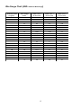
Wire Gauge Chart (AWG: American Wire Gauge)
Stranded Cable
Length(ft)
5
10
40
80
Wire Gauge
Power Loss %
Power Loss %
Power Loss %
(AWG)
18
16
14
12
10
18
16
14
12
10
18
16
14
12
10
8
18
16
14
12
10
8
(8 ohm load)
0.81
0.51
0.32
0.2
0.128
1.61
1.02
0.64
0.4
0.25
6.2
4
2.5
1.6
1.01
0.6
11.9
7.7
5
3.2
2
1.2
(4 ohm load)
1.61
1.02
0.64
0.4
0.25
3.2
2
1.28
0.8
0.51
11.9
7.7
5
3.2
2
1.2
22
14.6
9.6
6.2
4
2.4
(2 ohm load)
3.2
2
1.28
0.8
0.51
6.2
4
2.5
1.6
1.01
22
14.6
9.6
6.2
4
2.4
37
26
17.8
11.8
7.7
4.7
15
2007 Dap Audio.