1
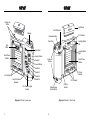
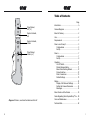
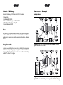
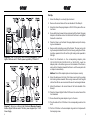
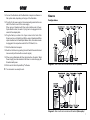
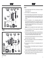
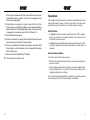
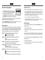
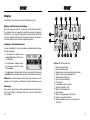
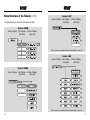
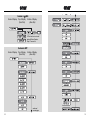
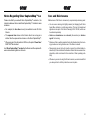
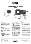
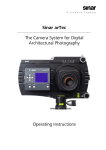
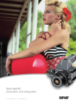
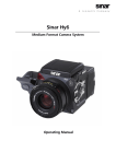
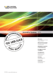
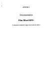
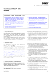
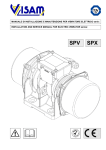
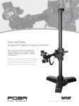
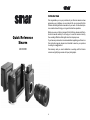
Introduction We congratulate you on your purchase of your Sinar m camera and we appreciate your confidence in our products. We are convinced that the Sinar m will add significant convenience to your work. Its robust and precise construction will bring you long and trouble-free operation. Quick Reference Sinar m 493.03.000 Before you use your Sinar m camera for the first time, please read this instruction manual carefully. It will help you to use the camera correctly, thus avoiding difficulties that might arise from improper use. If you have any comments or recommendations regarding your Sinar m or this instruction manual, please do not hesitate to send us your opinions in writing to [email protected]. We sincerely wish you much satisfaction in working with the Sinar m camera and gratifying success with your photographs. A Snap Lock Slider Light Gate On/Off Switch Display El. Contacts Release Button Front Dial Locking Slider, left Type Plate Rear Dial Focal Plane Shutter Locking Slider, right Upper Wheel Switch 1 Eylets for Straps Focal Plane Shutter Lower Wheel Switch 2 Switch 3 El. Contacts X Sync Socket Switch 4 Jack for Hand Release Switch 5 El. Contacts 12V Power Supply Socket Multipurpose Socket (AUX) Diagram 1: Sinar m, rear view C M Sync Socket Diagram 2: Sinar m, front view D Table of Contents Page Tripod Socket, left (3/8 ″) Introduction .................................................... A System Contacts, left Extent of Delivery ........................................... 2 System Contacts, bottom Requirements ................................................ 2 Tripod Socket, bottom (3/8 ″) Camera Diagrams ......................................... C Use ................................................................ 2 Sinar m on a Sinar p3 ..................................... 3 Configurations ......................................... 3 Set-Up ..................................................... 5 Sinar m ........................................................... 7 Configurations ......................................... 7 Set-Up ..................................................... 9 Operation ..................................................... 11 On / Off Switch ....................................... 11 Shutter Release Button ......................... 11 Menu Dials / Scrolling Wheels ................ 12 Rocker Switches .................................... 12 Flash Connections ................................. 13 Default Settings ..................................... 13 Display ......................................................... 14 Display of All Relevant Settings ............. 14 Setting the Camera Parameters ............ 14 Messages .............................................. 14 Menu Structure of the Sinar m ..................... 16 Notes Regarding Sinar CaptureShop™ 4.x.. 20 Diagram 3: Sinar m, view from the bottom and the left Care and Maintenance ................................ 21 Technical Data ............................................. 22 E 1 Extent of Delivery Sinar m on a Sinar p3 The extent of delivery of the Sinar m 493.03.000 includes: Configurations • • • • • Sinar m Body Light Gate 493.03.208 Two Shutter Protecting Covers 493.03.582 CD-ROM with Sinar CaptureShop™ Quick Reference 02.8302 Use The Sinar m is a versatile modular camera body. It can be used as a shutter for the Sinar p3 view camera as well as a stand-alone 35 mm or medium format camera (see also the example configurations, diagrams 4 to 11 ). Requirements Diagram 4: Sinar m on a Sinar p3 with Sinarback (firewire), Sinaron Digital CAB Lens and LC Shutter In order to work with the Sinar m you need, in addition to the accessories listed in the corresponding diagram, an Apple Power Macintosh G4 computer (or with higher performance) and the capture software Sinar CaptureShop™ version 4.1 or higher. Diagram 5: Sinar m on a Sinar p3 with Sinarback (fiber optics), Sinaron Digital CAB Lens and LC Shutter, power supplied by a 12 V Power Supply 2 3 Set-Up 1. Mount the Sinar p3 on a sturdy tripod or stand. 2. Remove the carrier frame of the rear standard of the Sinar p3. 3. Mount the Quick Clamping Adapter m 519.81.000 in place of the carrier frame. 4. Screw both tripod screws that are included with the Quick Clamping Adapter in the bottom and on the left side of the Sinar m and tighten them with a small coin. 5. Place the Sinar m on the Quick Clamping Adapter and pull its clamping lever backwards. Diagram 6: Sinar m on a Sinar p3 with Sinarback (fiber optics), Sinaron Digital CAB Lens and LC Shutter, power supplied by PCI Board 3 6. Remove both protecting covers of the Sinar m: The rear one by sliding the snap lock slider to the left, the front one by pulling the left locking slider upwards to the left and the right looking slider upwards to the right. 7. Mount the Sinarback on the corresponding adapter plate (551.63.235 / 551.64.235 / 551.65.235 or 552.35.232), insert the adapter plate in the bottom groove on the backside of the Sinar m, and push the Sinarback towards the Sinar m until the snap lock slider snaps in automatically. Notice: Check if the adapter plate is locked in place correctly. 8. Mount the bellows on the front of the Sinar m and lock it by pushing both locking sliders inwards. When using lenses with focal lengths shorter than 90 mm we recommend the use of a wide angle bellows. 9. Attach the bellows to the carrier frame of the front standard of the Sinar p3. 10. Place the Sinaron Digital CAB or CMV lens in the carrier frame of the front standard. 11. Screw the matching lens adapter ring on to the lens. Diagram 7: Sinar m on a Sinar p3 with Sinarback (M-series, firewire), Sinaron Digital CAB Lens and LC Shutter, power supplied by a 12 Volt Power Supply 4 12. Plug the cable of the LC Shutter in the corresponding socket on the lens. 13. Put the LC Shutter on the lens adapter ring and lock it in place with the clamping screw. 5 14. Connect the Sinarback with the Macintosh computer via firewire- or fiber optics cable, depending on the type of the Sinarback. 15. Plug the 12 volt power supply in the corresponding socket on the rear side of the Sinar m and on the mains supply. When using a Sinarback with fiber optics interface and a PowerOptics Master cable, the wide J14 plug has to be plugged into the socket of the adapter plate. Sinar m Configurations 16. Plug the flash sync cable in the X sync socket on the front of the Sinar m and on your flashlight unit. When using a Sinarback with fiber optics interface and a PowerOptics Master cable, this cable can also be plugged in the respective socket of the PCI Board 2, too. 17. Start the Macintosh computer. 18. Switch on the Sinar m by pushing the on/off switch forwards for about two seconds (confirmed with an acoustic signal). 19. When using a Sinarback with fiber optics interface, the option “Back Power Supply” must be activated in the Sinar m in order to supply the Sinarback with power. 20. Start now the Sinar CaptureShop™ software. ➤ Diagram 8: Sinar m with mirror module and Sinarback (firewire) Your camera is now ready to work. Diagram 9: Sinar m with mirror module and Sinarback (fiber optics) 6 7 Set-Up 1. Screw the Tripod Adapter 519.81.010 on to the Sinar m and tighten the screw with a coin. 2. Mount the Sinar m on a sturdy tripod or stand. 3. Remove both protecting covers of the Sinar m: The rear one by sliding the snap lock slider to the left, the front one by pulling the left locking slider upwards to the left and the right looking slider upwards to the right. 4. Mount the Sinarback on the corresponding adapter plate (551.63.235 / 551.64.235 / 551.65.235 or 552.35.232), insert the adapter plate in the bottom groove on the backside of the Sinar m, and push the Sinarback towards the Sinar m until the snap lock slider snaps in automatically. Notice: Check if the adapter plate is locked in position correctly. Diagram 10: Sinar m with mirror module and Sinarback (M-series, firewire) 5. Remove the Light Gate of the Sinar m (except when a Hasselblad Lens Module 493.64.012 is used). 6. Mount the mirror module or the lens module on the front of the Sinar m and lock it by pushing both locking sliders inwards. Check if the mirror module or the lens module is locked in position correctly. 7. Mount the view finder and the desired lens in the mirror module respectively the lens in the lens module. 8a. When using a Hasselblad Lens Module, screw the matching lens adapter ring on the lens bayonet. 8b. Plug the cable of the LC Shutter in the corresponding socket on the lens module. 8c. Put the LC Shutter on the lens adapter ring and lock it in place with the clamping screw. 9. Connect the Sinarback with the Macintosh computer either via the firewire or fiber optics cable depending on the type of the Sinarback. Diagram 11: Sinar m with Hasselblad lens module, Sinarback (firewire) and LC Shutter 8 10. Plug the 12 Volt power supply in the corresponding socket on the rear side of the Sinar m and on the mains supply. 9 When using a Sinarback with fiber optics interface and a PowerOptics Master cable, the wide J14 plug has to be plugged into the socket of the adapter plate. 11. Plug the flash sync cable in the X sync socket on the front of the Sinar m and on your flashlight unit. When using a Sinarback with fiber optics interface and a PowerOptics Master cable, this cable can also be plugged in the respective socket of the PCI Board 2, too. 12. Start the Macintosh computer. 13. Switch on the Sinar m by pushing the on/off switch forwards for about two seconds (confirmed with an acoustic signal). 14. When using a Sinarback with fiber optics interface, the option “Back Power Supply” must be activated in order to supply the Sinarback with electrical power. Operation The operation of the camera and the selection of individual functions are mainly performed by means of the two menu dials and the five rocker switches (also see the illustrations on the fold-out pages C and D). On /Off Switch • To activate the Sinar m, press this switch forward to “ON” for approximately two seconds. A successful activation of the camera is confirmed with an acoustic signal. • To switch the camera off, press the switch towards the back to “OFF”. An acoustic signal will resound (when the feature “Acoustic Signal” is activated). 15. Start now the Sinar CaptureShop™ software. Shutter Release Button ➤ The shutter release button has two steps: Your camera is now ready to work. • When the release button is pressed all the way down (second step) an exposure is made. • By touching the release button (first step), you exit the respective camera menu (Switches 2, 3 or 4), which you may have activated, and the displayed setting will be confirmed. Every time the shutter release button is actuated, an acoustic signal will resound (when the function “Acoustic Signal” is activated). 10 11 Menu Dials / Scrolling Wheels • The Front Dial permits the selection of functions listed in the upper line in the display, and the setting of the working aperture. • The Rear Dial allows the selection of functions listed in the lower line of the display, and the setting of the exposure time. Please check the tables on pages 16 to 19 to see all the functions that are available and how the menu is structured. Flash Connections The Sinar m is equipped with two synchro flash connectors: “X” and “M”. • The “X” contact triggers the flash either at the instant when the shutter window has reached its largest opening (setting “Early Flash”), or immediately before the shutter begins to close again (setting “Late Flash”). This is the contact that is normally used. The “X” contact can also be switched off (setting “Off”). • The “M” contact triggers the flash at the moment when the shutter begins to open. The “M” contact cannot be switched off. The two Scrolling Wheels are foreseen for future tasks. In the current version of the Sinar m program they have no function. Default Settings Rocker Switches In order to reactivate the default setting of the Camera Settings (menus), proceed as follows: The rocker switches can be activated in three positions: switch pressed to the left, switch pressed to the right and switch pressed at the center position. The Switches 2, 3 and 4 lead to a different operation level. By touching the release button you will return to the capturing level. 1. First, switch the camera off. 2. While pressing the shutter release button, switch on the camera at the same time. Switch 1: “AE-L” locks the automatic exposure measurement; “AF-L” locks the autofocus function; “ ” locks both functions together. In the diagrams in the chapter Menu Structure of the Sinar m the parameters that correspond to the default factory settings are highlighted gray. Switch 2: “PRGM” opens the menu for the program modes of the Sinar m; “MODE” opens the menu of the exposure modes. To restore the default setting of the Display (brightness and contrast), proceed as follows: ooo Switch 3: “EXP” opens the menu for the exposure measurement; “WB” opens the menu for the white balance. 1. First, switch the camera off. 2. Hold down Switches 1 and 5 at the same time (at their centers) and turn the camera on again. Switch 4: “ /ISO” opens the menu for selecting a flash setting and for the exposure sensitivity; “OPT” opens the menu for all the possible options. Switch 5: “Mirror” enables to lock the mirror up before the exposure is made; “ ” enables to stop the iris diaphragm down to the working aperture; “LIVE” starts/ends the live image generated by the Sinarback. 12 13 Display 1 The display on the Sinar m camera has the following modes: 2 3 4 5 Display of All the Relevant Settings When the camera is ready for an exposure, all the settings relevant to that exposure that are supported by attached modules are displayed. Illustration no. 12 on page 15 shows which camera functions will be indicated in a particular location within the display. The symbols change in conformity with the status of the corresponding function. 6 8 7 Setting the Camera Parameters As soon as Switches 2, 3 and 4 are actuated, a display divided into three sections will appear: • In the center, the respective overall menu title of the operation level is displayed. • The parameters indicated above the title can be varied by turning the Front Dial. • The parameters indicated below the title can be varied by turning the Rear Dial (also see chapter Menu Structure of the Sinar m on page 16). Notice: Some of the settings exclude each other mutually or are depending one from another. Accordingly the options available may vary. Messages Error reports, warnings and notes regarding unusual operating situations, such as “Busy” or “Operation locked” etc., are also communicated by this display. 14 9 10 11 12 13 14 Diagram 12: Display overview 1. 2. 3. 4. 5. 6. 7. 8. 9. 10. 11. 12. 13. 14. Selected program mode Selected capture mode Stopped down to working aperture/focus mode Aperture control not coupled with lens Selected working aperture Type of exposure metering Flash mode Light balance / Exposure value Selected sensitivity in ISO Status of the shutter/mirror White balance State of charge/warning of the battery Exposure correction activated Selected exposure time in 1/x seconds resp. in seconds x" 15 Menu Structure of the Sinar m (V 1.0) Center of Display The highlighted boxes corresponds to the default condition. Switch 3: EXP Top of Display Bottom of Display (Front Dial) (Rear Dial) Switch 2: PRGM Center of Display Top of Display Bottom of Display (Front Dial) (Rear Dial) * This function is not available with Sinar CaptureShop™ version 4.x. Center of Display Switch 3: WB Top of Display Bottom of Display (Front Dial) (Rear Dial) Switch 2: MODE Center of Display Top of Display Bottom of Display (Front Dial) (Rear Dial) * This function is not available with Sinar CaptureShop™ version 4.x. 16 17 Switch 4: /ISO Center of Display Top of Display Bottom of Display (Front Dial) (Rear Dial) This function is not avail*able with Sinar CaptureShop™ version 4.x. Center of Display Switch 4: OPT Top of Display Bottom of Display (Front Dial) (Rear Dial) continued on next page 18 19 Notes Regarding Sinar CaptureShop™ 4.x Care and Maintenance Please note that if you work with Sinar CaptureShop™ version 4.x, the interaction between Sinar m and Sinar CaptureShop™ is limited in some situations. Maintenance of the Sinar m camera only requires simple cleaning work: • For example, the live video can only be switched on and off at the Sinar m. • You can use a cleaning cloth lightly soaked (not dripping!) with Sinar Agent Blue, ethanol or a mild soap solution. The two first mentioned agents are also part of the Sinar Cleaning Kit 551.33.090, which can be ordered separately. • The exposure time chosen on the Sinar m has to be as long as or shorter than the exposure time chosen on the Sinar CaptureShop™. • Under no circumstances use solvents (like acetone) or abrasive agents for cleaning. • When using an LC shutter and/or a CMV lens, the option “Power Save” MUST NOT be activated. • Make sure that no wetting reaches the shutter blades during the cleaning procedure or during outdoor use of the Sinar m camera. As of Sinar CaptureShop™ version 5.x the Sinar m and the capture software communicate together on all levels. • Take special care not to touch, handle or press the shutter blades inadvertently.That can deform the blades or hinder their movement characteristics, which could result in the reduction of their operating reliability. • Whenever you are not using the Sinar m camera, we recommend that you always store it with the protective covers in place. 20 21 Technical Data Dimensions: 180 × 140 × 67 mm (approx. 7 × 51/2 × 2 5/8 ″) Weight: 0.8 kg (approx. 28 oz) Lenses: Sinaron Digital CAB, Sinaron Digital CMV, Hasselblad V-System, Nikon (further adaptations are in preparation) Shutter Type: Electronically controlled, vertically moving focal plane shutter Shutter Size: 56 × 42 mm (approx. 21/4 × 15/8 ″) Shutter Durability: Typical 50,000 release cycles Exposure Times: 1/2000 Flash Sync Time: 1/100 Tripod Socket: 2× 3/8 ″ (1× bottom, 1× left) Power Supply: 12 Volt DC second to 68 minutes (depending on the configuration) second Operating Temperature: +5° to +45°C (+41°F to +113° F) Storage Temperature: -10° to +60°C (+14°F to +140° F) Relative Humidity: 5% to 80%, not condensing SINAR AG CH-8245 Feuerthalen/Switzerland Telephone + 41/ 52 647 07 07 Fax + 41/ 52 647 06 06 E-mail [email protected] Website www.sinarcameras.com 22 V2/040130 Printed in Switzerland Technical modifications reserved 927.04/02.77.000.1 e – 02.8302 2003 SINAR AG, Switzerland