1
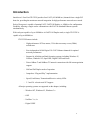
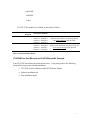
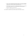
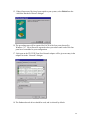
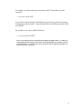
ITIpci 5232E Four Port Ethernet and Fast Ethernet PCI Host Adapter Installation and User’s Guide Order Number 9806-5232M IntraServer Technology, Inc., Copyright 1998 quad_enet.doc 1 Copyright 1998 First Printing, June 1998 Copyright Copyright 1998 IntraServer Technology, Inc. No part of this manual may be reproduced in any form, mechanical or electronic without the prior written consent of IntraServer Technology, Inc. Seven October Hill Road, Holliston, MA 01746. Trademarks The following are trademarks of IntraServer Technology, Inc. ITIpci, ClusterReady, and the IntraServer logo. All other trademarks are the property of their respective holders and acknowledged. Information Subject to Change The information in this manual is subject to change without notice and should not be construed as a commitment by IntraServer Technology, Inc. Reasonable efforts have been made to assure the accuracy of this manual, IntraServer Technology, Inc. assumes no liability resulting from errors or omissions in this manual or from the use of the information in the manual. IntraServer retains the right to make changes to this manual and the products without prior written notification. Readers Comment Card The Reader’s Comments form at the end of this document requests your critical evaluation to assist in preparing future documents IntraServer Technical Support Technical support and information is available by calling IntraServer Technology, Inc. direct at 508-429-0425 or your product reseller. IntraServer Technology, Inc.’s World Wide Web site is at http://www.intraserver.com/. Product information, support FAQ’s, and device drivers are available at the Company’s web site. 2 Class B Device Certification Statements Federal Communications Commission Radio Frequency Interference Statement This equipment has been tested and found to comply with the limits for a Class B digital device, pursuant to Part 15 of the FCC rules. These limits are designed to provide reasonable protection against a harmful interference in residential installations. This equipment generates, uses, and can radiate radio frequency energy, and if not installed and used in accordance with the instruction manual, may cause harmful interference to radio communications. However there is no guarantee that interference will not occur in a particular installation. If this equipment does cause interference to radio or television equipment reception, which can be determined by turning the equipment off and on, the user is encouraged to try to correct the interference by one or more of the following measures: Reorient or relocate the receiving antenna Move the equipment away from the receiver Plug the equipment into an outlet on a circuit different from that to which the receiver is powered If necessary, the user should consult the dealer or an experienced radio/television technician for additional suggestions CAUTION: Only equipment certified to comply with Class B (computer input/output devices, terminals, printers, etc.) should be attached to this equipment, and must have shielded interface cables. This device complies with part 15 of the FCC rules. Operation is subject to the following two conditions: (1) this device may not cause harmful interference and (2) this device must accept any interference received , including interference that may cause undesired operation. Each host adapter is equipped with an FCC compliance label which shows the FCC Identification number. The full text of the label is in the preceding paragraph. Finally, any changes or modifications to the equipment by the user not expressly approved by the grantee manufacturer could void the user’s authority to operate such equipment. Canadian Compliance Statement This Class B digital apparatus meets all requirements of the Canadian Interference-Causing Equipment Regulations. Cet appareil numerique de la classe B respecte toutes les exigences du Reglement sur le material brouiller du Canada European Compliance Statement WARNING: This is a Class B product. In domestic environments this product may cause radio interference in which case the user may be required to take adequate measures. Please write to IntraServer Technology, Inc, Seven October Hill Road, Holliston, MA 01746 with regards to any questions on this product. 3 Introduction........................................................................................................................ 6 ITI-5232E Four Port Ethernet and FAST Ethernet Kit Contents ........................................ 7 Connectors and Indicator LEDs ............................................................................................... 8 Hardware Installation........................................................................................................ 9 System Requirements ................................................................................................................ 9 Installing the adapter................................................................................................................. 9 Network Device Driver Installation Instructions............................................................ 11 Windows NT ............................................................................................................................. 11 Contents of the driver kit .......................................................................................................................11 Installing the ITI-5232E (DC21X4 Driver) on Windows NT: ..........................................................12 Windows 95 Installation for PCI systems.............................................................................. 18 NetWare .................................................................................................................................... 23 Linux.......................................................................................................................................... 25 For information regarding drivers, installation, and support for Linux please visit our World Wide Web site at http://intraserver.com/support/faq.html......................................................... 25 Digital UNIX ............................................................................................................................. 26 Digital OpenVMS..................................................................................................................... 27 Appendix A ....................................................................................................................... 28 Digital’s SRM Console Settings .............................................................................................. 28 Displaying and Setting Ethernet Port Characteristics ............................................................................28 Appendix B ....................................................................................................................... 30 Connector Pin Assignments .................................................................................................... 30 Cabling Requirements ............................................................................................................. 31 Appendix C: Troubleshooting....................................................................................... 32 Windows NT Version 4.0 and 3.51 ......................................................................................... 32 Error messages ......................................................................................................................................32 Driver initialization errors: ................................................................................................................33 Driver run time errors:.......................................................................................................................33 Windows 95............................................................................................................................... 34 Appendix D: Adapter Specifications ............................................................................. 36 ITI-5232E Four Port 10/100 Ethernet PCI adapter ............................................................. 36 4 Tables Table 1 ITI-5232E Adapter Models ________________________________________________________7 Table 2 Connections and Indicator LEDs ___________________________________________________8 Table 3 Contents of Software Distribution Floppy ___________________________________________11 Table 4 Digital UNIX and OpenVMS SRM Console Media Selection _____________________________28 Table 5 8-Pin MJ Connector Pin Assignments_______________________________________________30 Table 6 Adapter to Network Hub Wiring ___________________________________________________31 Table 7 Adapter to Adapter (point to point) Wiring ___________________________________________31 Table 8 DC21X4 NT driver error codes____________________________________________________33 Figures Figure 1 Connectors and Indicator LEDs ___________________________________________________8 Figure 2 8-Pin MJ Connector (Front) _____________________________________________________30 5 Introduction IntraServer’s Four Port ITI-5232E provides four FAST (10/100Mb/sec) channels from a single PCI host slot, providing the maximum network integration for high performance network server needs. Each of four ports is capable of running FAST, FAST Full Duplex, or 10Mb/sec for configuration flexibility, allowing a single card to communicate with FAST or Standard Ethernet systems simultaneously. With each port capable of up to 200Mb/sec in FAST Full Duplex mode, a single ITI-5232E is capable of up to 800Mb/sec. ITI-5232E features include: - High performance PCI bus master, 32-bit direct memory access (DMA) architecture - Four independent 10/100 Digital 21143-PC Ethernet channels for optimal network performance - Support for all Alpha and Intel Operating systems, including Windows 95, Netware, Windows NT, OpenVMS, Digital UNIX and Linux. - Direct 10Base-T and 100Base-TX network connection with full auto-negotiation support - Half and Full Duplex mode of operation - Jumperless “Plug and Play” implementation - Speed, Link Status, Transmit and Receive activity LEDs - 3.3 and 5.0 volt universal PCI support All major operating systems are supported on the adapter, including: - Windows NT, Windows 95, Windows 3.x - OS/2 - NetWare 3.x, 4.x - Digital UNIX 6 - OpenVMS - MS/DOS - Linux Two ITI-5232E models are available, as described in Table 1. Model ITI-5232E-N Interrupts Required 1 ITI-5232E-O/U 4 Interrupt Assignment Description Channel 0 – Interrupt A Channel 1 – Interrupt A Channel 2 – Interrupt A Channel 3 – Interrupt A Channel 0 – Interrupt A Channel 1 – Interrupt B Channel 2 – Interrupt C Channel 3 – Interrupt D Four Port Channel FAST Ethernet Adapter for Windows NT, Windows 95 operating systems that support sharing of PCI interrupts Four Port Channel FAST Ethernet Adapter for Digital UNIX, OpenVMS operating systems that do not support sharing of PCI interrupts Table 1 ITI-5232E Adapter Models ITI-5232E Four Port Ethernet and FAST Ethernet Kit Contents Your ITI-5232E kit includes the items shown below. Verify that you have the following items before you proceed with the installation: • ITI-5232E Four Port Ethernet and FAST Ethernet Adapter • Software installation kit • This installation guide 7 Connectors and Indicator LEDs The ITI-5232E provides four 8-pin Modular Jack (MJ) connectors for connection with your network. Each of these four ports supports either Twisted Pair Category 3 or 5 cable for 10Mb/s connections, or Category 5 cable for 100Mb/sec operation. Figure 1 shows the ITI-5232E Adapter connectors and indicator LEDs. 1 Port 0 2 Port 1 3 Port 2 4 Port 3 5 6 7 8 Port Port Port Port 0 1 2 3 Figure 1 Connectors and Indicator LEDs Table 2 describes the ITI-5232E Four Port Fast Ethernet Adapter connectors and indicator LEDs. Reference ❶ Component Channel 0 8-pin MJ Connector ❷ Channel 1 8-pin MJ Connector ❸ Channel 2 8-pin MJ Connector ❹ Channel 3 8-pin MJ Connector ❺ Channel 0 Indicator LEDs ❻ Channel 1 Indicator LEDs ❼ Channel 2 Indicator LEDs ❽ Channel 3 Indicator LEDs Description 10/100 Mb/s twisted-pair network connector for Channel 0 10/100 Mb/s twisted-pair network connector for Channel 1 10/100 Mb/s twisted-pair network connector for Channel 2 10/100 Mb/s twisted-pair network connector for Channel 3 100 Mb/s (Left LED) Activity (Center LED) Link (Right LED) 100 Mb/s (Left LED) Activity (Center LED) Link (Right LED) 100 Mb/s (Left LED) Activity (Center LED) Link (Right LED) 100 Mb/s (Left LED) Activity (Center LED) Link (Right LED) Table 2 Connections and Indicator LEDs 8 Hardware Installation This chapter describes how to install the ITI-5232E adapter in your PCI based bus master compatible computer, and how to connect it to your network. The ITI-5232E host adapter is Plug and Play on the host systems PCI bus, and no configuration of the adapter hardware is necessary. System Requirements Before you begin the installation procedure, you will need: • An available PCI bus master expansion slot • A system that is compatible with the PCI Specification, Version 2.1 • A floppy disk drive for loading the software drivers • UTP category 3,4 or 5 cable (type dependant on your network type) For multi-channel adapters such as the ITI-5232E it is required that your host system firmware or BIOS support PCI bridging. If your host does not support PCI bridging contact your system vendor for a BIOS upgrade. If your system can not be brought into compliance with the PCI bridge specification, then you will not be able to use multi-channel ITIpci host adapters. Installing the adapter The following procedure should be used to install the ITI-5332E adapter: 1. Turn OFF the power to the computer system, and to all peripherals directly connected to the system (monitor, printer, external SCSI enclosures, etc.) 2. Unplug the system from the AC power line 3. Use an anti-static strap or precautions to avoid static discharge to your computer system or the ITI-5232E adapter 4. Remove the access cover from your system (refer to the system’s documentation) 9 5. Locate a free PCI expansion slot (small white connector on the system’s motherboard) and remove the screw and metal bracket for the selected slot. Be certain not to install the adapter in an ISA or EISA slot, which are longer than the PCI slots 6. Install the adapter in the selected slot. The module should fit without forcing, and should line up with the I/O bulkhead. Be certain that the adapter is fully seated in the slot 7. Replace the retaining screw removed in step 5 8. Connect to your Ethernet HUB using uncrossed Twisted Pair cable. After installation, re-assemble the system enclosure, and proceed with Software installation. 10 Network Device Driver Installation Instructions Windows NT The ITI-5232E Four Port Ethernet and Fast Ethernet adapter uses the industry leading Fast Network Engine, Digital’s DC21143 PCI MAC. Digital’s DC21X4.SYS mini-port driver is used to support the four Ethernet channels on the card. Contents of the driver kit Your ITI-5232E kit includes a floppy disk, which contains the Windows NT and Windows 95 drivers. The floppy disk contains the following files and directories: Operating System A:\WINNT A:\WIN95 A:\ Architecture (NT only) \ALPHA File Name \ DC21X4.SYS The Alpha executable driver file for DC21143 Ethernet Chip \INTEL \ DC21X4.SYS The Intel executable driver file for DC21143 Ethernet Chip \ DC21X4.SYS The Intel executable driver file for DC21143 Ethernet Chip \NDIS.VXD \DISK1 \NETPCI.INF \OEMSETNT.INF \README.TXT NDIS Wrapper file Flag file for NT Win’95 Setup information file NT Setup information file Information released since the last publication of the documentation (if any) Information specific to this software release (if any) \RELEASE.NOT File Description Table 3 Contents of Software Distribution Floppy 11 Installing the ITI-5232E (DC21X4 Driver) on Windows NT: Follow the procedure below to install the NT driver on your Intel or Alpha based system. The choices you are given may vary slightly from these examples based on your machine’s current network configuration and options. See your system administrator for any additional information. Note: Digital’s Alpha systems use a dynamic link library file (DLL) called a hardware abstraction layer (HAL). This file can be found on your boot disk at the location \os\hal.dll. This is a system file and is hidden. You must use the “show system and hidden files” option under explorer to see this file. Certain Alpha systems will hang after installing multi-port Ethernet cards unless this file is updated to hal.dll dated on or after 26-MAY-1998. If you experience this hang, shut down the machine, and remove the ITI-5232E from your system. Contact Digital for an updated HAL, and installation instructions. 1. From the Windows NT START Menu, select the Control Panel icon. 2. From the Control Panel menu select the Network icon. 12 If a dialog box asks you "Do you want to install NT Networking?" select YES and continue. Place the Windows NT installation media the CD-ROM reader, and complete the Windows NT network installation. Consult Windows NT documentation if you are unfamiliar with this process. Follow the on-screen prompts until you are prompted for a Network Adapter Type. 3. From the “Network” dialog, select the Adapters tab, then select Add. 4. From the “Select Network Adapter” dialogue, select Have Disk… 13 5. Insert the ITI-5232E driver diskette in your floppy drive and select OK. 14 6. From the “Select OEM Option” dialogue, Select “IntraServer ITI5232E Four Port 10/100 Mbps Ethernet” adapter, and select OK. 7. A “Connection Type” dialog box will allow you to select the connection type appropriate for your network configuration. The default connection type is AutoSense, which should be correct for most network connections. 8. Should you need to change the media connection type, be certain to select the correct connection type for your network. If not, the adapter port will not be able to “link” to the network. 15 9. Upon completion, the selected adapter port(s) is (are) added to the Installed Adapter Cards list in the Network Setting box (the number prefixing the adapter is the adapter port number). 10. Select OK to complete the Network Setting initialization. Based on the protocols you are running, one, or more dialog boxes may appear. See your network administrator for appropriate settings for your network for each of the dialog boxes. A typical dialog (TCP/IP) shown for example. 16 11. Shutdown and reboot the system. 17 Windows 95 Installation for PCI systems The following step should be taken in order to use the IntraServer Technology, Inc. ITI5232E Four Port Fast Ethernet 10/100 adapter in a system running Windows 95: 1. Power the machine down, unplug the AC power line, and remove the access cover. 2. Install the ITI5232 into an unused PCI slot. Attach the network cable(s) from the card to your existing network device. 3. Replace the access cover of your machine. 4. Replace the AC power line, and boot Windows 95. 5. When Windows 95 detects the new hardware, a message: "New Hardware Found, PCI Ethernet Controller" will be displayed. 6. Put the Software Installation Floppy in your Floppy drive, then select Next >. 6. Windows ’95 will read the installation floppy, and will automatically find the ITI5232E Four Port Ethernet controller Select Finish. If you are the “Select Device” dialog box to select the ITI-5232 Four Port 10/100 Mbps Ethernet Adapter” from the list and select OK. 18 12. Windows ’95 may prompt you to insert the distribution media disk(s) to be installed at this time. 13. Some files will be copied from your distribution media disk(s) and some from the OEM distribution floppy disk. 14. If Windows prompts you for a file location of the distribution files, select the default location A:\ and select OK. 19 15. When all necessary files have been copied to your system, select Finish from the “Add New Hardware Wizard” dialogue. 16. The preceding steps will be repeated for EACH of the four ports detected by Windows ’95. You will need to repeat the above procedures until each of the four ports have been added to your configuration. 17. Each port on the ITI-5232E Four Port Network adapter will be given an entry in the adapter list in the “Network” dialogue. 18. The Enhanced mode driver should be used, and is selected by default. 20 19. The ITI-5232E is capable of full AutoSense, which should allow plug and play operation with your network. Should the need arise to specify the physical media, select the “Advanced” tab, then select Connection Type, and select the connection type that matches your network. 20. Select OK. Based on the network protocols running on your system, one or more dialogue boxes may appear. See your network administrator for the network settings for this machine. 21 21. When prompted, allow the machine to restart, to allow the new network settings to become active. 22 NetWare The Novell Netware driver, DC21x4 is used with both Netware 3.1x and Netware 4.x servers. Netware 3.x Server Driver 1. Prepare the hard drives of your server according to the instructions in your Netware 3.1x documentation. 2. While the server is down, insert the IntraServer Setup diskette into your server’s A drive. 3. Copy the contents of a:\netware\311 or a:\netware\312 to the disk from which you boot Netware 3.1x 4. Type SERVER at the DOS prompt press Enter to boot the Netware 3.1x Server. 5. Type LOAD INSTALL at the server console prompt and press Enter 6. Select System Options 7. Select Edit AUTOEXEC.NCF File 8. Edit the autoexec.ncf file. You must load the device driver once for each port used. NetWare 4.x and 4.11 The Novell Netware driver DC21X4 is used with Netware 4.11 servers. 1. Type LOAD INSTALL at the server console prompt and press Enter. 2. On the Installation Options menu, select Driver options (load/unload disk and network drivers). 3. On the Driver Options menu, select Configure Network Drivers. The system displays the installed network drivers, and the Additional Driver Actions menu 4. Select a driver and press Enter. If the desired IntraServer driver is not on the list, proceed to Step 5. 5. Insert the IntraServer Setup diskette into drive A and press<INS> to install the unlisted driver. 6. Press Enter. The system scans path a:\ for uninstalled drivers. 7. Press Enter to install the NetWare 4.x driver in drive A. 8. Select yes to copy the driver DC21X4 23 9. Enter information as prompted. You may modify the adapter’s default configuration by changing its parameters when prompted. The default settings provide best results in most cases. 24 Linux For information regarding drivers, installation, and support for Linux please visit our World Wide Web site at http://intraserver.com/support/faq.html 25 Digital UNIX Drivers for the ITI-5232E are on the Digital UNIX distribution kit beginning with Version 4.0D. Digital UNIX will identify the ITI-5232E as four 21140 based Ethernet controllers. Once the hardware is installed in your system, boot the system using genvmunix, in the following manner: >>>boot –file genvmunix This will cause Digital UNIX to scan all hardware devices in the system, and identify the ITI-5232E . Four 21140 based Ethernet adapters will be identified. Create a new kernel with support for the four Ethernet ports, identified in genvmunix by using the doconfig command. # doconfig When doconfig completes backup your existing kernel as follows: # cp /vmunix /vmunix.sav Then copy the new kernel created by doconfig, to /vmunix, and shutdown and reboot with your new kernel. If you are unfamiliar with doconfig, refer to your Digital UNIX documentation for additional information. Note: Digital UNIX relies on the settings for media type and speed set by the SRM console. See Appendix A for more information. 26 Digital OpenVMS Drivers for the ITI-5232E are on the Digital OpenVMS distribution kit beginning with Version 7.1. Digital OpenVMS will identify the ITI-5232E as four 21140 based adapters. Follow the documentation for the network software you will be running on the adapter for specific configuration information. Note: Digital OpenVMS relies on the settings for media type and speed set by the SRM console. See Appendix A for more information. Note: If you are connecting “Point to Point” to another adapter, do not select Auto-Sense for ewa0_mode. Also, many hubs do not support Auto-Sense, it is therefore recommended that the correct media type and speed are selected manually. 27 Appendix A Digital’s SRM Console Settings When the ITI-5232E is being used in a Digital Alpha platform running OpenVMS or Digital UNIX, the SRM console is used to set the port speed, media (cable) type and boot protocols, and can also be used to test the module. After powering your system up, and before booting your operating system, the system will stop at the SRM console prompt. On a uni-processor machine, the SRM prompt is “>>>” and on the primary processor of a multi-processor machine, is “P0>>>”. Digital uses a set of “Environment Variables” to store the settings of certain user definable parameters, which are passed to the operating system to allow the users configuration information to stay consistent when the SRM passes control of the system to the operating system. Displaying and Setting Ethernet Port Characteristics The Alpha console recognizes the Ethernet device as an EW port. There are two commands that are necessary for setting and showing the Ethernet port: SET and SHOW. Use SHOW to display characteristics of the Ethernet port. >>>Show EWn0_MODE Where ‘n’ is the Ethernet port letter. Use SET to set characteristics of the Ethernet port. The available settings for Ethernet media type are shown in Table 4. Parameter Settings Description EWn0_MODE TWISTED-PAIR 10Mb/sec Twisted Pair FAST 100Mb/sec Twisted Pair Half Duplex FULL DUPLEX TWISTED PAIR Full Duplex Twisted Pair AUI Not Supported BNC Not Supported FAST FD FAST Full Duplex Table 4 Digital UNIX and OpenVMS SRM Console Media Selection 28 For example, to set the media type and speed to FAST Twisted Pair, enter the command: >>>set ewa0_mode FAST If you will be remote booting via the Ethernet, you must also set the boot protocol to match that of the boot node. Typically OpenVMS uses MOP protocol and UNIX uses BOOTP. For example to set a port to MOP (VMS) use: >>>set ewa0_protocol MOP Note: Port 0 will be the lowest controller letter found by the SRM console, “A” if there are no other Ethernet ports in the system. If there is an onboard Ethernet controller, it will be assigned port letter “A” and the ports on your ITI-5232 will be assigned “B,C,D and E” for ports “0,1,2 and 3” respectively. 29 Appendix B Connector Pin Assignments Each of the Four 8-pin MJ connectors for 10/100 Mb/sec are wired as shown in Figure 2: 12345678 Figure 2 8-Pin MJ Connector (Front) With the connection pins assigned as shown in Table 5: Pin Number 1 2 3 4 5 6 7 8 Signal Name Transmit + TX (+) Transmit TX (-) Receive + RX (+) No Connection NC No Connection NC Receive RX (-) No Connection NC No Connection NC Table 5 8-Pin MJ Connector Pin Assignments Connection from the ITI-5232 adapter to a network hub must be made as shown in Table 6: Straight Through TX (+) TX (-) RX (+) RX (-) Adapter Pin 1 2 3 4 5 6 7 8 ÇÈ ÇÈ ÇÈ ÇÈ Hub Pin 1 2 3 4 5 6 7 8 RX (+) RX (-) TX (+) TX (-) 30 Table 6 Adapter to Network Hub Wiring Connection from the ITI-5232E adapter to another network adapter (point to point) must be made as shown in Table 7: Crossover TX (+) TX (-) RX (+) RX (-) Adapter 1 Pin 1 2 3 4 5 6 7 8 ÇÈ ÇÈ ÇÈ ÇÈ Adapter 2 Pin 3 6 1 4 5 2 7 8 RX (+) RX (-) TX (+) TX (-) Table 7 Adapter to Adapter (point to point) Wiring Cabling Requirements In order for your network to operate properly, you must use a category of network cabling that is appropriate for the data rate of the channel. For 10Mb/s operation, Category 3, 4 or 5 cable is appropriate. When operating in 100Mb/s or 100Mb/s Full Duplex, a Category 5 cable should be used. The maximum cable segment length supported at 100Mb/sec speed, on Category 5 cable is 100M. Any single cable segment (adapter to adapter or adapter to network hub) must be within the 100M length requirement. 31 Appendix C: Troubleshooting Windows NT Version 4.0 and 3.51 The most common problem encountered on Windows NT for Ethernet devices is a mismatch of the port’s speed and media settings to those in use on the network. The most simple check of correct cabling is to observe the status lights on the handle of the card. Once the card is installed in the system, the software is installed, and the module is wired to your network hub, the LINK light should be illuminated. If LINK fails to light, check that your cable type and media settings are correct. Appendix B provides cable information for all configurations. If you are connected to a FAST hub, be sure card is set to AUTO1, FAST or FAST Full Duplex, depending on the capability of your hub. If you are connected to a 10Mb/sec hub, the card should be set to AUTO1, Twisted Pair or Twisted Pair Full Duplex, depending on the capability of your hub. Cables from the ITI-5232E to a hub MUST NOT BE CROSSOVER. Cables from the ITI-5232E to another ITI-5232E MUST BE CROSSOVER. 1 TIP: If you are certain your cable type is correct, but you are not seeing LINK, setting the port to match the hub port exactly (ex. FAST, not AUTO). Some hubs have trouble with cards set to AUTO negotiate. Error messages The error messages are logged in the Windows NT Error Log and can be seen using the Error Log Viewer (in NT's Administration Tools group). Each error message has a standard NDIS error code and a driver's additional code. The additional codes are listed in Table 8. Error Message DC21X4_ERRMSG_REGISTRY DC21X4_ERRMSG_ALLOC_MEMORY DC21X4_ERRMSG_SROM DC21X4_ERRMSG_MEDIA DC21X4_ERRMSG_LOAD_CAM DC21X4_ERRMSG_SYSTEM_ERROR Code 0x01 0x02 0x03 0x04 0x05 0x06 32 DC21X4_ERRMSG_TXM_JABBER_TIMEOUT 0x07 Table 8 DC21X4 NT driver error codes Driver initialization errors: NDIS_ERROR_CODE_UNSUPPORTED_CONFIGURATION DC21X4_ERRMSG_REGISTRY The AdapterType Registry’s key is missing or its value is unsupported by the adapter board NDIS_ERROR_CODE_ADAPTER_NOT_FOUND No board matching the AdapterCFID Registry’s key value was found plugged into the PCI bus or in the slot specified in the Registry NDIS_ERROR_CODE_OUT_OF_RESOURCES DC21X4_ERRMSG_ALLOC_MEMORY Not enough memory to allocate space for the Adapter data block NDIS_ERROR_CODE_INVALID_VALUE_FROM_ADAPTER DC21X4_ERRMSG_SROM Invalid data read from the adapter’s serial ROM NDIS_ERROR_CODE_NETWORK_ADDRESS No readable burnt_in or software configured station address NDIS_ERROR_CODE_UNSUPPORTED_CONFIGURATION DC21X4_ERRMSG_MEDIA The selected media port is not supported by the board. NDIS_ERROR_CODE_INTERRUPT_CONNECT Interrupt initialization failed NDIS_ERROR_CODE_TIMEOUT DC21X4_ERRMSG_LOAD_CAM DC21X4 CAM initialization failed Driver run time errors: 33 NDIS_ERROR_CODE_HARDWARE_FAILURE DC21X4_ERRMSG_SYSTEM_ERROR System_Error interrupt (bus parity error) NDIS_ERROR_CODE_HARDWARE_FAILURE DC21X4_ERRMSG_TXM_JABBER_TIMEOUT Transmit Jabber timer expired Windows 95 If the adapter is not detected by Windows 95 after installing the adapter, and rebooting Windows 95, check the following: 1. Double click on My Computer/Control Panel/System to display the System Properties Page. 2. Select the Device Manager tab from the System properties page in order to view the list of devices in the PC. 3. Check in the list of devices for an entry labeled Other Devices. If an Other Devices entry exists, double click on it to display the list of devices under it. 4. Check the list for an entry labeled PCI Ethernet Controller. If this exists, select/highlight it by clicking on it and then click on the Remove button at the bottom of the page to delete it. 5. Reboot the PC and the adapter should now be detected. 34 35 Appendix D: Adapter Specifications ITI-5232E Four Port 10/100 Ethernet PCI adapter Bus Interface PCI 32-bit bus master Hardware Interrupts Base I/O Addresses ITI-5232E-N - supports shared interrupts ITI-5232E-O/U – does not support shared interrupts Assigned by BIOS Data Transfer Rates Up to 800 Mbps in Fast full duplex mode Power Requirements PCI Universal 3.3 or 5 volts at 17 watts Environmental Operating Temperature Humidity Altitude Ethernet Standards Electrical Connections 0° to 55° C 5% to 85% non-condensing 3000m maximum IEEE 802.3 10 Base-T IEEE 802.3u 100 Base-T FCC Class B CE Class B (4) RJ-45 female Physical Dimensions 9.0” X 4.125” Network Speeds Supported per Ethernet Network Segment 10 Mbps 20 Mbps Full duplex 100 Mbps 200 Mbps Full duplex Indication LEDs Link Activity 100TX link Certifications 36


![[TD 2669-CR] Tru64 UNIX Support of Elsa Gloria Synergy](http://vs1.manualzilla.com/store/data/007442235_1-25d13c2c2fac7dc7a07b7bddfb43f1df-150x150.png)