1
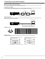
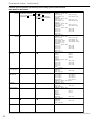
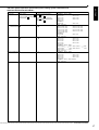
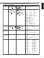
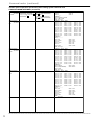
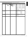
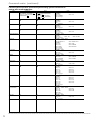
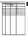
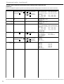
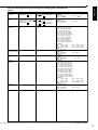
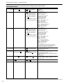
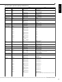
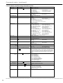
ENGLISH
OTHERS
DIGITAL RECORDER
RS232 PROTOCOL
MODEL
DX-TL800E120
THIS INSTRUCTION MANUAL IS IMPORTANT TO YOU. PLEASE READ IT BEFORE USING YOUR DIGITAL RECORDER.
1
Connecting to a personal computer
■ Connecting with a personal computer
This unit can be remote controlled from a PC equipped with a RS-232C connection. It is also possible to input comments
from a PC for recording comment information along with the video.
♦ Connection via modem
Please use RS-232C Straight cable (9pin) to connect a modem with this unit. The setting of CTS should be set to “HIGH”
or “ON”. Please refer to the instruction manual of a modem for details about connection.
Personal Computer
Telephone line
Unit
ON
MAIN
Y/C
OFF
1
2
3
1
2
3
4 CAMERA IN 5
6
7
8
9
4 CAMERA OUT 5
6
7
8
9
VIDEO OUT
1
2
3
4
5
6
7
8
9
100V
ALARM IN
OUT AUDIO IN
CLOCK ADJ
REC
EMERGENCY
RESERVED
MODE OUT 1
MODE OUT 2
MODE OUT 3
MODE OUT 4
CALL OUT
CALL OUT GND
GND
MAX 30mA
DC 5V OUT
AC IN~
Modem
Modem
RS-232C
RS-232C
RESET
RESET
MIC
GND
RS-232C straight cable (9 pin)
♦ Direct connection
Please use RS-232C Crossover cable (9pin) to connect a modem with a personal computer. RS -232C Crossover cable
differs depending on the personal computer.
Personal Computer
Unit
ON
MAIN
Y/C
OFF
1
2
3
1
2
3
4 CAMERA IN 5
6
4 CAMERA OUT 5
6
7
8
9
7
8
9
VIDEO OUT
1
2
3
4
5
6
7
8
9
100V
ALARM IN
OUT AUDIO IN
MIC
CLOCK ADJ
REC
EMERGENCY
RESERVED
MODE OUT 1
MODE OUT 2
MODE OUT 3
MODE OUT 4
CALL OUT
CALL OUT GND
GND
MAX 30mA
DC 5V OUT
AC IN~
RS-232C
RS-232C
RESET
RESET
GND
RS-232C Crossover cable (9 pin)
♦ RS-232C Terminal
1
5
RS-232C
9
6
Pin NO. Letters Transmission Contents Pin NO. Letters Transmission Contents
2
3
4
5
RXD
Receiving Data
TXD
Transmission Data
DTR
Data Terminal Ready
GND
Signal Ground
6
7
8
DSR
Data Set Ready
RTS
Request To Send
CTS
Clear To Send
♦ RS-232C Cable
Please use the following RS-232C Crossover cable to connect your personal computer to the unit.
1) When RS-232C terminal of personal
computer is D-sub 25 pin
FRAME
RXD 2
TXD 3
DTR 4
GND 5
DSR 6
RTS 7
CTS 8
D-sub 9 pin (unit)
1 FG
2 TXD
3 RXD
4 RTS
5 CTS
6 DSR
7 GND
20 DTR
D-sub 25 pin (Personal computer)
2) When Personal computers RS-232C
terminal is D-sub 9 pin
FRAME
RXD 2
TXD 3
DTR 4
GND 5
DSR 6
RTS 7
CTS 8
D-sub 9 pin
FRAME
2 RXD
3 TXD
4 DTR
5 GND
6 DSR
7 RTS
8 CTS
D-sub 9 pin
•••••••••••••••••••••••••••••••••••••••••••••••••••••••••••••••••••••••••••••••••••••••••••••••••••••••••••••••••••••••••••••••••••••••••••••
60
Command codes
ENGLISH
■ RS-232C settings
Communication related settings of this unit are made in “MODE” and “SETTINGS” of the <RS-232C> screen. Perform
settings so that they are the same as the connecting modem or PC.
When remote controlling this unit from a PC, set “MODE” in the <RS-232C> screen to “REMOTE A” (status
condition change information is returned from the unit) or “REMOTE B” (status condition change information is not
returned from the unit).
Available settings on unit
Synchronization
Asynchronous
Name on Menu
1 Transmission rate at TRANSMISSION
the data received/
sent
1200/2400/4800/
Perform the following settings on the PC
RATE
9600/19200
2 Data bit length
DATA BIT LENGTH
8 BIT/7 BIT
3 Parity bit setting
PARITY BIT
NONE/ODD/EVEN
1 X control
Not available
4 Stop bit length
STOP BIT
1 BIT/2 BIT
2 S parameter
Not available
5 Line feed setting
DELIMITER
CR/CR•LF
3 CS-RS hand-shake
Available
Synchronization
Name on Menu
■ Command code system
2 types of command codes of “direct operation specification” and “false operation panel” can be selected according to
the purpose of the unit.
■ Description of command code systems
♦ Direct operation specification
Control and settings are performed by checking execution, errors, etc., from the status returned from the unit for the
command sent from the PC. This command type is structured by operation setting type commands that sets operations
and menu setting type commands that directly sets various menus.
• Input format
Operation setting type commands are to be sent from the PC for each operation such as power on/off, record, playback,
etc., for the unit.
Menu setting type commands are to be specified for each menu setting of the unit.
As a general rule, do not send commands continuously, but send the next command after checking that the present
command has been executed and completed.
• Response format
After sending a command, the following items can be checked from the status returned from the unit.
1) Command execution result, error type, command name, operation status.
2) For operation setting type commands, the operation mode of the unit can be distinguished by the mode number of the
returned status.
Distinction cannot be made with menu setting type commands. (Mode number is notified only when there is change is
status.)
Example) Turn the Unit ON.
Command
from PC
PW1 #1
Replied status code
from unit to PC
RC
EX,00PW1,03
#2
#2
Meaning
Indicates POWER ON command has been sent.
Indicates that the unit has received a command.
EX : Indicates that a command has been executed.
00 : Indicates that the execution was successful.
PW1 : Indicates response to POWER ON command.
03 : Indicates POWER ON status.
When the unit cannot execute the operation setting type command or menu setting command sent from a PC,
the content is displayed in the error type of the status returned from the unit. Check the error code and take
appropriate measures.
For control type commands such as record, playback, etc., the interval between command transmission and
the actual operation (command execution) may take some time. To prevent the gap between operation and actual
execution, read the status after sending the command and check the transition of the actual execution.
•••••••••••••••••••••••••••••••••••••••••••••••••••••••••••••••••••••••••••••••••••••••••••••••••••••••••••••••••••• Command Codes
61
Command codes (continued)
♦ False operation panel command type
Operations can be specified from a PC as if operating the actual operation panel of the unit while viewing the output
video. Each command is a command type that corresponds to the operation button of the unit.
• Input confirmation type
Send commands as if operate the buttons, JOG dial and SHUTTLE ring of the operation panel. As a general rule, do not
send commands continuously, but send the next command after checking that the present command has been executed
and completed. After sending a command, the command execution result, error type and command name can be checked
by the status returned from the unit. To check the actual execution, view the output screen of the unit on the monitor
screen.
Example) Recorded data is played back using still-frames.
Command
from PC
KKP0 #1
KKB1
KKB4
Replied status code
from unit to PC
RC #2
EX,00KKP0
#2
PC #2
EX,00KKB1
#2
PC #2
EX,00KKB4
#2
#1
#1
Meaning
Indicates that a command equivalent to “push the POWER button” was sent.
Indicates that the unit has received a command.
EX
: Indicates that a command has been executed.
00
: Indicates that the execution was successful.
KKP0 : Indicates that the POWER button was operated.
Indicates that a command equivalent to “push the PLAY button” was sent.
Indicates that the unit has received a command.
EX
: Indicates that a command has been executed.
00
: Indicates that the execution was successful.
KKB1 : Indicates that the PLAY button was operated.
Indicates that a command equivalent to “push the PAUSE button” was sent.
Indicates that the unit has received a command.
EX
: Indicates that a command has been executed.
00
: Indicates that the execution was successful.
KKB4 : Indicates that the PAUSE button was operated.
When using shuttle operation commands, be sure to send the shuttle center command after sending the
operation command. Otherwise, the shuttle operation will be kept until the shuttle center command is sent.
For control type commands such as record, playback, etc., the interval between command transmission and
the actual operation (command execution) may take some time. To prevent the gap between operation and actual
execution, read the status after sending the command and check the transition of the actual execution.
♦ Status condition change information function
Example) Status condition change information of system mode and POWER ON is issued.
Replied status code
from unit to PC
EX,AA,0103 #2
Meaning
EX : Indicates that a command has been executed.
AA : Indicates that status condition change information.
0103 : Indicates that status condition of POWER ON.
When setting “MODE” (
see page 41) to “REMOTE A”, a status condition change information is sent to the
PC when there is change in the unit status. The notification is not sent when setting to “REMOTE B”.
♦ Command receive confirmation function
After executing a received command, the error type during command execution is notified after execution status “EX”.
Error type
00
01
02
03
04
05
06
Contents of Error
Normal
Execute Error
Execute Unable Error
Incorrect command
Incorrect parameter
Excuting the command
Not corresponding
•••••••••••••••••••••••••••••••••••••••••••••••••••••••••••••••••••••••••••••••••••••••••••••••••••••••••••••••••••••••••••••••••••••••••••••
62
ENGLISH
♦ Details of the numbers
#1 : When the setting of DELIMITER on <RS-232C SETTINGS> display is set to CR, carriage return code (0DH) will be
input. If the setting is CR•LF, carriage return code (0DH) and line feed code (0AH) will be input.
#2 : When the setting of DELIMITER on <RS-232C SETTINGS> display is set to CR, carriage return code (0DH) will be
output. If the setting is CR•LF, carriage return code (0DH) and line feed code (0AH) will be output.
: Indicates one number or a character.
*
See “Comment search command code”, page 80.
♦ Command code
• RS-232C [Direct operation specification] operation setting system command form
Commands name
Power
Status
Commands
*
PW
(1) #1
RC
EX,
Notes
(1)
: Power ON/OFF
*0 : OFF
1 : ON
: Error type
** : System mode number
**: Power off
00
03 : Power on
#2
(2)PW
(1),
** * **
(3) #2
(2)
(3)
Recording
Playback
*
PC
(1) #1
**
PB
RC
EX,
#2
RC
EX,
#2
(2)
(1)
(3)
#2
(2)
(1)
(3)
#2
** PC* ,**
(1) #1
** PB* ,**
06 : Setting menu
07 : Copy menu
08 : Search menu
09 : Device unusual situation
0A : Device initialize
0B : Device reconstruction
0F : System unusual situation
(1) : Recording/Stop recording
0 : Stop recording
1 : Recording
(2) : Error type
(3) : Recording mode number
00 : Stop
03 : Stop(pause)
04 : Recording
05 : Pre alarm recording
06 : Alarm recording during pause
07 : Alarm recording during recording
08 : Alarm recording during Pre alarm recording
0A : Recording error
(1) : Playback command
00 : Stop
11 : Playback
12 : Foward speed search 1
13 : Foward speed search 2
14 : Foward speed search 3
15 : Foward speed search 4
16 : Fast foward
17 : Foward field advance
21 : Reverse playback
22 : Reverse speed search 1
23 : Reverse speed search 2
24 : Reverse speed search 3
25 : Reverse speed search 4
26 : Rewind
27 : Reverse field advance
30 : Pause
41 : Forward time date search
42 : Forward record index search
43 : Forward alarm index search
44 : Forward skip search
52 : Reverse record index search
53 : Reverse alarm index search
54 : Reverse skip search
70 : Jump to start point
71 : Jump to end point
(2) : Error type
(3) : Playback mode number
00 : Stop
03 : Playback (single screen)
04 : Reverse playback (single screen)
05 : Playback pause (single screen)
06 : Reverse playback pause (single screen)
07 : Forward speed search (single screen)
08 : Reverse speed search (single screen)
09 : Fast forward (single screen)
0A : Rewind (single screen)
0B : Playback (split display)
0C : Reverse playback (split display)
0D : Playback pause (split display)
0E : Reverse playback pause (split display)
0F : Forward speed search (split display)
10 : Reverse speed search (split display)
11 : Fast forward (split display)
12 : Rewind (split display)
13 : Playback (zoom)
14 : Reverse playback (zoom)
15 : Playback pause (zoom)
16 : Reverse playback pause (zoom)
17 : Forward speed search (zoom)
18 : Reverse speed search (zoom)
19 : Fast forward (zoom)
1A : Rewind (zoom)
1C : Playback error
(1) : 60
(2) : Error type
(3) : Playback mode number (refer to Playback mode)
(4) : Alarm list number (00000 ~ 09999)
(Latest is 00000)
*
**
**
**
**
**
Alarm List search
(1)
** *****
PB
(4) #1
RC
EX,
#2
(2)
(1)
** PB** *****
**
(3) #2
(4),
**
**
**
*****
•••••••••••••••••••••••••••••••••••••••••••••••••••••••••••••••••••••••••••••••••••••••••••••••••••••••••••••••••••• Command Codes
63
Command codes (continued)
• RS-232C [Direct operation specification] operation setting system command form (Continued)
Commands name
Comment search
Status
Commands
(1)
(2)
(3)
(4)
** ** **
PB
*****************
**
** ** ** **
**************** ** **************
*****************
***
* ,**
PB
(5)
RC
EX,
#2
(7)
(1)
(2)
(3)
(4)
(5)
(6) #1
(6)
(8) #2
Notes
: Comment search (80)
(2) : Search direction
00 : Forward
01 : Reverse
(3) : number of search time (01 ~ 99)
(4) : Camera number
00 : CH1
01 : CH2
02 : CH3
03 : CH4
05 : CH6
06 : CH7
07 : CH8
08 : CH9
(5) : Character size (00 - 32)
**
**
**
**
(1)
04 : CH5
**
*****************************
: Comment
*** : Error
type
** : Playback
mode number (refer to Playback mode)
** : Switcher
command
****
0101 : CH1
0102 : CH2
0103 : CH3
0104 : CH4
(6)
(7)
(8)
Switcher
****
SW
(1) #1
RC
EX,
(1)
#2
(2)SW
(1),
** **** **
(3) #2
0105 : CH5
0106 : CH6
0107 : CH7
0108 : CH8
0109 : CH9
0180 : zoom cancel
0181 : zoom
0182 : twice zoom
0184 : four times zoom
0191 : zoom move above
0192 : zoom move down
0193 : zoom move right
0194 : zoom move left
0400 : split 4 screen sequential 0401 : 4(a)
0402 : 4(b)
0403 : 4(c)
0901 : 9a
(2) : Error type
<Case of during playback>
(3) : Playback mode number during playback, display mode
number during another condition.
Playback mode number : refer to playback mode
<Case of another condition>
(3) : Display mode number
03 : single screen
04 : split display
05 : zoom
07 : display error
(1) : Timer recording ON/OFF
0 : Timer off
1 : Timer on
(2) : Error type
(3) : Timer mode number
00 : Timer off
01 : Timer on
02 : Timer error
(1) : Alarm interrupt setting
0 : Alarm interrupt off
1 : Alarm interrupt on
(2) : Error type
(3) : Alarm disable mode number
00 : Alarm disable off
01 : Alarm disable on
(1) : Copy STOP/START
0 : STOP
1 : START
(2) : Error type
(3) : Copy mode number
00 : Stop
02 : Execute
04 : Copy error
(1) : Restore STOP/START
0 : STOP
1 : START
(2) : Error type
(3) : Restore mode number
00 : Stop
02 : Execute
04 : Restore error
(1) : Acquire the recorded period
0 : Main
1 : Copy
(2) : Error type
(3) : Acquire the information mode number
00 : Done
02 : Acquire information error
(4) : Start year
(5) : Start month
(6) : Start day
(7) : Start hour
(8) : Start minute
(9) : Start second
(10) : End year
(11) : End month
(12) : End day
(13) : End hour
(14) : End minute
(15) : End second
(16) : Number of alarm list
(1) : Warning reset
0 : Reset (only display)
(2) : Error type
(3) : System mode number
(refer to Power ON/OFF command)
(1) : Menu initializing, loading or saving
0 : Initialize
1 : Load
2 : Save
(2) : Error type
(3) : System mode number
(refer to Power ON/OFF command)
(1) : Delete the data
01 : Main
03 : Copy
(2) : Error type
(3) : Data delete mode number
00 : Done
02 : Data delete error
**
**
**
Timer
Alarm interrupt
Copy
Restore
Acquire the recorded
period
*
TM
(1) #1
(1) #1
*
(1) #1
*
(1) #1
CP
RP
(2)
(1)
(3) #2
(2)
(1)
(3) #2
(2)
(1)
(3) #2
(2)
(1)
(3) #2
** TM* ,**
*
AD
RC #2
EX,
RC
EX,
#2
RC
EX,
#2
RC
EX,
#2
** AD* ,**
** CP* ,**
** RP* ,**
**
IF
(1) #1
RC #2
EX,
(2)
(1)
(7)
(12)
(8)
*
*
Menu initializing,
loading or saving
MC
Delete the data
CL
(1) #1
RC #2
EX,
**
(1) #1
**
*
**
**
(3)
(4)
(9)
(10)
(13)
(14)
(15)
(16) #2
WC
*
**
**
*
**
**
(5)
** IF** ,** ,** **
** **
** ** ** **
** ,** ** **
*****
(6)
Warning reset
*
**
**
RC #2
EX,
(2)WC
(1)
(3) #2
(2)
(1)
(3) #2
* ,**
** MC* ,**
(1) #1
RC
EX,
#2
(2)
(1)
** CL** ,**
(3) #2
(11)
**
**
**
**
**
**
**
**
**
*****
*
**
**
*
**
**
**
**
**
**
**
**
**
**
**
•••••••••••••••••••••••••••••••••••••••••••••••••••••••••••••••••••••••••••••••••••••••••••••••••••••••••••••••••••••••••••••••••••••••••••••
64
Menu
TIME DATE ADJUST
Commands
<Menu setting>
(1)
(2) #1
DW,
<Inquiry for setting information>
(1) #1
DR,
***** *****
*****
Status
<Writing of menu information>
(3)DW,
RC #2 EX,
** *****
*****
<Reading of menu information>
RC
EX,
** DR,*****
*****
(3)
#2
(1)
*****
(1)
(2) #2
**
*****
*****
**
*****
*****
**
*****
*****
DISPLAY MODE
CLOCK LOCATION
SETTING
CAMERA DISPLAY
CAMERA TITLE/
<Menu setting>
(1)
(2)
MEMO SETTING DW02,
<Inquiry for setting information>
(1)
DR02,
***** *****
*****
<Writing of menu information>
(3)DW02,
RC #2 EX,
**
*****
**
*****
(2) #2
DUPLEX MODE
<Menu setting>
(1)
(2) #1
DISPLAY DW,
<Inquiry for setting information>
(1) #1
DR,
***** *****
*****
*****
<Reading of menu information>
(3)DR02,
RC #2 EX,
(2) #2
*****
<Writing of menu information>
(3)DW,
RC #2 EX,
** *****
*****
<Reading of menu information>
RC
EX,
** DR,*****
*****
(1)
(2) #2
#2
(3)
(2) #2
DAYLIGHT SAVING
Notes
:
00048 : Time (Year)
00049 : Time (Month)
00050 : Time (Day)
00053 : Time (Hour)
00054 : Time (Minute)
00055 : Time (Second)
(2) :
00001 ~ 00099 : Time (Year)
00001 ~ 00012 : Time (Month)
00001 ~ 00031 : Time (Day)
00001 ~ 00023 : Time (Hour)
00000 ~ 00059 : Time (Minute) 00000 ~ 00059 : Time (Second)
(3) : Error type
(1) : 00033
(2) : 00001 ~ 00006
(3) : Error type
(1) : 00034
(2) : 00000 ~ 00383
(3) : Error type
(1) : 00035
(2) : 00000 ~ 00003
00000 : NONE
00001 : NUMBER
00002 : TITLE
00003 : COMMENT
(3) : Error type
(1) :
CH1 : 00080 ~ 00095
CH2 : 00096 ~ 00111
CH3 : 00112 ~ 00127
CH4 : 00128 ~ 00143
CH5 : 00144 ~ 00159
CH6 : 00160 ~ 00175
CH7 : 00176 ~ 00191
CH8 : 00192 ~ 00207
CH9 : 00208 ~ 00223
Memo : 05329 ~ 05344
(2) :
(Refer to CHARACTER CODE LIST)
(3) : Error type
(1) : 05282
(2) :
00000 : NONE
00001 : TOP
00002 : BOTTOM
(3) : Error type
*****
(1)
(2) #2
ENGLISH
• RS-232C [Direct operation specification] menu setting system command form
<TIME DATE/DISPLAY SETTINGS>
(1)
(1)
(1)
**
*****
*****
**
*****
*****
**
***** :: 00052
*****
00000
: OUT
: Error type
**
(1)
(2)
00001 : IN
(3)
•••••••••••••••••••••••••••••••••••••••••••••••••••••••••••••••••••••••••••••••••••••••••••••••••••••••••••••••••••• Command Codes
65
Command codes (continued)
• RS-232C [Direct operation specification] menu setting system command form
<MPX DISPLAY SETTINGS>
Menu
Commands
SPIT 4 SCREEN
<Menu setting>
(1)
(2) #1
SETTING DW,
<Inquiry for setting information>
(1) #1
DR,
***** *****
*****
Status
<Writing of menu information>
(3)DW,
RC #2 EX,
Notes
SPLIT 4(a)
** *****
*****
<Reading of menu information>
RC
EX,
** DR,*****
*****
(1)
(2) #2
#2
(3)
(2) #2
(1)
(1) : 00368 ~ 00371
00368 : Top - left
00369 : Top - right
00370 : Bottom - left
00371 : Bottom - right
SPLIT 4(b)
(1) : 00384 ~ 00387
00384 : Top - left
00385 : Top - right
00386 : Bottom - left
00387 : Bottom - right
SPLIT 4(c)
(1) : 00400 ~ 00403
00400 : Top - left
00401 : Top - right
00402 : Bottom - left
00403 : Bottom - right
(2) : 00000 ~ 00008
00000 : CH1
00001 : CH2
00002 : CH3
00004 : CH4
00005 : CH5
00005 : CH6
00006 : CH7
00007 : CH8
00008 : CH9
(3) : Error type
SPLIT 9
(1) : 00432 ~ 00440
00432 : Top - left
00433 : Top - middle
00434 : Top - right
00435 : Middle - left
00436 : Middle - middle
00437 : Middle - right
00438 : Bottom - left
00439 : Bottom - middle
00440 : Bottom - right
(2) : 00000 ~ 00008
00000 : CH1
00001 : CH2
00002 : CH3
00004 : CH4
00005 : CH5
00005 : CH6
00006 : CH7
00007 : CH8
00008 : CH9
(3) : Error type
(1) : 00480 ~ 00488
00480 : 1
00481 : 2
00482 : 3
00483 : 4
00484 : 5
00485 : 6
00486 : 7
00487 : 8
00488 : 9
(2) : 00000 ~ 00008
00000 : CH1
00001 : CH2
00002 : CH3
00004 : CH4
00005 : CH5
00005 : CH6
00006 : CH7
00007 : CH8
00008 : CH9
(3) : Error type
(1) : 00489
(2) :
00001 : 4ab
00002 : 4abc
(3) : Error type
(1) : 00512 ~ 00521
00512 : SEQ. 1
00513 : SEQ. 2
00514 : SEQ. 3
00515 : SEQ. 4
00516 : SEQ. 5
00517 : SEQ. 6
00518 : SEQ. 7
00519 : SEQ. 8
00520 : SEQ. 9
00521 : SPLIT 4
(2) : 00000 ~ 00030 (second)
(3) : Error type
(1) : 00339
(2) :
00000 : OFF
00001 : ON
(3) : Error type
(1) : 00528 ~ 00536
00528 : 1
00529 : 2
00530 : 3
00531 : 4
00532 : 5
00533 : 6
00534 : 7
00535 : 8
00536 : 9
(2) :
00000 : OFF
00001 : ON
(3) : Error type
(1) : 00544
(2) :
00000 : OFF
00001 : ON
(3) : Error type
*****
*****
*****
*****
SPLIT 9 SCREEN
SETTING
**
*****
*****
SEQUENCE SETTING
SEQ. - CH.
**
*****
*****
SEQUENCE SETTING
SPLIT 4 SETTING
SEQUENCE SETTING
TIME SETTING
INTERLASE
COVERT CAMERA
SETTING
ALARM DISPLAY
**
*****
*****
**
*****
*****
**
*****
*****
**
*****
*****
**
*****
*****
**
•••••••••••••••••••••••••••••••••••••••••••••••••••••••••••••••••••••••••••••••••••••••••••••••••••••••••••••••••••••••••••••••••••••••••••••
66
Menu
Commands
SELECTION
<Menu setting>
(1)
(2) #1
CAMERA NUMBER DW,
<Inquiry for setting information>
(1) #1
DR,
***** *****
*****
Status
<Writing of menu information>
(3)DW,
RC #2 EX,
** *****
*****
<Reading of menu information>
RC
EX,
** DR,*****
*****
#2
(3)
(2) #2
DETECTION
MASK SETTING
SENSITIVITY
(1)
(2) #2
(1)
*****
(1)
00576 : CH1
00578 : CH3
00580 : CH5
00582 : CH7
00585 : CH9
ENGLISH
• RS-232C [Direct operation specification] menu setting system command form
<MOTION DETECTION SETTINGS>
Notes
: 00576 ~ 00584
00577 : CH2
00579 : CH4
00581 : CH6
00583 : CH8
(2) :
00000 : OFF
00001 : ON
(3) : Error type
(1) : 00656 ~ 02383
00656 ~ 00847 : CH1
00848 ~ 01039 : CH2
01040 ~ 01231 : CH3
01232 ~ 01423 : CH4
01424 ~ 01615 : CH5
01616 ~ 01807 : CH6
01808 ~ 01999 : CH7
02000 ~ 02191 : CH8
02192 ~ 02383 : CH9
(2) :
00000 : OFF
00001 : ON
(3) : Error type
(1) : 00608 ~ 00616
00608 : CH1
00609 : CH2
00610 : CH3
00611 : CH4
00612 : CH5
00613 : CH6
00614 : CH7
00615 : CH8
00616 : CH9
(2) : 00000 ~ 00004
00000 : HIGH • • • • • LOW 00001 : HIGH • • • • < LOW
00002 : HIGH • • • < < LOW 00003 : HIGH • • < < < LOW
00004 : HIGH < < < < < LOW
(3) : Error type
(1) : 00624 ~ 00632
00624 : CH1
00625 : CH2
00626 : CH3
00627 : CH4
00628 : CH5
00629 : CH6
00630 : CH7
00631 : CH8
00632 : CH9
(2) : 00001 ~ 00192 (POINT)
(3) : Error type
*****
**
*****
*****
**
*****
*****
MOTION THRESHOLD
**
*****
*****
**
•••••••••••••••••••••••••••••••••••••••••••••••••••••••••••••••••••••••••••••••••••••••••••••••••••••••••••••••••••• Command Codes
67
Command codes (continued)
• RS-232C [Direct operation specification] menu setting system command form
<RECORD SETTINGS>
Menu
RECORD SETTING
PPS
Commands
<Menu setting>
(1)
(2) #1
DW,
<Inquiry for setting information>
(1) #1
DR,
***** *****
*****
Status
<Writing of menu information>
(3)DW,
RC #2 EX,
** *****
*****
<Reading of menu information>
RC
EX,
** DR,*****
*****
#2
(3)
(2) #2
RECORD SETTING
GRADE
(1)
(2) #2
(1)
*****
(1)
04032 : CH1
04034 : CH3
04036 : CH5
04038 : CH7
04040 : CH9
Notes
: 04032 ~ 04040
04033 : CH2
04035 : CH4
04037 : CH6
04039 : CH8
(2) :
65535 : - - - - 00001 : 25P
00003 : 8.333P
00005 : 5P
00008 : 3.125P
00025 : 1P
00100 : 0.25P
(3) : Error type
(1) : 04064 ~ 04072
04064 : CH1
04066 : CH3
04068 : CH5
04070 : CH7
04072 : CH9
(2) :
00000 : SUPER
00002 : STD(STANDARD)
00004 : LONG
(3) : Error type
(1) : 04048 ~ 04056
04048 : CH1
04050 : CH3
04052 : CH5
04054 : CH7
04056 : CH9
(2) :
65535 : - - - - 00001 : 25P
00003 : 8.333P
00005 : 5P
00008 : 3.125P
00025 : 1P
00100 : 0.25P
(3) : Error type
(1) : 04080 ~ 04088
04080 : CH1
04082 : CH3
04084 : CH5
04086 : CH7
04088 : CH9
(2) :
00000 : SUPER
00002 : STD(STANDARD)
00004 : LONG
(3) : Error type
(1) : 05283
(2) :
00000 : ALL
00002 : ALARM PLUS
(3) : Error type
(1) : 03985
(2) : 00000 ~ 03600
00000 : MANUAL
00005 : 5S
00015 : 15S
00045 : 45S
00120 : 2M
00600 : 10M
01800 : 30M
(3) : Error type
*****
**
*****
*****
RECORD SETTING
A-PPS
**
*****
00002 : 12.5P
00004 : 6.25P
00006 : 4.167P
00010 : 2.5P
00050 : 0.5P
00200 : 0.125P
04065 : CH2
04067 : CH4
04069 : CH6
04071 : CH8
00001 : HIGH
00003 : BASIC
04049 : CH2
04051 : CH4
04053 : CH6
04055 : CH8
*****
RECORD SETTING
A-GRADE
**
*****
*****
RECORD SETTING
ALARM MODE
RECORD SETTING
ALARM REC
DURATION
RECORD SETTING
PRE ALARM REC
**
*****
*****
**
*****
*****
00002 : 12.5P
00004 : 6.25P
00006 : 4.167P
00010 : 2.5P
00050 : 0.5P
00200 : 0.125P
04081 : CH2
04083 : CH4
04085 : CH6
04087 : CH8
00001 : HIGH
00003 : BASIC
00001 : ALARM
00002 : 2S
00010 : 10S
00030 : 30S
00060 : 1M
00300 : 5M
01200 : 20M
03600 : 60M
**
***** :: 03986
00001 ~ 00003,00255
*****
00001
: SHORT
00002 : MEDIUM
(1)
(2)
00003 : LONG
(3) : Error type
00255 : OFF
**
•••••••••••••••••••••••••••••••••••••••••••••••••••••••••••••••••••••••••••••••••••••••••••••••••••••••••••••••••••••••••••••••••••••••••••••
68
Menu
Commands
SELECTED PATTERN <Menu setting>
(1)
(2) #1
DW,
<Inquiry for setting information>
(1) #1
DR,
***** *****
*****
Status
<Writing of menu information>
(3)DW,
RC #2 EX,
Notes
: 04112
(2) :
00000 : P1
00001 : P2
00002 : P3
(3) : Error type
*****
*****
(1)
** *****
*****
<Reading of menu information>
RC
EX,
** DR,*****
*****
<Writing of menu information>
RC
EX,
** DW01,**
***** ***** *****
***** ***** *****
*****
<Reading of menu information>
RC
EX,
** DR01,**
***** ***** *****
***** ***** *****
*****
(2) #2
(3)
#2
**
*****
00
: P1 - 1
(1)
(2) #2
TIMER PROGRAM
<Menu setting>
(1)
DW01,
(2)
** *****
***** *****
***** *****
*****
*****
<Inquiry for setting
information>
DR01,
**
(3)
(4)
(5)
(6)
(7)
(8) #1
(1) #1
(9)
#2
(1)
(2)
(3)
(4)
(5)
(6)
(7)
(8) #2
(9)
#2
(1)
(2)
(3)
(4)
(5)
(6)
(7)
(8) #2
ENGLISH
• RS-232C [Direct operation specification] menu setting system command form
<TIMER PROGRAM SETTINGS>
(1)
(1)
: PROGRAM NUMBER
01 : P1 - 2
02 : P1 - 3
03 : P1 - 4
04 : P1 - 5
05 : P1 - 6
06 : P1 - 7
07 : P1 - 8
08 : P2 - 1
09 : P2 - 2
10 : P2 - 3
11 : P2 - 4
12 : P2 - 5
13 : P2 - 6
14 : P2 - 7
15 : P2 - 8
16 : P3 - 1
17 : P3 - 2
18 : P3 - 3
19 : P3 - 4
20 : P3 - 5
21 : P3 - 6
22 : P3 - 7
23 : P3 - 8
(2) : Day of the week
00000 : SUN
00001 : MON
00002 : TUE
00003 : WED
00004 : THU
00005 : FRI
00006 : SAT
00128 : DAY
00129 : SPL
00130 : HOL
00255 : - - (3) : Start time (Hour)
00000 ~ 00023 (Hour)
00255 : - - (4) : Start time (Minute)
00000 ~ 00059 (Time)
00255 : - - (5) : End time (Hour)
00000 ~ 00023 (Hour)
00255 : - - (6) : End time (Minute)
00000 ~ 00059 (Time)
00255 : - - (7) : Selected pattern
00001 : A
00002 : B
00003 : C
00004 : C
00016 : SKIP
00255 : - - (8) : Motion detection setting
00000 : OFF
00001 : ON
00255 : - - (9) : Error type
(1) : 05284 ~ 05287
05284 : A
05285 : B
05286 : C
05287 : D
(2) :
00000 : ALL
00001 : ALARM
00002 : ALARM PLUS
(3) : Error type
(1) : 04400 ~ 04402
04400 : P1
04401 : P2
04402 : P3
(2) :
00000 : SUN
00001 : MON
00002 : TUE
00003 : WED
00004 : THU
00005 : FRI
00006 : SAT
(3) : Error type
(1) : 04416 ~ 04418
04416 : P1
04417 : P2
04418 : P3
(2) :
00000 : SUN
00001 : MON
00002 : TUE
00003 : WED
00004 : THU
00005 : FRI
00006 : SAT
(3) : Error type
(1) : 04432 ~ 04471
04432 : Month
04433 : Date (1 - 1)
04434 : Month
04435 : Date (1 - 2)
04436 : Month
04437 : Date (1 - 3)
04438 : Month
04439 : Date (1 - 4)
04440 : Month
04441 : Date (2 - 1)
04442 : Month
04443 : Date (2 - 2)
04444 : Month
04445 : Date (2 - 3)
04446 : Month
04447 : Date (2 - 4)
04448 : Month
04449 : Date (3 - 1)
04450 : Month
04451 : Date (3 - 2)
04452 : Month
04453 : Date (3 - 3)
04454 : Month
04455 : Date (3 - 4)
04456 : Month
04457 : Date (4 - 1)
04458 : Month
04459 : Date (4 - 2)
04460 : Month
04461 : Date (4 - 3)
04462 : Month
04463 : Date (4 - 4)
04464 : Month
04465 : Date (5 - 1)
04466 : Month
04467 : Date (5 - 2)
04468 : Month
04469 : Date (5 - 3)
04470 : Month
04471 : Date (5 - 4)
(2) :
Month : 00001 ~ 00012
00025 : NONE
Date : 00001 ~ 00031
00025 : NONE
(3) : Error type
*****
*****
*****
*****
*****
*****
TIMER PROGRAM
<Menu setting>
(1)
(2) #1
SETTINGS DW,
ALARM MODE
<Inquiry for setting information>
(1) #1
DR,
***** *****
*****
<Writing of menu information>
(3)DW,
RC #2 EX,
** *****
*****
<Reading of menu information>
RC
EX,
** DR,*****
*****
#2
(3)
(2) #2
TIMER PROGRAM
SETTINGS
DAY OF THE WEEK
START DAY
TIMER PROGRAM
SETTINGS
DAY OF THE WEEK
END DAY
HOLIDAY SETTING
(1)
(2) #2
(1)
*****
**
*****
*****
**
*****
*****
**
*****
*****
**
*****
*****
**
•••••••••••••••••••••••••••••••••••••••••••••••••••••••••••••••••••••••••••••••••••••••••••••••••••••••••••••••••••• Command Codes
69
Command codes (continued)
• RS-232C [Direct operation specification] menu setting system command form
<TIMER PROGRAM SETTINGS> (Continued)
Menu
Commands
TIMER PROGRAM
<Menu setting>
(1)
(2) #1
SETTINGS DW,
REC MODE
<Inquiry for setting information>
(1) #1
DR,
***** *****
*****
Status
<Writing of menu information>
(3)DW,
RC #2 EX,
** *****
*****
<Reading of menu information>
RC
EX,
** DR,*****
*****
(1)
(2) #2
#2
(3)
(2) #2
TIMER PROGRAM
SETTINGS
PPS
Notes
(1)
*****
(1)
04480 : A
04484 : C
:
04482 : B
04486 : D
(2) :
00000 : NORMAL & ALARM
00001 : PRE ALARM
(3) : Error type
(1) : 04560 ~ 04595
04560 : A - CH1
04561 : A - CH2
04562 : A - CH3
04563 : A - CH4
04564 : A - CH5
04565 : A - CH6
04566 : A - CH7
04567 : A - CH8
04568 : A - CH9
04569 : B - CH1
04570 : B - CH2
04571 : B - CH3
04572 : B - CH4
04573 : B - CH5
04574 : B - CH6
04575 : B - CH7
04576 : B - CH8
04577 : B - CH9
04578 : C - CH1
04579 : C - CH2
04580 : C - CH3
04581 : C - CH4
04582 : C - CH5
04583 : C - CH6
04584 : C - CH7
04585 : C - CH8
04586 : C - CH9
04587 : D - CH1
04588 : D - CH2
04589 : D - CH3
04590 : D - CH4
04591 : D - CH5
04592 : D - CH6
04593 : D - CH7
04594 : D - CH8
04595 : D - CH9
(2) :
65535 : - - - - 00001 : 25P
00002 : 12.5P
00003 : 8.333P
00004 : 6.25P
00005 : 5P
00006 : 4.167P
00008 : 3.125P
00010 : 2.5P
00025 : 1P
00050 : 0.5P
00100 : 0.25P
00200 : 0.125P
(3) : Error type
*****
**
*****
*****
TIMER PROGRAM
SETTINGS
GRADE
**
: 04688 ~ 04723
*****
04688
: A - CH1
04689 : A - CH2
(1)
04690 : A - CH3
04691 : A - CH4
04692 : A - CH5
04693 : A - CH6
04694 : A - CH7
04695 : A - CH8
04696 : A - CH9
04697 : B - CH1
04698 : B - CH2
04699 : B - CH3
04700 : B - CH4
04701 : B - CH5
04702 : B - CH6
04703 : B - CH7
04704 : B - CH8
04705 : B - CH9
04706 : C - CH1
04707 : C - CH2
04708 : C - CH3
04709 : C - CH4
04710 : C - CH5
04711 : C - CH6
04712 : C - CH7
04713 : C - CH8
04714 : C - CH9
04715 : D - CH1
04716 : D - CH2
04717 : D - CH3
04718 : D - CH4
04719 : D - CH5
04720 : D - CH6
04721 : D - CH7
04722 : D - CH8
04723 : D - CH9
(2) :
00000 : SUPER
00001 : HIGH
00003 : BASIC
00002 : STD(STANDARD)
00004 : LONG
(3) : Error type
(1) : 04624 ~ 04659
04624 : A - CH1
04625 : A - CH2
04626 : A - CH3
04627 : A - CH4
04628 : A - CH5
04629 : A - CH6
04630 : A - CH7
04631 : A - CH8
04632 : A - CH9
04633 : B - CH1
04634 : B - CH2
04635 : B - CH3
04636 : B - CH4
04637 : B - CH5
04638 : B - CH6
04639 : B - CH7
04640 : B - CH8
04641 : B - CH9
04642 : C - CH1
04643 : C - CH2
04644 : C - CH3
04645 : C - CH4
04646 : C - CH5
04647 : C - CH6
04648 : C - CH7
04649 : C - CH8
04650 : C - CH9
04651 : D - CH1
04652 : D - CH2
04653 : D - CH3
04654 : D - CH4
04655 : D - CH5
04656 : D - CH6
04657 : D - CH7
04658 : D - CH8
04659 : D - CH9
(2) :
65535 : - - - - 00001 : 25P
00002 : 12.5P
00003 : 8.333P
00004 : 6.25P
00005 : 5P
00006 : 4.167P
00008 : 3.125P
00010 : 2.5P
00025 : 1P
00050 : 0.5P
00100 : 0.25P
00200 : 0.125P
(3) : Error type
*****
TIMER PROGRAM
SETTINGS
A-PPS
**
*****
*****
**
•••••••••••••••••••••••••••••••••••••••••••••••••••••••••••••••••••••••••••••••••••••••••••••••••••••••••••••••••••••••••••••••••••••••••••••
70
Menu
Commands
TIMER PROGRAM
<Menu setting>
(1)
(2) #1
SETTINGS DW,
A-GRADE
<Inquiry for setting information>
(1) #1
DR,
***** *****
*****
Status
<Writing of menu information>
(3)DW,
RC #2 EX,
Notes
(1)
** *****
*****
<Reading of menu information>
RC
EX,
** DR,*****
*****
(1)
(2) #2
#2
(3)
(2) #2
ENGLISH
• RS-232C [Direct operation specification] menu setting system command form
<TIMER PROGRAM SETTINGS> (Continued)
(1)
: 04752 ~ 04787
*****
04752
: A - CH1
04753 : A - CH2
04754 : A - CH3
04755 : A - CH4
04756 : A - CH5
04757 : A - CH6
04758 : A - CH7
04759 : A - CH8
04760 : A - CH9
04761 : B - CH1
04762 : B - CH2
04763 : B - CH3
04764 : B - CH4
04765 : B - CH5
04766 : B - CH6
04767 : B - CH7
04768 : B - CH8
04769 : B - CH9
04770 : C - CH1
04771 : C - CH2
04772 : C - CH3
04773 : C - CH4
04774 : C - CH5
04775 : C - CH6
04776 : C - CH7
04777 : C - CH8
04778 : C - CH9
04779 : D - CH1
04780 : D - CH2
04781 : D - CH3
04782 : D - CH4
04783 : D - CH5
04784 : D - CH6
04785 : D - CH7
04786 : D - CH8
04787 : D - CH9
(2) :
00000 : SUPER
00001 : HIGH
00003 : BASIC
00002 : STD(STANDARD)
00004 : LONG
(3) : Error type
(1) : 04102
(2) : 00000 ~ 03600
00000 : MAN
00002 : 2S
00005 : 5S
00010 : 10S
00015 : 15S
00030 : 30S
00045 : 45S
00060 : 1M
00120 : 2M
00300 : 5M
00600 : 10M
01200 : 20M
01800 : 30M
03600 : 60M
(3) : Error type
(1) : 04103
(2) : 00001 ~ 00003
00001 : SHORT
00002 : MEDIUM
00003 : LONG
(3) : Error type
*****
TIMER PROGRAM
SETTINGS
ALARM REC
DURATION
TIMER PROGRAM
SETTINGS
PRE ALARM REC
**
*****
*****
**
*****
*****
**
•••••••••••••••••••••••••••••••••••••••••••••••••••••••••••••••••••••••••••••••••••••••••••••••••••••••••••••••••••• Command Codes
71
Command codes (continued)
• RS-232C [Direct operation specification] menu setting system command form
<INITIAL SET UP/INFORMATION>
Menu
HDD REPEAT REC
Commands
<Menu setting>
(1)
(2) #1
DW,
<Inquiry for setting information>
(1) #1
DR,
***** *****
*****
Status
<Writing of menu information>
(3)DW,
RC #2 EX,
** *****
*****
<Reading of menu information>
RC
EX,
** DR,*****
*****
(1)
(2) #2
#2
(3)
(2) #2
HDD REPEAT PLAY
Notes
(1)
*****
*****
(1)
: 04832
(2) :
00000 : OFF
00002 : STANDBY
(3) : Error type
00001 : ON
**
***** :: 04834
*****
00000
: OFF
00001 : ON
** : Error :type
***** : 04821
*****
00000
: OFF
00001 : ON
: Error type
**
***** :: 04822
*****
00000
: OFF
00001 : ON
** : Error :type
***** : 04817
*****
00000
: OFF
00001 : ON
00002 : ALARM
: Error type
**
: 04848 ~ 04851
*****
04848
: MODE OUT 1
04849 : MODE OUT 2
(1)
(2)
(3)
IM-CHECK PLAY
(1)
(2)
(3)
SEQUENTIAL PLAY
(1)
(2)
(3)
AUDIO RECORDING
(1)
(2)
(3)
MODE OUT
(1)
04850 : MODE OUT 3
(2) :
00000 : OFF
00002 : PLAY
00004 : POWR
00009 : ALARM
(3) : Error type
(1) : 04853
(2) :
00000 : OFF
(3) : Error type
(1) : 04855
(2) :
00000 : OFF
00002 : WARNING
(3) : Error type
(1) : 04864
(2) :
00000 : OFF
(3) : Error type
(1) : 04865
(2) :
00002 : 2%
00006 : 6%
00010 : 10%
00020 : 20%
00040 : 40%
(3) : Error type
(1) : 04880
(2) :
00002 : 2%
00006 : 6%
00010 : 10%
00020 : 20%
00040 : 40%
00255 : OFF
(3) : Error type
(1) : 04102
(2) : 00000 ~ 03600
00060 : 1M
00300 : 5M
01200 : 20M
03600 : 60M
(3) : Error type
(1) : 05360
(2) :
00000 : OFF
(3) : Error type
*****
KEY SOUND
BUZZER
REMAIN HDD
DEVICE
REMAIN HDD
HDD REMAIN
EMERGENCY
REC DURATION
HDD FULL
**
*****
*****
**
*****
*****
**
*****
*****
**
*****
*****
**
*****
*****
**
*****
*****
**
*****
*****
**
04851 : MODE OUT 4
00001 : REC
00003 : REMAIN
00006 : MOTION
00001 : ON
00001 : REMAIN
00003 : ALARM
00001 : HDD
00004 : 4%
00008 : 8%
00015 : 15%
00030 : 30%
00050 : 50%
00004 : 4%
00008 : 8%
00015 : 15%
00030 : 30%
00050 : 50%
00120 : 2M
00600 : 10M
01800 : 30M
00001 : ON
•••••••••••••••••••••••••••••••••••••••••••••••••••••••••••••••••••••••••••••••••••••••••••••••••••••••••••••••••••••••••••••••••••••••••••••
72
Menu
RS-232C
MODE
Commands
<Menu setting>
(1)
(2) #1
DW,
<Inquiry for setting information>
(1) #1
DR,
***** *****
*****
Status
<Writing of menu information>
(3)DW,
RC #2 EX,
RS-233C
SETTINGS
DATA BIT LENGTH
RS-232C
SETTINGS
PARITY BIT
RS-232C
SETTINGS
STOP BIT LENGTH
RS-232C
SETTINGS
DELIMITER
(1)
(2) #2
(3)
(2) #2
RS-232C
SETTINGS
TRANSMISSION RATE
Notes
** *****
*****
<Reading of menu information>
RC
EX,
** DR,*****
*****
#2
ENGLISH
• RS-232C [Direct operation specification] menu setting system command form
<INITIAL SET UP/INFORMATION> (Continued)
(1)
*****
*****
(1)
: 04896
(2) :
00000 : OFF
00002 : REMOTE B
(3) : Error type
**
***** :: 04912
*****
01200
: 1200
00001 : REMOTE A
(1)
(2)
04800 : 4800
19200 : 19200
(3) : Error type
(1) : 04913
(2) :
00007 : 7 BIT
(3) : Error type
(1) : 04914
(2) :
00000 : NONE
00002 : EVEN
(3) : Error type
(1) : 04915
(2) :
00001 : 1 BIT
(3) : Error type
(1) : 04916
(2) :
00000 : CR
(3) : Error type
**
*****
*****
**
*****
*****
**
*****
*****
**
*****
*****
**
02400 : 2400
09600 : 9600
00008 : 8 BIT
00001 : ODD
00002 : 2 BIT
00001 : CR•LF
•••••••••••••••••••••••••••••••••••••••••••••••••••••••••••••••••••••••••••••••••••••••••••••••••••••••••••••••••••• Command Codes
73
Command codes (continued)
• RS-232C [Direct operation specification] menu setting system command form
<SEARCH>
Refer to the playback of [Direct operation specification] operation setting system command form for search execution.
Menu
TIME DATE SEARCH
Commands
<Menu setting>
(1)
(2) #1
DW,
<Inquiry for setting information>
(1) #1
DR,
***** *****
*****
Status
<Writing of menu information>
(3)DW,
RC #2 EX,
** *****
*****
<Reading of menu information>
RC
EX,
** DR,*****
*****
(1)
(2) #2
(3)
#2
(1)
(2) #2
Notes
:
05044 : Search time (Year)
05045 : Search time (Month)
05046 : Search time (Day)
05047 : Search time (Hour)
05048 : Search time (Minute) 05049 : Search time (Second)
(2) :
Year : 00001 ~ 00099
Month : 00001 ~ 00012
Day
: 00001 ~ 00031
Hour : 00001 ~ 00023
Minute : 00000 ~ 00059
Second : 00000 ~ 00059
(3) : Error type
(1) : 05072
(2) : 00001 ~ 00099
(3) : Error type
(1) : 05088
(2) : 00001 ~ 00099
(3) : Error type
(1) :
05060 : List time mask (Year) 05061 : List time mask (Month)
05062 : List time mask (Day)
05063 : List time mask (Hour)
05064 : List time mask (Minute) 05065 : List time mask (Second)
(2) :
Year : 00001 ~ 00099
Month : 00001 ~ 00012
Day
: 00001 ~ 00031
Hour : 00001 ~ 00023
Minute : 00000 ~ 00059
Second : 00000 ~ 00059
None mask : 00238
(3) : Error type
(1) : 05057
(2) :
00000 : TIME DATE
00001 : INDEX
00002 : ALARM INDEX
00003 : ALARM SKIP
00004 : ALARM LIST
(3) : Error type
(1) : 05056
(2) :
00001 : HDD
00003 : CFC
(3) : Error type
*****
(1)
*****
**
*****
*****
**
*****
*****
**
*****
INDEX SEARCH
ALARM INDEX
SEARCH
ALARM LIST SEARCH
DATE/TIME
*****
SEARCH TYPE
<Inquiry for setting information>
(1) #1
DR,
*****
PLAY DEVICE
<Menu setting>
(1)
(2) #1
DW,
<Inquiry for setting information>
(1) #1
DR,
***** *****
*****
<Reading of menu information>
(3)DR,
(1)
RC #2 EX,
**
*****
(2) #2
<Writing of menu information>
(3)DW,
RC #2 EX,
** *****
*****
<Reading of menu information>
RC
EX,
** DR,*****
*****
(1)
(2) #2
#2
(3)
(2) #2
SELECTION
CAMERA NO.
*****
(1)
**
*****
*****
**
*****
*****
**
***** :: 05058
*****
00000
: CH1
(1)
(2)
00002 : CH3
00004 : CH5
00006 : CH7
00008 : CH9
(3) : Error type
00001 : CH2
00003 : CH4
00005 : CH6
00007 : CH8
00032 : ALL
**
•••••••••••••••••••••••••••••••••••••••••••••••••••••••••••••••••••••••••••••••••••••••••••••••••••••••••••••••••••••••••••••••••••••••••••••
74
Menu
COPY
DIRECTION
COPY
MODE
Commands
<Inquiry for setting information>
(1) #1
DR,
*****
<Menu setting>
(1)
(2) #1
DW,
<Inquiry for setting information>
(1) #1
DR,
***** *****
*****
Status
<Reading of menu information>
(3)DR,
(1)
RC #2 EX,
**
*****
(2) #2
*****
Notes
(1)
***** :: 05120
*****
00000
: HDD CFC
: Error type
**
***** :: 05121
*****
00000
: OVERWRITE
** : Error type
(2)
00001 : CFC
HDD
(3)
<Writing of menu information>
(3)DW,
RC #2 EX,
(1)
** *****
*****
<Reading of menu information>
RC
EX,
** DR,*****
*****
(1)
(2) #2
#2
ENGLISH
• RS-232C [Direct operation specification] menu setting system command form
<COPY>
(3)
(1)
(2)
00001 : FIFO
(3)
(2) #2
COPY
START/END
(1) :
05136 : Copy start time (Year)
05137 : Copy start time (Month)
05138 : Copy start time (Day)
05139 : Copy start time (Hour)
05140 : Copy start time (Minute)
05141 : Copy start time (Second)
05142 : Copy end time (Year)
05143 : Copy end time (Month)
05144 : Copy end time (Day)
05145 : Copy end time (Hour)
05146 : Copy end time (Minute)
05147 : Copy end time (Second)
(2) :
Year : 00001 ~ 00099
Month : 00001 ~ 00012
Day
: 00001 ~ 00031
Hour : 00001 ~ 00023
Minute : 00000 ~ 00059
Second : 00000 ~ 00059
(3) : Error type
(1) : 05126
(2) :
00000 : START•END
00001 : START
(3) : Error type
(1) : 05152
(2) :
00000 : OVERWRITE
00001 : FIFO
(3) : Error type
(1) :
05168 : Restore start time (Year)
05169 : Restore start time (Month)
05170 : Restore start time (Day)
05171 : Restore start time (Hour)
05172 : Restore start time (Minute)
05173 : Restore start time (Second)
05174 : Restore end time (Year)
05175 : Restore end time (Month)
05176 : Restore end time (Day)
05177 : Restore end time (Hour)
05178 : Restore end time (Minute)
05179 : Restore end time (Second)
(2) :
Year : 00001 ~ 00099
Month : 00001 ~ 00012
Day
: 00001 ~ 00031
Hour : 00001 ~ 00023
Minute : 00000 ~ 00059
Second : 00000 ~ 00059
(3) : Error type
(1) : 05126
(2) :
00000 : START•END
00001 : START
(3) : Error type
*****
*****
COPY
TRANSFER PERIOD
RESTORE
MODE
RESTORE
START/END
**
*****
*****
**
*****
*****
**
*****
*****
RESTORE
TRANSFER PERIOD
**
*****
*****
**
•••••••••••••••••••••••••••••••••••••••••••••••••••••••••••••••••••••••••••••••••••••••••••••••••••••••••••••••••••• Command Codes
75
Command codes (continued)
• RS-232C [Direct operation specification] menu setting system command form
<ANOTHER SETTINGS>
Menu
Commands
RECORDING
<Inquiry for setting information>
(1) #1
PATTERN DR,
*****
CHECK THE
MD?
CONDITION
CHECK THE
ME?
CONDITION
ACQUIRE THE
UTO?
ELAPSED TIME
Status
<Writing of menu information>
(3)DR,
RC #2 EX,
Notes
: 05268
(2) :
(1)
(2) #2
00000 : NORMAL
(3) : Error type
(1) : System condition
RC #2
(2) : Key lock condition
(26)MD,
(1)
(2)
(3)
(4)
EX,
(3) : Remote / local condition
(5)
(6)
(7)
(8)
(9)
(4) : Timer condition
(10)
(11)
(12)
(13)
(14)
(5) : Alarm interrupt condition
(15)
(16)
(17)
(18)
(19)
(6) : Menu condition
(20)
(21)
(22)
(23)
(24)
(7) : Recording condition
(25) #2
(8) : Playback condition
(9) : Display condition
(Each status corresponds to the last two
(10) : Motion detection condition
digits of each operating mode within
(11) : Back up condition
the condition change notification system.)
(12) : Copy condition
(13) : Restore condition
(14) : Device control condition
(15) : Acquire information condition
(16) : Delete device condition
(17) : Data reset condition
(18) ~
(25) : Reserved
(26) : Error type
(1) : System condition
RC #2
(2) : Key lock condition
(26)ME,
(1)
(2)
(3)
(4)
EX,
(3) : Remote / local condition
(5)
(6)
(7)
(8)
(9)
(4) : Timer condition
(10)
(11)
(12)
(13)
(14)
(5) : Alarm interrupt condition
(15)
(16)
(17)
(18)
(19)
(6) : Menu condition
(20)
(21)
(22)
(23)
(24)
(7) : Recording condition
(25) #2
(8) : Playback condition
(9) : Display condition
(Each status corresponds to the last two
(10) : Motion detection condition
digits of each operating mode within
(11) : Back up condition
the condition change notification system.)
(12) : Copy condition
(13) : Restore condition
(14) : Device control condition
(15) : Acquire information condition
(16) : Delete device condition
(17) : Data reset condition
(18) ~
(25) : Reserved
(26) : Error type
(When there is a lag in response time of the unit during
condition change, sending this command will read RS-232C
status after readying the unit for response by clearing
all remaining commands in the reception buffer. )
(1) : Elapsed time
RC #2
(2)
0000000000 ~ 9999999999 (Hour)
UTO?,
EX,
(2) : Error type
(1) #2
(1) : Camera number
RC #2
(4)COMD,
(1)
(2)
00 : CH1
01 : CH2
02 : CH3
03 : CH4
04 : CH5
EX,
05 : CH6
06 : CH7
07 : CH8
08 : CH9
(2) : Character size (00 - 32)
(3) #2
(1)
*****
*****
**
**
** ** ** ** ** **
**
** **** ** ** **
**
** ** ** ** **
**
** ** ** ** **
****
** ** ** ** **
**
**
**
**
**
**
**
**
**
**
**
**
** **
**
**
** ** ** ** ** **
**
** **** ** ** **
**
** ** ** ** **
**
** ** ** ** **
****
** ** ** ** **
**
**
**
**
**
**
**
**
**
**
**
**
** **
**
**
*****
**
*****
*********
**********
**
**
*
** ** *******
** ** *****
**************** **
******************
*********
**
*********
*****************************
: Comment
*** : Error
type
**
: Camera number
RC
COMS,
**: CH1 01 : CH2 02 : CH3 03 : CH4 04 : CH5
**
00
EX,
** COMS,**
05 : CH6
06 : CH7
07 : CH8
08 : CH9
: Error type
**
RC
DC
00DC
EX,
**
WRITE COMMENT
COMD,
DATA INFORMATION
(1)
(2)
(3) #1
(3)
(4)
WRITE COMMENT
(1) #1
(1)
#2
(2)
(1) #2
(2)
DELETE THE
COMMENT DISPLAY
#1
#2
(2)
#2
•••••••••••••••••••••••••••••••••••••••••••••••••••••••••••••••••••••••••••••••••••••••••••••••••••••••••••••••••••••••••••••••••••••••••••••
76
Button
POWER
REC/STOP
KKR0
KKR1
STOP
KKB0
PLAY
KKB1
REV.PLAY
(REVERSE PLAY)
PAUSE
KKB2
TIMER
KKT0
KKB4
KKT1
ZOOM
KKZ
SPLIT/SEQUENCE
KKE
Camera number
KKD01
KKD02
KKD03
KKD04
KKD05
KKD06
KKD07
KKD08
KKD09
LOCK
KKL0
KKL5
SET UP
KKM
COPY
KKC
SEARCH
KKK0
WARNING RESET
KKW0
KKW5
ALARM INTERRUPT
JOG
KKA
KKJ0
KKJ1
SHUTTLE
Status
Commands
KKP0
KKS00
KKS01
KKS02
KKS03
KKS04
KKS11
KKS12
KKS13
KKS14
RC
EX,
RC
EX,
RC
EX,
RC
EX,
RC
EX,
RC
EX,
RC
EX,
RC
EX,
RC
EX,
RC
EX,
RC
EX,
RC
EX,
RC
EX,
RC
EX,
RC
EX,
RC
EX,
RC
EX,
RC
EX,
RC
EX,
RC
EX,
RC
EX,
RC
EX,
RC
EX,
RC
EX,
RC
EX,
RC
EX,
RC
EX,
RC
EX,
RC
EX,
RC
EX,
RC
EX,
RC
EX,
RC
EX,
RC
EX,
RC
EX,
RC
EX,
RC
EX,
RC
EX,
RC
EX,
**
**
**
**
**
**
**
**
**
**
**
**
**
**
**
**
**
**
**
**
**
**
**
**
**
**
**
**
**
**
**
**
**
**
**
**
**
**
**
(2)KKP0
ENGLISH
• RS-232C [False operation panel] command form
Notes
POEWR ON/OFF
(2) : Error type
RECORDING
**
(2)KKR0
(2)KKR1
(2)KKB0
(2)KKB1
(2)KKB2
(2)KKB4
STOP RECORDING
(2) : Error type
STOP PLAYBACK
(2) : Error type
PLAYBACK
(2) : Error type
REVERSE PLAYBACK
(2) : Error type
PAUSE
(2) : Error type
TIMER ON
**
**
**
**
**
(2)KKT0
(2)KKT1
(2)KKZ
(2)KKE
TIMER OFF
(2) : Error type
ZOOM
(2) : Error type
SPLIT / SEQUENCE
(2) : Error type
CH1
**
**
**
(2)KKD01
CH2
(2)KKD02
CH3
(2)KKD03
CH4
(2)KKD04
CH5
(2)KKD05
CH6
(2)KKD06
CH7
(2)KKD07
CH8
(2)KKD08
CH9
(2)KKD09
(2) : Error type
SIMPLE LOCK
**
(2)KKL0
(2)KKL5
(2)KKM
(2)KKC
(2)KKK0
PASSWORD LOCK
(2) : Error type
MENU
(2) : Error type
COPY
(2) : Error type
SEARCH
(2) : Error type
WARNING RESET
**
**
**
**
(2)KKW0
(2)KKW5
(2)KKA
WARNING RESET 5 second pressing
(2) : Error type
ALARM INTERRUPT
(2) : Error type
JOG right turn
**
**
(2)KKJ0
(2)KKJ1
JOG left turn
(2) : Error type
SHUTTLE center
**
(2)KKS00
SHUTTLE right 1
(2)KKS01
SHUTTLE right 2
(2)KKS02
SHUTTLE right 3
(2)KKS03
SHUTTLE right 4
(2)KKS04
SHUTTLE left 1
(2)KKS11
SHUTTLE left 2
(2)KKS12
SHUTTLE left 3
(2)KKS13
(2)KKS14
SHUTTLE left 4
(2) : Error type
(Send SHUTTLE center command before send this command. )
**
•••••••••••••••••••••••••••••••••••••••••••••••••••••••••••••••••••••••••••••••••••••••••••••••••••••••••••••••••••• Command Codes
77
Command codes (continued)
• RS-232C Status condition change information system
Mode
System mode
Status
EX,AA,
Notes
(1)
: System mode
****
0100 : Power off
(1) #2
****
0103 : Power on
0106 : Setting menu
0107 : Copy menu
0108 : Search menu
0109 : Device unusual situation
010A : Device initialize
010B : Device reconstruction
010F : System unusual situation
(1) : Timer mode
0500 : Timer off
0501 : Timer on
0502 : Timer error
(1) : Alarm disable mode
0600 : Alarm disable off
0601 : Alarm disable on
(1) : Recording mode
0800 : Stop
0803 : Stop(pause)
0804 : Recording
0805 : Pre alarm recording
0806 : Alarm recording during pause
0807 : Alarm recording during recording
0808 : Alarm recording during Pre alarm recording
080A : Recording error
(1) : Playback mode
0900 : Stop
0903 : Playback (1)
0904 : Reverse playback (1)
0905 : Playback pause (1)
0906 : Reverse playback pause (1)
0907 : Forward speed search (1)
0908 : Reverse speed search (1)
0909 : Fast forward (1)
090A : Rewind (1)
090B : Playback (2)
090C : Reverse playback (2)
090D : Playback pause (2)
090E : Reverse playback pause (2)
090F : Forward speed search (2)
0910 : Reverse speed search (2)
0911 : Fast forward (2)
0912 : Rewind (2)
0913 : Playback (3)
0914 : Reverse playback (3)
0915 : Playback pause (3)
0916 : Reverse playback pause (3)
0917 : Forward speed search (3)
0918 : Reverse speed search (3)
0919 : Fast forward (3)
091A : Rewind (3)
091C : Playback error
(1) : Single screen , (2) : Split display, (3) : Zoom
(1) : Display mode
0A07 : Display error
(1) : Motion detection mode
0B05 : Motion detection error
(1) : Copy mode
0D00 : Stop
0D02 : Execute
0D04 : Copy error
(1) : Restore mode
0E00 : Stop
0E02 : Execute
0E04 : Restore error
(1) : Acquire information mode
1000 : Done
1002 : Acquire information
(1) : Data delete mode
2000 : Done
2002 : Data delete error
Timer mode
****
Alarm disable mode
****
****
Recording mode
Playback mode
****
Display mode
****
****
****
Motion detection mode
Copy mode
****
Restore mode
Acquire the information
mode
Data delete mode
Inform the NO SIGNAL
condition
****
****
EX,AB11,
************* ******************************
the NO SIGNAL condition
** :theInformation
****************** Output
NO SIGNAL condition (3 : Having signal, 2 : Judge having signal
*
1 : Judge not having signal, 0 : Not having signal) about 9CH(32CH) when
(1)
(1) #2
**
(1) #2
**
Inform the error
warning
EX,AB,
Inform the data
falsification error
Inform the renewal of
Alarm number
Inform the position
EX,AB51,
(1) #2
**
EX,AC11,
*****
EX,AC,
** ,***
(1) #2
(1)
the condition changes. But this information is effective to the camera which is
recording, so the information about the camera whitch is not recording is
indefinite.
(1) :
12 : REC R/W ERROR
13 : REC SYSTEM ERROR
32 : COPY R/W ERROR
33 : COPY SYSTEM ERROR
34 : COPY OVERWRITE ERROR
35 : COPY EARLY WARNING ERROR
36 : COPY OVERWRITE WARNING
42 : RESTORE R/W ERROR
43 : RESTORE SYSTEM ERROR
(1) : Camera number
(2) #2
**
: Renewal of Alarm number
*****
(Output when the Alarm number is renewed.)
**: Main: Position
12
device recording position
(1)
(1)
32 : Copy device recording position
42 : Restore device recording position
(2) : 000 ~ 100 (%)
***
•••••••••••••••••••••••••••••••••••••••••••••••••••••••••••••••••••••••••••••••••••••••••••••••••••••••••••••••••••••••••••••••••••••••••••••
78
.
(Space)
00032
!
"
#
$
%
&
'
(
00033
00034
00035
00036
00037
00038
00039
00040
+
,
-
.
/
00042
00043
00044
00045
00046
00047
7
00055
8
00056
9
00057
ENGLISH
♦ Character code list
Character
Character code
00012
Character
Character code
00041
Character
Character code
:
;
<
=
>
?
@
00058
00059
00060
00061
00062
00063
00064
Number
Character code
0
00048
1
00049
2
00050
3
00051
4
00052
5
00053
6
00054
Alphabet
A
Character code 00065
B
C
D
E
F
G
H
I
J
K
L
M
00066
00067
00068
00069
00070
00071
00072
00073
00074
00075
00076
00077
Alphabet
Character code
N
O
P
Q
R
S
T
U
V
W
X
Y
Z
00078
00079
00080
00081
00082
00083
00084
00085
00086
00087
00088
00089
00090
Alphabet
Character code
a
b
c
d
e
f
g
h
i
j
k
l
m
00097
00098
00099
00100
00101
00102
00103
00104
00105
00106
00107
00108
00109
Alphabet
Character code
n
o
p
q
r
s
t
u
v
w
x
y
z
00110
00111
00112
00113
00114
00115
00116
00117
00118
00119
00120
00121
00122
)
•••••••••••••••••••••••••••••••••••••••••••••••••••••••••••••••••••••••••••••••••••••••••••••••••••••••••••••••••••• Command Codes
79
Comment search
Characters (character strings) inputted from a PC connected to this unit by RS-232C connection can be recorded as
comments along with the video/audio. Recorded comments can be displayed during playback. Furthermore, recorded
comments can be specified for search so that the video with the comment can be played back from the beginning.
■ Comment search command code
Menu
Comment search
Status
Commands
(1)
(2)
(3)
(4)
** ** ** **
** ************* ** PB** ** ** **
**************** ** **************
*****************
***
*
PB
(5)
RC
EX,
#2
(7)
(1)
(2)
(3)
(5)
(6) #1
(6) #2
(4)
Notes
: Comment search (80)
(2) : Search direction
00 : Forward
01 : Reverse
(3) : number of search time (01 ~ 99)
(4) : Camera number
00 : CH1
01 : CH2
02 : CH3
03 : CH4
05 : CH6
06 : CH7
07 : CH8
08 : CH9
(5) : Character size (00 - 32)
**
**
**
**
(1)
04 : CH5
**
*****************************
: Comment
*** : Error
** : Cameratypenumber
**
00 : CH1
01 : CH2
02 : CH3
03 : CH4
04 : CH5
(6)
(7)
(1)
(2)
(1)
** ** ******* RC
**************** EX,** COMD,** ** ***** 05 : CH6 06 : CH7 07 : CH8 08 : CH9
******************
*********
** : Character size (00 - 32)
*********
*****************************
: Comment
*** : Error
type
**
: Camera number
RC
COMS,
**
**
00 : CH1
01 : CH2
02 : CH3
03 : CH4
04 : CH5
EX,
** COMS,**
05 : CH6
06 : CH7
07 : CH8
08 : CH9
** : Error type
RC
DC
EX,
** 00DC
WRITE COMMENT
COMD,
DATA INFORMATION
#2
(4)
(1)
(2)
(3) #1
(3) #2
(2)
(3)
(4)
WRITE COMMENT
(1) #1
(1)
#2
(2)
(1) #2
(2)
DELETE THE
COMMENT DISPLAY
#1
#2
(2)
#2
■ Characters can be used for comment search
Alphabet
Character
Number
A B C D E F G H I
" # $ % & ' (
(Space) !
0 1 2 3 4 5 6 7 8
J K L M N O P Q R S T U V W X Y Z
)
+ , - . / : ; < = > ? @
9
••••••••••••••••••••••••••••••••••••••••••••••••••••••••••••••••••••••••••••••••••••••••••••••••••••••••••••••••••••••••••••••••••••••••••••
80
ENGLISH
■ Sample operation
1) Record character string “ABCDEF” as a comment along with the video. (When “DELIMITER” in the <RS-232C SETTING> screen is set to “CR”.)
The operation is performed on a PC.
1. Set the character (or characters string) to be recorded;
2. Record the selected character(s).
By using the COMS command, characters which have been set once can be recorded any number of times. To record a
different character set, use the COMD command.
Up to 32 characters can be inputted.
2) Display the recorded comment.
1. Select <SETTINGS> } “CAMERA DISPLAY” in the <TIME DATE/DISPLAY SETTINGS> screen. Display “COMMENT” and confirm.
The number of characters displayed on the screen : all 32 for single screen, first 10 for SPLIT4, and first 6 for
SPLIT9.
3) Skip to the scene with characters “ABCDEF”. (When “DELIMITER” in the <RS-232C SETTINGS> screen is set to
“CR”.)
The operation is performed on a PC.
After comment search, playback is performed using single screen display.
Comment search can be performed even when playback is stopped, during still frame playback, playback or
recording.
The unit will fast forward or rewind until it finds the character string, then shift into still frame mode.
Comment searches may be time-consuming as the process involves searching through all the data.
If the unit does not find the character string, it will stop automatically.
•••••••••••••••••••••••••••••••••••••••••••••••••••••••••••••••••••••••••••••••••••••••••••••••••••••••••••••••••••••• Comment search
81