1
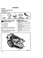
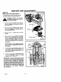
6.5 Horsepower
KEY START
HIGHWHEEL WEEDTRIMMER:
MODEL NO.
536.773520
Caution:
Read and follow all Safety Rules
and Operating Instructions before
first use of this product,
SEARS,
712344
ROEBUCK
02/10/99
AND CO., Hoffman
Estates,
IL 60179 U.S
TABLE OF CONTENTS
WARRANTY STATEMENT
......
SAFETY RULES ...............
INTERNATIONAL
SYMBOLS ....
ASSEMBLY
...................
OPERATION ...................
MAINTENANCE
................
SERVICE AND ADJUSTMENT
..,
2
3
5
6
9
13
16
TROUBLE
SHOOTING
CHART
..
21
SLOPE GUIDE .................
23
REPAIR PARTS ................
24
ENGINE
29
SPANISH
REPAIR PARTS ........
(ESPANOL)
..........
PARTS ORDERING/SERVICE
38
...
64
WARRANTY STATEMENT
LIMITED
TWO-YEAR
WARRANTY
ON CRAFTSMAN
WEEDTRIMMER
For two years from the date of purchase, when this CraftsmanWeedtrimmer is maintained,
lubricated,and tuned ,up according to the operating and maintenance instructionsin the
owner's manual, Craftsman wilt repair, free of charge, any defect in material or workmanship.
If this CraftsmanWeedtrimmer is used for commercial or rental purposes, this warrantyappliesfor only 90 days from the date of purchase.
This warranty does not cover the following;
Expendable items which become worn during normal use, such as spark plugs, etc.
•
Repair necessary because of operator abuse or negligence,includingbent crankshafts
and the failure to maintain the equipmentaccording to the instructionscontainedin the
owner's
manual.
WARRANTY SERVICE IS AVAILABLE BY RETURNING THE CRAFTSMAN WEED°
TRIMMER TO THE NEAREST CRAFTSMAN SERVICE CENTER/DEPARTMENT IN THE
UNITED STATES. THIS WARRANTY APPLIES ONLY WHILE THIS PRODUCT IS IN USE
IN THE UNITED STATES.
This warranty gives you specific legal rights, and you may also have other rights which may
vary from state to state.
Sears, Roebuck and Co., D81"7WA, Hoffman Estates. IL 60179
of
defects
to cause cancer, birth
or other reproductive
harm.
tP
IMPORTANT: This unit |a equipped with an internal combustion engine and must not be
used on or near any unimproved forest-covered, brush-covered or grass-covered land
unless the engine's exhaust system is equipped with a spark arrester meeting
applicable local or state laws (if any). If a spark arrester is used, it must be maintained in
effective working order by the operator.
In the State of California the above is required by law (Section 4442 of the California
Public Resources Coda). Other states may have similar laws. Federal laws apply on federal lands. See an Authorized Service Center for a spark arrester for the muffler,
712344
2
SAFETY RULES
Safe Operation
A
Practices for
Look for this
symbol
to point
out important
safety precautions.
It ARNING:
means: "Attention!
Become
Alert!
Your Safety
Is Involved."
L
General Operation
1.
Read, understand, and follow all instructions on the machine and in the manual(s).
Be thoroughly familiar with the controls and
the proper use of the trimmer before starting.
Familiarize yourself with all of the safety
and operating decals on th_s equipment
and on any of its attachments or accessories.
Do not put hands or feet near or under rotating parts,
Only allow responsible individuals, who are
femi{iar with the instructions, to operate the
trimmer.
_nspect the area where the trimmer is to be
used. Your equipment can propel small objects at high speed causing personal injury
or property damage.
Stay away from
breakable objects, such as house windows, auto glass, greenhouses, etc,
Keep the area of operation clear of all persons, particularly small children, end pets.
Wear appropriate clothing such as a longsleeved shirt or jacket, Also wear long trousers or slacks, Do not wear shorts,
2.
3.
4.
5.
6.
7,
8.
Trimmer.
Do not wear loose clothing which could get
caught in this equipment.
9. Always wear safety goggles or safety
glasses with side shields when operating
trimmer to protect your eyes from foreign
objects which can be thrown from the unit.
10. Always wear work gloves and sturdy footwear. Leather work shoes or short boots
Only use accessories approved by the
manufacturer.
15. Operate only in daylight or good artificial
light.
16. Do not operate the trimmer while under the
influence of alcohol,drugs or other medication which can cause drowsiness or effect
your abilityto operate this machinesafely.
17. Never operate trimmer in wet grass. Always be sure of your footing; keep a firm
hold on the handle and walk; never run.
18. Before each use, inspectthe throttle controt lever end cable. Make sure that the
cable is free and that the lever is not damaged. Also check the cable linkage running
to the carburetor for kinks, loose fittings,
end obstructions. Verify that the control
bailis working properly.
19. Stopthe rotatingtrimmerhead when crossinggravel drives, walks, or roads. Wait for
the cutting linesto stop rotating.
20. Watch for traffic when operating near, or
when crossing roads.
21. Stop the engine (motor) whenever you
leave the equipment, before cleaning repairing or inspecting the unit, be sure the
trimmer head and all moving parts have
stopped. Let the engine cool, disconnect
the spark plug wire and move it away from
the spark plug.
22. If the equipmentshouldstart to vibrate abnormally,stop the engine (motor), disconnectthe spark plug wire and prevent itfrom
touchingthe spark plug. Check immediately for the cause. Vibration is generally a
warningof trouble.
23. After striking a foreign object, stop the engine (motor). Remove the wire from the
spark plug. Inspect the trimmer for damage. If damaged, repair beforestarting and
operatingthe trimmer.
24. Never leave the trimmer unattendedwhen
the engine is running. Remove the wire
from the spark plug.
25. Regularly inspectthe trimmer. Make sure
parts are not bent, damaged or loose.
work well for most people. These will protect the operator's ankles and shins from
smell sticks, splinters, and other debris,
and improve traction.
11. It is advisable to wear protective headgear
to prevent the possibility of being struck by
small flying particles, or being struck by low
hanging branches, twigs, or other objects
which may be unnoticed by the operator.
12, Do not operate the trimmer without proper
guards or other safety protective devices
in place.
13, Use this equipment for its intended purII. Slope Operation
pose only.
14. See manufacturer's
instructions for proper
Slopes are a majorfactor related to slip and fall
operation and installation of accessories.
accidents which can result in severe injury,All
712344
3
SAFETY RULES
slopes require extra caution. If you feel uneasy
on a slope, do not trim it,
c.
Never refuelthe machine indoors,
Do trim across the face of slopes; never up and
down. Do not trim excessively steep slopes
(ma.%lmum 15 degrees) or areas where the
ground is very rough. See the "Guide" in the
back of this manual to check a slope. Exercise
extreme caution when changing direction on
slopes.
d.
Never store the machine or fuel container inside where there is an open
flame, such as a water heater,
2.
3.
Do remove objects such as rocks, tree limbs,
etc.
Do watch for holes, ruts, or bumps. Tall grass
can hide obstacles.
Do not trim near drop-offs, ditches, or embankments. The operator could lose footing or balance,
4.
Do not trim excessively steep slopes.
Do not trim on wet grass. Reduced footing
could cause slipping,
5.
IlL Children
Tragic accidents can occur if the operator is not
alert to the presence of children. Children are
often attracted to the trimmer and the trimming
activity. Never assume that children will remain
where you last saw them,
1.
2.
Before and while moving backwards,
behind and down for small children.
4.
Nev_ allow children to operate the trimmer.
Use extra care when approaching blind
corners, shrubs, trees, or other objects that
may obscure vision.
On electric start models, remove the ignition key to prevent accidental starting when
the trimmer is not is use.
6.
7.
Keep children out of the trimming area and
under the watchful care of a responsible
adult.
Be alert and turn trimmer off if children enter the area.
3.
5.
6.
look
8.
9.
10.
11.
IV. Service
1.
12.
Use extra care in hand$inggaso$ineand
other fuels: They are flammable and vaporsare explosive.
a. Use onlyan approvedcontainer.
13.
b. Never remove gas cap or add fuel with
the engine running. Allow engine to
cool before refueling.Do not smoke.
712344
Never run an engine indoors or inside a
closed area.
Never make adjustments or repairs with
the engine (motor) running. Disconnect the
spark plug wire, and keep the wire away
from the plug to prevent accidental starting
(remove the ignition key if equipped with an
electric start), Always wear eye protection
when you make adjustments or repairs.
Check the trimmer head and engine
mounting bolts at frequent intervals for
proper tightness.
Keep all nuts and bolts tight and keep
equipment in good condition.
Check
mounting hardware on trimmer head every
time you change trimmer line and prior to
each use.
Never tamper with safety devices. Check
their proper operation regularly.
When servicing or repairing the trimmer, do
not tip the machine over or up unless specifically instructed to do so in this Manual.
Service and repair procedures can be done
with the trimmer in an upright position.
Some procedures will be easier if the machine is lifted on a raised platform or working surface.
To reduce fire hazard, keep trimmer free of
grass, leaves, or other debris build-up.
Clean up oil or fuel spillage. Allow trimmer
to cool before storing.
Stop and inspect the equipment if you
strike an object. Repair, if necessary, before restarting.
Always disconnect spark plug wire before
cleaning, repairing, or adjusting.
Do not change the engine governor setting
or over-speed the engine,
Clean and replace safety and instruction
decals as necessary.
To guard against engine over-heating, always hav_ engine debris lister mounted
and clean.
14, Inspect trimmer before storage.
15, Use only original equipment or authorized
replacement parts.
4
SAFETY RULES
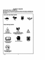
INTERNATIONAL
SYMBOLS
IMPORTANT: Many of the following symbols are located on your unit or on literature supplied with the product. Before you operate the unit, learn and understand the purpose for
each symbol.
ControlAnd OperatingSymbols
Slow
Fast
Fuel
OII
WARNING
Rotating Parts. Stop Engine.
Disconnect Spark Wire Before
Making Adjustments.
WARNING
SafetyWarningSymbols
A
WARNING
Thrown Objects.
Keep Bystanders Away.
IMPORTANT
Read Owner's Manual
Before Operating
This Machine.
WARNING
Wear Eye Protection
WARNING
Never Operate Up Or
Down Slopes. Operate
Across Slopes.
712344
5
STOP
ASSEMBLY
ASSEMBLY
CONTENTS
OF PARTS
1 Owner's Manual
- Parts Bag
BAG
(Not shown actual size)
I
1-wTr-...2,,a-
TO REMOVE THE
TRIMMER FROM CARTON
glasses or eye
shields
while
asWARNING:
Always
wear
safety
sembling the trimmer.
TOOLS REQUIRED
1 - Knife to cut carton.
1 - T-Handle
I
'
1.
Remove the parts bag and all loose parts
from carton.
2.
Remove the packing material positioned
aroundthe unit.
3.
Cut down all four corners of the cartonand
lay the side panelsflat.
Pull the trimmer out of the carton and off
the base pad.
Wrench.
4.
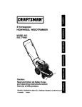
Figure 1 shows the trimmer completely assembled and positioned in the carton for shipment.
References to the right or left hand side of the
trimmer are from the viewpoint of the operator's position behind the unit,
5.
Remove packing materialfrom aroundthe
trimmer head.
6.
Remove protective plastic from front of
frame.
Figure 1
712344
6
ASSEMBLY
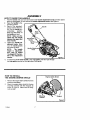
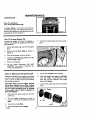
HOW TO RAISE THE HANDLE
1.
2.
3.
Hold the handle with one hand and loosen both handle adjustment
knobs until the ratchet
teeth are disengaged. Do not remove the handle adjustment knobs. See Figure 2.
Raise the handle to the
operating position.
Stand in the operator's
Handle
position behind the trimmer. Put the handle in a
comfortable
position.
Make sure both sides of
the handle are level.
NOTE:
Make sure the
cables are not caught
between the upper and
lower handle.
4.
5.
Tighten the handle adjustment knobs, Make
sure the handle pivots
are locked in place,
NOTE:
The handle
height is adjustable.
Sea "How
To Adjust
The Height Of The Handle" in the Adjustment
section.
Recoil Start
Handle
Handle
Pivot
Handle Adjustment
Knob
Rgure 2
To attach the recoil start handle to the rope guide, twist the rope through
the rope guide mountedon the rightside of the handle.
HOW TO INSTALL
THE ENGINE DEBRIS
Engine Debris Shield
SHIELD
1.
Remove the engine debris shield from the
protective packaging.
2.
Attach the engine debris shield to the two
mounting brackets with the wingnuts as
shown in Figure 3. Make sure the wingnuts are tight.
/
Mounting
Bracket
Wingnut
Figure3
712344
7
ASSEMBLY
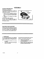
ENGINE
PREPARATION
Fill Crankcase
With
Oil
The trimmer was shipped with a container of
SAE30 motor oil. This oil must be added to the
engine before operating.
1, Remove the oil fill cap/dipstick shown in
Figure 4. Fill the crankcase to the FULL
line on oilfill cap/dipstick. DO NOT OVERFILL.
2. Install the oil fill cap/dipstick and tighten
securely.
Fuel Cap
Oil Fill Cap/
Dipstick
Fill Fuel Tank With Gasoline
For the correct procedure and grade of
gasoline, see "How To Fill With Gasoline" in
the Operation section.
ELECTRIC
Figure 4
START BATTERY
When the mower was shipped from the factory, the battery was not fully charged. Before the
first use, the battery must be charged for
16-24 hours. See "How To Charge The Battery" in the Service And Adjustment section.
_" CHECKLIST
For the best performance and satisfaction
from this quality product, please review the following checklist before you operate the trimmer:
As you learn how to use the trimmer, pay extra
attention to the following important items:
r_P "
Engine oil is at correct level.
P"
All assembly
completed.
been
J."_,_" Fuel tank is filled with fresh, clean, regular unleaded gasoline.
P",_" Become familiar and understand the
•_"
Check carton. Make sure no louse parts
remain in the carton.
function of all controls. Before your start
the engine, operate all controls.
712344
instructions
have
8
OPERATION
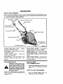
KNOW YOUR TRIMMER
READ THE OWNER'S MANUAL AND ALL SAFETY RULES BEFORE YOU OPERATE the trimmer, To familiarize yourself with the location of the controls, compare the illustrations with your trimmer. Save this manual for future reference,
Control Bail
Trimmer Head Drive Lever
Handle
Ignition Switch
Throttle Control Lever
Fuel Cap
Recoil Starter Handle
Engine Debris Shield
Handle Adjustment
Knob
Dipstick
Trimmer Head
Shield Edge Guard _"
Trimmer
Head Drive Lever
the rotation of the trimmer head.
Control
-
Figure5
Recoil
Engages
Control
Lever
-
Shield Edge Guard - Protects the shield
by automaticallycuttingthe line to the correct
length.
Controls the
Primer Button - Injects fuel directty into the
manifold for fester
- The engine is
Ignition Switch - Use on key-start engine.
speed or stops the engine.
carburetor
Handle
equippedwith an easy pull recoil starter.
Ball - Release to stop the rotation
of the trimmer head.
Throttle
Starter
starts.
Engine Debris Shield - Protects the engine from debris. Can be easily removed to
service the engine.
See
Figure 8.
EYE PROTECTION
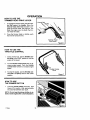
HOW TO STOP
THE TRIMMER HEAD
WARNING: Debris thrown from
the trimmer can resuR in foreign
1.
open position and disengage the trimmer
head,
eyes, which can cause severe
objects being thrown into the
eye damage. Always wear safety
glasses or eye shields when operating the trimmer.
Always wear safety glasses. If you wear eye
glasses, put a Wide Vision Safety Mask over
your eye glasses.
712344
Release tl_e control bell. It will return to its
HOW TO STOP THE ENGINE
1.
9
Move the throttle control lever
pletely back to the STOP position,
com-
OPERATION
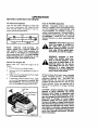
HOW TO USE THE
TRIMMER HEAD DRIVE LEVER
To engage the trimmer head, hold the control bail against the handle. Move the
trimmer head drive lever forward to en-
1.
gage the trimmer head. See Figure 6. The
faster the engine runs, the fester the trimmer head will rotate.
Once the trimmer head is rotating, push
the trimmerforward to trim.
2.
HOW TO USE THE
THROTTLE CONTROL
1.
During normal use, set the throttle control lever in the FAST position to run the
engine at full speed.
Pull the throttle control lever back to decrease engine speed. Push the throttle
control lever forward to increase engine
speed.
2,
Throttle Control
Lever
3. To stop the engine, pull the throttle control lever completely back to the STOP
position.
Figure 7
HOW TO USE
THE PRIMER BUTTON
1.
Push the primer button five times. See
Figure 8 for location. Wait approximately
two seconds between each push.
NOTE: Do not use the primer button to restart a warm engine after a short shutdown.
712344
10
OPERATION
BEFORE
STARTING
THE ENGINE
Oil Recommendation
How To Fill With Gasoline
Only use high quality detergent oil rated with
API service classification SG. Select the oil's
SAE viscosity grade according to your expected operating temperature:
NOTICE:
ENGINES WHICH ARE CERTIFIED TO COMPLY WITH CALIFORNIA AND
US EPA EMISSION
REGULATIONS
FOR
ULGE ENGINES:
Are certified to operate on
reguisr unleaded gasoline, include the following emission control system(s): EM, TWC (if
so equipped).
Include any user adjustable
features-therefore
no other adjustments are
needed.
I
Colder _,_
--
32OF
_I-_,b --_
I
Warmer I
<(--'---1---"-->>
=m,
5w30
f
I
'==' ==
SAE30
I
[
WARNING: Never fill the gas tank
hot. Allow the engine to cool
while the engine Is running or
before adding gasoline. Immediately wipe off any spilled gasoline before you start the engine.
NOTE:
Although
multi-viscosity
oils
(5W30, 10W30, etc.) improve starting in
cold weather, these multi-viscosity
oils
will result in increased
oll consumption
when used above 32°F. To avoid possible
engine damage from running low on oil,
frequently check your engine oil level.
Check
The
WARNING: Gasoline Is flammable. Usa caution when han-
Engine Oil
Before each use,
follows:
check
A
the engine
oi_ as
1.
Put the trimmer on a level surface.
2.
Remove the oil fill cap/dipstick shown in
Figure 9.
3.
Make sure the oil reaches the FULL mark
on the oil fill cap/dipstick.
4.
If necessary, add oil until the FULL mark
on the oil fill cap/dipstick is reached. DO
NOT OVERFILL. See "Oil Recommenda-
Fill the fuel tank with a fresh, clean, unleaded
regular, unleaded premium, or reformulated
automotive gasoline only.
DO NOT use
leaded gasoline. Be sure that the gasoline
container is clean and free from dust or other
foreign particles. Never use gasoline that is
stale from long periods of storage. Reinstall
fuel cap.
tion" for the grade and type of oil to use.
Fuel Cap
CAUTION: Alcohol blended fuels (called
gasohol or using methanol) can attract
moisture which leads to separation and
formation of acids during storage. Acidic
gas can damage the fuel system of an engine while in storage. To avoid engine
problems, empty the fuel system before
storage of 30 days or longer. Drain the fuel
tank. Start the engine and let it run until the
fuel lines and carburetor are empty. Never
usa engine or carburetor cleaner products
in the fuel tank or permanent damage may
occur. See "Storage Instructions" for additional information.
Oil Fill Cap/Dipstick
Debris Screen
Figure g
712344
away from an open flame or an
llng or storing gasoline. Keep
electrical spark. Do not smoke
while filling the fuel tank. Store
gasoline In a clean, approved
container In a cool well ventilated
place; never In the house.
11
OPERATION
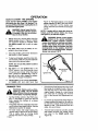
HOW TO START THE ENGINE
NOTE: DO NOT BE ALARMED, your engine
will smoke the first time it is started. It is
burning off the protective coating that is on
the internal engine parts.
mer unattended whil the engine
WARNING:
leave
trimis runngln. Never
Wait for
the the
trimmer
lines to stop rotation.
A
Before each use, remove debris from the
debris screen shown in Figure 9. Debris
can cause the engine to overheat. Wipe
the debris screen with a cloth or paper
towel.
2.
Key Start: Make sure the battery is connected to the wiring harness.
3.
Figure 10. Pull back sharply on the recoil
starter handle. DO NOT allow the starter
rope to snap back. Let the starter rope
slowly rewind as you hold the recoil starter
handle.
NOTE: If engine fails to start etter three attempts, push the primer button two times
and again try to start the engine.
indoors
or in
a poorly
ventilated
WARNING:
Never
run the
engine
area. Engine exhaust contains
carbon monoxide, an odorless and deadly gas. Keep hands, feet, hair and loose
clothing away from the trimmer and any
moving parts on the engine. Avoid the
muffler and surrounding areas. Temperatures may exceed 150°1=.
_k
Move the throttle control lever forward to
the START or FAST position.
To starta coldengine,pushthe primerbutton five times. Wait two seconds between
4,
each push of the primer button.
NOTE: Do not use the primer to start a
warm engine.
Key Start: Turn the ignition key to the
START position. Use short starting cycles
(15 seconds per minute). When the engine
starts, release the ignition key. If the engine will not turn over, charge the battery.
See "How To Charge The Battery".
5,
6.
Recoil-Start: Firmly hold the recoil starter handle with your right hand, See
TRIMMER
A
TIPS
gravel or rocks, can be thrown
WARNING:
Debris
such
as sticks,
with sufficient
force
to cause
personal injury or property damage.
Set the throttle control in the FAST position. If the weeds or grass are tall and
thick, operate the trimmer at a slower
walking speed.
Frequently clean the underside of the trimmer to remove any grass build up. See the
Maintenance section for details.
For best results and longer lasting line,
use the ends of the line to do the cutting.
This is easily done by moving slowly
through very thick or heavy weeds.
712344
12
Ignition Key
/
Figure 10
If the trimmer lines become too short, it will
take longer to complete the job. If the trimmer lines are worn to less than half their
original length, change to a new trimmer
line. "See How To Change The Trimmer
Line" in the Service And Adjustment section.
Do not trim on excessively steep slopes. If
a slope isdifficult to stand on, do not trim.
Do not trim on slopes when the ground is
slippery or wet. Trim across the face of a
slope, not up and down.
Trimmer head contact to concrete, asphalt
and harder services may create premature wear to the height guide (See
Figure 18).
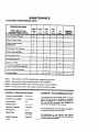
MAINTENANCE
CUSTOMER
RESPONSIBILITIES
SERVICE RECORDS
Before Every
Fill in dates as you
complete regular service.
:
Every
5
25
100
As
Use
Hours
Hours
Hours
Noted
:i:ilii
Check trimmertines
Every
Each
!! it ii ii i:!! !i:i:11:!i!i !i::i:ii:i_i:iI!:i:i:ii:iii:iii! :ii:i:]i:i_ii!ii:i:!:iii:_:: i:!:i:i:_
!!:!:!_:i:_
i:!:_:i:i:_
i:_!:!_:i:i
_i
,_/
1
; i
Engine/Machine Cleaning
SERVICE
DATES
!!
%/"
2
Check Spark Plug
"V"
:
:::::
:::;:,
::::::; :: :::::: :: :::
¢
Lubricate Wheel Bearings
Note I - When old line is half the original length, replace with new line.
Note 2 - Clean daily if used in extremely dusty or dirty conditions.
Note 3 - Change more often ff used in extremaly dusty or dirty conditions.
Note 4 - Charge battery before each season and before winter storage.
PRODUCT
SPECIFICATIONS
Trimmer Line Diameter
0,155 inch
Trimmer Line Length
21.5 inches
Horse Power
6.5
Displacement
12.0 cu, in.
Gasoline
1.5 quarts
Capaoity
Oil Capacity
20 oz.
Spark Plug
Champion
RJ-19LM
Spark Plug Gap
712344
GENERAL
RECOMMENDATIONS
The warranty on this trimmer does not cover
items that have been subjected to operator
abuse or negligence.To receive full value kom
the warranty, the operator must maintain the
trimmeras instructedin this manual.
Some adjustments must be made periodically
to properlymaintainyour trimmer.
All adjustments in the Service and Adjustmentssectionof this manual must be checked
at least once each season.
0,0,30 inch
13
MAINTENANCE
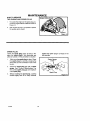
LUBRICATION
How To Lubricate
The Jackshaft Assembly
A grease fitting is provided to lubricate the
jackshaft assembly. Use a grease gun with automotive type grease to lubricate the jaskshatt
assembly as shown in Figure 11.
How To Change Engine Oil
Change the engine oil when the engine is
warm, Forthe properoilcapacity,see "Product
Specifications",
t.
Disconnectspark plugwire from the spark
plug.
2.
Remove the oil drain plug as shown in
Figure 12.
3.
Drain all the engine oil intoa fiat pan.
4.
Install the oil drain plug. Make sure the
oil drain plug is tight.
5.
Remove the dipstick.
6.
Fill the engine crankcase. DO NOT
OVERFILL. For proper oil capacity, see
"Product Specifications".
HOW TO REPLACE
THE AIR FILTER
5,
6.
Replace the air filter once a year or more often
in dusty or dirty conditions, DO NOT attempt to
clean or oil the air filter. Remove and install a
new air filter as follows:
Disconnect the spark plug wire from the
spark plug,
2.
Turn the cover clockwise as shown in
Figure 13. Remove the cover and the air
filter,
3.
Discard the old air filter.
4. Clean the cover and the flange.
712344
Put the new air filter into the cover.
Push the cover firmly against the flange.
Turn the cover counterclockwise until
tight. Be sure the retainers
around the flange.
CAUTION: Never run the engine without
the air filter installed. An air filter clogged
with dust can result in loss of engine power
and can cause excessive wear or damage
to the engine. If the air filter Is clogged, replace Immediately.
1.
Cohnect the spark plug wire to the spark
plug.
7,
7,
14
are locked
Connect the spark plug wire to the spark
plug.
MAINTENANCE
HOW TO SERVICE
THE ENGINE AND SPARK PLUG
1.
To access the engine or the spark plug, remove the engine debris shield as shown in
Figure 14.
2.
After engine service is completed,
the engine debris shield.
replace
SPARKPLUG
Check the spark plug every 25 hours. Replace the spark plug if the electrodes are
pitted or burned or if the porcelain is cracked.
Tighten the spark plug to a torque of 15
foot-pounds.
Make sure the spark plug is clean. Clean
the spark plug by carefully scraping the
electrodes (do not sand blast or use a wire
brush).
1,
Check the spark plug gap with a feeler
gauge. See "Product Specifications"for
the correct spark plug gap and replacement spark plug.
2.
3.
Before installingthe spark plug, coat the
threads lightlywith oil for easy removal.
712344
15
SERVICE AND ADJUSTMENT
SERVICE
AND ADJUSTMENT
Make sure that
all moving
parts clean
have or
stopped.
wire
the
WARNING:
Before
you inspect,
service Disconnect
the trimmer, the
stop
thefrom
engine.
spark plug.
_h)
HOW TO
REPLACE
THE TRIMMER
LINE
For the best performance, use a heavy
gauge (0.155" diameter) trimmer line. Cut
the length of the trimmer line to 21.5 inches.
Use the length guide, located on the shield,
to make sure the trimmer line is the correct
length. See Figure 16, Do not allow the
length of the lines to vary more than one
inch. This is important to make sure the trimmer head is balanced and does not vibrate.
IMPORTANT: To extend the life of the trimmer line, keep the trimmer line moist, if not
kept moist, the nylon trimmer line will become dry and brittle. Keep extra trimmer
line In a can of water. The line will then stay
flexible and easy to change. A flexible line
will also last much longer.
HOW TO CHANGE
TRIMMER
LINES
When the trimmer line becomes worn to half the original length, replace the trimmer line as
follows:
Une
Retainer
Trimmer
Line
1.
Stop the engine. Wait for
all moving parts to stop.
2.
Remove worn trimmer
line from line retainer,
3,
Une
Retainer
4.
Next, take the ends of the
tine. cross over the line
retainer, and thread the
ends through the center
hole.
First, thread the ends of
the new trimmer
line
through
the
outside
loops.
712344
16
5.
Then, check to make
sure that the ends of the
line are even.
SERVICE
AND ADJUSTMENT
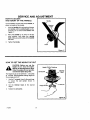
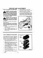
HOW TO ADJUST
THE HEIGHT OF THE HANDLE
I
Handle
Use the knoba, on each side of the handle, to
adjust the height of the handle.
1.
I
I
Ratchet
Teeth
Hold the handle with one hand and loosen
both knobs until the ratchet teeth are disengaged. Do not remove the knobs. See
Figure 17.
2.
Move the handle up or down to the desired position, then align the ratchet
teeth. Make sure both sides of the handle
are level.
3.
Tighten the knobs.
HOW TO SET THE HEIGHT
OF CUT
CAUTION: Before you set the
height of cut: stop the engine.
Wait for all moving parts to stop.
Allow the engine to cool and disconnect the spark plug wire.
Height Of
Set Screw
Trimmer
Head
The height of cut can be set from 1-1/'2 inches
to 3 inches. Recommended cutting height for
the average yard is 2".
1,
Use the T-wrench, found in the parts bag,
to loosen the set screw
shown in
Figure 18,
2.
Set
the trimmer
head
at the
desired
Height Guide
height.
3.
Tighten the set screw.
.__t;
Rgure 18
712344
17
SERVICE AND ADJUSTMENT
HOW TO
REPLACE
THE DRIVE BELT
To replace the drive belt, the trimmer head
and shield must be removed as follows.
the drive belt, disconnect the wire
WARNING:
Before you remove
from the spark plug.
_lb
1.
Remove the two fasteners
that hold the
rear of the shield to the trimmer
(See Figure lg).
housing
2.
Remove the four fasteners that hold the
front of the shield and trimmer head to
the trimmer housing,
3.
Remove
bracket.
the
"V"
pulley from
the
idler
Raise the front of the trimmer housing
and remove the drive belt. On some models, it is necessary to loosen the mounting bolt forthe drive pulley to remove the
drive belt (see Figure20). Do not bend the
belt guides.
4.
NOTE: Make sure you replace the drive
belt only with a replacement belt from
the factory.
To assemble the drive belt, reverse the
above steps, Make sure all fasteners are
tight. Make sure the mounting bolt for the
drive pulley Is tight.
5.
6.
Drive Belt -
Check the routing of the drive belt. Make
sure the drive belt is inside of all belt
guides shown in Figure 20.
Belt
IMPORTANT: Test the drive system. Start
the engine and move the throttle control to
the FAST position. Engage and disengage
the trimmer head several times. When disengaged, make sure the trimmer head completely stops when resting on the ground. If
the trimmer head continues to rotate, take
the trimmer to the nearest Craftsman
Service Center.
712B44
e .Pulley
18
Figure 20
SERVICE AND ADJUSTMENT
HOWTO
CHARGE
THE BATTERY
sulfuric acid which is harmful to
WARNING:
The battery contains
kthe skin, eyes and clothing. If acid
gets on the body or clothing, wash with
water. Do not attempt to open the battery.
If the battery has a crack, replace the battery. Do not burn a damaged or old battery
or an explosion
can result.
_
3
Chargethebatteryfor16-24 hours.
4.
Disconnect the battery charger from the
electrical outlet and from the battery.
5.
Connect the wiring harness to the battery. If the battery will not be used for a long
period of time or during storage, do not
connect the wiring harness to the battery.
A
WARNING: When you charge the
battery, do not smoke. Keep the
battery away from any sparks.
The fumes from the battery acid can cause
an explosion.
The battery is in the battery case mounted under the rear frame.
IMPORTANT: Make sure to use the battery
charger supplied with the mower. The use
of any other battery charger will damage
the battery.
1.
Disconnect the wiring
battery (Figure 21).
2.
Attach the battery charger wire to the
battery. Connect the battery charger to an
electrical outlet.
HOW TO REMOVE
harness
from the
THE BATTERY
If the engine will not turn over or turns over
slowly when the key is turned on, charge the
battery. See "How To Charge The Battery". (f
the battery will not charge fully and will not start
the engine, replace the battery as follows.
1.
Disconnect the wiring harness
battery (Figure 21).
2.
Remove the two screws
Battery
from the
Battery
that secure the
battery caseto the frame (Figure 2 t). Remove the battery case from the frame.
3.
To open the battery case, remove the two
screws (Figure 22), Remove the battery
from the battery case.
4.
Replace the battery with an authorized
factory replacement battery.
5.
Charge the new battery for 15 hours. See
"How To Charge The Battery".
6.
To install the battery,
steps.
712344
reverse
Battery
Figure 22
the above
19
SERVICE
AND ADJUSTMENT
STORAGE
WARNING: Do not remove gasoline while Inside a building, near
a fire, or while you smoke. Gasoline fumes can cause an explosion or a fire.
To prevent engine damage when the trimmer
is in storage for 30 days or more, follow the
steps below:
Let the engine run until it is out of gasoline.
Drain the oil from the warm engine. Fill the
engine crankcase with new oil.
When the trimmer is put in storage for thirty
days or more, follow the steps below to
make sure the trimmer is in good condition
the following season.
'o
Trimmer
Remove the spark plug from the cylinder,
Pour one ounce of oil into the cylinder.
Slowly pull the recoil starter handle so that
the oilwill protect the cylinder. Install a new
spark plug in the cylinder.
Completely clean the trimmer.
Clean dirt and debris from the cylinder
cooling fins and the engine housing.
Put the trimmer in a building that has good
ventilation.
If you do not want to remove gasoline, add
a fuel stabilizer, such as Craftsman fuel
stabilizer No. 33500, to any gasoline left in
the tank. Craftsman
fuel stalibizer will
NOTE:
A yearly checkup or tune-up at a
Craftsman authorized service
center will
make sure that the trimmer will provide
maximum
performance
for the next season.
minimize the formation of gum deposits
and acids. If the tank is almost empty, mix
Craftsman fuel stabilizer with fresh gasoline in a separate container and add the
mixture to the tank. Always follow the instructions on the stabilizer container. Run
the engine at least ten minutes after stabilizer is added to allow the mixture to reach
the carburetor.
Engine
IMPORTANT: It is important to prevent gum
deposits from forming in fuel system parts
such as the carburetor, fuel filter, fuel hose,
and tank during storage. Also, using alcohol-blended fuels (called gaeohol, ethanol
or methanol) can attract moisture which
leads to separation and formation of acids
during storage. Acidic gas can damage the
fuel system of an engine while in storage.
712344
Battery
Charge the battery for 16-24 hours before
storage and again before use each season.
20
TROUBLE SHOOTING CHART
TROUBLE
CAUSE
CORRECTION
Engine does not start
Spark plug wire
disconnected.
Connectspark plugwire.
Engine not primed.
Prime engine.
Defective or incorrectly
gapped spark plug.
Inspect or replace spark
:)lug.
Fuel tank empty.
Add fuel.
Dirty carburetor or fuel line.
Clean carburetor or fuel line.
Dirty air filter.
Replace air filter.
Carburetor out of adjustment.
For carburetoradjustment,
take the unitto a Craftsman
Service Center,
Engine flooded.
Wait several minutasbefore
starting.
: Throttle control laver in
incorrect position.
Engine runs poorly.
Aove throttlelever to FAST
or START position,
Stale gasoline.
Drain old gasolineand add
fresh gasoline.
Defective throttle control
lever or wire.
Inspectlever and wire.
Replace if damaged or
dafec[_ve.
Battery
isnot fully charged.
Charge battery 16-24 hours,
Wiring harness not
connected to battery.
Connect wiringharness.
Bad spark plug.
Replacespark plug.
Dirty air filter.
Replace air filter.
Carburetorout of adjustment. ! Adjust carburetor.Take the
unitto a CraftsmanService
Center.
712344
Stale gasoline.
Drain old gasoline.Add fresh
,gasoline.
Engine coolingsystem
clogged,
Clean engine screen and
coolingfins.
21
TROUBLE SHOOTING CHART
Engine overheats.
Engi.newill not stop
runn,ng.
Poor trimming
performance.
Engine cooling system
clogged.
Clean debris screen and
engine cooling fins.
Carburetor
Adjust carburetor. Take the
unit to a Craftsman Service
Center.
out of adjustment.
Oil level is low.
Add oil.
Defective throttle control
lever or wire.
Inspect and replace
damaged parts.
Throttle not adjusted
properly.
Move throttle to the full OFF
position.
Trimmer line length is too
short.
Correct line length is 21.5
inches. When less than 1/2
this length, replace the line.
i Engine not set at FAST
speed.
Trimmer vibrates,
Trimmer head does not
retain line
Set screw for trimmer head
is loose.
Tighten set screw with
T-handle wrench.
Trimmer line lengths are
substantially different.
Adjust trimmer line to
approximately equal lengths.
Loose nuts or bolts.
Check all bolts and nuts,
including engine bolts.
Broken trimmer head.
Replace broken part.
Trimmer line not properly
attached.
Follow instructions on decal
or in the Service section of
the owner's manual.
Broken line retainer.
Trimmer line not correctsize.
712344
Move engine throttle lever to
FAST position.
22
I Replace trimmer head
assembly.
Use Craftsman 0.155 inch
diameter trimmer line.
•
-
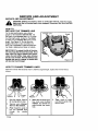
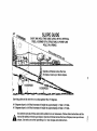
SLOPE GUIDE
i""u-._.Q...REE_
,i
_
i,:
SIGHT AND HOLD THIS GUIDE
" ...... :............
TREE, A CORNER
I ..................
J
-:,
LEVEL WITH A VERTICAL
OF A STRUCTURE,
A POWER
LINE
POLE, OR A FENCE.
........
_= I
m°eaeeJ°eeeoo.e.e,
I
Operate a trimmer across the face
of slopes, never up or down slopes.
I
I
I
0_
oJ
10 DEGREES
15 DEGREES
Use this guide and do not trim on a slope greater
than 15 degrees.
A 10 degree slope is a hill that increases
A 15 degree slope is a hill that increases
at approximately
at approximately
Use extreme
_
in height
in height
care at all times
and avoid
sudden
turns
anual for safety in trimming
slopes.
Use extra care when
on slopes.
operating
Operate a trimmer
on or near slopes
1.7 feet in 10 feet..
2.5 feet in 10 feet..
or maneuvers.
Follow
other
across the face of slopes,
and obstructions.
instructions
in this
never up or down
03
F-
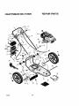
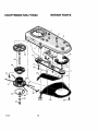
CRAFTSMAN
REPAIR PARTS
536.773520
1
\
10
11
12
14
27
\
18
12
20,
21
24
30
39
31
27
33
712344
34
36
24
\
37
CRAFTSMAN
536.773520
Key
No.
712344
REPAIR
Description
Part No.
1
2
Handle Assy,
Lever, Control
740198-846
3
Bolt
323035
4
8
Strap, Tie
Washer
712267
17x38 Z
7
Guide, Rope
672510
8
Cable, Control Latching
740193
9
Key, Ignition
740228
10
Cable, Throttle w/ES
740225
11
Bolt
323034
12
Screw
710269
13
Cover, Battery
740218
14
Harness, Wiring
740221
15
Battery
740220
16
Holder, Battery
740222
17
Case, Battery
740219
18
19
Charger, Battery
Knob, Handle
740223
20
21
Washer, Spring
PLvot, Handle
711936
22
Bolt
711937
23
Handle, Lower
740195-846
24
Screw
710079
25
143.998512,
26
27
Harness Clamp
Nut
740217
28
Wheel and Tire
740185
29
Washer
710258
30
Spacer
740190
31
Bracket Assembly, Axle and
740188
32
33
Bolt, Carriage
Bolt
711935
34
Nut
35
Nut
710203
710205
36
37
Shield, Trailing
Bolt
740192
38
Frame
39
40
Glasses, Safety
Decal
740216-848
711890
41
Spacer, PM .26x.5x.2
672292
42
Washer, Formed
783000
740198-848
740202
740158
See Engine Pages
ENGINE
710140
48901
710265
712030
25
PARTS
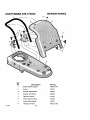
CRAFTSMAN
REPAIR PARTS
536.773520
1
2
3
,8
15
25..
26
\
2O
27
\
31
31
38
23
712344
26
CRAFTSMAN
Key
No.
712344
REPAIR PARTS
536.773520
Description
Pa_ No.
1
Nut
710140
2
Bolt
711978
3
Frame
740216-848
4
Screw
710272
5
Idler Assembly
740232
6
Bolt
710200
7
Spring
712403
8
Spacer, Jackshaft Housing
740292
9
Nut
712148
10
Washer
710083
11
Pulley, Cutting Head
740171
12
Spacer
740173
13
Belt
711933
14
Pulley, Idler
740244
15
Pulley, Engine
740179
16
Pulley, Idler
740183
17
Lockwasher
712147
18
Bolt
712146
19
Screw
712145
20
Rap, Debris
740167
22
Guard Assy,
770070
23
Screw
710269
24
Jackshaft Housing Assembly
092574
25
Shaft, Cutting Head
740246
26
Wrap, Upper Head
740163
27
Screw
712126
29
Cutting Disc Assembly
740175-848
30
Screw, Set
712127
31
Une, (Cutting Pack of 24)
79999
32
Flatwasher
712440
33
Guide, Height
740226
36
Lockwasher
120380
37
Bolt
180018
38
T-Wrench
712128
27
CRAFTSMAN
REPAIR PARTS
536.773520
5 .......Q
5
/
3
Key
No.
712344
Description
Part No.
1
Engine Debris Support
740234-846
2
Screw
710273
3
Bracket, Right Shield
740238
4
Bracket, Left Shield
740245
5
Ratchet Fastener
311087
6
Shield, Engine Debris
740229
7 •
Knob, Debris Shield
740227
8
Housing, Trimmer
740216-848
28
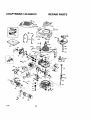
CRAFTSMAN
143.996512
REPAIR PARTS
370E
goo
400
135
130
126
120
416
119
125
_310
46
"3O5
"_ _'_
245
238
712344
250
29
• 306
CRAFTSMAN
KEY
NO.
PART
NO.
REPAIR PARTS
143.996512
KEY
NO.
DESCRIPTION
PART
NO.
DESCRIPTION
0
RPM High 3450 to 3750
52
29914
Oil Pump Ass'y.
0
RPM Low 2000 to 2300
69
35261
Mounting Range Gasket
70
34311E
Mounting Range
(Incl. 72 thru 83,306)
72
36083
Oil Drain Plug
1
37266
Cylinder (IncL 2,20 & 150)
2
26727
Dowel Pin
6
33734
Breather Element
75
27897
Oil Seal
7
36557
Breather Ass'y.
(Incl. 6 & 12A)
80
30574A
Governor Shaft
12
36775
Breather Tube
81
30590A
Washer
12A
36558
Breather Cover & Tube
(Incl. 12B)
82
30591
Governor Gear Ass'y.
(Incl. 81)
12B
36694
Breather Tube Elbow
83
30588A
Governor Spool
14
28277
Washer
86
650488
Screw, 1/4-20 x 1-1/4"
15
30589
Governor
Rod (Incl. 14)
89
610961
Rywheel Key
16
34839A
Governor
Lever
90
611179
Flywheel
17
31335
Governor Lever Clamp
92
850815
Belleville Washer
18
651018
Screw, Torx T-15,
8-32 x 19/64"
93
650816
Flywheel Nut
lOO
34443B
Solid State Ignition
19
37329
Extension Spring
lOl
610118
Spark Plug Cover
20
32600
Oil Seal
lO3
651007
30
34570A
Crankshaft
Screw, Torx T-15,
10-24 x 15/16"
40
40027
Piston, Pin & Ring Set
(Std.)
11o
36230
Ground Wire
110A
34970
Ground Wire
40
40028
Piston, Pin & Ring Set
(.010" OS)
tlOC
35020
Ground Wire
41
40025
Piston & Pin Ass'y.
(Std.) (Incl. 43)
119
36787
Cylinder Head Gasket
120
36825
Cylinder Head
41
40026
Piston & Pin Ass'y.
(.010" OS) (Incl. 43)
125
37288
Exhaust Valve (Std.)
(Incl. 151)
42
40006
Ring Set (Std.)
126
37289
42
40007
Ring Set (.010" OS)
Intake Valve (Std.)
(Incl. 151)
43
20381
Piston Pin Retaining Ring
130
6021A
Screw, 5/16-18
45
36777
Connecting
(Incl. 46)
135
35395
Resistor Spark Plug
(RJ19LM)
46
32610A
Connecting Rod Bolt
150
31672
Valve Spring
48
27241
Valve Lifter
151
31673
Valve Spring Cap
50
36778
Camshaft
151A
40017
Intake Valve Seal
712344
Rod Ass'y.
(MCR)
30
x 1-1/2"
CRAFTSMAN
REPAIR PARTS
143.996512
169
36783
Valve Cover Gasket
301
36246
Fuel Cap
172
36784
Valve Cover
305
35647
Oil Fill Tube
174
30200
Screw, 10-24 x 9/16"
306
36996
"O'-Ring
178
29752
Nut & Lock Washer,
1/4-28
307
35499
"O"-Ring
309
650562
Screw, 10-32 x 3/8"
179
30593
Retainer Clip
310
35648
Dipstick
182
6201
Screw, 1/4-28 x 7/8"
313
34080
Spacer
184
26756
Carburetor
Gasket
314
650767
Screw, 8-32 x 27/64"
To Intake Pipe
185
36785
Intake Pipe
315
34990
Alternator
Coil
186
36255
Governor
322
35013
Connector
Body
189
650831
Screw. 1/4-20 x 1/2"
324
33177
Terminal
200
37134
Control Bracket (Incl. 206)
325
37152
Spring Clip
206
610973
Terminal
347
651038
Screw, 10-32 x 27/32"
207
36200A
Throttle Link
370A
36261
Lubrication Decal
209
30200
Screw, 10-24x9/16"
370C
37199
Primer Decal
223
650451
Screw, 1/4-20 x 1"
370E
34387
Air Cleaner Decal
224
36786
Intake Pipe Gasket
380
640069
Carburetor
238
650932
Screw, 10-32 x 49/64"
390
590739
Rewind Starter
239
34338
Air Cleaner Gasket
241
36919
Air Cleaner Collar
245
36905
Air Cleaner Filter
250
36920
Air Cleaner Cover
260
36980
Blower Housing
261
30200
Screw, 10-24 x 9/16"
262
650831
Screw, 1/4-20
263A
37198
Starter Grill
275
36790A
Muffler
277
650988
Screw, 1/4-20
285
35000A
Starter Cup
287
650926
Screw, 8-32 x 21/64"
290
29774
Unk
(Incl, 184)
(NOTE: This engine could
have been built with
590702 starter).
395
35707
Electric Starter Motor
(12 Volt)
400
36792B
Gasket Set (incl. Items
Marked PK in Notes)
Incl. Part #'s 26756 (1),
28833 (1), 34338 (1),
36783 (1), 36786 (1),
36787 (1), 36832 (1),
36996 (1), 37130 (1).
x 1/2"
416
36085
Spark Arrestor Kit
(Incl. 417) (Optional)
417
650821
Screw. 10-32 x 1/2"
(Optional)
Fuel Line
900
0
Replacement Engine
NONE, order from 71-999
900
0
x2-9/32"
292
26460
Fuel Une Clamp
298
28763
Screw, 10-32 x 35/64"
Replacement Short Block
750812B,
300
36916
Fuel Tank (Incl. 292 & 301)
order from 71-999
712344
31
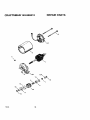
CRAFTSMAN
REPAIR PARTS
143.996512
27
_m37
_36
(_37
4O
712344
32
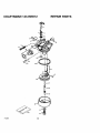
CRAFTSMAN
712344
REPAIR PARTS
143.996512
KEY
NO.
PART
NO.
0
640069
Carburetor
(Incl. 184 of Engine Parts !ist
1
631615
ThrottleShaft & Lever Assembly
2
631767
Throttle Return Spring
4
631184
Dust Seal Washer
5
631183
Dust Seal (Throttle)
6
640070
ThrottleShutter
7
650506
Shutter Screw
16
631807
Fuel Fitting
17
651025
Throttle Crack Screw / Idle Speed
18
630768
TensionSpring
20
640027
Idle RestrictorScrew
20A
640053
Idle RestrictorScrew Cap
25
631867
Float Bowl
27
631024
Float Shaft
28
632019
Float
29
631028
Float Bowl "O" Ring
30
631021
Inlet Needle, Seat, & Clip (Incl. 31)
31
631022
Spring Clip
35
36045A
Primer Bulb/RetainerRing
36
632735
Main Nozzle Tube
37
632547
"O" Ring, Main Nozzle Tube
40
840030
High Speed Bowl Nut
44
27110A
Bowl Nut Washer
47
630748
Welch Plug, Idle Mixtur# Well
48
631027
Welch Plug, AtmosphericVent
60
632760
Repair kit
(Incl. Items Marked PK in Notes)
DESCRiPTiON
33
CRAFTSMAN
REPAIR PARTS
143.996512
11c
8
6
\
712344
34
CRAFTSMAN
712344
REPAIR PARTS
143.996512
KEY
NO.
PART
NO.
0
35707
Electric Starter (12 Volt)
1
34955
Retainer Ring
2
34950
Spring Retainer
3
34954
Spring
4A
34949A
Gear
5B
34953
Drive End Cap Ass'y,
6
33450
Lock Nut
7
34944
Armature
8
34945
Housing Ass'y.
10A
590500
Thrust Washer
tlC
34942
Commutator End Cap Ass'y. (Incl. brushes)
12
34947
Bolt, 10-32 x 3-3/15"
13
34946
Pinion Driver
14
34951
Cup Washer
15
34952
Retainer Ring
16
34948
Washer
17
34953
Drive Nut
18
590608
Washer
DESCRIPTION
85
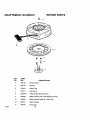
CRAFTSMAN
REPAIR PARTS
143.996512
V--14
11
12
13
j
712344
I
-7
KEY
NO.
PART
NO.
0
590739
Rewind Starter
3
590740
Retainer
6
590616
Starter Dog
7
590517
Dog Spring
8
590618A
Pulley & Rewind Spring As$'y
11
590638
Starter Housing Ass'y (40 degree grommet)
12
590535
Starter Rope (Length 98" x 9/64" dia.)
13
59070 t
Starter Handle
14
59O760
Spring Clip
DESCRIPTION
36
NOTES
712344
37
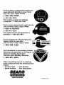
For the repair or replacement
parts you
need delivered directly to your home
Call 7am-7pm,,,7days
a week
1-800-366-PART
(1-800-366-7278)
Para ordenar piezas con entrega
a domicilio - 1-800-659-7084
For in-house major brand repair service
Call 24 hours a day, 7days a week
1-800-4-REPAIR
(1-800-473-7247)
Para pedir servicio de reparacibn
domicilio1-800-676-5811
a
For the location of a Sears Parts and
Repair Center in your area
Call 24 hours a day, 7days a week
|g|ggg
1-800-488-1222
For information on purchasing a Sears
Maintenance agreement or to inquire
about an existing Agreement
Call 9am-5pm, Monday-Saturday
1-800-827-6655
When requesting service or ordering
parts, always provide the following information:
• Product Type
• Model Number
• Part Number
• Part Description
8B,AR8
America's
Repair
Specialists
Printed in U.S.A.