1
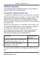
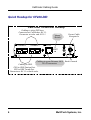
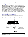
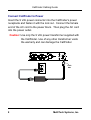
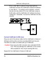
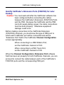
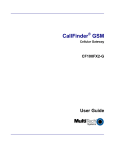
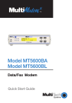
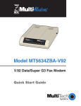
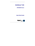
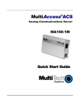
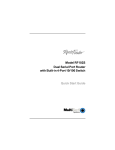
CallFinder® DID
DID-to-Analog Adapter
Model CF220-DID
Cabling Guide
CallFinder DID Cabling Guide
Model CF220-DID
82100292L
Copyright © 2008 by Multi-Tech Systems, Inc.
All rights reserved. This publication may not be reproduced, in whole or in part,
without prior expressed written permission from Multi-Tech Systems, Inc.
Multi-Tech Systems, Inc. makes no representation or warranties with respect to
the contents hereof and specifically disclaims any implied warranties of
merchantability or fitness for any particular purpose. Furthermore, Multi-Tech
Systems, Inc. reserves the right to revise this publication and to make changes
from time to time in the content hereof without obligation of Multi-Tech Systems,
Inc., to notify any person or organization of such revisions or changes. Check
Multi-Tech’s web site for current versions of our product documentation.
Record of Revisions
Revision
A
B
C
Date
06/15/07
10/02/07
03/14/08
Description
Initial release of CF220-DID Cabling Guide.
Update support info and fix format.
Update mechanical drawing.
Trademarks
CallFinder, FaxFinder, Multi-Tech, and the Multi-Tech logo are registered
trademarks of Multi-Tech Systems, Inc. All other brand and product names
mentioned in this publication are trademarks or registered trademarks of their
respective companies.
Multi-Tech
Systems, Inc.
2205 Woodale Dr.
Mounds View, MN
55112, USA
(763) 785-3500
(800) 328-9717
Fax: 763-785-9874
www.multitech.com
2
TECHNICAL SUPPORT
Country
By E-mail
By Phone
Europe,
Middle East, [email protected] (+44)118 959 7774
Africa
U.S.,
Canada,
All Others
[email protected]
(800) 972-2439;
(763) 717-5863
MultiTech Systems, Inc.
CallFinder Cabling Guide
Introduction
This guide describes the hardware setup of the CF220-DID
CallFinder unit, and some preliminary considerations for its interoperation with PBX units. Instructions for software setup can be
found in the User Guide.
Mechanical Mounting
The CF220-DID CallFinder can be surface mounted with screws
spaced according to the dimensions shown.
MultiTech Systems, Inc.
3
CallFinder Cabling Guide
We Supply
• A CallFinder (CF220-DID) with factory-installed software
• A two-piece 9 Vdc power supply with power cord
• Four common telephone cables (1 for each port; RJ-11 at
both ends)
• A product CD that contains: (a) a system management
software package for the administrator’s PC, and (b)
additional documentation for administrators
• This printed Cabling Guide
You Supply
• A nearby AC power outlet
• Two nearby connections to a PBX or key phone system
• One or two nearby analog DID trunk lines each with a block of
associated DID telephone numbers
• A connection to your Ethernet LAN
• A PC with an Ethernet connection and a web browser from
which to configure the CallFinder unit. (Windows or Linux can
be used to access the CallFinder software. Windows NT,
Windows 2000, or Windows XP is required to access the
Device Manager software.)
4
MultiTech Systems, Inc.
CallFinder Cabling Guide
CallFinder Operation
The CallFinder brings analog DID services to a key telephone
system or PBX that is not DID-enabled.
Prerequisite: Ordering the DID Lines
To operate the CallFinder system, you will need one or two DID
(Direct Inward Dial) lines in your office. You must order the DID
lines from your local telephone operating company (telco). A
DID line allows one phone line to be associated with multiple
directory numbers. However, only one call can occur on this line
at any given time.
DID lines are sold in groups. For example, a telco in New York
City might offer a DID line with a set of 10 directory numbers in
the range of 212-555-4100 through 212-555-4109.
When ordering your DID line, ask the telco representative for
these details about the DID service. These details will be
important when setting up your CF220-DID unit.
Parameter
Value Required
by Telco
Number of digits used to designate the
DID extension (usually 3, 4, 6, or 7)
Type of “DID Start” used (wink,
immediate, or delay dial)
You will need this information to configure your CallFinder unit
later.
MultiTech Systems, Inc.
5
CallFinder Cabling Guide
Quick Hookup for CF220-DID
CallFinder CF220-DID Hookup
Cabling to telco DID lines.
Connector at CallFinder: RJ-11.
Connector at telco end: RJ-11.
CHANNEL 2
CHANNEL 1
Reset
Switch
Power Cable
Receptacle
10/100
RESET
FXS/FXO
DID
FXS/FXO
DID
To
Cabling to your Ethernet LAN. Earth Ground
RJ-45 connector.
Cabling to PBX.
FXO to PBX Station Port.
FXS to PBX Trunk Port.
Connectors: RJ-11 at both ends.
6
MultiTech Systems, Inc.
CallFinder Cabling Guide
Cabling Instructions
Summary: Place the CallFinder in a convenient location, and
then connect it to earth ground, to your AC power outlet, to your
Ethernet network, and to your telco DID service. You cannot
connect the CallFinder's Extension Ports (FXS/FXO) to your
PBX until after you have configured the CallFinder software. In
the CallFinder software, you will configure the Extension Ports
as either FXS or FXO, and this must be done before they can be
connected to your PBX.
Connect CallFinder to Earth Ground
Connect the CallFinder’s ground connector to a true earth
ground (the ground of your building’s electrical system).
Product
Ground
Screw
Ground Wire:
Size 18AWG
or thicker
Earth Ground Screw:
Connected to
Permanent Earth Ground
of Building’s
Electrical System
Grounding connectors
must be secured
permanently to
product ground screw
and earth ground screw.
GND
MultiTech Systems, Inc.
7
CallFinder Cabling Guide
Connect CallFinder to Power
Insert the 9 Vdc power connector into the CallFinder’s power
receptacle and fasten it with the lock nut. Connect the female
end of the AC cord to the power block. Then plug the AC cord
into the power outlet.
Caution: Use only the 9 Vdc power transformer supplied with
the CallFinder. Use of any other transformer voids
the warranty and can damage the CallFinder.
Lock
Nut
8
MultiTech Systems, Inc.
CallFinder Cabling Guide
Verify powering.
After power is applied, the PWR LED comes on immediately but
there is a 4-second delay before the Status LED comes on. In
normal operation, the Status LED will be flashing.
When you apply power, the CallFinder performs a diagnostic
self-test. The Status indicator flashes when the embedded
processor is up and running. If the Status indicator does not
flash, check that the power supply is solidly connected and that
the AC outlet is live.
Connect CallFinder to Ethernet Network
Plug one end of your RJ45 Ethernet cable into the CallFinder’s
Ethernet jack (labeled “10/100”) and the other end into your
network Ethernet hub. This Ethernet cable is not included with
your CallFinder unit.
Note: Before connecting to the Ethernet Network, make sure
that the network to which you are connecting the
CallFinder is not a 192.168.2.x subnet.
MultiTech Systems, Inc.
9
CallFinder Cabling Guide
If it is a 192.168.2.x subnet, it may clash with the
CallFinder because the CallFinder’s default IP address
is 192.168.2.1. To remedy such a situation, connect
directly from the Admin PC to the CallFinder using an
RJ45 cable until the CallFinder’s IP address has been
configured. Thereafter, connect the CallFinder into the
network.
Connect CallFinder to DID Lines
Plug one end of the phone cable into the CallFinder’s Channel 1
DID jack and the other end into an analog DID trunk line jack.
The DID Line cable is included with your CallFinder.
Caution: Never plug the DID connector into a standard POTS
Line. This may damage the CallFinder or the central
office equipment. Use only an analog DID Line.
Repeat for the CallFinder’s Channel 2 DID port.
10
MultiTech Systems, Inc.
CallFinder Cabling Guide
Identify CallFinder’s Extension Ports (FXS/FXO) for Later
Hookup
Caution: You must wait until after the CallFinder software has
been configured before connecting the cables
between the CallFinder’s Extension (FXS/FXO) Ports
and the PBX. Because the CallFinder and the PBX
can both supply battery power, the cable connections
must be done properly. Otherwise equipment
damage could occur.
Before making connections to the CallFinder Extension
(FXS/FXO) channels, you must know the type of PBX port to
which each CallFinder port will be connected and set the
“Extension Port” field in the CallFinder Channel Configuration
screen appropriately.
When connecting to a PBX Station Port,
set the CallFinder channel to FXO.
When connecting to a PBX Trunk Port,
set the CallFinder channel to FXS.
When the Channel Configuration | Extension Port software
field has been set properly for both CallFinder channels, you can
proceed to connect the cable between each of the CallFinder’s
FXS/FXO ports and the corresponding PBX port.
MultiTech Systems, Inc.
11
Patents
This device is covered by one or more of the following patents: 6,031,867;
6,012,113; 6,009,082; 5,905,794; 5,864,560; 5,815,567; 5,815,503; 5,812,534;
5,809,068; 5,790,532; 5,764,628; 5,764,627; 5,754,589; D394,250; 5,724,356;
5,673,268; 5,673,257; 5,644,594; 5,628,030; 5,619,508; 5,617,423; 5,600,649;
5,592,586; 5,577,041; 5,574,725; D374,222; 5,559,793; 5,546,448; 5,546,395;
5,535,204; 5,500,859; 5,471,470; 5,463,616; 5,453,986; 5,452,289; 5,450,425;
D361,764; D355,658; D355,653; D353,598; D353,144; 5,355,365; 5,309,562;
5,301,274. Other patents pending.
82100292L