1
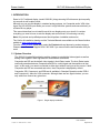
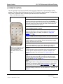
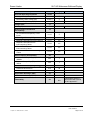
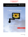
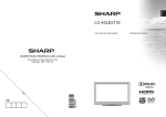
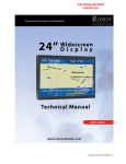
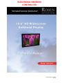
ELECTRONIC REVISION CONTROLLED Document Number 106282 Rev D Rosen Aviation 10.6” HD Widescreen Bulkhead Display Technical Manual, 10.6” HD Widescreen Bulkhead Display © 2013 by Rosen Aviation, LLC All Rights Reserved The information contained herein is proprietary to Rosen Aviation, LLC. No part of this publication may be reproduced, transmitted, transcribed, stored in a retrieval system, or translated into any language in any form by any means without the written authorization from Rosen Aviation, LLC, except as allowed under copyright laws. Disclaimer of Liability The information contained in this document is subject to change without notice. Because we are continuously improving and adding features to our products, Rosen Aviation, LLC reserves the right to change specifications without prior notice. Rosen Aviation, LLC shall not be liable for technical or editorial errors or omissions contained herein. Rosen Aviation, LLC 1020 Owen Loop South Eugene, OR 97402 541.342.3802 888.668.4955 Fax: 541.342.4912 www.rosenaviation.com Document Number: 106282 Template: 4.4.1.6FM2; Revision A; 12/06/12 Revision: Date: 03/20/14 D Page 2 of 30 Rosen Aviation 10.6” HD Widescreen Bulkhead Display Contents 1. INTRODUCTION .................................................................................................................5 1.1. System Overview ..........................................................................................................5 1.1.1. Control Options................................................................................................................. 6 1.1.2. Display Connections ......................................................................................................... 6 2. INSTALLATION GUIDELINES ...........................................................................................6 2.1. Mounting Configurations ...............................................................................................6 2.2. Cooling and Ventilation .................................................................................................7 2.3. Electrical Requirements ................................................................................................7 2.4. Video Connections ........................................................................................................7 2.5. Pinout Connections .......................................................................................................7 3. INITIAL POWER UP ...........................................................................................................7 4. IR REMOTE CONTROL ......................................................................................................8 5. OSD MENU OPTIONS ........................................................................................................9 5.1. Exit ................................................................................................................................9 5.2. User Menu ..................................................................................................................10 5.2.1. Backlight ......................................................................................................................... 10 5.2.2. Aspect Ratio ................................................................................................................... 10 5.2.3. Scheme .......................................................................................................................... 11 5.2.4. Source ............................................................................................................................ 11 5.2.5. Auto Adjust ..................................................................................................................... 12 5.3. Image Adjust Menu .....................................................................................................12 5.3.1. Scheme .......................................................................................................................... 12 5.3.2. Picture-quality Controls ................................................................................................... 12 5.3.3. Reset Scheme ................................................................................................................ 13 5.3.4. Image Adjust Advanced (Submenu) ............................................................................... 13 5.4. Info ..............................................................................................................................16 6. TECHNICIAN MENU .........................................................................................................17 6.1. Advanced Technician Submenu .................................................................................18 6.1.1. Factory Reset ................................................................................................................. 18 6.1.2. Comp/RGB 1 .................................................................................................................. 18 6.1.3. 3D Comb Filter ............................................................................................................... 19 6.1.4. Composite Sig (Signal) ................................................................................................... 19 6.1.5. AGC (Automatic Gain Control) ........................................................................................ 19 6.2. Mode Menu .................................................................................................................19 6.2.1. Power Mode ................................................................................................................... 20 6.2.2. Operation Mode .............................................................................................................. 20 6.2.3. SDI Overscan ................................................................................................................. 21 6.2.4. SDI Overscan % ............................................................................................................. 21 6.3. OSD Timeout ..............................................................................................................21 6.4. Network ID ..................................................................................................................22 6.5. Splash Screen ............................................................................................................22 Document Number: 106282 Template: 4.4.1.6FM2; Revision A; 12/06/12 Revision: Date: 03/20/14 D Page 3 of 30 Rosen Aviation 10.6” HD Widescreen Bulkhead Display 6.6. Source Mode Submenu ..............................................................................................22 6.6.1. Momentary Mode ............................................................................................................ 23 6.6.2. Constant Mode ............................................................................................................... 24 7. TECHNICAL REFERENCES AND SUPPORT .................................................................24 7.1. Troubleshooting ..........................................................................................................25 7.2. Cleaning the Display ...................................................................................................25 7.3. RTCA DO-160F Qualifications for Displays ................................................................26 7.4. Supported Video Resolutions .....................................................................................28 7.4.1. VGA Resolutions ............................................................................................................ 28 7.4.2. CVBS/Composite Resolutions ........................................................................................ 28 7.4.3. SDI Resolutions .............................................................................................................. 28 8. DEFINITIONS....................................................................................................................29 9. REVISION HISTORY ........................................................................................................30 Document Number: 106282 Template: 4.4.1.6FM2; Revision A; 12/06/12 Revision: Date: 03/20/14 D Page 4 of 30 10.6” HD Widescreen Bulkhead Display Rosen Aviation 1. INTRODUCTION Rosen’s 10.6” bulkhead display (model 1060-001) brings stunning HD widescreen picture quality into a small aircraft’s cabin interior. Although you can use this display in standard analog systems, via Composite and/or VGA video inputs, the 3G HD-SDI input allows you to use it in high definition systems and connect directly to a Rosen Blu-ray player. This manual describes how to install these all-in-one displays onto your aircraft. It contains everything you need to know to wire the display and confirm that it is functioning correctly. Note: Only trained and qualified personnel should perform installation and service. The Outline & Installation drawing and the Technical Manual are available on the Rosen Aviation website at www.rosenaviation.com. From the Rosen Aviation home page, select the Products tab and browse by product category. Please contact Technical Support at 541.342.3802 if you cannot find the documentation that you need. 1.1. System Overview The 1060-001 high-definition display enables viewers to watch digital video signals as well as analog video signals in both high definition and standard resolutions. Composite and SDI are the default video signals in Auto Detect mode. The Auto Detect mode continually searches between Composite and SDI for a valid signal and then switches to that input. In this mode, you remain connected to either input without having to set the source. If both Composite and SDI are connected and active, then Composite is displayed by default. Composite, SDI, Component, and RGB are all available in Standard Operation mode. RGB-1 and Component-1 share the VGA connector. Although there are four signal choices, you can only select from three at any given time. Composite SDI VGA RosenView MX Figure 1 Single display installation Document Number: 106282 Template: 4.4.1.6FM2; Revision A; 12/06/12 Revision: Date: 03/20/14 D Page 5 of 30 10.6” HD Widescreen Bulkhead Display Rosen Aviation 1.1.1. Control Options Although the 10.6” display does not have a built-in IR sensor, it provides 3.3V DC @100mA output to power an external IR receiver. The IR Receiver (P/N 0500-006) and RC5 Remote Control (P/N 0500-019) (sold separately) enables control options inputs to adjust the on-screen display settings. Alternatively, you can control the 10.6” display via a cabin management system using RS-485 and/or RS-232. For a copy of the RS-232 External Controller Message Formats (P/N 9002934) or RS485 Network Message Definitions document (P/N 9002933), please contact Rosen Aviation Technical Support at 541.342.3802. Note: For directions on operating the optional universal remote control, refer to the user’s guide enclosed with the remote. 1.1.2. Display Connections The following cable connections are available: Optional HD15 Male VGA connector kit (P/N 0300-055) Required Female 15-pin P1 connector kit (P/N 0300-053) Optional 90-degree connector kit (P/N 0300-058) Optional HD BNC Plug to BNC Jack (P/N 106221), an adapter for a standard BNC connector running CVBS or SDI The 10.6” display connectors exit straight down. The 90-degree connector kit (P/N 0300-058) contains the following adapters to route the harnesses away from the display: Two – HD BNC Plug to BNC Jack Two – right-angle BNC Plug to Jack One – right-angle D-sub 15 One – right-angle HD15 2. INSTALLATION GUIDELINES 2.1. Mounting Configurations The 10.6 display can be flush mounted to the bulkhead, or secured to a separate mounting structure from the top and bottom, sides, or back of the unit. Installation requirements include minimum mounting fasteners: four 8-32 screws. minimum clearance: ¼” on the sides, top, and bottom; or ⅛” to the back of the unit; or secure the display to an aluminum structure to act as a heat sink. Consult the Outline and Installation drawing to assist with the installation process. Pay close attention to the dimensions and fastener depths required when considering installation requirements. Touching the LCD with excessive force may leave pressure spots that show in video display. Handle with care. Document Number: 106282 Template: 4.4.1.6FM2; Revision A; 12/06/12 Revision: Date: 03/20/14 D Page 6 of 30 10.6” HD Widescreen Bulkhead Display Rosen Aviation 2.2. Cooling and Ventilation The 10.6 chassis does not have vent holes for conductive cooling, nor does it require any external forced-air cooling. 2.3. Electrical Requirements Nominal voltage 28VDC / .66 A Max Power Consumption: 20 W 2.4. Video Connections The 1060-001 display uses the following connectors. Figure 2 10.6 bulkhead display connections 2.5. Pinout Connections There are several ways to connect the remote display system to an aircraft’s entertainment system. Pay close attention to the pinout descriptions on the Outline and Installation drawings to assist in completing the wiring connections. Note: This display is for entertainment purposes only; connect to a non-critical power bus. 3. INITIAL POWER UP Make sure that power is turned off and perform the following steps. 1. Ensure a low impedance ground connection on the chassis from any one of the 8-32 mounting holes. 2. Connect the power supply and video source to the appropriate connectors. 3. An optional, 90-degree connector kit (P/N 0300-058) allows you to route the harness towards the back, if desired. 4. Supply power and wait for a video signal on the screen. The default video mode is Auto Detect and the default power mode is Auto On. 5. The display will search for a valid video signal by priority—Composite first and then SDI. To use VGA, change the Operation Mode from Auto Detect to Standard in the on-screen display (OSD). Do not plug or unplug the display connector while power is applied. When cycling power, leave unit off for 20 seconds before restoring power. Document Number: 106282 Template: 4.4.1.6FM2; Revision A; 12/06/12 Revision: Date: 03/20/14 D Page 7 of 30 Rosen Aviation 10.6” HD Widescreen Bulkhead Display 4. IR REMOTE CONTROL The 10.6” displays may use an optional remote control to adjust the on-screen display (OSD) settings. The instructions in this manual use the RC5 IR remote in describing how to navigate the OSD. Table 1 shows the RC5 IR remote layout and the button descriptions. Table 1 RC5 IR remote control How it Works SOURCE Switches between any enabled video inputs. Press the SOURCE button twice to switch inputs. The first command sent will only display the current source name in the upper-left corner of the monitor; the second command switches the source. POWER Turns the display’s power on and off. MENU Opens the Main Menu to access other settings and fine-tune the display’s picture quality. For details, see Section 5, OSD Menu Options, on page 9. EXIT Closes the OSD and saves settings. Exit does not close control bars. ENTER Accepts changes to menu settings. Selects menu options, accepts settings, and closes the control bars. ◄►▲▼ Controls the navigation in the on-screen display menus. Navigate between the OSD menu pages, options, and change settings. Note: The AUTO button works only when an RGB source is active. The MUTE and VOLUME ± buttons are not used. ASPECT Changes the aspect ratio or proportions of the picture depending on the video format. Switches between Full Screen, Pillar Box, and Letterbox Expanded. See also Section 5.2.2, Aspect Ratio, on page 10. INFO Opens the Info page on the OSD. Use INFO to verify source and resolution values. Also quick access to open the Technician Menu. See also Section 5.4, Info, on page 16. AUTO (RGB only) Performs an auto-adjust function without a menu. Forces the display to evaluate the RGB signals and ensure it is interpreting them correctly. See also Section 5.2.5, Auto Adjust, on page 12. BRIGHT ± Opens the backlight control bar. See also Section 5.2.1, Backlight, on page 10. Document Number: 106282 Template: 4.4.1.6FM2; Revision A; 12/06/12 Revision: Date: 03/20/14 D Page 8 of 30 Rosen Aviation 10.6” HD Widescreen Bulkhead Display 5. OSD MENU OPTIONS The OSD contains screen settings and options in menus and informational readouts that display over the image, as shown below. Press MENU on the remote to open the Main Menu, as shown in Section 5.1. Press the ▲▼ buttons to navigate within the menu pages. Press the ►◄ buttons to navigate between the menu page, options, and values columns. The yellow highlighted area shows the currently selected option in the menu. Press ► to access the menu page options Press ▼ to access menu pages. The selected menu page is highlighted. Press ► to access the menu option values Figure 3 OSD menu pages The available menu options will vary depending on which source signal is active. Press MENU to choose a setting or an option. Select the Back option to switch menu pages. Press EXIT to close the OSD and save settings. Note: The on-screen display will timeout and close automatically after no screen activity for a preset amount of time, which is adjustable on the Technician MenuOSD Timeout option. See Section 6.3, OSD Timeout on page 21. 5.1. Exit Use Exit to close the OSD. When you press MENU, the OSD opens to this screen, as shown below. Press MENU again to close the OSD from this screen. Press the ▲▼ buttons to access the other menu pages in the OSD. From other settings within the OSD, press EXIT on the remote control to close the OSD. Figure 4 Opening screen for the Main Menu Document Number: 106282 Template: 4.4.1.6FM2; Revision A; 12/06/12 Revision: Date: 03/20/14 D Page 9 of 30 Rosen Aviation 10.6” HD Widescreen Bulkhead Display 5.2. User Menu The Main Menu opens to the screen, shown in Figure 4 (above). Highlight User and press the ► button to access the User menu options. Press ▼▲ buttons to select a User option, and then press ENTER to change its value. Source and Auto Adjust are only available in Standard Operation Mode, and Auto Adjust is active only with a VGA (RGB) source. Figure 5 User menu options 5.2.1. Backlight Use this setting to adjust the intensity of the LCD backlight. From the User page, press the ► and ▼buttons to select Backlight, and then press ENTER to open the control bar shown below. Press the ◄ or the ► buttons to change the value on the control bar accordingly. Press ENTER to set the backlight brightness and close the control bar. Figure 6 Backlight option 5.2.2. Aspect Ratio Use Aspect Ratio to adjust the picture expansion to match the encoding of the source image most closely. To change the Aspect Ratio from the remote, press ASPECT, or select UserAspect Ratio and then press ENTER. To switch the display between aspect ratio modes (described below), press the ▲ ▼ buttons. Watch for proportional changes in the background picture and choose the optimal mode for the source. Press ENTER to set the mode and press EXIT to close the OSD. Full Screen: Displays standard 4:3 source video in 16:9 aspect ratio by expanding the image horizontally. Circles will appear as ovals in the central and outer portions of the screen. If the source image is letterboxed, there will be black bars at the top and bottom of the image. A 16:9 widescreen source will fill the screen with minimal distortion. Document Number: 106282 Template: 4.4.1.6FM2; Revision A; 12/06/12 Revision: Date: 03/20/14 D Page 10 of 30 Rosen Aviation 10.6” HD Widescreen Bulkhead Display Pillar Box: A standard 4:3 source image will appear with vertical black bars on the left and right side of the image. If the image source is letterboxed, then there will also be horizontal bars at the top and bottom of the image as well. Letter Box Expanded: Expands the source video in the vertical and horizontal dimensions to fill the display screen. Letterbox-format DVDs will have small or no bars showing in this mode, while 4:3 aspect video sources will expand beyond the screen boundaries and appear cropped. Note: This mode is not available for RGB or a graphic, PC-based HDMI/DVI source. 5.2.3. Scheme There are two default color settings or schemes: Natural and Vivid. If the screen colors are not what you expect, select Scheme and press the ▲▼ buttons to toggle between the settings. The background picture’s colors change as you toggle between the settings. Vivid uses a higher color saturation level above the Natural level. Try both schemes to determine which one you like best before adjusting the other picture quality settings. Select UserScheme and then press ENTER to access the settings. Select the setting and press ENTER to accept the changes, and then select Back and press EXIT to close the OSD. 5.2.4. Source (Available only when Operation Mode is set to Standard) The Source page lists all of the available sources and shows which source is currently selected. Figure 7 User Sources Select UserSource and press ENTER to access the settings. To switch the source, press the ▲ and ▼ buttons. Press ENTER to accept any changes, and press ◄ to remain in the OSD or EXIT to close the OSD. To switch sources directly from the remote control, close the OSD and press the SOURCE button twice for each input. Document Number: 106282 Template: 4.4.1.6FM2; Revision A; 12/06/12 Revision: Date: 03/20/14 D Page 11 of 30 10.6” HD Widescreen Bulkhead Display Rosen Aviation 5.2.5. Auto Adjust (Available only when Operation Mode is set to Standard and the RGB source is active.) Use Auto Adjust to force the display to evaluate the RGB signals and ensure that it is interpreting them correctly. To perform an Auto Adjust within the OSD, select the option and press ENTER. (From the remote, close the OSD and press the AUTO button.) The screen will go black briefly while the signals adjust. 5.3. Image Adjust Menu Use the Image Adjust menu options, as shown below, to control the color and picture quality. Highlight Image Adjust and press the ► button to access the Image Adjust menu options. Press ▼▲ buttons to select an Image Adjust option, and then press ENTER to change its value. Picturequality controls Figure 8 Image Adjust menu options 5.3.1. Scheme Scheme is also available from the Main MenuUser page. For information about how this option works, see Section 5.2.3, Scheme, on page 11. Changing the Scheme also affects changes that you make to the User menu settings and is source specific. 5.3.2. Picture-quality Controls The Brightness, Contrast, Saturation, Hue, and Sharpness menu options use control bars to fine-tune different aspects of the picture quality. To adjust these options, press MENU and the ▼ to select Image Adjust. Choose a menu option, and then press MENU to open a control bar and adjust the value, similar to Figure 9, shown below. Press the ◄ or the ► buttons to increase or decrease the control’s value. Press ENTER to set the menu option and close the control bar. Press EXIT to close the OSD. Figure 9 Sample picture-quality control bar Document Number: 106282 Template: 4.4.1.6FM2; Revision A; 12/06/12 Revision: Date: 03/20/14 D Page 12 of 30 10.6” HD Widescreen Bulkhead Display Rosen Aviation 5.3.3. Reset Scheme Restores the values of the current scheme to their default settings, and it affects only the current source. Use Reset Scheme to revert to the default screen colors if the other Image Adjust options did not correct the screen quality. Select Image AdjustReset Scheme and then press ENTER. Press EXIT to close the OSD. For information about the different Scheme modes, see Section 5.2.3 on page 11. 5.3.4. Image Adjust Advanced (Submenu) Use the Image Adjust Advanced submenu options, as shown below, to fine-tune the primary screen colors and to restore the monitor’s factory screen settings. Press the MENU button and the ▼ button to select Image AdjustAdvanced, and then press ENTER to open the menu. To close the menu, select the Back option, or press EXIT to close the OSD. RGB options only Figure 10 Advanced submenu options 5.3.4.1. Color Temperature Use the Color Temperature options to change the warmth of the picture in all sources. When you select Color Temperature, the screen changes, and a toggle appears to switch between User and 6500K, as shown below. Figure 11 Color Temperature options Select the User setting and then press ENTER. Press ▼ to access the individual colors. Document Number: 106282 Template: 4.4.1.6FM2; Revision A; 12/06/12 Revision: Date: 03/20/14 D Page 13 of 30 10.6” HD Widescreen Bulkhead Display Rosen Aviation 5.3.4.1.1. Color Levels: Red, Green, Blue Setting the Color Temperature to User will make the Red, Blue, and Green options active. Each color adjusts the low-level registers of its respective color value in the picture. Select the Image AdjustAdvancedColor Temperature and press ENTER. Set Color Temperature to User, and then press ENTER. Press ▼ to choose a color level, and then press ENTER to open a control bar to adjust the value, similar to Figure 12 shown below. Red: Press ◄ to show more cyan-colored tones, and press ► to intensify the red tones. Green: Press ◄ to show more magenta tones, and press ► to intensify the green tones. Blue: Press ◄ to show more yellow tones, and press ► to intensify the blue tones. Press ENTER to set the color and close the control bar. Press EXIT to close the OSD. Figure 12 Sample color-level control bar 5.3.4.2. Restore Defaults This option restores the default screen settings from the user menus for all video sources. It does not erase Technician Menu settings or change the internal time and date. A Defaults Restored message appears in the lower corner of the menu after the restore is complete. RGB options only Status message Figure 13 Restore Defaults option Document Number: 106282 Template: 4.4.1.6FM2; Revision A; 12/06/12 Revision: Date: 03/20/14 D Page 14 of 30 Rosen Aviation 10.6” HD Widescreen Bulkhead Display 5.3.4.3. Image Position Submenu (RGB only) Use the Image Position options to center an RGB picture horizontally or vertically on the screen. Note: Changing the resolution, source, or cycling power will reset any adjustments to this submenu’s settings. Select the Image AdjustAdvancedImage Position options and then press ENTER. Figure 14 Image Position option 5.3.4.3.1. Horizontal and Vertical Controls (RGB only) From the Image AdjustAdvancedImage Position submenu, press the ▼ button to choose either Horizontal or Vertical, and then press ENTER to open a control bar, similar to Figure 15 shown below. Press the ◄ button to shift the picture left/up or the ► button to shift it to the right/down. Press ENTER to set the phase value and close the control bar. Figure 15 Sample image positioning control bar 5.3.4.4. Auto Adjust (RGB only) Use Auto Adjust when the RGB source is active to force the display to evaluate the RGB signals and ensure that it is interpreting them correctly. To perform an Auto Adjust within the OSD, select the option and press ENTER. (From the remote, close the OSD and press the AUTO button.) The screen will go black briefly while the signals adjust. Document Number: 106282 Template: 4.4.1.6FM2; Revision A; 12/06/12 Revision: Date: 03/20/14 D Page 15 of 30 Rosen Aviation 10.6” HD Widescreen Bulkhead Display 5.3.4.5. RGB Phase (RGB only) Use RGB Phase to adjust the default phase value used for RGB signals. Each RGB video source can have different phase values, which can result in the RGB video image appearing to jitter. RGB Phase enables you to adjust the RGB video image to eliminate jitter. From the Image AdjustAdvanced submenu, press the ▼ button to choose RGB Phase and then press ENTER to open the control bar, as shown below. Press the ► button to increase the RGB phase value until the jittering stops. Press ENTER to set the phase value and close the control bar. Figure 16 RGB Phase control bar 5.4. Info Use the Information page to review operating status, view details about the display, and access the Technician Menu. To open the Info page, press the INFO button on the remote, or use the ▲▼ buttons from the Main Menu and navigate to Info. Notes: Press ENTER or the ► button to highlight the Back option—required to access the Technician Menu. The firmware (FM) fields vary by model and are subject to change. Back option active Use Info to verify video source and resolution settings. Figure 17 Info page Document Number: 106282 Template: 4.4.1.6FM2; Revision A; 12/06/12 Revision: Date: 03/20/14 D Page 16 of 30 10.6” HD Widescreen Bulkhead Display Rosen Aviation 6. TECHNICIAN MENU To protect the display from accidental or unintentional adjustments, the Technician Menu is accessible only with a special button combination. To avoid repeating this button sequence after each change, the menu remains active until you manually close it. Whenever there is a change to the OSD, exit the menu, and cycle power for the changes to be fully accepted. To open the Technician Menu, start with the display on, and press the following buttons in this order: 1. Press INFO to open the Info page in the Main Menu. 2. With the Back option highlighted on the Info page, press the ▲▼▲▼▲▲▲ buttons and then press MENU. 3. The Technician Menu opens. The options you see depend on the Mode Menu settings. Splash Screen and the Source Mode menu will appear only when the Mode MenuOperation Mode is set to Standard. Auto Detect mode (default) Standard mode Figure 18 Technician Main Menus To navigate the menu options, press the ▲ or ▼ buttons. To close the Technician Menu and return to the Info Page, select the Back option and press MENU. To close the Technician Menu and the OSD, press EXIT. Note: The Main Menu options are not selectable while the Technician Menu is open. Document Number: 106282 Template: 4.4.1.6FM2; Revision A; 12/06/12 Revision: Date: 03/20/14 D Page 17 of 30 10.6” HD Widescreen Bulkhead Display Rosen Aviation 6.1. Advanced Technician Submenu This submenu provides installers and technicians more advanced controls of the image. The active video signal and the Mode MenuOperation Mode setting determine which options will appear in the Technician Advanced submenu. The only options available with SDI active Not available Additional options available with Composite active Auto Detect mode (default) Standard mode Figure 19 Technician Advanced submenus 6.1.1. Factory Reset Choose this option to perform a complete factory restore. It is similar to Reset Scheme in the Main MenuAdvanced submenu; however, Factory Reset returns all options with pre-determined defaults in both the User and Technician menus to their factory default settings. Highlight AdvancedFactory Reset and press ENTER. A Reset Complete message appears after the display restores the default settings. A Factory Reset will not change the Operation Mode (Auto Detect/Standard). 6.1.2. Comp/RGB 1 Use Comp/RGB 1 to specify which signal type the Component/RGB channel 1 will accept. The options for channel 1 to display are either Component or RGB 1. (Comp/RGB1 is available when you set the Operation Mode to Standard.) Highlight AdvancedComp/RGB 1 and press ENTER. Use the ▲▼ buttons to set the option, and then press ENTER. Select Back to return to the Technician Menu. Press EXIT when you are ready to exit the OSD. Document Number: 106282 Template: 4.4.1.6FM2; Revision A; 12/06/12 Revision: Date: 03/20/14 D Page 18 of 30 10.6” HD Widescreen Bulkhead Display Rosen Aviation 6.1.3. 3D Comb Filter (Composite only) When set to Enabled, the display will eliminate dot crawl and some noise on stationary portions of the picture. Highlight Advanced3D Comb Filter and press ENTER. Use the ▲▼ buttons to set the option Enabled or Disabled, and then press ENTER. Select Back to return to the Technician Menu. Press EXIT when you are ready to exit the OSD. 6.1.4. Composite Sig (Signal) (Composite only) This is a read-only screen that shows the signal strength of the currently viewed Composite source. Composite Signal strength ranges from 0 to 1.25 Vpp in 0.25V increments. It will read NA (not available) if a Composite source is not active or the AGC (Automatic Gain Control) (below) is set to Off. 6.1.5. AGC (Automatic Gain Control) (Composite only) This option is a signal compensation tool that will accommodate for strong and weak Composite signals. Highlight AdvancedAGC and press ENTER. Use the ▲▼ buttons to set the option On or Off, and then press ENTER. Select Back to return to the Technician Menu. Press EXIT when you are ready to exit the OSD. 6.2. Mode Menu Use the Mode Menu options to specify the power and operation modes, and to access the SDI Overscan settings. From the Technician Main Menu, select Mode Menu and then press ENTER to open the submenu, as shown below. Figure 20 Technician Mode Menu Document Number: 106282 Template: 4.4.1.6FM2; Revision A; 12/06/12 Revision: Date: 03/20/14 D Page 19 of 30 10.6” HD Widescreen Bulkhead Display Rosen Aviation 6.2.1. Power Mode Use Power Mode to set display’s power mode to a startup state. From the Technician Menu, press the ▼ button to select Mode MenuPower Mode and then press ENTER. Use the ▲▼ buttons to set the option and then press ENTER. Options include the following: Auto On: The display always starts up in the ON state when 28V is applied (default). Auto Off: The display always starts up in the standby state when 28V is applied. Ground On: The display always starts up in the ON state when the power pin is set to ground, and ignores all power commands from the IR, RS-232, and RS-485. This setting will not take effect until you close the OSD. Open On: The display always starts up in the ON state when the power pin is open (not grounded), and ignores all power commands from the IR, RS-232, and RS-485. This setting will not take effect until you close the OSD. Momentary: The LCD power will toggle between on and off after the external power discrete is momentarily grounded. Restore Previous: The display returns to the previous power settings after any power interruption. Select Back to return to the Technician Menu. Press EXIT when you are ready to exit the OSD. 6.2.2. Operation Mode Use Operation Mode to specify whether the display will operate in Standard (all options/functions) or in Auto Detect mode. Changing modes will perform a factory reset and the screen will briefly go black. From the Technician Menu, press the ▼ button to select Mode MenuOperation Mode and then press ENTER. Use the ▲▼ buttons to set the option and then press ENTER. Options include the following: Standard: The display is able to cycle between all available sources. Auto Detect: (Default) The display detects the configured signals with the following priority: Composite first and then SDI. If both signals are valid, but the Composite signal drops out, the source will automatically switch to SDI. Whichever signal is valid, the software switches to that input. In this mode, the user cannot switch between sources. Document Number: 106282 Template: 4.4.1.6FM2; Revision A; 12/06/12 Revision: Date: 03/20/14 D Page 20 of 30 Rosen Aviation 10.6” HD Widescreen Bulkhead Display 6.2.3. SDI Overscan Use SDI Overscan to enable or disable video overscan for SDI at 480i and 576i resolutions. When enabled, the setting cuts off a small percentage (2.5% by default) around the edges of the picture and it resizes the image to fit the full screen. When set to disabled, a zero percent overscan is applied to all SDI resolutions. You can also enable/disable this feature via the RS-232 and RS-485 protocols. From the Technician Menu, press the ▼ button to select Mode MenuSDI Overscan and then press ENTER. Use the ▲▼ buttons to set the option to Enabled or Disabled, and then press ENTER. Select Back and press ENTER to return to the Technician Menu. Press EXIT when you are ready to exit the OSD. 6.2.4. SDI Overscan % Use SDI Overscan % to set the amount of overscan applied to picture edges of SDI signals at 480i and 576i resolutions. The setting percentages are 0.0%, 2.5% (default), 3.0%, 5.0%, and 10.0%. The overscanned image will automatically update when you switch between percentage values. You do not have to cycle power for the change to take effect. You can also change the overscan value via the RS-232 and RS-485 protocols. From the Technician Menu, press the ▼ button to select Mode MenuSDI Overscan % and then press ENTER. Use the ▲▼ buttons to set the percentage option and then press ENTER. Select Back and press ENTER to return to the Technician Menu. Press EXIT when you are ready to exit the OSD. 6.3. OSD Timeout Use OSD Timeout to set the amount of time the menu screens and control bars are visible, without making any changes, before they timeout and close automatically. There are three increments: 6 Seconds, 15 Seconds, and 30 Seconds. From the Technician Menu, press the ▼ button to select OSD Timeout and then press ENTER. Use the ▲▼ buttons to select a time increment and press ENTER. Press EXIT to exit the OSD. Document Number: 106282 Template: 4.4.1.6FM2; Revision A; 12/06/12 Revision: Date: 03/20/14 D Page 21 of 30 Rosen Aviation 10.6” HD Widescreen Bulkhead Display 6.4. Network ID Use this option to specify the IR and RS-485 network addresses to control multiple displays from a single cabin management system or remote. For example, the monitor ID numbers on a universal remote correspond to the Network ID. Each display requires a unique address on the RS-485 network. Setting this address sets the value for both interfaces. For information about configuring RS-485 network addresses, contact Rosen Technical Support and request the RS-485 Network Message Definitions (P/N 9002933). From the Technician Menu, press the ▼ button to select the Network ID, and then press ENTER to open the screen. Use the ▲▼ buttons to select an address between 1 and 31 for the display and press ENTER. Select Back and press ENTER to return to the Technician Menu. Press EXIT when you are ready to exit the OSD. 6.5. Splash Screen (Available only when Operation Mode is set to Standard) Use this option to turn a custom splash screen on or off. The splash screen appears for approximately eight seconds when 28V power is first applied to the display. When enabled, the Rosen Aviation splash screen appears. When disabled, the screen remains black. Highlight TechnicianSplash Screen and press ENTER. Use the ▲▼ buttons to set the option and then press ENTER. Select Back and press ENTER to return to the Technician Menu. Press EXIT when you are ready to exit the OSD. 6.6. Source Mode Submenu (Available only when Operation Mode is set to Standard) This submenu enables you to set the Source Select mode to a specific state: either Momentary switch mode (default) or Constant switch mode. From the Technician Menu, select Source Mode and press ENTER. Use the ▲▼ buttons to set the option and then press ENTER. Note: To ensure proper operation, perform a power cycle after changing a setting. Document Number: 106282 Template: 4.4.1.6FM2; Revision A; 12/06/12 Revision: Date: 03/20/14 D Page 22 of 30 10.6” HD Widescreen Bulkhead Display Rosen Aviation 6.6.1. Momentary Mode Momentary enables you to specify those sources that will be set to On or Off. This mode also contains an option to specify an Auto Detect source. If the source specified in the Auto Detect option is connected, the display will ignore all source commands. If Auto Detect is set to None Selected, the monitor will return to normal momentary operation. Highlight TechnicianSource Mode and press ENTER. Momentary is the default Source Select option. If Source Select is set to Constant, highlight Source Select and press ENTER. Use the ▲▼ buttons to switch to Momentary, and then press ENTER. Use the ▼ to select Auto Detect, and then press ENTER. Select which video input will be auto-detected and then press ENTER. Use the arrow buttons to turn the other video inputs On/Off and then press ENTER. Press EXIT when you are ready to exit the OSD. Set Auto Detect to None Selected if Source Select will be in Constant mode Figure 21 Source Mode Momentary settings Document Number: 106282 Template: 4.4.1.6FM2; Revision A; 12/06/12 Revision: Date: 03/20/14 D Page 23 of 30 10.6” HD Widescreen Bulkhead Display Rosen Aviation 6.6.2. Constant Mode Constant enables you to specify the two sources the monitor will switch between when the constant switch goes between an open state and a ground state. Highlight TechnicianSource ModeSource Select and then press ENTER. Select Constant and press ENTER. Press ▼ to select Open and then press ENTER. Select which video input will be set to open and then press ENTER. Press ▼ to select Ground and then press ENTER. Select which video input will be set to ground and then press ENTER. Figure 22 Source Mode Constant options Select Back to return to the Technician Menu. Press EXIT when you are ready to exit the OSD. 7. TECHNICAL REFERENCES AND SUPPORT Check the Rosen Aviation website to ensure that you are working with the most current revision of technical documentation. Table 2 Technical references Product Part Number Location RC5 Remote Control 0500-019 Contact Rosen Sales IR Receiver 0500-006 Contact Rosen Sales HD15 Male VGA connector kit 0300-055 Contact Rosen Sales Female 15-pin P1 connector kit 0300-053 Contact Rosen Sales 90-degree connector kit 0300-058 Contact Rosen Sales HD BNC Plug to BNC Jack 106221 Contact Rosen Sales RS-485 Network Message Definitions 9002933 Contact Rosen Technical Support RS-232 External Controller Message Formats 9002934 Contact Rosen Technical Support 1060-001-CD www.rosenaviation.com Outline & Installation Drawing Document Number: 106282 Template: 4.4.1.6FM2; Revision A; 12/06/12 Revision: Date: 03/20/14 D Page 24 of 30 10.6” HD Widescreen Bulkhead Display Rosen Aviation 7.1. Troubleshooting If the display does not function properly, refer to the following troubleshooting table for symptoms and possible solutions before contacting Rosen Technical Support. Note: Always use a multimeter to verify voltages. Check actual results against the requirements described in this manual. Table 3 Troubleshooting tips Problem No video (signal) Screen is black Image flickers Distorted Image Wrong Colors Possible Solutions Verify that the display is turned on and the video is on. Verify that you are in the correct source mode. Verify that a signal is reaching the display using an oscilloscope or another display. Check the Power Control Pin. See the Power Mode settings on page 20. Verify that the pinout is correct. Verify that the display is receiving power. Check the Power Mode settings on page 20. Verify that the pinout is correct. Verify that the video source is on and playing. Verify all connections between the source and the display. Verify that the connection kits are correct and securely fastened. Try turning on the AGC (Automatic Gain Control) setting on page 19. Verify that the signal cable is secure. Verify that the vertical frame frequency is 60 Hz or less. Verify proper connections, per the latest O&I drawings. Verify supported resolution. Check the Power Mode settings on page 20. Verify that the pinout is correct. Verify that a signal is reaching the display using an oscilloscope or another display. Examine the display for pinched or damaged cables. Verify proper connections, per the latest technical drawings. If the screen colors are not what you expect, reset the current scheme. For more information, see Reset Scheme on page 13 and Restore Defaults on page 14. 7.2. Cleaning the Display To clean the LCD, very gently wipe the screen with a clean, commercially approved LCD cleaning cloth and alcohol-free LCD cleaning solution. Use one firm cleaning motion instead of circular or repeated side-to-side scrubbing. Document Number: 106282 Template: 4.4.1.6FM2; Revision A; 12/06/12 Revision: Date: 03/20/14 D Page 25 of 30 10.6” HD Widescreen Bulkhead Display Rosen Aviation 7.3. RTCA DO-160F Qualifications for Displays The table below shows the DO-160F compliance of the 1060-001, unless otherwise noted. Omitted categories are not applicable to these products or their expected installations. Table 4 The 10.6” display is compliant with the following DO-160F test criteria Description Temperature and Altitude Section Category 4 Ground Survival/Short-Time Operating Low Temp 4.5.1 A1 Operating Low Temperature 4.5.2 A1 Ground Survival/Short-Time Operating High Temp 4.5.3 A1 Operating High Temperature 4.5.4 A1 In-flight Loss of Cooling 4.5.5 – Altitude 4.6.1 A1 Decompression 4.6.2 A1 Overpressure 4.6.3 A1 Temperature Variation Temperature Variation Humidity Humidity Operational Shocks & Crash Safety 5.3.1 C 6 6.3.1 A 7 7.2.1 B Crash Safety (Impulse) 7.3.2 B Crash Safety (Sustained) 7.3.3 B Random Vibration – Fixed Wing Aircraft Magnetic Effect Magnetic Effect Power Input Normal Operating Conditions (DC) 8 8.5.2 S (Curve B) 15 15.3 A 16 16.6.1 Average Value Voltage (DC) 16.6.1.1 Z Ripple Voltage (DC) 16.6.1.2 Z Momentary Power Interruptions (DC) 16.6.1.3 Z (A) Normal Surge Voltage (DC) 16.6.1.4 Z Engine Starting Under Voltage Operation (DC) 16.6.1.5 Z Document Number: 106282 Template: 4.4.1.6FM2; Revision A; 12/06/12 Not applicable 5 Operational Shocks Vibration Comments Seamless operation through 200 msec, EUT must self-recover for interruptions longer than 200 msec. Revision: Date: 03/20/14 D Page 26 of 30 10.6” HD Widescreen Bulkhead Display Rosen Aviation Description Abnormal Operating Conditions Section Category 16.6.2 Voltage Steady State (DC) 16.6.2.1 Z Momentary Under Voltage (DC) 16.6.2.3 Z Abnormal Surge Voltage (DC) 16.6.2.4 Z Voltage Spike Voltage Spike Audio Frequency Conducted Susceptibility AF Conducted Susceptibility- Power Inputs Induced Signal Susceptibility 17 17.4 A 18 18.3.1 Z 19 Magnetic Fields Induced Into Equipment 19.3.1 AC Magnetic Fields Induced Into Interconnecting Cables 19.3.2 AC Electric Fields Induced Into Interconnecting Cables 19.3.3 AC Spikes Induced Into Interconnecting Cables 19.3.4 AC Radio Frequency Susceptibility 20 Conducted Susceptibility (CS) – 10kHz to 400MHz 20.4 T Radiated Susceptibility (RS) – 100MHz to 18GHz 20.5 T Emission of Radio Frequency Energy 21 Conducted RF Emission 21.4 M Radiated RF Emission 21.5 M Electrostatic Discharge (ESD) Electrostatic Discharge (ESD) Flammability Document Number: 106282 Template: 4.4.1.6FM2; Revision A; 12/06/12 Comments 25 25.5 A 26 N/A Flammability testing in accordance with 14 CFR 25.853 Appendix F Revision: Date: 03/20/14 D Page 27 of 30 Rosen Aviation 10.6” HD Widescreen Bulkhead Display 7.4. Supported Video Resolutions 7.4.1. VGA Resolutions 640x480p/60 VGA 800x600p/60 SVGA 1024x768p/60, 1152x864p/60 XGA 1280x768p/60 (68.250 MHz), 1280x768p/60 (79.500 MHz), 1360x768p/60 WXGA 1440x900p/60 WSXGA 1280x1024p/60 SXGA 1400x1050p/60 (101.000 MHz), 1400x1050p/60 (121.750 MHz) SXGA+ 1680x1050p/60 WSXGA+ 1600x1200p/60 UXGA 1920x1200p/60 (154 MHz) WUXGA 7.4.2. CVBS/Composite Resolutions NTSC (480i/29) PAL (576i/25) SECAM (576i/25) RS-170 B&W (480i/29) The software continually checks and chooses the appropriate color decoder (NTSC, PAL, or SECAM) based on the analog input signal. 7.4.3. SDI Resolutions SMPTE 259M 480i/29 576i/25 SMPTE 292M 720p/50, 720p/59, 720p/60 1080i/25, 1080i/29, 1080i/30 1080p/23, 1080p/24, 1080p/25, 1080p/29, 1080p/30 SMPTE 424M 1080p/50, 1080p/59, 1080p/60 Document Number: 106282 Template: 4.4.1.6FM2; Revision A; 12/06/12 Revision: Date: 03/20/14 D Page 28 of 30 10.6” HD Widescreen Bulkhead Display Rosen Aviation 8. DEFINITIONS 3G HD-SDI Newer, high-definition serial digital interface with a single 2.970 G/bit/s serial link A Amps AF Audio frequency CFR Code of Federal Regulations CS Conducted susceptibility CVBS Composite Video Blanking and Sync DVI Digital Visual Interface EUT Equipment under test HD High Definition HDMI High Definition Multimedia Interface HD-SDI High Definition Serial Digital Interface IR Infrared LCD Liquid Crystal Display NTSC National Television Standards Committee; an analog video standard used in the United States, Canada, Japan, Mexico, the Philippines, South Korea, Taiwan, and some other countries OSD On Screen Display – the actual user/technician menu, and any informational readouts displayed on the image. P/N Part Number PAL Phase alternate (by) line – the analog video specification used by most European countries and their former colonies worldwide PC Personal computer RF Radio frequency RGB Red, Green, Blue RS-232 Standard for serial binary data interchange RS-485 Standard for allowing multiple devices to share a common set of serial data communication lines SDI Serial Digital Interface SECAM (Séquentiel couleur à mémoire; French for "sequential color with memory"), an analog color video system first used in France SMPTE Society of Motion Picture and Television Engineers – timecode frame rates SVGA Super Video Graphics Array SXGA Super Extended Graphics Array Document Number: 106282 Template: 4.4.1.6FM2; Revision A; 12/06/12 Revision: Date: 03/20/14 D Page 29 of 30 10.6” HD Widescreen Bulkhead Display Rosen Aviation UXGA Ultra eXtended Graphics Array V Volts VDC Volts direct current VGA Video Graphics Array Vpp Volts peak-to-peak W Watts WSXGA Widescreen eXtended Graphics Array WUXGA Widescreen Ultra eXtended Graphics Array WXGA Wide eXtended Graphics Array XGA Extended Graphics Array 9. REVISION HISTORY Revision E is limited to draft or prototype documents. Revisions I, O, Q, S, X and Z are not to be used. Revision Date Revision Description EC A 03/29/13 Initial release 13-0125 B 04/25/13 Update 15-pin D-sub connector and connector kit from male to female for P1 13-0175 C 08/06/13 Remove Source Select from Technician Menu and miscellaneous descriptive changes for bulkhead displays 13-0299 D 03/20/14 Update cover photo, figure 1, and Section 7.2 cleaning the display 14-0099 ` Document Number: 106282 Template: 4.4.1.6FM2; Revision A; 12/06/12 Revision: Date: 03/20/14 D Page 30 of 30