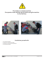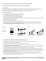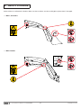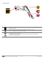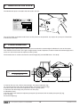
1
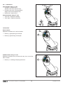
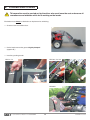
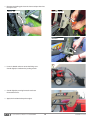
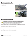
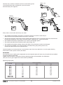
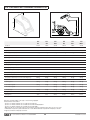
LOADER
MX C1
MX C2
MX C3u
MX C3
MX C3+
MX 30C+
User manual
Please read carefully before using
the MX loader
UK 362942 AJ - 0215
Original manual
Dear user,
We thank you for placing your trust in our product and hope you will find your MX loader satisfactory in every
way.
By taking a few minutes to read this manual, you will be able to obtain the best results from your MX loader
to the full, prolong its service life and ensure safe operation.
This loader user manual is a very important document, please keep it for future reference as required.
Make it available to any other users and hand it over it to any new owner should your MX loader be sold on.
The illustrations and technical data shown in this document might not exactly correspond to your loader,
operating conditions will nevertheless remain the same.
The loader should be subject to handover from the dealer to the user.
The demonstration of the equipment to be delivered should include:
—
—
—
—
The safety instructions.
Hitching and unhitching the loader.
Hitching and unhitching the work implement.
Full use of the controls.
In the event that one of these four necessary items is omitted, you should immediately contact
your dealership.
TABLE OF CONTENTS
1. SAFETY INSTRUCTIONS
6
2. SAFETY STICKERS
8
3. IDENTIFICATION PLATE
10
4. COUNTERWEIGHT
10
5. CONTROL
11
6. LOADER UNHITCHING 13
7. LOADER HITCHING
16
8. IMPLEMENT UNHITCHING - MX C3, C3+, 30C+ LOADERS
18
9. IMPLEMENT HITCHING - MX C3, C3+, 30C+ LOADERS
19
10. IMPLEMENT UNHITCHING / HITCHING - MX C1, C2, C3u LOADERS
21
11. LEVEL INDICATOR - MX C3, C3+, 30C+ LOADERS
21
12. 3rd FUNCTION *
22
13. MACH 2 *
22
14. SHOCK ELIMINATOR *
23
15. LOADER MAINTENANCE
23
16. SAFETY WHILE LIFTING *
25
17. USAGE RECOMMENDATIONS
25
18. TECHNICAL SPECIFICATIONS
26
* Depending on configuration
The loader is a complex machine.
The operator must read this manual before using the machine
for the first time.
Familiarise yourself with:
—
—
—
—
The safety instructions,
Hitching and unhitching the loader,
Hitching and unhitching work implements,
Full use of the controls.
• 19, rue de Rennes • BP 83221 • F - 35690 ACIGNÉ
5
Modification reserved
1. SAFETY INSTRUCTIONS
1.1 SAFETY INSTRUCTIONS AND RECOMMENDATIONS
—
—
—
—
—
—
—
—
—
—
—
—
—
—
—
—
—
Only control the loader from the control station. Keep controlling until movements stop.
Do not leave the control station without stopping all control movements (control lever locked).
Never leave the tractor with the loader lifted. After using the loader, park the tractor with the loader lowered to the ground.
All persons must be kept away from the area in which the loader is moving while it is in operation. If any lifting
operations require the presence of a person near the load, the MX loader must be fitted with a safety device
(see the "SAFETY WHILE LIFTING AND DUMPING" section).
The operator must use an implement designed and recommended by MX for the work to be carried out.
Carrying or lifting persons using the loader is forbidden.
Ensure tractor stability by using a suitable counterweight (see the "COUNTERWEIGHT" section).
Restrict all movements with the load lifted as he tractor may become unbalanced.
The maximum front axle loading specified by the tractor manufacturer must not be exceeded.
In order to limit stresses on the front axle and steering ram, and to limit tyre wear, move forwards or backwards
when steering.
The maximum loading on the front tyres specified by the tyre manufacturer must not be exceeded.
Check tyre pressures regularly.
Check periodically to ensure that safety pins and bolts are in place. Do not replace them with any other items such as:
nails, wire, etc.
For full use of the MX loader, the tractor must be fitted with a falling object protective structure, or at the least a roll-over
protective structure with four uprights. If this is not the case, limit the use of the MX loader (see the "LOADER USE
LIMITS" section). Caution: the protective fitting must be in active position while working.
Watch out for overhead electricity and telephone lines, guttering, framework, etc. when moving with the loader in
raised position.
In compliance with standard EN 12525 + A2 2010, the controls for operating the loader and implements must be
"sustained action" type except for the floating position which can be held in place by a notching system.
Any fault diagnosis and/or removal of parts must be carried out by a professional who shall start by guaranteeing
that the work will be carried out safely for him and his environment, notably in the case of work on a lifted loader.
• 19, rue de Rennes • BP 83221 • F - 35690 ACIGNÉ
6
Modification reserved
1.2 LOADER USE LIMITS ON A TRACTOR WITH A ROLL CAGE WITH 2 UPRIGHTS
Additional information for a tractor fitted with a roll cage with two uprights.
1.2.1 Warning
If the tractor is not fitted with a falling object protective structure or a roll-over protective structure with four uprights
(tractor with roll cage with 2 uprights), the driver is exposed to a permanent risk when handling loads.
Reminder: only implements recommended by the MX loader manufacturer may be used.
1.2.2 Usage precautions
For safe work, the following usage precautions must be observed:
— Use the implement designed for the work to be carried out.
— Adjust the indicator rod according to the implement used.
— Ensure the stability and hold of the load in the implement.
— The maximum loading level of the implement must not exceed the lowest side for bulk loads, and not exceed the height
of the backplate for unit loads (see Fig. 1).
— Move the tractor-loader unit carefully.
— Travel with the load at ground level and at moderate speed.
— During a lifting operation and when moving, keep your eyes on the load from when the implement’s pivot point (A)
passes the horizontal of the loader’s pivot point (B) (see Fig. 2). If necessary, correct the position of the implement
so that the load is never directed towards the driver (see Fig. 3).
Fig. 1
Fig. 2
Bulk load
Fig. 3
(B)
(A)
(B)
(A)
Unit load
Pallet type
1.3
OK
NON-COMPLIANCE WITH THE INSTRUCTIONS FOR SAFETY AND USE
—
—
—
—
The MX loader’s hydraulic circuit is designed to withstand a maximum service pressure of 200 bar.
Never make any changes to the hose connections.
Breaking lead seals will void any liability on the part of MX for all its equipment.
Any assembly of the MX loader which ignores the recommendations of the MX price list in force at the purchase date
cancels the MX guarantee for the whole supply.
— Any modification to any part of the MX supply (implements, loader, frame, etc.), or use of an implement or component
installed on the MX loader not of MX origin, cancels the MX guarantee on the entire supply.
— Use only genuine MX spare parts. Do not carry out any modifications yourself or have anyone else do so on your MX
loader and its implements (mechanical, electrical, hydraulic or pneumatic specifications) without seeking prior approval
in writing from MX. Failure to comply these rules may make your MX loader hazardous. In the event of damage or injury,
MX shall not be held responsible in any way.
— Warranty cover will cease immediately in the event of failure to observe the standards and instructions for use
and maintenance of the MX loader as stipulated in the user manual. MX shall not be held responsible for accidents
that might result from actions contrary to these restrictions.
• 19, rue de Rennes • BP 83221 • F - 35690 ACIGNÉ
7
Modification reserved
2. SAFETY STICKERS
Safety stickers are affixed to the loaders. Make sure these stickers are clean and legible; replace them if damaged.
— MX C1, C2 loaders
— MX C3 loaders
• 19, rue de Rennes • BP 83221 • F - 35690 ACIGNÉ
8
Modification reserved
— MX 30C+ loaders
Familiarise yourself with the safety instructions in the user manual before using or
working on the loader.
Follow the loader hitching and unhitching procedure given in the user manual.
Use the anchoring points when handling the loader.
Handling above people is prohibited.
It is prohibited to use the loader and its implements for any other purposes than handling
the materials it was designed for.
• 19, rue de Rennes • BP 83221 • F - 35690 ACIGNÉ
9
Modification reserved
3. IDENTIFICATION PLATE
The identification plate is located inside the loader’s left arm.
19, rue de Rennes F - 35690 ACIGNÉ
Désignation/
Designation
Type / Model / Typ
Poids à vide
Unloaded weight / Leergewicht
Année / Year
kg
328462
N˚ de série
Serial number
Seriennummer
The serial number and loader model shown on this plate must be quoted in any request for spare parts information
or technical assistance.
4. COUNTERWEIGHT
The stability of the tractor-loader unit can only be ensured with a counterweight installed on the rear of the tractor.
This should ensure that 20% of the gross weight (tractor, loader, implement, maximum load and counterweight) bears
on the rear axle of the tractor for optimum working safety.
The formula below is used to calculate the counterweight (M) (standard EN12525 + A2 2010).
M>
5 N b + I2 (P + N - 5 G)
5 (I1 + I2) - I2
G: Load on the rear axle, with no counterweight, with empty implement (kg).
G1: Load on the front axle, with no counterweight, with empty implement (kg).
b: Distance from front axle to the implement’s centre of gravity (mm).
I1: Distance from the linkage arm pin to the rear axle (mm).
I2: Wheelbase (mm).
N: Usable load of the loader for implement pivot point (A) horizontal with the loader pivot point (B) (kg).
P: G + G1 (kg).
M: Counterweight (kg).
• 19, rue de Rennes • BP 83221 • F - 35690 ACIGNÉ
10
Modification reserved
5. CONTROL
Reminder: Never leave the tractor with the loader lifted.
Every control valve with spool generates an internal leak required for
proper operation.
5.1 Control with the tractor’s control valves
Refer to the user manual for the tractor.
5.2 Control with the MX control valve
5.2.1 Handle setting *
To ensure comfortable control of the loader, the handle’s position
can be adjusted.
* only for control on MX C2 (if tractor with cab), C3 and
30C+ loaders.
5.2.2 Safety
To prevent any unwanted control of the loader, the MX monolever
can be locked.
Move the unlocking lever (1).
— (A): released position.
— (B): locked position.
• 19, rue de Rennes • BP 83221 • F - 35690 ACIGNÉ
11
Modification reserved
5.2.3 Movements
Y
X
First function: along "Y" axis
— Forwards = loader lowered
(Double action of the hydraulic ram).
— Forwards after notch = floating position
(Single action of the hydraulic ram).
— Backwards = loader raised.
Second function: along "X" axis
— To the left = implement crowding.
— To the right = implement dumping.
Y
X
3rd function:
Direct control:
Equipment available on C1 and C2 loaders.
1
— Button (1): grab opening, for example.
— Button (2): grab closing, for example.
2
Cabled control: along "X" axis
Equipment available on C2 (if tractor with cab), C3u, C3 and C3+,
30 C+ loaders.
1
— Button (1) + crowding or dumping movement.
• 19, rue de Rennes • BP 83221 • F - 35690 ACIGNÉ
12
Modification reserved
6. LOADER UNHITCHING
This operation must be carried out by the driver who must leave the seat and ensure all
manoeuvres are forbidden while he is working on the loader.
The loader must always be hitched to an implement for unhitching.
— Choose a level and solid surface.
— Put the implement on the ground slightly dumped
(approx. 20°).
— Install any parking stands.
MX C1, C2
MX C3u, C3, C3+
MX 30C+
• 19, rue de Rennes • BP 83221 • F - 35690 ACIGNÉ
13
Modification reserved
— Remove the locking pins from the frame and put them into
the open holes.
MX C1, C2
MX C3u, C3, C3+
MX 30C+
— Lower in double action to retract the lifting rams.
Crowd slightly to set down the parking stands.
— Crowd slightly by moving forwards to release
the bracket frames.
— Apply the hand brake. Stop the engine.
• 19, rue de Rennes • BP 83221 • F - 35690 ACIGNÉ
14
Modification reserved
— Fully decompress all the hydraulic circuits.
— Close the valve and disconnect the hydraulic couplings.
— Install protection caps (clean) on the male and
female couplings.
Stow the hoses on the loader.
— Reverse the tractor slowly, to clear the loader from
the bracket.
• 19, rue de Rennes • BP 83221 • F - 35690 ACIGNÉ
15
Modification reserved
7. LOADER HITCHING
— Advance the tractor slowly so that the bracket is approx. 5 cm
behind the frames.
— Apply the hand brake. Stop the engine.
— Fully decompress all the hydraulic circuits.
— Connect the hydraulic couplings and follow the colours.
— Open the valve.
• 19, rue de Rennes • BP 83221 • F - 35690 ACIGNÉ
16
Modification reserved
— Dump the implement to lift the front of the loader: by pivoting,
the frames fit into the bracket yokes.
— Lift the loader 0.3 m above the ground.
0.3 m
— Lock the loader frame onto the bracket with the spindles
and safety pins.
MX C1, C2
MX C3u, C3, C3+
MX 30C+
— Stow the parking stands.
• 19, rue de Rennes • BP 83221 • F - 35690 ACIGNÉ
17
Modification reserved
8. IMPLEMENT UNHITCHING - MX C3, C3+, 30C+ LOADERS
This operation must be carried out by the driver who must leave the seat and ensure all
manoeuvres are forbidden while he is working on the loader.
— Select a stable parking area.
— Lower the implement horizontally 0.3 m above the ground.
— Apply the hand brake. Stop the engine.
0.3 m
— Stand on the left side of the loader.
— Pull the handle fully towards you, then move it backwards to
lock it, springs compressed.
MX 30C+
MX C3, C3+
"Clac"
• 19, rue de Rennes • BP 83221 • F - 35690 ACIGNÉ
18
Modification reserved
— Start up the tractor, then lower the loader by dumping.
When the implement touches the ground, reverse slightly
in line and continue to lower the loader.
9. IMPLEMENT HITCHING - MX C3, C3+, 30C+ LOADERS
This operation must be carried out by the driver who must leave the seat and ensure all
manoeuvres are forbidden while he is working on the loader.
— Make sure that the unlocking lever is in "HITCHING" position:
spindles in, springs compressed.
MX 30C+
MX C3, C3+
— Approach the loader in line with the implement, with
the implement carrier slightly dumped.
MX 30C+
MX C3, C3+
• 19, rue de Rennes • BP 83221 • F - 35690 ACIGNÉ
19
Modification reserved
— MX C3, C3+ loaders
Fit the rounds of the hitching frame into the hooks of
the implement.
Lift the loader: locking is automatic.
Caution - crush hazard! Do not put your hands
near the implement detector - risk of locking.
— MX 30C+ loader
Fit the rounds of the hitching frame into the hooks of
the implement.
Crowd to maximum and continue to advance until the locking
lever trips.
Checks to be carried out before starting work:
Press the implement down on the ground (the tractor’s front wheels lift) to check correct locking.
Operate each moving part fully, in each direction, to check the sealing of the hydraulic circuit
and the correct routing of the hoses.
• 19, rue de Rennes • BP 83221 • F - 35690 ACIGNÉ
20
Modification reserved
10. IMPLEMENT UNHITCHING / HITCHING - MX C1, C2, C3u LOADERS
10.1 Implement unhitching
— Select a stable parking area.
— Lower the implement to the ground.
— Remove the safety pins, then the dumping-implement ram
link pins (1).
— Remove the safety pins, then the boom-implement link pins (2).
1
2
10.2 Implement hitching
— Mount the boom-implement link pins, then the safety pins (1).
— Mount the dumping ram link pins, then the safety pins (2).
Adjust the ram rod extensions as required.
2
1
11. LEVEL INDICATOR - MX C3, C3+, 30C+ LOADERS
The level indicator enables implement positioning when the loader is lowering. It is on the right side of the loader.
It can be adjusted according to the implement used.
Indicator
Bucket parallel to ground
• 19, rue de Rennes • BP 83221 • F - 35690 ACIGNÉ
21
Modification reserved
12. 3rd FUNCTION *
Positioned on the loader cross-bar, the two front couplings
enable the hydraulic supply of a grab or other implement
requiring double acting operation.
MX C1, C2
For easier connection-disconnection, stop the engine
and decompress the 3rd function hydraulic circuit.
MX C3u, C3, C3+
MX 30C+
13. MACH 2 *
The MACH 2 (optional) enables effortless once-only connection
of the implement’s hydraulic functions.
MX C3u, C3, C3+
The MACH 2 kit includes the hoses for supplying
MX implements.
MX 30C+
* Depending on configuration
• 19, rue de Rennes • BP 83221 • F - 35690 ACIGNÉ
22
Modification reserved
14. SHOCK ELIMINATOR *
Shocks are eliminated during movement or when stopping
the loader quickly when lowering.
MX C3u, C3, C3+
— Supension on (1).
— Supension off (2).
2
1
MX 30C+
1
2
* Depending on configuration
15. LOADER MAINTENANCE
Drain the tractor’s hydraulic circuit regularly and change the filters following
the manufacturer’s recommendation.
Polluted oil stops lubricating, and wears all the hydraulic components
(pumps, control valves, rams). Even clear oil can be overused.
For tractor maintenance operations, it is strongly recommended to unhitch the loader. Unhitching is a simple quick
operation that provides the best guarantees of safety and efficiency for tractor maintenance.
For any work with the lifted loader, the loader must be locked in position:
Closure of the supply valve of the lifting rams (see the "LOADER UNHITCHING" section).
When using a pressure washer, avoid spraying water on electric components.
Clean the implement and the front of the loader after every use.
Slurry acid, fertiliser and silage can damage paint, steel and pivot points.
• 19, rue de Rennes • BP 83221 • F - 35690 ACIGNÉ
23
Modification reserved
Lubricate every 10 hours and after each wash (water drives grease
out) and particularly after washing with a pressure washer.
See lubrication points opposite.
MX C1, C2
MX C3+
MX 30C+
Every month, or more often with heavy use, check:
— The condition of the loader’s pivot points. As required, replace wear bushes and/or the pins.
Wear bushes must be replaced if they are less than 1 mm thick.
— The level of the tractor’s hydraulic oil and the sealing of the hydraulic circuit. If you find any internal or external leaks
on hydraulic components (rams, pipes, connectors, Mach, couplings, etc.), contact your dealer.
— The condition of the hoses: replace them if any cracks or oil seepages appear.
— The correct operation of the monolever (cables, play, locking, etc.).
— The condition of the electric cabling. Contact your dealer if any connectors or cables are damaged.
— The mechanical condition (any cracks, distortion, end stop matting, play, parking stands, etc.).
Contact your dealer if there is any abnormal wear.
Check the tightness of the bracket after 10 and 50 hours work, then every 100 hours or at each engine draining
of the tractor. If loose, please contact your dealer.
IMPORTANT:
Any fasteners/screws needing to be retightened must be inspected, replaced if necessary, cleaned and reassembled
using thread locking compound.
Tighten fasteners/screws in accordance with the tightening torque recommended in the table below.
(The use of an air gun to tighten the tractor’s bolts is prohibited)
Tightening torque (Nm)
Thread
M8
M 10
M 12
M 14
M 16
M 18
M 20
M 22
M 30 x 150
M 40 x 150
Class of fastening
10.9
29
58
101
160
245
340
475
640
8.8
21
42
72
114
174
240
340
455
500
500
• 19, rue de Rennes • BP 83221 • F - 35690 ACIGNÉ
24
12.9
35
70
121
193
295
405
570
765
Modification reserved
16. SAFETY WHILE LIFTING *
If the loader is used for any lifting operations requiring the presence of persons near the load when the loader is in raised
position, the hydraulic circuit of the lifting arms must be fitted with a safety device. This in compliance with standard
EN 12525 + A2 2010.
* Depending on configuration
17. USAGE RECOMMENDATIONS
— Each implement has been designed for a specific use and has its own resistance limits.
— Land clearing and stump pulling are prohibited. This work must be done with specialized machinery and is not
appropriate for the agricultural loader.
— Use the tractor’s driving power to penetrate into the material to be moved rather than speed, which subjects the loader
and tractor to high stresses.
— When the load to be moved is too big, do not force on the hydraulic components. The same applies when the rams
are fully extended. Release the control valve levers
Work flexibly and carefully.
• 19, rue de Rennes • BP 83221 • F - 35690 ACIGNÉ
25
Modification reserved
18. TECHNICAL CHARACTERISTICS
(B)
4
(C)
2 1
(A)
5
3
MX
C1
MX
C2
MX
C3u
MX
C3
MX
C3+
MX
30C+
Length (A)
1.20 m
1.20 m
1.32 m
1.45 m
1.45 m
1.75 m
Width (B)
0.90 m
0.90 m
1.02 m
1.05 m
1.05 m
1.05 m
Height (C)
1.05 m
1.05 m
1.45 m
1.45 m
1.55 m
1.25 m
Min. weight (with no option)
85 kg
90 kg
200 kg
220 kg
240 kg
205 kg
Max. height at implement pivot *
1.92 m
1.92 m
2.60 m
2.60 m
2.60 m
2.60 m
Max. height under horizontal bucket (1) #
1.80 m
1.80 m
2.40 m
2.40 m
2.40 m
2.35 m
Max. height under dumped bucket (2) #
1.50 m
1.50 m
2.05 m
2.05 m
2.05 m
2.00 m
Digging depth (3) #
0.10 m
0.10 m
0.15 m
0.15 m
0.15 m
0.15 m
Dumping angle at full height (4) #
40°
40°
35°
50°
50°
68°
Dumping angle at ground level #
125°
125°
127°
140°
140°
122°
Crowd angle at ground level (5) #
30°
30°
25°
45°
46°
45°
Front unloading range
900 mm
900 mm
960 - 1060 mm
960 - 1060 mm
960 - 1060 mm
1050 - 1150 mm
Lifting force at implement pivot *
450 kg
450 kg
750 kg
750 kg
750 kg
1400 kg
Lift capacity at implement pivot over the entire lifting range *
420 kg
420 kg
740 kg
740 kg
740 kg
990 kg
On the ground
390 kg
390 kg
510 kg
420 kg
530 kg
1250 kg
At 1 m above ground
370 kg
370 kg
520 kg
440 kg
530 kg
1100 kg
At 2 m above ground
–
–
500 kg
430 kg
530 kg
930 kg
350 kg
350 kg
470 kg
380 kg
530 kg
710 kg
Lifting time
3 sec
3 sec
4.5 sec
4.5 sec
4.5 sec
3.8 sec
Dumping time
3 sec
3 sec
2.1 sec
2.2 sec
2.2 sec
3.3 sec
Payload **
At max. height
Data may vary depending on the type of tractor being equipped.
Characteristics measured at:
- pressure of 140 bar and flow rate of 15 litres/min for MX C1.
- pressure of 140 bar and flow rate of 20 litres/min for MX C2/C3u/C3/C3+.
- pressure of 180 bar and flow rate of 30 litres/min for MX 30C+.
* Only payloads are counted. The figures at ground level and at the implement pivot axis are not to be used.
** MX C3/C3+: Payload on pallet at 0.50 m out on forks MX C1/C2/C3u: Payload with multipurpose bucket.
# Figures provided for multipurpose bucket.
• 19, rue de Rennes • BP 83221 • F - 35690 ACIGNÉ
26
Modification reserved
• 19, rue de Rennes • BP 83221 • F - 35690 ACIGNÉ
27
Modification reserved
DECLARATION OF CONFORMITY
The manufacturer:
MX
19, Rue de Rennes. F - 35690 Acigné.
Hereby declares that the material:
Front loader MX FR or T406 or T408 or T410 or T412 or T414 or T417 or T418
or T406s or T408s or T410s or T412s or T414s or T417s
or
Front loader U303 or U304 or U305 or U306 or U307 or U308 or U309 or U310 or U312
or U303s or U304s or U305s or U306s or U307s or U308s or U309s or U310s or U312s
or
Front loader C1 or C2 or C3 or 20C+ or 25Cu or 25C+ or 30C+
or
Loader implement BMS or BRDS or GV or BQU or BF + GF or CGU or LAL or TR or BMSC or BFC +
GFC or TRC or BT or BR or BL or BC or BF or BRU or BFU or LE or CL or BRC or BFC or LC
or
Implement for telescopic handler loader BMSA or BFA or CGA or BTA or TR or BCA
or
Feeding bucket BD1202 or BD 1402 or BD 2002 or BD 2402 or BD 3102
or
Manubal L or C40 or V40 or V50 or V60 or V500 or W500 or V7000
or
Front linkage R05 or R08 or R10 or R12 or R16 or R20 or R28 or R38 or R53
or
Weight M250 or M400 or MM600 or MM900 or MM1200 or MM1500 or MM400AD or MBX
serial number:
,
please write in the box above the serial number given on the
equipment’s nameplate.
included in the list of serial numbers 49999_ 11 00101 to 499999_ 24 36522,
is in conformity with the Machinery Directive 2006/42/EC
(and satisfies standard NF EN 12525+A2 of May 2010).
Mr Mailleux Loic, 19 rue de Rennes at Acigné (35690), is authorised to prepare the technical file.
Acigné, 13 October 2014
Loïc Mailleux
Technical Director
19, rue de Rennes
BP 83221
F - 35690 ACIGNE
Tel.: +33 (0)2 99 62 52 60
Fax: +33 (0)2 99 62 50 22
E-mail: [email protected]