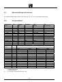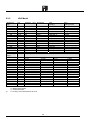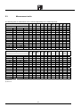
1
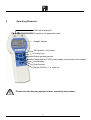
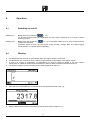
MicroCal P4
Portable Calibrator
User Manual MM850600 ed. 01
User Manual MM850600 ed.01
INTRODUCTORY NOTE
This manual contain with all the information you need to operate and maintain the portable calibrator MicroCal P4
and his accessories.
Eurotron has used the best care and efforts in preparing this book and believes the information in this publication are
accurate. The Eurotron products are subjected to continuous improvement, in order to pursue the technological
leadership; these improvements could require changes to the information of this book.
Eurotron reserves the right to change such information without notice.
No part of this document may be stored in a retrieval system, or transmitted in any form, electronic or mechanical,
without prior written permission of Eurotron Instruments S.p.A.
Any maintenance operation must be carried out by qualified personnel only. Eurotron supplies instructions and
operative procedures for any operation on the instrument. We recommend to contact our technicians for any support
requirements.
MicroCal P4 are fully tested in conformity with the directive n°89/336/CEE Electromagnetic Compatibility. Eurotron
shall not be liable in any event, technical and publishing error or omissions, for any incidental and consequential
damages, in connection with, or arising out of the use of this book.
Copyright ©, 2006
Eurotron Instruments S.p.A.
Viale Fratelli Casiraghi 409/413
20099 Sesto San Giovanni (MI) – Italy
Tel.: 02 248820.1 – Fax: 02 2440286
e-mail: [email protected]
2
User Manual MM850600 ed.01
SUMMARY
1
MICROCAL P4 ORDERING CODE........................................................................................ 4
2
OPERATING ELEMENTS ...................................................................................................... 5
3
DESCRIPTION ........................................................................................................................ 6
3.1
3.2
3.3
4
Operating modes........................................................................................................................................6
Safety information.......................................................................................................................................6
Notes for instruments with Ex-protection ....................................................................................................7
OPERATION ........................................................................................................................... 8
4.1
4.2
4.3
4.4
4.4
4.6
4.6.1
4.7
4.7.1
4.7.2
4.7.3
4.8
4.8.1
4.8.2
4.8.2.1
4.8.2.2
4.8.2.3
4.8.2.4
4.8.2.5
4.9
4.10
4.11
4.11.1
4.11.2
5
Switching on and off ...................................................................................................................................8
Working ......................................................................................................................................................8
Lighting.......................................................................................................................................................9
Pneumatic connection ................................................................................................................................9
Functions and operating modes ...............................................................................................................10
Menu selection and set-up........................................................................................................................10
Navigation within the Menu selection..................................................................................................10
Data logging .............................................................................................................................................12
Data recording....................................................................................................................................12
Transfer of data to a PC .....................................................................................................................13
Deleting data ......................................................................................................................................13
Communication ........................................................................................................................................14
IR/RS232-Protocol .............................................................................................................................14
IR-Hardware of the instrument............................................................................................................16
Initialisation ........................................................................................................................................16
Setting the baudrate ...........................................................................................................................16
Control commands .............................................................................................................................17
Data Type Key....................................................................................................................................21
Notes regarding control commands ....................................................................................................21
Battery replacement .................................................................................................................................22
Notes for instruments with Ex-certification ..........................................................................................22
Calibration ..........................................................................................................................................22
Manual re-calibration ..........................................................................................................................22
Full-scale value ..................................................................................................................................23
SPECIFICATIONS ................................................................................................................ 24
5.1
5.2
5.2.1
5.2.2
5.3
5.3.1
5.4
5.5
Technical data ..........................................................................................................................................24
Measuring Range and Precision...............................................................................................................25
European Model .................................................................................................................................25
USA Model .........................................................................................................................................26
Measurement units ...................................................................................................................................27
Conversion factors .............................................................................................................................28
Mains supply unit connection....................................................................................................................28
Maintenance and storage .........................................................................................................................28
6
WARNING MESSAGES AND FAULTS ............................................................................... 29
7
ACCESSORIES .................................................................................................................... 30
8
SUMMARY OF TECHNICAL CHARACTERISTICS............................................................. 31
APPENDIX ............................................................................................................................................ 33
9
CERTIFICATES .................................................................................................................... 34
9.1
9.2
Warranty terms.........................................................................................................................................34
Letter of conformity...................................................................................................................................34
3
User Manual MM850600 ed.01
1
MicroCal P4 Ordering Code
3209 STD - A - B - C
Each MicroCal P4 STD pack comes with: one pressure calibrator, charger, instruction manual, Eurotron calibration
certificate
3209 IS - A - B - C
Each MicroCal P4 IS is Eex ia IIC T4 compliant and the pack comes with: one pressure calibrator, charger,
instruction manual, Eurotron calibration certificate
Table A
0
1
2
Sensor Accuracy
±0.2% ±1 digit
±0.1% ±1 digit
±0.05% ±1 digit
Table B
D - 25m
D - 70m
D - 200m
D - 300m
D - 500m
D - 1000m
A - 1100m
D - 2000m
G - 2000m
A - 2000m
D - 7500m
G - 7500m
A - 7500m
D - 17
G - 17
G - 35
G - 70
G - 90
Sensor Range - Available accuracy
25 mbar gauge and differential dry sensor - 0.1% / 0.2%
70 mbar gauge and differential dry sensor - 0.05% / 0.1% / 0.2%
200 mbar gauge and differential dry sensor - 0.1% / 0.2%
300 mbar gauge and differential dry sensor - 0.05% / 0.1% / 0.2%
500 mbar gauge and differential dry sensor - 0.1% / 0.2%
1000 mbar gauge and differential dry sensor - 0.05% / 0.1% / 0.2%
1100 mbar absolute sensor - 0.1% / 0.2%
2000 mbar gauge and differential dry sensor - 0.05% / 0.1% / 0.2%
2000 mbar gauge wet sensor - 0.1% / 0.2%
2000 mbar absolute dry sensor - 0.05% / 0.1% / 0.2%
7500 mbar gauge and differential dry sensor - 0.05% / 0.1% / 0.2%
7500 mbar gauge wet sensor - 0.1% / 0.2%
7500 mbar absolute dry sensor - 0.05% / 0.1% / 0.2%
17 bar gauge and differential dry sensor - 0.05% / 0.1% / 0.2%
17 bar gauge wet sensor - 0.1% / 0.2%
35 bar gauge wet sensor - 0.1% / 0.2%
70 bar gauge wet sensor - 0.1% / 0.2%
90 bar gauge wet sensor - 0.1% / 0.2%
4
User Manual MM850600 ed.01
2
Operating Elements
Infra-red interface IR
Connection for pneumatic tube
Graphic display
Zero position / Exit menu
Function key
Select operating mode
Connection for 6 VDC power supply (not present in Ex-models)
Hold display
Start function
Switch On/Off (> 1 s: Light on)
Please note this warning symbol in these operating instructions!
5
User Manual MM850600 ed.01
3
Description
The MICROCAL P4 digital pressure gauge is a pressure-measuring instrument with an integrated pressure sensor for
the measurement of differential, relative or absolute pressures and vacuum. Its versatile range of functions and high
precision render it suitable for a wide range of applications. Via the infrared interface (IR) and SCPI (Standard
Commands for Programmable Instruments) commands, the MICROCAL P4 can communicate with a PC. Its
operation is very simple, and supports the user in his measurement tasks.
3.1
•
•
•
•
•
Operating modes
Pressure measurement / Differential pressure
Min./Max. values
Mean value (average)
Pressure change rate
Data logging
Selectable configuration possibilities:
•
•
•
•
•
Data logging
Æ Interval time, print/transfer, deleted memory
Configuration
Æ Measurement units, display filter, auto. switch-off time, auto zero, lighting level, etc.
Average period (period for determining average value)
Date and Time (real-time clock)
Calibration
Æ Date of last calibration date, manual recalibration
Correct usage
The explosion-proof version is designed as a test and measuring instrument for temporary use within the process,
and is certified for EEx ia IIC T4 (Zone1).
Its correct usage does not include permanent or long-term measurement without supervision.
3.2
Safety information
The pressure values and overload levels stated on the rating plate and quoted in these operating instructions must
not be exceeded, as otherwise the pressure sensor could be destroyed or there could be a risk of injury.
Only use pressure hoses with a maximum loading capacity corresponding to that necessary for the application.
Ensure that the pneumatic hoses are securely fitted! Do not use damaged or kinked hoses.
Do not open up the instrument (this would void the guarantee and the Ex-certification).
The instrument must be stored within the permissible storage temperature range.
The instrument without Ex-protection must not be put into operation in an
explosive environment!
6
User Manual MM850600 ed.01
Wear eye protection if working with pressures > 1bar!
3.3
Notes for instruments with Ex-protection
The battery compartment must not be opened inside the Ex-area!
In areas where there is a risk of explosion, the instrument may only be used with the
approved types of batteries. The battery types to be used, depending on the
temperature class, can be found on Page 33 of the Appendix to the Operating
Instructions.
Only use approved batterys type LR6 according to IEC 60086-1 provided by the
manufacturer, as described in the appendix.
7
User Manual MM850600 ed.01
4
Operation
4.1
Switching on and off
Switching on
Briefly press the On/Off key (
) (< 1 s)
For precise measurements, the MICROCAL P4 must first be switched on for at least 1 minute
(warm-up phase).
Switching off
Briefly press the On/Off key (
) (< 1 s), or automatic switch-off 3,10 or 60 minutes after the
last time key operation
(automatic switch-off does not take place during Average, Change Rate and Data Logging
measurements or in IR and network operation).
4.2
Working
•
•
•
The MICROCAL P4 switches on automatically when the supply voltage is connected.
The MICROCAL P4 continues to work in battery mode following an interruption of the supply voltage
•
In case of a change in temperature, the MICROCAL P4 must be allowed to adapt to the new ambient
temperature for a least 30 minutes while switched off in order to attain the best measurement accuracy.
The day/time, battery level and accuracy will be briefly displayed at switch on:
•
After switch-on, the MICROCAL P4 switches to the last operational mode used, e.g.:
•
With the display filter activated, wait until the transient effect finishes (approx. 5 s).
8
User Manual MM850600 ed.01
4.3
Lighting
Switching on
Press the On/Off-key (
Brightness control
In the Menu, select the Configuration → Lighting function and select an adjustment of Off,
Level 1, Level 2 or Level 3.
The Ex-version MICROCAL P4 only has the levels Off and Level 1.
Switching off
) (< 1 s)
Briefly press the On/Off key (
(switch off the instrument), or automatic switch-off after 20 s.
With mains operation, the MICROCAL P4 must be switched off manually.
4.4
) for > 1 s
Pneumatic connection
Designation
Hose 4/6 mm
NPT1/8“ internal
Plug in nipple „Rectus“ Type 20
M10 x 1 internal thread (for „Minimess“ connector)
Pressure range
≤ 7,5 bar
10 ... 90 bar
≤ 30 bar
all
ENSURE THAT THE PNEUMATIC HOSES ARE CONNECTED CORRECTLY!
+P HIGHER PRESSURE
S+ LOWER PRESSURE (NOT AVAILABLE WITH THE ABSOLUTE AND RELATIVE PRESSURE VERSION)
When screwing onto a coupling, it is important to hold the coupling steady with a
wrench to prevent any turning!
Never secure by holding the casing itself!
9
User Manual MM850600 ed.01
4.4
Functions and operating modes
Key
Functions
PRESSURE
Difference
V
MIN/MAX
W
AVERAGE 4)
CHANGE RATE 5)
Data logging
1.
2.
3.
4.
5.
1)
clear
hold
Zero:
sets
measured value to
zero 3)
Sets Max/Min to
current
measured
value
Freezes
all
To Menu selection
current
measurement
values
Sets
measured
value to zero 3)
Start 2)
--
Starts measuring
Stop/Menu
--
Starts
logging
data
Once a measurement procedure has been started, the menu selection is blocked.
During a measurement procedure (after Start has been pressed), you can switch between functions. This
permits, for example, the observation of the Min/Max function during data logging.
The Clear key has no function in the absolute pressure instruments.
The AVERAGE function creates an arithmetic average value of all measured values during the time period
selected in the menu. After expiry of the time period, the average value will be displayed.
Measurement of the leak rate (diff/gauge sensor) or tendency (abs. sensor). The pressure change (Change
Rate) from the start time to the current time will be displayed. The first display occurs 10 s after the start.
4.6
Menu selection and set-up
4.6.1
Navigation within the Menu selection
clear
Brief (< 1 s)
Long (> 1 s)
1 level back
Back to the function level/operating modes
Selection of Set-up/Functions
VW
) is pressed.
The functions shown inverted on the display will be carried out if the Function key (
The currently selected setting for values is marked with '9'. In the following table, the default values are
correspondingly marked (factory settings).
Key
Notes
Data logging
Interval
Interval period
9
10
User Manual MM850600 ed.01
Key
Notes
Set with V/W/ EDIT/OK
V
W
Print Data Logging
Press 'Start'
Print/send via IR
Press 'Clear'
Deletes the data memory
Clear Memory
Configuration
Pressure Unit
9
Display Filter
Filters the display values 1)
9
Auto-Off
Auto. switch-off
9
Auto-Zero
Sensor auto-zeros at switch-on
if measured value < 1% FS
9
Beep
Warning beeper
9
Lighting
Only Level 1 possible for Ex-models
V
W
9
IR Interface
9
Average period
11
At
switch-on,
the
automatic
connection to the PC is activated for
2 minutes
Automatic connection is de-activated
Time period for average value
User Manual MM850600 ed.01
Key
Notes
9
Set with V/W/EDIT/OK
Date & Time
dd.mm.yyyy
hh:mm:ss
Set with V/W/ EDIT/OK
Set with V/W/ EDIT/OK
History
Manual re-calibration
Displays the last calibration date
Manual re-calibration of the zero
point and limit value
Calibration
NOTE: WITH THE FILTER FUNCTION ACTIVE, SHORT-TERM MEASUREMENT VARIATIONS SHOULD BE SUPPRESSED, RESULTING IN A
STEADIER DISPLAY. MEASURED VALUES VIA THE INTERFACE AND IN THE DATA LOGGING MEMORY WILL NOT BE FILTERED.
4.7
Data logging
4.7.1
Data recording
Every time that the Data Logging is started, an information header ("Header") will first be saved: The measured
values will then be saved sequentially. "Stop" will be saved after every interruption of the logging or if manual storage
is carried out. At the end of all the data loggings, "End" will be saved. Measured values can be uniquely identified by
their header.
Designation
Date
Time
Interval
Function
Unit
Example 1
01.01.2001
12:00:00
30 s
PRESS
mbar
1000.0
1001.1
1001.5
1000.3
999.7
Stop
Data Logging
INTEGER
Header
DISCRETE
Measurement series 1)
FLOAT
DISCRETE
End
Designation
Date
Time
Interval
Type of Data 2)
DISCRETE
Example 2
01.01.2001
12:00:00
Manual
Manual saving
Header 1st measurement
Type of Data 2)
INTEGER
DISCRETE
12
User Manual MM850600 ed.01
Designation
Function
Unit
Date
Time
Interval
Function
Unit
Date
Time
Interval
Function
Unit
1.
2.
3.
Example 2
PRESS
inHg
29.92
Stop
01.01.2001
12:00:33
Manual
PRESS
inHg
29.29
Stop
Manual saving
Type of Data 2)
1st measured value 1)
FLOAT
DISCRETE
INTEGER
Header 2nd measurement
DISCRETE
2nd measured value 1)
01.01.2001
12:01:45
Manual
PRESS
inHg
28.00
Stop
End
FLOAT
DISCRETE
INTEGER
Header 3rd measurement
DISCRETE
3rd measured value 1)
FLOAT
DISCRETE
DISCRETE
„Over“ (data type DISCRETE) for invalid pressure value
For the Data Type key.
User-interval period will, for example, be displayed as follows, “user 01:15:00”
4.7.2
Transfer of data to a PC
(with MICROCAL P4 Communication Software)
1.
2.
3.
4.
Install the IR (IrDA) -adapter according the instructions of the manufacturer.
Install the MICROCAL P4 Communication Software.
Start the MICROCAL P4 Communication Software.
Place the instrument max. 20 cm from the IR (IrDA)-Adapter and switch it on. Ensure a line-of sight connection
between instrument and IR-adapter!
If there is no communication with the instrument for more than 2 minutes, the IR interface of the instrument
turns off automatically! By restarting the instrument the IR interface is reactivated.
4.7.3
1.
2.
Deleting data
In the Menu, select the Data Logging → Clear Memory function.
Press the Clear key.
13
User Manual MM850600 ed.01
4.8
Communication
4.8.1
IR/RS232-Protocol
COM-Port Settings
Baudrate
Data bits
Parity
Protocol
Stop bit
9600
8
no
no
1
Communication Protocol
Coding
The characters are transfered as ASCII-Code.
Sending a command from PC to the instrument
<SCPI Command> [SP <Parameter 1>] [ , <Parameter 2> ] [ , <Parameter 3> ] [ , ... ]
HT [ * <CS> ] CR
Examples:
Setting the time to 07:08:09:
S Y S T : T i m e SP 0 7 , 0 8 , 0 9 HT * 2 5 5 CR
S Y S T : T i m e SP 0 7 , 0 8 , 0 9 HT CR
Reading the time:
S Y S T : T i m e ? HT * 1 4 2 CR
S Y S T : T i m e ? HT CR
(with checksum)
(without checksum)
(with checksum)
(without checksum)
Response from instrument to PC
<Return Value 1> [ , <Return Value 2> ] [ , <Return Value 3> ] [ , ...] HT * <CS> CR
SCPI Command:
CS:
Return Value:
[ ]
ASCII-character
SP
HT
CR
*
,
SCPI command according the table on following pages
Checksum
Response from instrument
Option
Hex-Code
0x20
0x09
0x0D
0x2A
0x2C
Meaning
Space
Horizontal Tabulation
Carriage Return
Asterisk
comma
SCPI Commands
There is no difference between small and capital letters.
Checksum (CS)
The use of the checksum is optional. A * indicates a following checksum. The ASCII-character * is included in the
calculation of the checksum. The checksum is calculated from the low byte.
14
User Manual MM850600 ed.01
Example:
Reading the date
S
Y
S
T
:
D
a
t
e
?
HT
*
53
59
53
54
3A
44
61
74
65
3F
09
2A
hex
83
89
83
84
58
68
97
116
101
63
09
42
dez
37D
hex
7D
hex
893
dez
125
dez
sum:
low byte:
The checksum is 125 decimal.
Command:
S Y S T : D a t e ? HT * 1 2 5 CR
S Y S T : D a t e ? HT CR
Return Value
Command processed:
Return Value = o k
Example for response:
Error
Return Value
er-001
er-110
er-113
er-109
er-101
er-108
er-203
er-999
er-002
Example:
(with checksum)
(without checksum)
o k HT * 1 3 CR
Meaning
RS232 Protocol checksum Error
Header Error; Too short
Header Error; Too many subnodes
Header Error; Query not at leaf node
Header Error; Multiple querys
Header Error; Characters after query
Header Error; Too long
Undefined Header; Undefined command
Missing parameter
Missing parameter; Boolean expected
Missing parameter; String expected
Missing parameter; Discrete expected
Missing parameter; Not of expected type
Invalid character; Terminator expected
Invalid parameter; Out of bounds
Invalid parameter; Too long
Command Protected
EEProm Read/Write Error
Fatal Command Execution Error
Checksum Error
Response: e r – 0 0 1 HT * 200 CR
After command with response value
Example:
reading time (07:08:09)
Response: 0 7 , 0 8 , 0 9 HT * 1 9 5 CR
ATTENTION
AFTER EVERY COMMAND WAIT FOR THE RESPONSE OF THE INSTRUMENT (MAX. 680 MS).
15
User Manual MM850600 ed.01
4.8.2
IR-Hardware of the instrument
The hardware of the IR-connection of the instrument is compatible with IrDA-Standard 1.0.
IR (IrDA)- Adapter
A passive IrDA-adapter has to be used which is compatibel to IrDA-Standard 1.0. The IrDA adapter ACT-220L+
from ACTiSYS Corp. (www.actisys.com) is available as accessories.
The following explanations apply to this type.
4.8.2.1
Initialisation
Remarks
ACT-220L/220L+ are programmed by toggling the control
lines RTS and DTR. These lines may not be low at the
same time during operation. In this condition the ACT220L/220L+ goes in power down mode. If DTR and RTS
are low at the same time or in an undefined condition, both
lines must be set high for at least 50 ms to leave the power
down mode.
1
DTR
0
1
RTS
0
min. 50msec
4.8.2.2
Setting the baudrate
1
DTR
0
1
RTS
0
Remarks
Before
setting
the
baudrate
the
ACT-220L/220L+ has to be initialised according
Initialisation. The baudrate is set to 9600 bps according the
opposite diagram.
A PC usually needs more than 0.5 us for an I/O-Instruction.
min. 0.5usec
16
User Manual MM850600 ed.01
4.8.2.3
Control commands
The control commands are largely defined by the Standard Commands for Programmable Instruments (SCPI).
Command
Sub-node 1
MEASure
UNITs
SYSTem
Transfer Parameters
Parameter
Data Type
:PRESsure
<interval>
INTEGER
:PRESsure?
---
---
:TEMPerature?
---
---
:PRESsure
<unit>
DISCRETE
:PRESsure?
---
---
:DATE
<yyyy>,<mm>,<dd>
INTEGER
:DATE?
---
---
:TIME
<hh>,<mm>,<ss>
INTEGER
:TIME?
---
---
---
---
---
---
<state>
BOOLEAN
---
---
:ERRor
Sub-node 2
[:NEXT]?
:VERSion?
:BEEPer
:STATe
:BATTery?
17
User Manual MM850600 ed.01
Command
Sub-node 1
:RANGe?
---
Parameter
Data Type
---
:TOLerance?
---
---
:IDENt?
---
---
:FILTer
<state>
BOOLEAN
:ZERO
---
---
:SET
Sub-node 2
Transfer Parameters
Parameter
limits
Feedback data
Feedback
type
data Description
0, 10, 25
<value>
FLOAT
Continuous transfer
measured values
---
<value>
FLOAT
Query
measured Individual value
pressure value
---
<value>
FLOAT
Query
temperature
mbar, bar,.... atm
---
---
Pressure unit input
---
<unit>
DISCRETE
Query
yyyy: 2001 ...2099
mm: 1...12
dd: 1... xx
---
---
Input date
yyyy:
mm: month
dd: day
---
<yyyy>,<mm>,<dd>
INTEGER
Query date
yyyy: year, mm: month
dd: day
0...23, 0...59, 0...59 ---
---
Input time
hh: hours, mm: minutes
ss: seconds
---
<hh>,<mm>,<ss>
INTEGER
Query time
hh: hours, mm: minutes
ss: seconds
---
INTEGER,
<Error_number>,
"<Error_description> STRING
(;<Devicedependent info>)"
Query SCPI Error Queue
STRING with ‚fixed text‘
and optional ‚free text’,
separated by a semicolon,
maximum 255 digits
18
pressure
Remarks
of Continuous measurement
with 10 or 25 M/s.
Stops with Interval=0
sensor °C,
individual
value
unit E.g., mbar, bar,.... atm
year,
User Manual MM850600 ed.01
Parameter
limits
---
Feedback data
<version>
Feedback
type
FLOAT
data Description
Remarks
ON, OFF
---
---
Beeper enable / disable
---
<value>
INTEGER
Query battery state
---
<range>
STRING
---
<tolerance>
STring
Query
sensor e.g. "1,000 mbar“
measurement
range
(in mbar)
Query sensor tolerance
e.g. '0.05 %FS'
---
<type, MOD, S/N>
STRING
ON, OFF
---
---
---
---
---
SCPI query and firm- e.g. '2001.0' , ‘FW:300’
ware version
Range 0...100, value in %
Query
identification
instrument e.g.
"MICROCAL
P400DLH200,
MOD00A,1234567“
Set filter for display
Zero measure pressure
value (ZERO)
Command
Sub-node 1
Sub-node 2
Transfer parameter
Parameter
SYSTem
:SET
:AOFF
<time>
DISCRETE
:OFF
---
---
:AZERo
<state>
BOOLEAN
:INTerval
<interval>
DISCRETE
:AVERage
<interval>
DISCRETE
:IRDA
<status>
BOOLEAN
:CONFig
DIAGnostic
:ERRors?
---
---
DISPlay
:BRIGhtness
<level>
DISCRETE
19
data
type
User Manual MM850600 ed.01
MEMory
:COPY
:DLOG?
---
---
:DELete
:ALL
---
---
*CLS
---
---
*IDN?
---
---
*STB?
---
---
*TST?
---
---
*RST
---
---
Parameter
Feedback data
limits
3min, 10min, 60min ---
Feedback
type
---
data Description
Remarks
---
---
---
Switch
ON, OFF
---
---
Enable/disable auto zero
25M./s,
1s ... 24h
10M./s, ---
---
Set interval time for Data Similar to Menu
Logging
Set auto Off time
off
instrument
10s, 30s ... 24h
---
---
Set time
Average
OFF
---
---
Set auto IrDA connection
---
<err>,<err>,<err>...
INTEGER
Query
the
memory
BIT-Error Variable
amount
of
Feedback data, err: 0...255
<message>
DISCRETE
Query
the
memory
BIT-error If Error memory deleted:
'No Errors!’
off, level 1, level 2, --level 3
---
Brightness setting
LCD backlight
---
diverse
Select Memory
Logging (cyclic)
<data>
20
period
for Similar to Menu
for EX-instrument only off and
Level 1, similar to Menu
Data Complete
reading,
Format: see 3.6.1
User Manual MM850600 ed.01
---
---
---
Delete Memory
Logging
---
---
---
Delete Status and Error
Memory
---
<type, MOD, S/N>
STRING
Query
identification
---
<data>
INTEGER
Query Status Byte
---
<data>
INTEGER
Initiate a Self-Test
---
---
---
Reset command
4.8.2.4
instrument See SYST:IDENT?
Data Type Key
Designation
INTEGER
FLOAT
I-FLOAT
Description
Decimal number, whole numbers only
Floating-point number
Floating-point number, transferred as an INTEGER.
This means that it will not be transferred in the floating-point
format, but as an INTEGER – value coded according to the IEEE754 standard.
Discrete values, do not use “ in the text, similar to Menu selection
Boolean values: ON or OFF (similar to DISCRETE)
Character string
DISCRETE
BOOLEAN
STRING
4.8.2.5
Data
Example
123
123.45
3242721280
(corresponds to -12.5)
mbar
ON
"ABCDE“
Notes regarding control commands
•
Cyclical commands
•
" (Inverted commas)
•
' (apostrophe)
•
( ) (brackets)
•
, (comma)
Commands that last longer are processed cyclically.
They will be automatically interrupted if a command occurs that requires an output.
A STRING is identified by inverted commas and a full-stop.
These must be transferred with it (unlike DISCRETE).
An apostrophe is used, for example for emphasis.
The apostrophe itself will not be transferred.
Parameter inside round brackets are optional
The brackets themselves will not be transferred.
The comma is used to separate arguments. The next argument must follow immediately
after the comma (no SPACE, ASCII-Code 32dez).
21
User Manual MM850600 ed.01
4.9
Battery replacement
The battery compartment must not be opened inside the Ex-area!
4.10
Notes for instruments with Ex-certification
Only use battery type LR6 according to IEC 60086-1 approved by the producer, as
described in the appendix.
Open the battery compartment and insert 3 x 1,5 V Mignon cell AA, IEC LR6.
Always replace all three batteries at the same time!
Ensure correct polarity!
Dispose of used batteries in accordance with environmental regulations!
4.11
Calibration
Re-calibration may only be carried out by specialist staff and with the corresponding pressure standards.
We recommend that you have the MICROCAL P4 re-calibrated at least once a year, and, in case of highest demands
for precision, several times a year.
4.11.1
Manual re-calibration
In the Menu, select the Calibration → Manual Calibration function.
Zero point (Offset)
1. Open the pressure connection or, with the absolute pressure unit, set the given pressure value to the normal
pressure.
)
2. Press the Function key (
Î the zero point will be re-calibrated.
22
User Manual MM850600 ed.01
4.11.2
1.
2.
•
•
•
•
•
•
Full-scale value
Set the given pressure value to the normal pressure.
Press the Function key (
)
Î the full-scale value will be calibrated and the MICROCAL P4 returns to normal operation.
The calibration is always carried out in mbar.
The calibration must take place at a stable room temperature of 22 °C ± 2 °C.
A calibration value will only be accepted if it lies within ± 5 % of the full-scale value of the MICROCAL P4.
With the pressure connections open, it is possible to only re-calibrate the zero point.
The date of the last calibration will be stored in the Calibration History.
In case of manual re-calibration, the previous measurement will become invalid.
You should always carry out a complete accuracy check afterwards.
23
User Manual MM850600 ed.01
5
Specifications
5.1
Technical data
Measuring media
Media-compatibility
Linearity, hysterisis and
repeatability accuracy
Units
Certification for
Ex-Instruments
Operating temperature
Storage temperature
Humidity
Case protection
Power supply
Current consumption
Battery life
Infra-red interface
Measuring rate
Display rate
Memory size
Memory interval
Average period
Display
Pneumatic connection
Case dimensions
Weight including batteries
Instrument air or inert gases
all media that is compatible with stainless steel 18/8 (DIN 1.4305)
according to measuring range and use
See Table 4.2
according to measuring range and use
See Table 4.3
EEx ia IIC T4 (resp. T3)
0 °C to 50 °C
-20 °C to 60 °C
max. 95 % rH. (non condensing)
IP 54
• 3 x 1,5 V Mignon-cell AA, IEC LR6 or accumulator
(Ex-instruments: only accepted types according to appendix)
• regulated 6 VDC plug-in mains supply unit
(min. 6, max. 9 VDC, not for Ex-version)
< 25 mA resp. < 40 mA (Ex-version)
without display light, IR and beeper
approx. 90 h or 60 h respectively (Ex-version)
serial IR-protocol
max. 25 measurements/s (Data logging, IR)
5 measurements/s (normal operation)
2 measurements/s
max. 10’742 measurements
manual,
10, 25 measurements/s
1, 2, 5, 10, 30 s
1, 2, 5, 10, 30 min
1, 3, 6, 12, 24 h
user-defined (user)
10, 30 s
1, 2, 5, 10, 30 min
1, 3, 6, 12, 24 h
user defined (user)
LCD graphic display 128 x 64 points
Background lighting
4/6 mm hose (M8 x 0,5) or NPT 1/8"
Plug in nipple „Rectus“ Type 20
M10 x 1 inner thread (for connector „Minimess“)
200 x 93/58 x 39/28 mm
approx. 300 g
24
User Manual MM850600 ed.01
5.2
Measuring Range and Precision
The measured values display works in the range from -10 % to 110 % of the measurement range.
5.2.1
European Model
Measurement
range
Unit
0 ... 25
0 ... 70
0 ... 200
0 ... 300
0 ... 500
0 ... 1000
0 ... 1100
0 ... 2000
0 ... 7500
0 ... 10
0 ... 17
0 ... 35
0 ... 70
0 ... 90
mbar
mbar
mbar
mbar
mbar
mbar
mbar
mbar
mbar
bar
bar
bar
bar
bar
Measuring
range
Unit
Pressure
type
1)
d,g
d,g
d,g
d,g
d,g
d,g
a
a,d,g
a,d,g
d,g
d,g
g
g
g
Resolution
Max.
loading
Max.
static pressure
0.001
0.01
0.01
0.01
0.1
0.1
0.1
0.1
0.001
0.001
0.001
0.01
0.01
0.01
125 mbar
350 mbar
1500 mbar
1500 mbar
4000 mbar
4000 mbar
4000 mbar
7000 mbar
17000 mbar
27 bar
27 bar
70 bar
140 bar
140 bar
17 bar
17 bar
17 bar
17 bar
17 bar
17 bar
-17 bar
17 bar
27 bar
27 bar
----
Accuracy
Inert gases
% FS
0 ... 25
mbar
0.1 / 0.2
0 ... 70
mbar
0.05 / 0.1 / 0.2
0 ... 200
mbar
0.1 / 0.2
0 ... 300
mbar
0.05 / 0.1 / 0.2
0 ... 500
mbar
0.1 / 0.2
0 ... 1000
mbar
0.05 / 0.1 / 0.2
0 ... 1100
mbar
0.1 / 0.2
0 ... 2000
mbar
0.05 / 0.1 / 0.2
0 ... 7500
mbar
0.05 / 0.1 / 0.2
0 ... 10
bar
0.1 / 0.2
0 ... 17
bar
0.05 / 0.1 / 0.2
0 ... 35
bar
-0 ... 70
bar
-0 ... 90
bar
-1)
a = absolute pressure
d = differential pressure
g = relative pressure
2)
0.1 % of Rdg., but not less than 0.03 % FS.
% Rdg.
2)
-0.1
-0.1
-0.1
-0.1
0.1
-0.1
0.1
0.1
0.1
25
Media compatibility
% FS
% Rdg.
2)
---0.1
---0.1
--0.1 / 0.2
0.1
--0.1 / 0.2
0.1
0.1 / 0.2
0.1
0.1 / 0.2
-0.1 / 0.2
0.1
0.1 / 0.2
0.1
0.1 / 0.2
0.1
0.1 / 0.2
0.1
User Manual MM850600 ed.01
5.2.2
USA Model
Measuring
rage
Unit
Pressure
0 ... 10
0 ... 28
0 ... 80
0 ... 120
0 ... 200
0 ... 14.5
0 ... 15.9
0 ... 29
0 ... 100
0 ... 145
0 ... 245
0 ... 500
0 ... 1000
0 ... 1300
inH2O
inH2O
inH2O
inH2O
inH2O
psi
psi
psi
psi
psi
psi
psi
psi
psi
1)
d,g
d,g
d,g
d,g
d,g
d,g
a
a,d,g
a,d,g
d,g
d,g
g
g
g
Measuring
range
Unit
Accuracy
type Resolution
0.0001
0.001
0.001
0.001
0.001
0.0001
0.0001
0.001
0.001
0.001
0.01
0.01
0.01
0.01
Inert gases
% FS
0 ... 10
inH2O
0.1 / 0.2
0 ... 28
inH2O
0.05 / 0.1 / 0.2
0 ... 80
inH2O
0.1 / 0.2
0 ... 120
inH2O
0.05 / 0.1 / 0.2
0 ... 200
inH2O
0.1 / 0.2
0 ... 14.5
psi
0.05 / 0.1 / 0.2
0 ... 15.9
psi
0.1 / 0.2
0 ... 29
psi
0.05 / 0.1 / 0.2
0 ... 100
psi
0.05 / 0.1 / 0.2
0 ... 145
psi
0.1 / 0.2
0 ... 245
psi
0.05 / 0.1 / 0.2
0 ... 500
psi
-0 ... 1000
psi
-0 ... 1300
psi
-1)
a = absolute pressure
d = differential pressure
g = relative pressure
2)
0.1 % Rdg., but not less than 0.03 %FS.
% Rdg.
2)
-0.1
-0.1
-0.1
-0.1
0.1
-0.1
0.1
0.1
0.1
26
Max.
Loading
Max.
static pressure
50 inH2O
140 inH2O
600 inH2O
600 inH2O
1600 inH2O
58 psi
58 psi
100 psi
245 psi
390 psi
390 psi
1000 psi
2000 psi
2000 psi
245 psi
245 psi
245 psi
245 psi
245 psi
245 psi
-245 psi
245 psi
390 psi
390 psi
----
Media compatibility
% FS
% Rdg.
2)
---0.1
---0.1
--0.1 / 0.2
0.1
--0.1 / 0.2
0.1
0.1 / 0.2
0.1
0.1 / 0.2
-0.1 / 0.2
0.1
0.1 / 0.2
0.1
0.1 / 0.2
0.1
0.1 / 0.2
0.1
User Manual MM850600 ed.01
5.3
Measurement units
The following units of measurement can be selected depending on the measuring range:
Measurement ranges
mbar bar Pa
hPa kPa MPa kg/ kg/
cm2 m2
Europa
USA
1)
1)
0 ... 25
mbar 0 ... 10
inH2O •
-•
•
•
--•
0 ... 70
mbar 0 ... 28
inH2O •
-•
•
•
--•
0 ... 200 mbar 0 ... 80
inH2O •
•
•
•
•
-•
•
0 ... 300 mbar 0 ... 120
inH2O •
•
•
•
•
-•
•
0 ... 500 mbar 0 ... 200
inH2O •
•
•
•
•
-•
•
0 ... 1000 mbar 0 ... 14.5 psi
•
•
•
•
•
-•
•
0 ... 1100 mbar 0 ... 15.9 psi
•
•
•
•
•
-•
•
0 ... 2000 mbar 0 ... 29
psi
•
•
•
•
•
-•
•
0 ... 7500 mbar 0 ... 100
psi
•
•
•
•
•
-•
•
0 ... 10
bar
0 ... 145
psi
•
•
-•
•
•
•
•
0 ... 17
bar
0 ... 245
psi
•
•
-•
•
•
•
•
0 ... 35
bar
0 ... 500
psi
•
•
-•
•
•
•
•
0 ... 70
bar
0 ... 1000 psi
•
•
-•
•
•
•
•
0 ... 90
bar
0 ... 1300 psi
•
•
-•
•
•
•
-Measurement ranges
in
Hg
mm cm m
in
ft
psi
H2O H2O H2O H2O H2O
Europa
USA
1) 2) 1) 3) 1) 3) 1) 3)
0 ... 25
mbar 0 ... 10
inH2O •
•
•
•
0 ... 70
mbar 0 ... 28
inH2O •
•
•
•
0 ... 200 mbar 0 ... 80
inH2O •
•
•
•
0 ... 300 mbar 0 ... 120
inH2O •
•
•
•
0 ... 500 mbar 0 ... 200
inH2O •
•
•
•
0 ... 1000 mbar 0 ... 14.5 psi
•
•
•
•
0 ... 1100 mbar 0 ... 15.9 psi
•
•
•
•
0 ... 2000 mbar 0 ... 29
psi
•
•
•
•
0 ... 7500 mbar 0 ... 100
psi
•
•
•
•
0 ... 10
bar
0 ... 145
psi
•
•
•
•
0 ... 17
bar
0 ... 245
psi
•
•
•
•
0 ... 35
bar
0 ... 500
psi
•
•
•
•
0 ... 70
bar
0 ... 1000 psi
•
•
•
•
0 ... 90
bar
0 ... 1300 psi
•
-•
•
2
1) In relation to the acceleration due to gravity of 9,81 m/s
2) at 0 °C
3) at 4 °C
27
1) 3)
•
•
•
•
•
•
•
•
•
•
•
•
•
•
1) 3)
•
•
•
•
•
•
•
•
•
•
•
•
•
•
1)
•
•
•
•
•
•
•
•
•
•
•
•
•
•
mm
Hg
1) 2)
•
•
•
•
•
•
•
•
•
•
•
•
•
•
cm
Hg
1) 2)
•
•
•
•
•
•
•
•
•
•
•
•
•
•
lb/in2 lb/ft2 torr
(psi)
mm
Hg
1) 2)
--•
•
•
•
•
•
•
•
•
•
•
•
atm
(mmHg)
1)
•
•
•
•
•
•
•
•
•
•
•
•
•
•
1)
•
•
•
•
•
•
•
•
•
•
•
•
•
•
1)
•
•
•
•
•
•
•
•
•
•
•
•
•
•
1)
--•
•
•
•
•
•
•
•
•
•
•
•
User Manual MM850600 ed.01
5.3.1
Conversion factors
1 mbar
1 mbar
1 mbar
1 mbar
1 mbar
1 mbar
1 mbar
1 mbar
1 mbar
1 mbar
1 mbar
5.4
=
=
=
=
=
=
=
=
=
=
=
1 mbar
1 mbar
1 mbar
1 mbar
1 mbar
1 mbar
1 mbar
1 mbar
1 mbar
1 mbar
=
=
=
=
=
=
=
=
=
=
Mains supply unit connection
With the exception of the Ex-Instrument, the unit can be operated from a regulated plug-in mains supply unit.
Input
Output
5.5
100 - 240 V, 50 - 60 Hz
6 VDC ± 10 %, 1,5 W
Maintenance and storage
The MICROCAL P4 requires no maintenance. It can be cleaned with a damp cloth. Do not use cleaning agents
containing solvents!
See the relevant chapters for battery replacement und re-calibration.
During longer storage, remove the batteries from the instrument.
Do not drop below or exceed the admissible storage temperatures of -20 °C to 60 °C!
28
User Manual MM850600 ed.01
6
Code
Warning messages and faults
Fault / Display
Does not switch on
Possible cause
Power supply missing
Instrument inaccurate
14
13
06
04
15
07
05
Correction
Possibly replace the batteries.
Battery possibly inserted incorrectly.
Possibly plug in power supply
correctly.
out Re-calibrate
Re-calibration
carried
inaccurately
Not zeroed
Natural aging of the pressure sensor
No change of the measured Excess pressure on sensor
value
Pressure
Measurement range has been
out of range!
exceeded by more than 10 %.
Pressure
Excess pressure on sensor
out of range!
Electrical fault
Temperature
Pressure
sensor
exposed
to
out of range!
temperature outside permissible
range (< -5 °C or > 55 °C)
Temperature
Used
outside
permissible
out of range!
temperature range
Ref.
Voltage Internal reference voltage error
Failure!
Not calibrated!
Incorrect
calibration
of
the
instrument
Low battery!
Battery voltage too low
No IR communication
Line-of-sight connection interrupted
Separation too large
PC-configuration
29
Vent and press Zero
Have it re-calibrated
Send instrument to the manufacturer
for repair.
Set up the permissible measurement
pressure.
Send instrument to the manufacturer
for repair.
Observe
permissible
operating
temperature and temperature of the
medium.
Observe
permissible
operating
temperature.
Send instrument to the manufacturer
for repair.
Send instrument to the manufacturer
for repair.
Replace batteries
Re-establish line-of-sight connection
Max. distance 50 cm
Check IR connection
User Manual MM850600 ed.01
7
Accessories
Standard
3 x 1,5 V batteries IEC LR6
Operating instructions
SCS Test certificate
Options
(not with Ex-version)
6V mains supply unit 100 - 240 V, 50 - 60 Hz, 1,15 A
Leather case with carrying strap
Service-Set (transport case)
Hand pump
Infrared RS232 serial adapter
NPT 1/8" adapter
„Rectus“ adapter, type 20
Communication software for MS-Windows (95/98, 2000, XP)
30
User Manual MM850600 ed.01
8
Summary of technical characteristics
Characteristics
MICROC
AL P4
MICROC
AL P4Ex
Basic functions
1 pressure sensor installed
Absolute pressure
Differential pressure
Relative pressure
Vacuum (relative under-pressure)
for inert gases
Media compatibility rel./abs.
The instrument is only calibrated
in the over-pressure range
Measuring ranges / Accuracy
Calibrated temperature range 0 ... 50 °C
See separate table
Measuring functions
Pressure / Differential pressure
Min/Max
Average
Change Rate
Other functions
Set-up/Configuration
Unit switchable
Display filter
Auto-off
Record interval
Average period
Display rate
Max. measurement rate
Date / Time (real time)
Analogue bar display
Real time data logging
Data logging / manual record
Print record
Number of records
Zeros with key
Automatic zeroing
Hold
Display accuracy at start-up
Low battery display
Acoustic signal
Self-test
Remarks
Average per time period
Tendency / leak rate
Free choice
Free choice
2 M/s
25 M/s
2 M/s
25 M/s
Approx..
10742
10742
Max.
For out-of-range / fault operation
Housing
Hand-held
Splash proof IP54
Connections
Tube 4/6 mm
NPT1/8“ internal
Plug-in nipple „Rectus“ Type 20
M10 x 1 internal thread
Power supply socket
M8 x 0,5
For „Minimess“ 1215
-31
User Manual MM850600 ed.01
Characteristics
MICROC
AL P4
MICROC
AL P4Ex
Display
Graphic display
Lighting
Automatic contrast adjustment
Reduced brightness in Ex-version
for temperature changes
Power supply
Battery
External plug-mounted power module
--
Digital interfaces
Infrared interface
SCPI protocol
Environmental conditions
Operating temperature 0 ... 50 °C
Storage temperature -20 ... 60 °C
Humidity max. 95 %r.F.
EEx ia IIC T4
Remarks
Standard Commands for Programmable
Instruments
Non-condensing
--
32
User Manual MM850600 ed.01
Appendix
Admissible batteries for instruments with Ex-certification for temperature class 4 (T4).
Manufacturer
Leclanché SA, Switzerland
Type / Designation
LONG LIFE
Art.-Nr. 804.0
(carbon/zinc-batterie, R6)
Admissible batteries for instruments with Ex-certification for temperature class 3 (T3).
Manufacturer
GP Batteries
(Gold Peak Group)
Type / Designation
GP Super Alkaline Battery
GP15A-S2
AA Size 1,5 V
PHILIPS POWERLIFE XXL
LR6 AA 1.5V
ULTRA ALKALINE
UNIVERSAL Alkaline
No: 4006 1.5V MIGNON
LR6 AA AM3 MM1500
Energizer INDUSTRIAL ALKALINE
LR6 1.5V
AA.EN9I.HP7.AM3.MIGNON.MN1500
No: LR6DP4I
Energizer intelligent
AA LR6
EAN 76 389 00 132519
PHILIPS
VARTA
Energizer
Energizer
Admissible accumulators for instruments with Ex-certification for temperature class 3 (T3).
Manufacturer
VARTA
Type / Designation
AccuPlus
IIB
Ni-Cd 1,2V, 750mAh, No. 5006
Mignon, AA, IEC KR 6
NICKEL CADMIUM BATTERY (KR)
N-600AA, 1,2V, 600mAh
SANYO Electric Co., Ltd
More batteries with temperature classes on request.
33
User Manual MM850600 ed.01
9
9.1
CERTIFICATES
Warranty terms
Eurotron Instruments warrants its products against defects in materials and workmanship for the period declared
from the date of the original retail purchase.
This warranty applies to the original purchaser only.
If the unit should malfunction, it must be returned during the warranty period, transportation prepaid, to Eurotron for
evaluation. Upon examination, if the unit is found to be defective it will be repaired or replaced at no charge.
Direct all warranty and repair requests/inquiries to the Eurotron Customer Service Department. BEFORE
RETURNING ANY PRODUCT(S) TO EUROTRON, PURCHASER MUST OBTAIN AN AUTHORIZED RETURN (AR)
NUMBER FROM EUROTRON‘S CUSTOMER SERVICE DEPARTMENT (IN ORDER TO AVOID PROCESSING
DELAYS).
Please include a copy of the original invoice or a small service charge may be applied.
The purchaser is responsible for shipping charges, freight, insurance and proper packaging to prevent breakage in
transit.
Eurotron‘s WARRANTY does not apply to defects resulting from any action of the purchaser, including but not limited
to mishandling, improper interfacing, operation outside of design limits, improper repair, or unauthorized modification.
This WARRANTY is VOID if the unit shows evidence of having been tampered with or shows evidence of being
damaged as a result of excessive corrosion; or current, heat, moisture or vibration; improper specification;
misapplication; misuse or other operating conditions outside of Eurotron‘s control.
9.2
Letter of conformity
This is to certify that the instrument has been manufactured and inspected to document procedures and where
applicable, calibrated against standards which are traceable to National and International Standards.
The Instrument has been found to conform in all respects to specifications, drawings, workmanship standards and
work order requirements.
34