1
i
iii
i
i
--
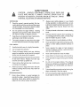
OWNER'S
MANUAL
MODEL NO.
536.797510
Caution:
Read and Follow
All Safety Rules
and Instructions
Before Operating
This Equipment
9 INCHEDGER
•
°
•
°
°
SEA____RS,
ROEBUCK
Pa_ No 30B408B
2.5 HORSEPOWER
Assembly
Operation
Maintenance
Service and Adjustments
Repair Parts
AND CO., Chicago,
IL 60684 U.S.A.
SAFETY
CAUTION:
PLACE
ALWAYS
WIRE
DISCONNECT
WHERE
IT CANNOT
PREVENT
ACCIDENTAL
STARTING
PORTING,
ADJUSTING
OR MAKING
BEFORE USE
=
Read
RULES
SPARK
CONTACT
WHEN
manual
carefutly.
Do not operate the edger without
wearing
adequate outer garments° Wear footwear that
will improve footing on slippery surfaces,
_'
Keep the area of operation
particularly small children
e
Thoroughly
inspect the area where the edger
is to be used and remove all foreign objects_
•
Use an approved
o
Check fuel supply before each use, allowing
space for expansion as the heat of the engine
and/or
a running
o
OPERATING SAFETY
Never allow children or young teenagers
to
operate the edger_ Keep them away while it is
operating
Never allow adults to operate the
edger/trimmer
without proper instruction,
glasses
or eye shields
e
Neveroperatethe
plates, or other
place.
caution
to avoid slipping
or falling
edger without proper guards,
safety protective
devices in
Never operate the edger at high transport
speeds on slippery surfaces. Look behind and
use care when backing.
e
Never allow bystanders
•
Keep children
near the edger.
and pets away while operating
Never operate the edger without good visibility
or light.
®
Do not run the engine
indoors,
The exhaust
fumes are dangerous
(containing
CARBON
MONOXIDE,
an ODORLESS
and DEADLY
GAS),
or hot engine.
Never store fuel or edger with fuel in the tank
inside a building where fumes may reach an
open flamen
safety
Exercise
with extreme care. Never
the fuel tank cap or add fuel to
wear
e
fitl fuel tank indoors., Replace fuel tank cap
securely and wipe up spilled fuel,.
Never remove
Always
Exercise extreme caution when operating on
or crossing gravel drives, walks, or roads° Stay
alert for hidden hazards or traffic,
container.
Fill fuel tank outdoors
TRANS-
o
fuel with care; it is highly flammable.
sun can cause fuel to expand.
SETTING-UP,
TO
Do not put hands or feet near or under rotating
parts.
FUEL SAFETY
Handle
PLUG
e
clear of all persons,
and pets.
o
SPARK
AND
during operation or while performing
an adjustment or repair to protect your eyes from foreign objects that may be thrown from the
edger.
Be thor-
oughly familiar with the controls and the proper
use of the edger. Know how to stop the edger
and disengage the controls quickly,
o
WIRE
REPAIRS,
o
the owner's
PLUG
=
Take all possible precautions when leaving
edger unattende&
Stop the engine.
the
o
Do not overload the edger capacity by attempting to edge too deep at too fast a rate.
SAFETY
RULES
SAFE STORAGE
•
Always refer to the owner's manual storage
section for important details if the edger is to
be stored for an extended period.
•
Never leave the edger with fuel in the fuel tank
inside a building where ignition sources are
present such as water and space heaters,
ctothes dryers, and the like. Allow the engine to
cool before placing in any enclosure°
•
Keep the edger in safe working
condition.
Check all fasteners
at frequent intervals for
proper
Stop the btade whenever you leave the operating position° Also, stop the engine and disconnect the spark plug wire before unclogging
the blade and when making any repairs, adjustments, or inspections.
•
When cleaning, repairing, or inspecting, shutoff the engine and make certain all moving
parts have stopped.
•
Never attempt to make any adjustments while
the engine is running (except when specifically
recommended by the manufacturer).
tightness.
REPAIR1ADJUSTMENTS
•
•
SAFETY
After striking a foreign object, stop the engine
(motor). Remove the wire from the spark plug,
and keep the wire away from the plug to
prevent accidental starting. Thoroughly inspect
the edger for any dam age, and repair the damage before restarting and operating the edger.
•
If the edger should start to vibrate abnormally,
stop the engine (motor) and check immediately for the cause, Vibration is generally a
warning of trouble
LOOK FOR THIS SYMBOL TO POINT OUT
IMPORTANT SAFETY PRECAUTIONS°
IT
MEANS--ATTENTION!f!
BECOME ALERT!!!
YOLIR SAFETY IS INVOLVED,
3
CONGRATULATIONS
on your purchase of a Sears
Craftsman Edger. tt has been designed, engineeredand
manufactured to give you the best possible dependability and performances.
Should you experience any problem you cannot easily
remedy, please contact your nearest Sears Service Center/Department. We have competent, well-trained technicians and the proper tools to service or repair this unit°
Please read and retain this manual, The instructions will
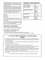
PRODUCT
HORSE
SPECIFICATIONS
POWER:
DISPLACEMENT:
9.06 cu. in.
(148 c.c)
GASOLINE
"1.0 qt.
Unleaded
CAPACITY:
enable you to assemble and maintain your edger properlyo Always observe the "SAFETY RULES."
(Regular)
LUBRICATION:
MODEL
NUMBER
DATE OF
PURCHASE
SPARK
THE MODEL NUMBER WILL BE FOUND ON A
DECAL ON THE FRAME OF THE EDGER BEHIND
THE ENGINE,
2.5 hp
PLUG
21 oz.
SAE- 10W-30
:
GAP °030 in,)
Champion
CJ -8 or
Equivalent
YOU SHOULD RECORD BOTH MODEL NUMBER
AND DATE OF PURCHASE AND KEEP IN A SAFE
PLACE FOR FUTURE REFERENCE
MAINTENANCE
AGREEMENT
A Sears Maintenance Agreement is available on this
product Contact your nearest Sears Store for details
CUSTOMER
RESPONSIBILITIES
• Read and observe the safety rules
• Follow a regular schedule in maintaining, caring for and using your edger.
o Follow the instructions under "Maintenance" and "Storage" sections of this owner's manual.
ONE YEAR LIMITED WARRANTY
EDGER
ON CRAFTSMAN
For one year from the date of purchase, when this Craftsman Edger is maintained, lubricated and tunedup according to the instructions in the owner's manual, Sears will repair, free of charge, any defect in material and workmanship
If this Craftsman Edger is used for commercial or rental purposes, this warranty applies for only 90 clays
from the date of purchase..
This warranty does not cover the following:
o Expendable items which become worn during normal use, such as spark plugs, etc
•
Repairs necessary because of operator abuse or negligence, including bent crankshafts and the failure
to maintain the equipment according to the instructions contained in the owner's manual
WARRANTY SERVICE IS AVAILABLE BY RETURNING THE CRAFTSMAN EDGER TO THE NEAREST
SEARS SERVICE CENTER/DEPARTMENT
IN THE UNITED STATES. THIS WARRANTY APPLIES
ONLY WHILE THIS PRODUCT IS IN USE IN THE UNITED STATES.
This warranty gives you specific legal rights, and you may also have other rights which may vary from
state to state
SEARS, ROEBUCK AND CO. Department 731CR-W Sears Tower, Chicago, IL. 60684
i iillllllll
illlllllllllllllllllllllllllll
TABLE OF CON ENTS
i
LJL IIIIII_1,U,IIIll,,II
SAFETY RULES ........................................
2,3
PRODUCT SPECIFICATIONS
...................... 4
CUSTOMER
RESPONSIBILITIES
............... 4
WARRANTY ..................................................
4
TABLE OF CONTENTS ................................
5
ASSEMBLY ............. ...................................
5-7
OPERATION
........... _................................
8-11
iiii ii
MAINTENANCE
.......................................
t2-13
SERVICE AND ADJUSTMENTS
........... t 4-I 5
STO RAG E ........................................................
16
TROUBLE SHOOTING .................................... 17
REPAIR PARTS
(EDGER) .................... t 8-22
REPAIR PARTS (ENGINE) ..................... 23-25
PARTS ORDERINGISERVtCE
.... _Back Cover
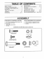
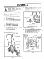
ASS
CONTENTS
OF SHIPPING
CARTON
1 - 9 inch Edger completely assembled except for the
control rod, handles and wheels,
1 - Control Rod
TOOLS
REQUIRED
FOR ASSEMBLY
2 - 3/8 inch Wrenches (or adjustabre wrenches)
2 - 1/2 inch Wrenches (or adjustable wrenches)
1 - Pair Pliers
1 - Owner's Manual (Not Shown)
1 - Parts Bag
CONTENTS
2- 5t16-18
OF PARTS
BAG (shown
actual
size)
x 1-1t2 inch
Hex Head Screws
6 - 5/16d8
Hex Nuts
2 - Hair Pins
4 - 5116-18 X 5/8 inch Hex
Head Wide Flange Screws
2 - Spacers
3 - 3t8-16 X 1.390 Inch
Shoulder Bolls
3,3/8.16
Wide Flange
Hex Head
Locknuts
ASSE
,,=_
............
i
i=1
q
,u i,=,11=1
i iiii,
ii
,
GLASSES OR EYE SHIELDS WHILE
CAUTION:
ALWAYS WEAR SAFETY
ASSEMBLING EDGER.
BLY
qlll, l,ii,i
i
...................
iii
i
, lil, i
Attach the front wheel, with the ribs to the outside,
to the edger (See Fig 2) with a 3/8-16 x 1 390 inch
shoulder bolt and 3/8-16 hex wide flange lock nut
(found in parts bag),,
Figure 1 shows the edger completely assembled,
Reference to the right and left hand side of the edger is
from the operator's position behind the unit
WHEEL
TO REMOVE
EDGER
FROM CARTON
_'
Open the top of the carton
•
Remove the packing material from the cation
=
Remove the plastic parts bag from the carton
•
Remove the control rod from the carton.
•
Remove the handles from the carton.
e
Cut down all four corners of the carton
TO ASSEMBLE
3tS-16X1o390]NCH
SHOULDER BOLT
318.16 HEX NUT
SPACER
(NOT USED ON FRONT WHEEL)
THE EDGER
VIEW FROM RIGHT SIDE OF UNIT
=
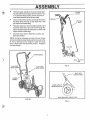
Attach each rear wheel, with the ribs to the outside,
to the edger (See Fig 2) with a 3/8-16 x 1,390 inch
shoulder bolt, spacer and 3/8-16 hex wide flange
lock nut (found in parts bag)
UPPER
HANDLE
FIG. 2
Place the lower handle inside the edger frame (See
Fig. 3A) and secure in place with four (4) 5/16-"
hex head wide flange screws and four (4) 5/_
hex head bcknuts (found in parts bag).
5t16-18 HEX
CLUTCH
LEVER
HEAD WIDE
FLANGE
LOW ER
/HANDLE
_
5t16-18 HEX
SCREWS
LOWER
HANDLE
STARTER
HANDLE
i
BLADE
GUARD
FRAME
FIG. 3A
BLADE
FIG_ 1
ASSEMBLY
i i
@
, ill i uu ull um Hul
•
Place the upper handle on the lower handle (See
Fig. 3B) and secure in place with two (2) 5/16-18 x
1-1/2 inch hex head screws and two (2) 5/16-18
head head Iocknuts {found in parts bag)
•
Insert one end of the control rod through the hole in
the clutch lever (See Fig° 4) and attach with a hair
pin (found in the parts bag)°
o
Place the clutch lever in the first depth selection and
insert the other end of the control rod through the
hole in the quill support arm (See Fig 4) Attach with
hairpin (found in parts bag).
o
Move the clutch lever to NEUTRAL position and
latch into position,
,t
CLUTCH
LEVER
HAIR PIN
CONTROL
ROD
NOTE: It may be necessary to loosen the four screws
and nuts holding the lower handles to the frame (See Fig.,
5). Pry up (forward) on the handles to allow the clutch
lever to freely enter the NEUTRAL position, Retighten
nuts and screws.
HAIR PIN
UPPER HANDLE
I
)
QUILL SUPPORT
ARM
5116-18HEX
HEAD SCREW
FIGo 4
5116-18 HEX
SCREW
LOWER
HANDLE
LOWER
HANDLE
RIGHT SIDE
LOWER
HANDLE
VIEW FROM RIGHT SIDE OF UNIT
FIG. 3B
FIG. 5
@
7
OPERATION
i,i,
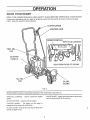
KNOW YOUR EDGER
READ THIS OWNER'S
MANUAL
AND SAFETY
RULES BEFORE
OPERATING
YOUR
EDGER,
Compare the illustrations with your edger to familiarize yourself with the location of various controls and adjustments Save this manual for future reference,
CLUTCH
LEVER
:ONTROL
CHOKE
ROD
CONTROL
THRO'I-rLE
CONTROL
FUEL
CAP
STARTER
HANDLE
VIEW FROM
OIL FILL
CAP
REAR OF ENGINE
BLADE
GUARD
FIG. 6
SEARS EDGER conforms to ttie safety standards of the Underwriters Laboraties Inc
THRO3-FLE CONTROL
speed.,
- Used to control the engine
CHOKE CONTROL - Used to start the engine
STARTER HANDLE - The engine on this edger is
equipped with an easy pull recoil starter.
CLUTCH LEVER - Used lo start and stop the blade and
control the depth of cut
BLADE GUARD - Used to prevent stones or other material from being throw_ at lhe operator,
OPERATION
The operation of this edger can result in foreign objects being thrown into the eyes,
which can result in severe eye damage. Always wear safety glasses or eye shields
while operating the edger.
We recommend standard safety gtasses or Wide Vision Safety Mask for over your
glasses
©
CAUTION:
KEEP AWAY
ROTATING BLADE. THE
CAUSE INJURY.
FILL/ADD
FROM
BLADE
THE
CAN
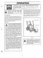
OIL:
The engine on this edger was shipped with little or no oil.
Add oil before you start the engine, Place the edger on a
level surface Remove the oil fill cap (Fig 7). Fill the
engine crankcase to point of overflowing using about 2I
ounces (1_It4 pts) of Sears SAE !0W-30 motor oil or
equivalent
Reinstall the oil fill cap
FILL
Never use engine or carburetor cleaner products in the
fuel tank or permanenl damage that may occur.
FUEL FILL CAP
GAS:
, ,,
.b
Fill the fuel tank (See Fig 7) wilh clean, fresh, unleaded
grade automotive gasoline. Be sure that the container
you pour the gasoline from is clean and free from dust or
other foreign particles. Never use gasoline that may be
stale from long periods of storage in the container
,, ,,,,
AND CAUTION MUST BE USED WHEN
CAUTION: GASOLINE tS FLAMMABLE
HANDLING OR STORING IT. DO NOT
FILL FUEL TANK WHILE EDGER IS RUNNING,
HOT, OR WHEN EDGER IS IN AN ENCLOSED
AREA_ KEEP AWAY FROM OPEN FLAME, ELECTRICAL SPARK, AND DO NOT SMOKE WHILE
FILLING THE FUEL TANK. NEVER FILL FUEL
TANK COMPLETELY; BUT FILL THE TANK TO
WITHIN 1/4 - 1/2 INCH FROM THE TOP TO PROVIDE SPACE FOR EXPANSION OF FUEL. ALWAYS FILL FUELTANK OUTDOORS AND USE A
FUNNEL OR SPOUT TO PREVENT SPILLING°
MAKE SURE TO WIPE UP ANY SPILLED FUEL
BEFORE STARTING THE ENGINE.
STORE GASOLINE IN A CLEAN, APPROVED
CONTAINER, AND KEEP THE CAP IN PLACE ON
THE CONTAINER° KEEP GASOLINE IN A COOL,
WELL VENTILATED PLACE; NEVER IN THE
HOUSE. NEVER BUY MORE THAN A 30 DAY
SUPPLY OF GASOLINE TO ASSURE VOLATILITY GASOLINE IS INTENDED TO BE USED AS A
FUEL FOR INTERNAL COMBUSTION ENGINES;
THEREFORE_ DO NOT USE GASOLINE FOR ANY
OTHER PURPOSE. SINCE MANY CHILDREN LIK E
THE SMELL OF GASOLINE, KEEP IT OUT OF
THEIR REACH BECAUSE THE FUMES ARE DANGEROUS TO INHALE, AS WELL AS BEING EXPLOSIVE.
OIL FiLL CAP
FIG. 7
CAUTION: NEVER FILL THE GAS TANK
WHILE THE ENGINE IS RUNNING OR HOT.
IMMEDIATELY WIPE OFF ANY SPILLED
GASOLINE BEFORE ATTEMPTING TO
START THE ENGINE.
mmum, mumUulunUullUUUlUnllUl
uHII
i i
OPERATION
PRE-USE
CHECK OF CONTROLS
®
All controls should be checked for proper function before
servicing or starting the engine
o
•
Move the clutch lever into all five (5)positions in the
selector ptateo Make sure the clutch lever snaps into
all five (5) holes°(Fig. 6)
speed, push the throttle control lever up.
TO START THE ENGINE
®
Before starting the engine, be sure you have read and
understood allthe instructio ns on the preceding pages+The
edger is equipped with a recoil starter. The operation of
the engine is controlled by the throttle control lever+
Pull the clutch lever all the way back (or up to the
rearmost hole) to raise and disengage the blade+
o
Move the throttle control lever (See Fig° 6) to the
FAST position.
•
Move the choke control lever (See Fig. 6) to the Full
choke position+
To start engine, grasp the starter handle firmly your
right hand.
®
Hold handle firmly with your left hand°
o
Pull up sharply on the recoil starter handle.. DO NOT
allow the starter rope to snap back, let it rewind
sJowly while holding the starter handle
o
O
Start the engine and move the clutch lever forward
(or down) to engage the cutting blade+
Select the edging depth you need There are 4
selections up to 2-3/4 inches deep.
IMPORTANT:
IFVERY DEEP EDGING IS REQUIRED,
WE RECOMMEND THATA SHALLOW
CUT BE MADE FIRST, THEN CUTS
AT GREATER DEPTHS UNTIL THE
DESIRED DEPTH IS OBTAINED,
KEEP THE EDGER CLEAN
Always remove the dirt and debris from the edger after
each use+ Check for loose or damaged parts after each
use. Tighten any loose fasteners+ Check the controls
often to make sure they are functioning properly_ See the
Pro-Use Check of Controls paragraph In the Operation
section of this manual.
NOTE: It will take a few pulis on the startet: handle to feed
gas from the fuel tank to the carburetor.
If any adjustments are required, see the Adjustments/
Repairs section of this manual If any parts are worn or
damaged, replace immediately+ Contact the nearest
SEARS Store or Service Center for proper originat parts,
as shown in the Repairs Parts section of this manual.
Make repairs as instructed in Adjustments/Repairs
section of this manual,
DOORS OR IN A POORLY VENTILATED
CAUTION: NEVER RUN THE ENGINE INAREA. ENGINE EXHAUST CONTAINS
CARBON MONOXIDE, AN
GAS AND DEADLY GAS.
To stop the engine, make sure the clutch lever is all
the way back (or up) and move the throttle control
lever to the STOP position+
EDGING OPERATION
NOTE: A warm engine should not need to be choked.
e
o
control
engine
To decontrol
NOTE: The cutting blade speed is controlled by the
engine speed- To reduce the cutting bIade speed, push
down on the throttle control lever+ To increase the blade
Return the clutch lever to the rearmost hole in the
selector plate+
e
When the engine starts, move the throttle
lever to the FAST position+ To increase the
speed, push the throttle control lever upcrease the engine speed push the throttle
lever down.
ODORLESS
KEEP HANDS, FEET, HAIR AND LOOSE
CLOTHING AWAY FROM ANY MOVING
PARTS ON THE ENGINE OR EDGER,
WARNING - AVOID THE MUFFLER AND
SURROUNDING
AREAS (SEE FIG+ 6).
TEMPERATURES MAY EXCEED 150 ° F+
10
inunuluiull
i
i,
MAINTENANCE
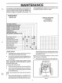
following Maintenance Check List is supplied to assist
the operator properly maintain the edger.
The warranty on this edger does not cover items that
have been subjected to operator abuse or negligence. To
receive full value from the warranty, the operator must
maintain the edger as instructed in this manual. The
MAINTENANCE
CHECK
LIST
SERVICE
RECORD
FILL IN DATES
AS YOU COMPLETE
REGULAR SERVICE
BEFORE STORAGE
BEGINNING EACH SEASON
EVERY
25HOURS
OFUSE ..................
EVERY
10HOURS
OFUSE
EVERY 5 HOURS OF USE
FREQUENTLY
BEFORE EACH USE
AFTER FIRST 2 HOURS OF USE
Check Engine Oil Level
O
Change Engine Oil
O
O
Tighten All Screws and Nuts
Check Blade Wear/Damage
O
@ @
O
O
O
@
@ @
Replace Air Cleanei Fiiier
Check Spark Plug
O
Check Drive Belt
@
@
Lubricate all Pivot Points
Lubiicate Wheei Axles ........
@
@
Sears SAE 30 motor oil or equivalent may be used
as an acceptable substitute. Reinstall the oil fill cap
and tighten securely.
LUBRICATION
e
Apply light machine oil after each 25 hours of use to
all moving parts, particularly the wheels°
o
The oil in the crankcase must be changed after the
first 2 hours of operation and after each 25 hours of
use thereafter.
NOTE: The quill assembly bearings are factory sealed
and will require no lubrication_
•
Reconnect the spark plug wire on the spark plug
i
NOTE: If the edger is being used in sandy or dusty
areas, change the oil more frequently to prevent
premature engine wear.
To change the crankcase
O
VIEW FROM REAR
-!
oil:
®
Disconnect the spark plug wire from the spark plug..
o
Remove the oil drain plug (See Fig. 8) and drain the
oil into a flat pan. After draining all the oil, reinstall
the oil drain securely.
NOTE: The oil will drain more freely when the engine is
warm.
e
Remove the oittill cap (See Fig 7), and fillthe crankcase to the point of overflowing, using about 1-1/4
pints of Sears SAE 10-W30 motor oil or equivalent,
OIL DRAIN PLUG
FIG. 8
tl
i i
i ll,i
i,,,i,,i
i,i
iu,J.i.
TENANCE
ii
AIR CLEANER
ii ,i
,,
IIMI
I
, I,l,,I
MAINTENANCE
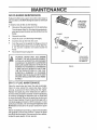
Replace the filter once a year; more often under dusty or
dirty conditions. DO NOT attempt to clean or oil the air
filter.
TURN COVER
TO THE LEFT
(COUNTERCLOCKWISE)
TO REMOVE
To install a new air filter, do the following:
o
Disconnect the spark plug wire from the spark plugo
Turn the cover (See Fig, 9) to the left (counterclockwise) and remove the cover and the air filter from the
flange..
e
Discard the air filter.
•
Clean the cover and the flange thoroughly
o
Insert the new air filter into the cover.
®
Push the cover firmly against the flange and turn it
to the right (clocte,vise) as far as it will go (See Fig
9. Be sure the retainers are locked around the
FLANGE
FILTER
RETAINER
COVER
SLOT
flange.
o
TAB
Reconnect the spark plug wire.
_
TURN COVER
TO THE RIGHT
(CLOCKWISE)
TO REMOVE
WITHOUT THE AIR CLEANER ELEMENT
CAUTION:
NEVER RUN THE ENGINE
IHSTALLED. A DEFECTIVEAIR CLEANER
CAN RESULTtN LOSS OFEHGINEPOWER
AND CAN CAUSE EXCESSIVE WEAR OR
DAMAGETO THE ENGINE COMPONENTS
tF DIRT OR DUST IS PERiv]ITTED TO ENTER THE ENGfHE THROUGI] THE CARBURETOR, A DAMAGED AIR CLEANER_
OR ONE THAT IS CLOGGED WiTH DUST
OR DIRT SHOULD BE REPLACED IMMEDIATELY,
FIG. 9
SPAR < PLUG MAINTENANCE
Clean the spark plug and reset the gap periodically.
Clean the area around the spark plug base, before
removal, to prevent dirt from entering into the engine.
Replace the spark plug if the electrodes are pitted or
burned or if lhe porcelain is cracked.. Clean the spark plug
by carefully scrapping the electrodes (do not sand blast
or use a wire brush). Be sure the spark plug is clean and
free of foreign material. Check the electrodes gap with a
wir e feeler gauge and reset to ,,035 if necessary. If a new
spark pIug is needed, refer to the Engine Operation and
Maintenance manual for the proper replacement spark
plug
Before reinstalling the spark plug, coat the threads lightly
with graphite to insure easy removal,, Tighten the spark
plug firmly into the engine° If a torque wrench is available,
torque the spark plug to 15 foot- pounds.
12
nl i nl ..,,,
i,i u i, i , i
i i. HH. HH.....
SERVICE AND ADJUSTMENTS
i
..................................
_,.i u .,ll,ll.
CAUTION:
DO NOT ATTEMPT
TO
SHARPEN THIS BLADE. YOU COULD
CAUSE DAMAGE TO THE BLADE WHICH
COULD RESLILT IN BREAKAGE AND
POSSIBLE
USER OR BYSTANDER
INJURY,
CAUTION: ALWAYS STOP THE ENGINE
AND DISCONNECT THE SPARK PLUG
WIRE BEFORE MAKING ANY REPAIRS
TO THE EDGER.
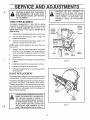
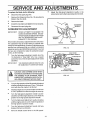
V-BELT REPLACEMENT
Your edger is equipped with a V-bett made of a special
compoun& If the belt becomes worn or breaks, replace
it with an original equipment
belt as shown in the
Repair Parts section of this manual. NEVER USE A
SUBSTITUTE.
•
Disconnect the spark plug wfre from the spark plug
o
Pull the clutch lever back (or up) to release the
tension from the bell
o
Remove the screws from the engine pulley cover
(See Fig° 10) and remove the cover,
ENGINE
PULLEY
COVER
ENGINE
PULLEY
COVER
SCREWS
ENGINE
PULLEY
NOTE: Make sure the spacer on the screw does not
become lost,
e
J
Remove the front screw securing the belt guide
(See Fig. 10) to the engine, Then loosen the rear
screw and swing the belt guide away from the belt,
•
Remove the three (3) screws from the belt guard
(See Fig, 11).
e
Remove the belt from the engine and quill assembly
pulIey&
®
Install the new belt in the reverse order of removal
o
Secure the belt guide loosened earlier_
e
Reinstall the engine pultey cover and reconnect the
spark plug wire.
BLADE
V-BELT
FRONT
SCREW
BELT
GUIDE
FIG. 10
REPLACEMENT
The cutting blade is subject to wear and damage such as
nicks and dents. This will not generally effect its function
This blade is specially designed to not require sharpening DO NOT ATTEMPT TO SHARPEN THIS BLADE
The blade is reversible If the nicks and dents are excessire, remove the blade, turn it around and reinstall,, This
will provide a fresh cutting edge If worn or damaged the
btade should be replaced,
BELT
GUARD
CAUTION: WHEN REMOVING OR TIGHTENING THE BLADE NUT, ALWAYS USE
THE METHOD SHOWN IN FIGURE 12_
THE HOLDING WRENCH MUST ALWAYS
BE POSITIONED BEHIND THE CUTTING
BLADE. NEVER USE THE LOCKNUT ON
THE PULLEY END, DAMAGE TO THE
SHAFT OR BEARINGS COULD RESULT.
BELT
GUARD
SCREWS
FIG. 11
13
REAR
'SCREW
f.
= .,.,.,,=
..,
= =
==.,.==
SERVICE AND ADJUSTMENTS
=, .,.,,,,,,,,,,,,,,,
•
To replace the blade, do the following:
•
Disconnect the spark plug wire,.
=
Remove the flange nut (See Fig. 12) securing the
blade to the drive shall
e
Remove the blade,.
o
Install the new blade and tighten the nut securely,
•
Reconnect the spark plug wire.
CARBURETOR
IMPORTANT:
=,1,,
Adjust the idle-speed adjustment needle in the
same manner as the high-speed adjustment needle°
TIGHTENING
ADJUSTMENT
NEVER ATTEMPT TO CHANGE THE
MAXIMUM ENGINE SPEED., EXCESSIVE SPEEDS CAUSEDBY BY-PASSING THE GOVERNOR CAN CAUSE
DAMAGE TO THE ENGINE.
WRENCH
Never make unnecessary adjustments to the carburetor_
The carburetor was set at the factory to operate effeciently for most applications° However, if adjustments are
required, we recommend that you contact a competent
repairman such as at a SEARS Service Center. If you feel
that you are competent to make the carburetor adjustments, do the following:
e
=,
FLANGE
NUT
BLADE
FIG_ 12
Turn the high-speed adjustment needle (see Fig.
13) clockwise to "finger tight" only. Use a regular
screwdriver to turn the idle speed adjustment needle
clockwise
IMPORTANT:
THE NEEDLES AND/OR SEATS CAN
BE DAMAGED IF OVERTtGHTENED
==,
HiGH SPEED
ADJUSTMENT
NEEDLE
,,,,,, ,,,,, ,,,,,,,,,
CAUTION: USE EXTREME CARE WHEN
MAKING ADJUSTMENTSTHAT REQUIRE
THE ENGINE TO BE RUNNING, KEEP
HANDS, FEET, HAiR AND LOOSE CLOTHING AWAY FROM ANY MOVING PART.
FIG. 13
1,, 1, _J=,.l=,
Turn the high-speed and the idle-speed adjustment
needles counterclockwise one (1) turn, This adjustment will allow the engine to be started..
o
Start lhe engine and move the throttle control lever
to FAST position and allow the engine to warm upo
o
Turn the high-speed adjustment needle counterclockwise until the engine starts to cut off, Note the
position of the high-speed adjustment needle.
•
Turn the high-speed adjustment needle c!ockwise
until the engine starts to cut off. Note the position of
the high-speed adjustment needle..
•
Turn the high-speed adjustment needle half way
between the two cut off points
•
Move the throttle control lever to the idle speed.
"
14
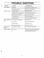
TROUBLE
"b
TROUBLE
SHOOTING
CAUSE
CORRECTION
Stale fuel
Drain fuel tank. Fill wilh fresh fuel
i
Difficult
starting
ii ,,,m
Clean and re-gap spark plug
Defective spark plug ,.
Engine runs erratic
i
Clogged fuel filter
Replace fuel filter.
Blocked fuel line or empty fuel tank
Clea n fuei tiile i c,h eck'gas tank. ' .....
Carburetor out of adjustment
Have carburetor adjusted
Fouled spark plug
Clean and adjust gap.
-
"
Tap dean or replace air c{eaner,
Ctogged air cleaner
i
Jammed due to foreign object
Clear obstruction
Loose blade
Tighten blade retaining nut.
Defectwe V-belt
Replace the V-belt
Defective quill bearings
Replace the bearings
Blade fails to cut
properly
Damaged or worn blade
Reverse blade or replace blade
Excessive
Loose parts
Stop engine immediateJy; tighten all bolts If
vibration continues, take the unit into the
nearest SEARS Service Center
Cutting
turn
blade fails to
vibration
15
STORAGE
[
_ILJJJJ J ii_JJJl _ _J •
_IJ-_JJLWII_LIL
You can keep your engine In good operating
tion during storage by:
EDGER
INDOORS OR IN AN ENCAUTION:
NEVER STORE YOUR
CLOSED, POORLY VENTILATED AREA
IF GASOLINE REMAINS IN THE TANK. FUMES
MAY REACH AN OPEN FLAME_ SPARK OR PI"
LOT LIGHT FROM A FURNACE, WATER HEATER,
CLOTHES DRYER, CIGARETTE, ETC.
•
•
iii L Jii
JLui,,_Jil_
To prevent engine damage ( if edger is not used for more
than 30 days) follow the steps below°
ENGINE
•
If you do not want to remove gasoline, a fuel
stabilizer (such as Sears Craftsman fuel stabilizer
No..33500) may be added to any gasoline Iett in the
tank to minimize gum deposits and acids_ If the tank
is almost empty, mix stablilizer with fresh gasoline
in a separate container and add some to the tank.
ALWAYS FOLLOW INSTRUCTIOHS ON STABI-
Changing oil.
Lubricating the piston/cylinder area. This can be
done by first removing the spark plug and squirting
clean engine oil into the spark plug hole Then cover
the spark plug hQte with a rag to absorb oil spray_
Next, rotate the engine by pulling the starter two or
three times_ Finally, reinstall spark plug and attach
spark plug wire_
Clean lhe edger thoroughly; remove all debris and
wipe the unit dry.
Gasoline must be removed or treated to prevent gum
deposits from forming In the tank, fitter, hose, and
carburetor during storage. Also during storage, alcohol blended gasoline that uses ethanol or methanol (sometimes called gasohol) attracts water. It acts
on the gasoline to form acids which damage the
engine.
To remove gasoline, run the engine until the tank is
empty and the engine stops.
•
•
f
L
EDGER STORAGE
STORAGE
o
condi-
Inspect the edger for worn or damaged parts and
tighten all loose hardware
Oil all points described in the Lubrication
paragraph in the Maintenance section of this manual
Store the edger in a protected area and cover for
additional protection
IMPORTANT:
A YEARLY CHECKUP OR TUNEUP BY
A SEARS SERVICE CENTER tS A
GOOD WAY OF INSURING THAT
YOUR EDGER WILL PROVIDE
MAXIMUM PERFORMANCE FOR
THE NEXT SEASON.
LIZER CONTAINER. THEN RUN ENGINE AT
LEAST 10 MINUTES AFTER STABILIZER
IS
ADDED TO ALLOW MIXTURE TO REACH CARBURETOR. STORE EDGER IN A SAFE PLACE.
SEE WARNING ABOVE.
•
Store the edger in the wheels-down, operating
position. If the edger is stored in any other position,
oil from the crankcase could enter the cylinder,
causing a service problem_
\
16
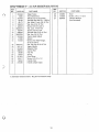
EPA!
9
PA
C AFTSMAN
EDGER
ODEL 536=797510
.©
17
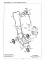
CRAFTSMAN
9"-
2.5 H.P. EDGER 536.797510
17
/5
2O
Re{
On
Ne
Page
32
20
Ref No 5
On Page 20
4
!
6
18
NOTE: ALWAYS USE ORIGINAL
EQUIPMENT PARTS Use of service/
ALL UNNUMBERED
ITEMS ABE INTERCHANGEABLE
WITH OPPOSITE SIDE
replacement parts other than original
parts may void your warranty
18
CRAFTSMAN
REF_
NO.
©
PART NO.
1
2
3
4
5
6
7
8
9
10
11
12
13
t4
313248
6950
312409
23763
45171
120376
122007
9424215
122040
309902
9413534
312548
21882
51333
'15
16
17
18
19
20
21
22
23
24
9413447
310147
310623
308245
36368
25644
311670
122017
56924
310055
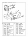
9"-
2.5 H.P. EDGER 536.797510
REF.
NO.
PART NAME
25
26
27
Edger Frame
Front Wheel Arm
Wheel and Tire Assembly
Shoulder Bolt 3/8-16 x 14390 In
PART NO.
310053
121926
308408
PART NAME
Stud
• Screw, 1/4-2 x 1-1/2 In
Owner's Manual
(Not Illustrated)
Nut, Wide F1Lock, 3/8-16 Thd
* Nut, Hex, 5/16-18 Thd
* Screw, 5/16-18 x 3/4 In
Nut, Lock, 1/4-20 Thd
Screw, 5/16-18 x 3/4
Shoulder Bolt, 5/16-18 "f
* Nut, Hex, 3/8-16 Thd
Decal, Height Adjust
Spacer
* Screw, Hex Wide Flang_
5116-18 x 518 In,
Nut, Reg Hex 5116-18 TI
Upper Handle
Selector Plate
Control Rod
Hair Pin
Spring
Lever Strap
* Screw, 5/16-18 x 1 In
Handle, Grip
Handle, Depth Adjust
(*) ,Standard Hardware Items - May_Be Purchased Locally
©
19
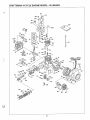
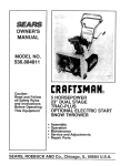
CRAFTSMAN
9" - 2.5 H.P. EDGER 536.797510
9
29
19
20
18
t8
15
t4
23
15
16
REF.
NO.
I
i
PART NO.
REF.
NO.
PART NAME
2
3
4
5
32689
102580
313011
309448
312165
Engine Pulley
Set Screw, 5/16-18 x 1/4 In
Screw and Washer Assembly
Belt Guide
Engine, Craftsman 4-Cycle
Model No 143 804082
6
7
8
9
10
11
12
13
14
15
16
17
18
19
412281
308237
53407
430464
309300
181624
308254
308262
274654
305634
411666
8869
43846
48697
Spring Pin
Spacer
Spacer
Screw, HHC, 5/16-18 x 3-3/4 In
Engine Pulley Cover
Screw, HHC, 5/16-24 x 3 In
Shoulder Bolt, 3/8-16 Thd
Belt Guard
Locknut, I/2-20 Thd
Pulley, Half
Screw, Tap, #10-16 x 1/2 In
V-Bett
Ball Bearing
Drive Shaft
20
21
22
23
24
25
26
27
28
29
3O
31
32
33
34
35
36
2O
PART NO,
120371
4935
996418
308349
9413447
35075
309301
313247
9413534
455999
308502
46023
308540
49998
308243
309360
312564
PART NAME
Nut, 1/2-20 Thd
Shield Washer
Flatwasher
Quill Arm Assembly
Nut, 5/16-18 Thd
Hi-Pro Key
Compression Spring
Blade Guard
Nut, 5/16-18 Thd
Carriage Bolt, 5/16-18 x 5/8 In
Blade
Nut, Wide Flange, 1/2-20 Thd
Quill Support Assembly
Flatwasher
Deflector
Strap
Decal, Blade Cover
,f
a
"k.
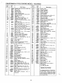
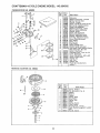
CRAFTSMAN
4-CYCLE
ENGINE MODEL: 143.804082
131
l
_t
O
21
/
/
CRAFTSMAN
Ref
No.
1
2
14
15
18
17
16
19
20
25
25P
25B
26
30
40
4O
4O
41
41
41
42
42
42
43
45
46
48
49
5O
69
7O
72
75
80
81
82
83
84
86
89
90
92
93
100
t02
103
110
119
12o
125
125
126
126
130
131
f32
135
Part
No,
4-CYCLE
ENGINE MODEL:
143.804082
Ref°
P_tName
Part
No.
No,
34708A
26727
28277
31334
31336
31335
650548
34593
32600
t33342
t650139
t30332
650561
172
173
174
178
t79
180
181
182
184
t85
186
208
31672
31673
"27234A
27686
31410
34146
35350
650128
29752
30593
33341
650884
6201
"31688A
34597
31341
t33838A
203
2O4
206
215
223
224
238
31342
650549
610973
32410
8£-43451
"32649A
6_32
239
245
249
25O
2_
261
274
275
277
284
284A
*34338
35066
35797
35065
35585
29212
"30081A
30996
650493
30997
650665
285
287
29O
292
298
34694
65O884
29774
2646O
65O665
150
151
Cylinder Assy. (IncL Nos. 2, 20 8- 72)
Pin, Dowel
Washer, Flat
Rod, Governor
Lever, Governor
Clamp, Governor lever
Screw, Hex washer hdo, 8-32 x 5/16
Spring, Extension
Seal, Oil
Baffle, Blower housing
Screw, Fil. hdo Seres, 8-32 x 1/2
Locknut,
Hex "Keps',
8-32
Screw, Hex washer hd. Durlok, 1/420
x 518
3473O
Crankshaft
Assyo
34514
Piston, Pin 8. Ring Assy. (Std)
(incl.
Nas,,41, 42 8- 43)
34515
Piston, Pin _ Ring Assy. (.010 oversize) (lncL Nos. 41, 42 8. 43)
34516
Piston,
Pin 8 Ring Assy. (.020 oversize) (Incl. Nos. 41, 42 8 43)
325388
Piston 8 Pin Assy. (Std,) (Incl Noo 43)
32548B Piston E_ Pin Assy. (010 oversize)
(IncL No. 43)
32549B
Piston 8- Pin Assyo (.020 oversize)
:Incl. Nor 43)
28986
Ring Set, Piston (Std.)
28£87
Ring Set, Piston (O10 oversize)
28988
Ring Set, Piston (,020 oversize)
20381
Ring, Piston pin retaining
30963B
Rod Assy,, Connecting
(lncf Nos.. 46
r_ 4,9)
32610A
Bolt, Connecting
rod
27241
Lifter, Valve
28594
Dipper, Oil
33149A
Camshaft (Compression
Release)
*276T/A
Gasket, Cylinder cover
30941D Cover, Cylinder tinct Nos 75, 80, 311
E 3t2)
27642
Plug, Pipe (1/4-18)
28208
Seal, Oil
30574
Shaft, Mechanical
governor
35479
Washer, Flat
30591
Gear, Governor (Incl No 81)
30598A Spool, Governor
29193
Ring, Retaining
650488
Screw, Hex hd. Seres, 1/4-20 x 1-1/4
610961
Key, Flywheel
611080
Flywheel
650815
Washer, Betleville
650816
Nut, Flywheel
34443A
Solid _;tate Assy.
650872
Stud, Solid state mounting
650814
Screw,
Torx hex washer hd
Sems,
t0-24 x 1
35182
Wire, Ground
29953C
Gasket, Cylinder head
30579A
Head, Cylinder (Inclo No. 131)
29313C
Valve, Exhaust (Std.) (|ncL No. 151)
29315C
Valve, Exhaust (1/32" overisize) (Incl°
No. 151)
29314B Valve, Intake (Std.) (Incl. No.. 151)
29315C Valve, Intake (1/32"
oversize)
(Incl.
No_ 151)
_21A
Screw, Hex flange hd., 5/16-18 x 1-1/2
650694A Screw, Hex flange hd.. 5/16-18 x 2
650708
Washer, Flat
33_6
Plug,
Spark
(Champion
J-8C
or
equivalent)
169
170
171
3OO
301
31t
312
313
327
339
';
i
I
t
I
I
34O
345
I
I
370
370A
I
I
370B I
38O I
39O !
4O0
t
32660A
33032
27625
*29673
34O80
35392
28212
32681
32664
35344
34346
3415O
632208
5£0642
33233A
Part Name
Spring, Valve
Cap, Valve spring
Gasket, Breather
Body, Valve cover
Element, Breather
Cover, Breather
Tube, Breather
Screw, Hex hd° Sems, 10-24 x 1/2
Nut 8. Lockwasher,
1/4-28
Clip, Ground wire
Extension, Baffle
Screw, Hex washer hd., 8-32 x 1/2
Screw, Hex hd., !/4-28 x 7/8
Gasket, Carburetor
Pipe, Intake
Link, Governor to throttle
Control Assy.,
Speed (Incl. Nos,. 203
thru 206, 25A 8- 258)
Spring, Compression
Screw, Fil. hd, 5-40 x 7/16
Terminal Assy..
Knob, Speed control
Screw, Hex hd. Seres, 1/4-20 x t
Gasket, Intake to cylinder
Screw,
Hex washer
hd. shoulder,
10-32 x 49/64
Gasket, Air cleaner
Filter, Air cleaner (paper)
Collar, Air cleaner
Cover, Air cleaner
Housing, Blower
Screw, Hex hd. Seres, 1/4-28 x 7/16
Gasket, Exhaust
Muffler
Screw, Hex hd Same, 1/4-20 x 1-3/4
Cover, Muffler
Screw, Hex washer hd thread cutting,
1/4-15 x 7/8
Cup, Starter
Screw, Hex washer hd., 8-32 x 1/2
Line, Fuel
Clamp, Fuel iine
Screw, Hex washer hd. thread cutting,
114-15 x 718
Tank Assy, Fuel fincl Nos, 292 8- 301)
Cap Assy., Fuel
PIug Assy., Oil (IncL No. 3t2)
Gasket, Oil plug
Spacer, Flywheel key
Plug, Starter
Spacer, Tank bracket
Bracket, Fuel tank mounting
Baffle, Heat
Decal, Throttle
Decal, Lubrication
Decal, Choke
Carburetor
(Incl. No. t84)
Starter, Re,Mnd
Gasket Set (IncL items marked *)
RPM Setting:
Low 1850; High 3450
*indicates Parts Included in
Gasket Set, Ref. No. 400_
tin original production,
the speed control assembly is riveted to the blower
housing
baffle,
Replacement
speed
control assembly includes screws and
nuts for mounting,
Replacemenl
baffle
has threaded holes.
22
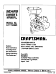
CRAFTSMAN
CARBURETOR
4-CYCLE
ENGINE MODEL: 143.804082
NO, 632208
Ref
P_t
No.
No.
REWIND
STARTER
P_tName
i
2
3
4
5
6
7
8
9
10
11
12
13
14
15
16
17
18
19
2O
6322O8
631615
631767
631036
6.5O5O6
630766
650417
31841
630735
63O758
6315621
630738
630739
"630740
630737
"630748 I
632164
*630746
631049
630742
*630332
21
22
23
24
25
26
27
28
29
630750
%30978
630751
650545
632042
631184
631971
631183
631893
Carburetor
Shaft _t Lever Assyo, Throttle
Spring, Throttle return
Shutter, Throttle
Screw, Throttle 8 Choke shutter
Sprlng, Idle regulating screw
Screw, idle regulating
Shaft 8 Lever Assyo, Choke
Spring, Choke positioning
Shutter, Choke
Screw, Idle adjustment
Spring, Adjustment
screw
Washer, Adjustment
screw
"0" Ring, Adjustment
screw
Screw, Main adjustment
Plug, Welch
Fitting, Fuel
Plug, Welch
Spring, Needle valve
Gasket, Needle valve seat
inlet Needte, Seat, Gasket _f Spring
Assy. (Incl NOSo 18 _ 19)
Gasket, Diaphragm
Diaphragm
Assy., (lneL Noo 21)
Cover, Diaphragm
Screw, Pan flex hd., 6-32 x 3/8
Spring, Choke return
Washer,
Fiat
Seat, Dust
Washer, Felt
Repair Kit (includes items
marked *)
NO. 590642
i
Ref.
No,
i Part
Part
NO.
1590642
t
2
3
4
5
6
7
8
9
10
ti
12
9
7-----f
_s
_ _--4
13
Q_2
23
Name
Starter, Rewind
Pin, Spring (Incl. No, 4)
Washer
Retainer
Washer
Spring, Brake
Dog, Starter
Spring, Dog
Pulley
Spring, Rewind
Cover, Spring
Housing Assy., Starter
Rope, Starter (Length 62" 8" 9/64"
dia.)
Handle, Starter
590599A
59o6oo
59o615
.5906O1
59o598
5._616
5906_7
i 590618
590619
159o535
OWNER'S
MANUAL
MODEL NO.
536.797510
9 INCH-.
2.5 HORSEPOWER
EDGER
Each EDGER
has its own MODEL
NUMBER
on
a model plate on the frame behind the engine
Each ENGINE has its own MODEL
found on the BLOWER HOUSING,
NUMBER
Always mention these MODEL NUMBERS when
requesting
service or Repair Parts for your
EDGER°
All parts listed herein may be ordered through
any Sears Service Center/Departments
and most
Sears Stores.,
WHEN ORDERING
GIVE THE FOLLOWING
REPAIR
PARTS, ALWAYS
INFORMATION:
* PRODUCT - "EDGER"
HOW TO ORDER
REPAIR PARTS
* MODEL NUMBER - 536°797510
* ENGINE MODEL NUMBER - 143.804082
* PART NUMBER
* PART DESCRIPTION
"Your Sears merchandise has added value when you
consider that Sears has service units nationwide staffed
with Sears trained technicians_oProfessional technicians
specifically trained on Sears Products, having the parts,
tools and equipment to insure that we meet our pledge
to you. ,.we service what we sell."
SEARS, ROEBUCK AND CO., Chicago IL 60684
308408 01t22190
Printed
in U.S°A.