1
16X16 DVI Matrix Switch
User’s Guide
Model
SW-DVI-16X16
© 2008 Avenview Inc. All rights reserved.
The contents of this document are provided in connection with Avenview Inc. (“Avenview”) products. Avenview makes no representations
or warranties with respect to the accuracy or completeness of the contents of this publication and reserves the right to make changes to
specifications and product descriptions at any time without notice. No license, whether express, implied, or otherwise, to any intellectual
property rights is granted by this publication. Except as set forth in Avenview Standard Terms and Conditions of Sale, Avenview assumes
no liability whatsoever, and disclaims any express or implied warranty, relating to its products including, but not limited to, the implied
warranty of merchantability, fitness for a particular purpose, or infringement of any intellectual property right.
Reproduction of this manual, or parts thereof, in any form, without the express written permission of Avenview Inc. is strictly
prohibited.
www.avenview.com
1
Table of Contents
Section 1: Getting Started ...................................................................................................................... 4
1.1
Important Safeguards ............................................................................................................ 4
1.2
Safety Instructions ................................................................................................................. 4
1.3
Regulatory Notices Federal Communications Commission (FCC) ......................................... 4
1.4
Introduction ........................................................................................................................... 5
1.5
Package Contents................................................................................................................... 5
1.6
Before Installation.................................................................................................................. 5
Section 2: Installation ............................................................................................................................. 6
2.1
I/O Connections ..................................................................................................................... 6
2.2
Device Operation ................................................................................................................... 6
2.1.1
Front Panel ..................................................................................................................... 6
2.1.2
Device Power On ............................................................................................................ 6
2.1.3
Lock or Unlock the Panel ................................................................................................ 7
2.1.4
Switch Input Channel to Output Channel ...................................................................... 7
2.1.5
Macro Operation ............................................................................................................ 8
2.1.6
Test Signal Board .......................................................................................................... 10
2.1.7
Other Functions ............................................................................................................ 11
Section 3: System Management .......................................................................................................... 12
3.1
Description ........................................................................................................................... 12
3.1.1
Control by RS232 .......................................................................................................... 12
3.1.2
Control by Network ...................................................................................................... 12
3.1.3
Control the Device by NET Control Command ............................................................. 14
3.1.4
Control the Device by WEB Interface ........................................................................... 14
3.1.5
Communication Format A ............................................................................................ 14
3.1.6
Commands ................................................................................................................... 15
3.1.7
Communication Format B ............................................................................................ 22
Section 4: Maintenance ....................................................................................................................... 27
4.1
Replace the Fuse .................................................................................................................. 27
4.2
General Troubleshooting ..................................................................................................... 27
Section 5: Specifications....................................................................................................................... 28
www.avenview.com
2
www.avenview.com
3
Section 1: Getting Started
1.1
Important Safeguards
Please read all of these instructions carefully before you use the device. Save this manual for future
reference.
What the warranty does not cover
Any product, on which the serial number has been defaced, modified or removed.
Damage, deterioration or malfunction resulting from:
Accident, misuse, neglect, fire, water, lightning, or other acts of nature, unauthorized
product modification, or failure to follow instructions supplied with the product.
Repair or attempted repair by anyone not authorized by us.
Any damage of the product due to shipment.
Removal or installation of the product.
Causes external to the product, such as electric power fluctuation or failure.
Use of supplies or parts not meeting our specifications.
Normal wear and tear.
Any other causes which does not relate to a product defect.
Removal, installation, and set-up service charges.
1.2
Safety Instructions
Do not dismantle the housing or modify the module.
Dismantling the housing or modifying the module may result in electrical shock or burn.
Refer all servicing to qualified service personnel.
Do not attempt to service this product yourself as opening or removing housing may expose you to
dangerous voltage or other hazards
Keep the module away from liquids.
Spillage into the housing may result in fire, electrical shock, or equipment damage. If an object or liquid
falls or spills on to the housing, unplug the module immediately.
Have the module checked by a qualified service engineer before using it again.
1.3
Regulatory Notices Federal Communications Commission (FCC)
This equipment has been tested and found to comply with Part 15 of the FCC rules. These limits are designed
to provide reasonable protection against harmful interference in a residential installation.
Any changes or modifications made to this equipment may void the user’s authority to operate this
equipment.
www.avenview.com
4
1.4
Introduction
Avenview SW-DVI-16X16 Matrix Switch is specially designed for switching 16 DVI input signals to 16 DVI
outputs. It is ideal for applications that need DVI operation, such as big screen TV, TV education, TV and
Telephone conference, multimedia meeting room etc.
-
1.5
Supports 16 DVI-D input channel and 16 DVI-D output channels
The EDID of the monitor can be preset
EDID information is saved in the memory for sudden power failure
Input signal monitor and indication
Output load monitor and indication
Supports both RS232 and TCP/IP control
Web based interface for managing the device
LED status to indicate the source and output displayed
Supports up to 1600x1200 resolution
Embedded circuit in device to generate signals for testing and debugging systems
Package Contents
Before you start the installation of the converter, please check the package contents.
-
SW-DVI-16X16
Power Supply
x1
x1
-
User’s Manual
x1
1.6
Before Installation
Put the product in an even and stable location. If the product falls down or drops, it may cause an
injury or malfunction.
Don’t place the product in too high temperature (over 50°C), too low temperature (under 0°C) or high
humidity.
Use the DC power adapter with correct specifications. If inappropriate power supply is used then it
may cause a fire.
Do not twist or pull by force ends of the optical cable. It can cause malfunction.
www.avenview.com
5
Section 2: Installation
Follow these instructions for installation of SW-DVI-16X16:
1.
2.
3.
4.
Mount or fix the SW-DVI-16X15 safely
Connect the SW-DVI-16X16 to included external power supply (50Hz 200V) through the power cable
If controlling the SW-DVI-16X16 through RS232 port then connect the included RS232 serial cable
Connect RJ45 cable to SW-DVI-16X16
This equipment should be used in a main power system with a grounded (neutral)
conductor. The third (grounding) pin is a safety feature, do not attempt to bypass or
disable it.
2.1
I/O Connections
Connect the DVI output of the source DVI signal to IN1 ~ IN16 of the SW-DVI-16X16 Matrix Switch. Connect
the DVI cable to output connector of the SW-DVI-16-16.
For safety consideration, please cut off the power supply before replacing signal cable.
2.2
Device Operation
2.1.1
Front Panel
2.1.2
Device Power On
SW-DVI-16X16 has a self check with a bell warning when the unit powers on. No command will respond during
10 seconds of initial power on.
www.avenview.com
6
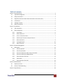
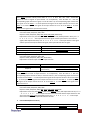
2.1.3
Lock or Unlock the Panel
If the panel is locked, press the LOCK button will unlock the panel or if panel is locked then press the LOCK
button to unlock it. The LED display will show lock or unlock status as shown in the figure below.
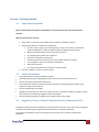
2.1.4
Switch Input Channel to Output Channel
If the panel is locked, the device will have a bell warning when I/O button is pressed. Or if the panel is
unlocked, the LED displays the I/O menu as shown in the figure below.
①:The present switch operation is only to Video
②:Output channel number
③:Input channel number
Example 1: To Switch Input Channel 2 to Output Channel 15
1.
2.
Unlock the Panel as described above
Select Operation Format: Troll the ENTER button to move the cursor to 1 and press the I/O or ENTER
button. The format symbol will blink. Troll the ENTER button to select the format symbol from “A”,
“V”, and “A/V” and press the I/O or ENTER button to set the format symbol.
Format Symbol A = Operation is Audio Only
Format Symbol V = Operation is Video Only
Format Symbol A/V = Operation is Audio / Video (This device only has “V” operation format)
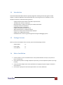
3.
Select Output Channel: Troll the ENTER button to move the cursor to ②, and press the I/O or ENTER
button, then the output channel symbol “16” blinks. Troll the ENTER button to set the output channel
to be “15”, and press the I/O or ENTER button to confirmed the output channel, then the LED displays
as shown in the figure below
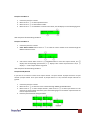
4.
Select Input Channel: Troll the ENTER button to move the cursor to ③and select the input channel in
the same way as selecting the output channel. Press the I/O or ENTER button and then finish to
switch Input channel 2 to output channel 15,and the LED displays as shown in the figure below.
www.avenview.com
7
LOCK the panel when finished setting the channel.
Example 2: Turn OFF Output Channel 15
1.
2.
3.
4.
Unlock the panel if the panel locked
Select operation format
Select output channel
Set input channel to be “OFF” in the same way as selecting input channel. Then finish to off
output channel 15,and the LED displays as shown in figure below.
LOCK the panel when finished setting the channel.
2.1.5
Macro Operation
If the panel locked, the device will have a bell warning when press the MACRO button, or if the panel
unlocked, the LED will display the MACRO menu as the following figure 7 when press the MACRO button.
The panel can save only ten macros, and the macros content can only be set through the
panel, namely through RS232 communication you can not change the content of the ten
macros.
Macro menu has 3 sub-menus:
1.
2.
3.
Load Macro: Load the macro content to the device
View Macro: View the macro content
Modify Macro: Set the macro content
www.avenview.com
8
Example: Load Macro 3
1.
2.
3.
4.
Unlock the panel if it is locked
Move cursor to ① to select operation format
Move cursor to ② to select Macro number.
Move cursor to ③ to load Macro 3 content to the device, the LED display is as the following figure 9.
LOCK the panel if finished setting the Macro
Example: Load Macro 3
1.
2.
Unlock the panel if it is locked
Select Macro Number: Move cursor to ① to select the macro number to be viewed through the
MACRO and Enter button.
3.
View macro content: Move cursor to ②,troll ENTER button to view each output channel, and ③
displays the corresponding input channel, if ③ displays “OFF” means output channel is off, if ③
displays “--” means output channel is ignored.
LOCK the panel if finished setting the Macro
Example: Modify Macro 8
If you want to set macro 8 content to be output channel 2 to input channel 12,output channel 5 to input
channel 5,output channel 10 to input channel 10, output channel 7 is off, and other output channels are
ignored.
1.
2.
3.
4.
Unlock the panel if it is locked
Move cursor to ① to select the macro number 8 through MACRO and ENTER button.
Move cursor to ② to select output channel 2, Move cursor to ③ to select input channel 12. The
same way to set the output channels 5,7,10 as the following figure 12. And other output channels set
to be as output channel 16.
LOCK the panel if finished setting the Macro
www.avenview.com
9
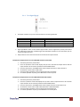
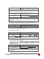
2.1.6
1.
Test Signal Board
The output resolution is up to the two bits of DIPs on the test signal board.
DIPS
OFF
OFF
ON
ON
BIT 1
OFF
ON
OFF
ON
BIT2
Output Resolution: 1600x1200x60Hz
Output Resolution: 1280x1024x60Hz
Output Resolution: 1280x960x60Hz
Output Resolution: 1152x864x75Hz
2.
Signal type Button: There are four kinds of signal saved in the test signal board, namely color vertical
bar, white-black vertical bar, chessboard-grid and white-black vertical line. Press the button you can
choose the signal you need.
3.
Output channel 17 has the same function as the former 16 output channels.
Example: Set Output Channel 17 to be 1600x1200 and Color Vertical Bar
1.
2.
3.
4.
5.
6.
Unlock the panel if the panel locked.
Press the I/O button and the LED displays the I/O menu. Set both the output channel and the
input channel to be 17 with the I/O button and the ENTER button.
Press the I/O button or the ENTER button will tie output channel T1 to input channel T1.
Set the DIPs to be Bit 1 OFF and Bit 2 OFF.
Press the Signal type Button to set the signal to be color vertical bar.
IF no other operation on panel, press LOCK button to lock the panel.
Example: Set Output Channel 17 to be 1280x1024 and Chessboard Grid
1.
2.
3.
4.
5.
6.
Unlock the panel if the panel locked.
Press the I/O button and the LED displays the I/O menu. Set the output channel to be 3 and the
input channel to be T1 with the I/O button and the ENTER button.
Press the I/O button or the ENTER button will tie output channel 3 to input channel T1.
Set the DIPs to be Bit 1 OFF and Bit 2 OFF (Resolution: 1280×1024×60Hz).
Press the Signal type Button to set the signal to be chessboard-grid.
IF no other operations on panel, press LOCK button to lock the panel.
www.avenview.com
10
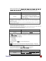
2.1.7
Other Functions
If the panel locked, the device will have a bell warning when press the MENU button, or if the panel
unlocked, the LED will display the MENU menu as the following figure 14 when press the MENU button.
① Check device information about input signal and output load.
② Check device information about temperature and voltage.
③ Set cable length of input channel.
④ Copy output channel EDID to input channel.
Example: Check Device Input Channel Signal
To the following submenu, the cursor is at ①.
① Input channel number
② Signal symbol: if ② displays “1”, the corresponding input channel has active signal, or no signal.
You can view each input channel signal symbol through trolling ENTER button
Example: Copy Output Channel 10 EDID to Input Channel 8
To the following submenu, the cursor is at ①.
1.
2.
3.
4.
Unlock the panel if the panel locked (The LED displays as above figure).
Select input channel number: Select input channel 8 through MENU and ENTER button.
Select output channel number: Move cursor to ②, select output channel 10 and press the
MENU or ENTER button then finish to Copy Output Channel 10 EDID to Input Channel 8.
IF no other operation on panel, press LOCK button to lock the panel.
www.avenview.com
11
Section 3: System Management
3.1
Description
SW-DVI-16X16 can be managed by two different ways: RS232 or through Network (IP)
3.1.1
1.
2.
Control by RS232
Male 9-Pin D Connector:
Pin 2: RXD
Pin 3: TXD (Send)
(Receive)
Pin 5: GND
Other Pins: N/A
(Ground)
Baud Rate: 9600 bit/s, 8 bit, one stop bit, no parity bit
3. Protocol Format: SW-DVI-16X16 supports both the LIGUO hex protocol format (the A communication
format) and the B communication format.
4. Command:
Format of sending: 0xEB,Address,Command,Length of data,Data1,...,Data n,Redundancy.
0xEB
Address:
Frame starting point, binary system showing:11101011.
Code of the device, set before stepping off the product line, unchangeable,
all the devices of the same series have the same address.
Command:
Data length:
Show the commands by hexadecimal data.
The number of the bytes received or sent, only including those of from Data
1 to Data 4
Check whether it is right in the process of sending or receiving. It is
counted by the sending part when sending data and by the device when
send back the data. Method:
Redundancy= Address + Command + Data length + Data 1+…+Data n
If Redundancy=EBH, then Redundancy=14H;
If Redundancy has carry, ignore the carry and get Low 8 bits.
For example, EBH, 90H, 01H, 01H, F3H, 90H
Redundancy = 90H + 01H + 01H + F3H = 185H
Ignore the carry, e.g. Redundancy=85H.
Redundancy:
3.1.2
1.
2.
Control by Network
Protocol: SW-DVI-16X16 supports the network control based on TCP/IP protocol, RJ-45 port offers
physical connect between the equipment and net. Actually, the equipment has a default IP address
that is 192.168.0.104 and the MAC address is labeled at the back of equipment. There are two
indicator lights reflect the net connecting state. The closer light shows the power is on or not. The
steady shining indicator light shows power on. The blinking light shows the net is working, the going
out light means the power does not connect. Another indicator light shining means connection of the
net port is common; otherwise the light going out is abnormal.
Set a new parameter of the IP address according to the existing one:
a.
Make sure the net ready to work and the device connected to net;
www.avenview.com
12
b.
c.
d.
e.
According to the DOS direction, input the command: telnet 192.168.0.104 9999
(192.168.0.104 9999 is the current device’s IP address) then the information shows as
follows. The serial code of produce: XXXXXXX
MAC address: XX:XX:XX:XX:XX:XX
Vision number of Software: XX.X (XXXXXX)
Press “Enter” to come into the mode of setting parameter.
Press “Enter” button on keyboard to show the info as below
Change setting: 0 server setting;
1 serial interface setting;
6 safety setting;
7 resume default setting;
8 quit without save;
9 quit and save
Choose step: ??
Press 0 and then “Enter”. Information as follows: IP address: <192>
Input IP address and then “Enter”. Information as follows:
IP address of setting net gateway: <N>
f.
g.
h.
i.
j.
k.
Press “Enter” and then showing as follows:
The masking of subnet: digit of the inputted masking<0=default>
Press “enter” and then showing as follows:
Change the passport of telnet (N)
Press “enter” then showing as follows:
Change set:
0 server setting;
1 serial interface setting;
6 safety setting;
7 resume default setting;
8 quit without save;
9 quit and save
Choose step: ?
Input 9 and press “Enter” to save and quit the operation.
Input the command: ping 192.168.0.104, if the above operation is successful, information is
showed as follows:
Pinging 192.168.0.104 with 32 bytes of data:
Reply from 192.168.0.104: bytes=32 time<10ms TTL=64
Reply from 192.168.0.104: bytes=32 time<10ms TTL=64
Reply from 192.168.0.104: bytes=32 time<10ms TTL=64
Reply from 192.168.0.104: bytes=32 time<10ms TTL=64
Ping statistics for 192.168.0.104:
Packets: Sent = 4, Received = 4, Lost = 0 (0% loss), Approximate round trip times in
milli-seconds: Minimum = 0ms, Maximum = 0ms, Average = 0ms
3.
Set a new parameter of IP address according to device’s MAC address:
a.
Record the Mac address at rear keyboard.
www.avenview.com
13
b.
c.
d.
According to DOS direction, Input the command: arp -s 192.168.0.123 XX-XX-XX-XX-XX-XX
(192.168.0.123 is temporary address; XX-XX-XX-XX-XX-XX is the MAC address of equipment)
and press, “enter”.
Input “telnet 192.168.0.123 1”
Input “telnet 192.168.0.123 9999”. After that set up and save a new IP address based on
your existing IP schema
Since the IP address assigned is temporary, if unit is restarted without saving the IP
address, it will be lost. To save IP address input command “telnet 192.168.0.123
9999” to save the new IP address.
3.1.3
Control the Device by NET Control Command
If you need to control the SW-DVI-16X16 Matrix Switch via Internet, then the unit must connect to Internet,
and SW-DVI-16X16 must be host computer, controlling equipment must be assistant computer. Before using
command, controlling equipment need send connection request to SW-DVI-16X16 via TCP/IP protocol, and
then build a net. After that send the commands to host computer, data are all binary system, communication
command and protocol formats same as RS232 controlling format, the supporting commands are same as
RS232’s commands.
3.1.4
1.
Control the Device by WEB Interface
Introduction of WEB control mode
SW-DVI-16X16 has a WEB server inside, this server supplies supervision function about working state
data, such as device’s inside temperature and power voltage, and control device’s input and output
via web. After set up a correct net control parameter (IP address), the device can be available through
HTTP.
2.
3.
4.
Control process
For example: control process is based on TCP/IP, OS is “Widows” professional, IE 6.0, JRE1.4.6 (JAVA
Run Time Environment) inside.
Make sure the device connects to Internet via “ping” command.
Start up browser; input IP address, like http://192.168.0.104 and then the web will display that is
inside the host computer.
3.1.5
1.
2.
3.
4.
Communication Format A
Format of Character All data are showed by hexadecimal data.
Explanation of character
The symbol“,” and “.” just stands for list separator without any meanings, and wouldn’t be sent in the
process of sending data. The data with “under line” or “black type” are key words.
Data length
The data must be among 0x01~0xFF excluding 0xEB, represent the quality of data 1~ data n and are
accordant with the subsequent data.
0x00
It stands for any number from 0x00 to 0xFF excluding 0xEB.
www.avenview.com
14
5.
6.
7.
8.
9.
Output data 1~N
It symbolized codes of output ports; the range is from 0x00 to the maximum number that the device
supports.
Input data 1~N
It symbolized codes of input ports; the range is from 0x00 to the maximum input number that the
device supports. 00x0 means input No.1; 0x01 means input No.2. Please caution that the maximum
input port number’s code plus ONE symbolized closing this port. For example, the device supports
eight input ports, then 0x07 symbolizes No.8 port, 0x08 symbolizes close.
Pre-select input through long-distance control
Similar with input by keyboard
Address
0x90
Response
a. The equipment correctly receives and executes the command. Then execute the command and
response as follows. 0xeb,Address,Command,0x01,0xfa,Redundancy.
b. The equipment receives the address correctly but data out of the range. Then doesn’t execute
the command and response as follows. 0xeb , Address , Command , 0x01 , 0xf2 ,
Redundancy.
c. The equipment receives correctly but is controlled through keyboard. Then doesn’t execute the
command and response as follows. 0xeb,Address,Command,0x01,0xf3,Redundancy.
d. The equipment receives the address correctly but data length wrongly. Then doesn’t execute
the command and response as follows. 0xeb , Address , Command , 0x01 , 0xf7 ,
Redundancy.
e. The equipment receives the address correctly but the command is no support. Then doesn’t
execute the command and response as follows. 0xeb,Address,Command,0x01,0xf1,
Redundancy.
f. The equipment receives the address wrongly. No response.
3.1.6
1.
Commands
Command 0x00(two functions)
Function 1
Format
Response
Get the equipment address and software version
0xeb, 0x00, 0x00, 0x01, 0x01
0xeb, Address, 0x00, 0x02, Version, 0xfa, Redundancy
For example:Get the equipment address and software version
Commands: 0xeb, 0x00, 0x00, 0x01, 0x01
Response: 0xeb, 0x90, 0x00, 0x02, 0x10, 0xfa, Redundancy
Function 2
Format
Response
Get the information of the equipment’s type
0xeb, 0x90, 0x00, 0x01, 0x49
0xeb, 0x90, 0x00, 0x03, Input Signal Type,Maximal Input
Channel Quantity,Maximal Output Channel Quantity
Note: The value of Input Signal Type is 0x80,it means DVI type
www.avenview.com
15
For example:Get the information of equipment’s type
Commands: 0xeb, 0x90, 0x00, 0x01, 0x49
Response: 0xeb, 0x90, 0x00, 0x03, 0x80, 0x10, 0x10, Redundancy
2.
Command 0x01
Function
Tie the input channel to output channel
0xeb, 0x90, 0x01, N, Input Number of output channel
Format
1…Input Number of output channel N.
Response
0xeb, 0x90, 0x01, 0x01, 0xfa, Redundancy
Note: The range of N is from 0x01 to 0x11.
Note: The range of Input Number is from 0x00 to 0x11. 0 means INPUT 1, 1 means INPUT 2, 0x11
means closing output.
For example 10:Tie the input channel 8 to the output channel 1, the input channel 17 to the output
channel 2 and close the output channel 3.
Commands: 0xeb, 0x90, 0x01, 0x03, 0x07, 0x10, 0x11
Response: 0xeb, 0x90, 0x01, 0x01, 0xfa, Redundancy
3.
Command 0x02
Tie the appointed output channels to the appointed input
channels.
Function
0xeb , 0x90, 0x02, N, Output Number 1,Input Number
1,…,Output Number N, Input Number N
Response
0xeb, 0x90, 0x02, 0x01, 0xfa, Redundancy
Note: The range of N is the even from 0x02 t0 0x22.
Note: The range of Output Number is from 0x00 to 0x10. 0x10 stands for the test output.Note 3: The
range of Input Number is from 0x00 to 0x11. 0x11 is used to close the output. 0x10 is used to tie the
output to the internal test signal.
Format
For example 1: Tie the input channel from 1 to 8 to output channel from 1 to 8 respectively.
Commands: 0xeb, 0x90, 0x02, 0x10, 0x00, 0x00, 0x01, 0x01, 0x02, 0x02, 0x03, 0x03, 0x04, 0x04, 0x05,
0x05, 0x06, 0x06, 0x07, 0x07
Response: 0xeb, 0x90, 0x02, 0x01, 0xfa, Redundancy
For example 2: Tie the input channel 2 to the output channel 8
Commands: 0xeb, 0x90, 0x02, 0x02, 0x07, 0x01
Response: 0xeb, 0x90, 0x02, 0x01, 0xfa, Redundancy
4.
Command 0x03(three functions)
Function 1
Format
Response
Get the marks of signals at input channels
0xeb, 0x90, 0x03, 0x01, 0x00
0xeb, 0x90, 0x03, 0x04, Mark 1, Mark 2, Mark 3, Mark
4,Redundancy
www.avenview.com
16
Note: Mark 1 expresses in binary as this mode “ 0,0,0,0,bit3,bit2,bit1,bit0 ”,bit0 to bit3
means the marks of signals at input channel 1 to 4 respectively,if the bit value is 1,then the
corresponding input channel has signal, or if the bit value is 0, the corresponding input channel has
not signal. So to the Mark 2,its value expresses the signals of the input channel 5 to 8. So to the
Mark 3,its value expresses the signals of the input channel 9 to 12. So to the Mark 4,its value
expresses the signals of the input channel 13 to 16.
For example 1: Get the marks of signals at input channels
Commands: 0xeb, 0x90, 0x03, 0x01, 0x00
Response: 0xeb, 0x90, 0x03, 0x04, 0x08, 0x04, 0x00, 0x00, Redundancy
Explanation: At this time, the Mark 1 is 08H and the Mark 2 is 04, 0x08 expressed in binary is“0,0,
0,0,1,0,0,0 ”, so the input channel 4 has signal and the input channel 1 to 3 have not
signals; 0x04 expressed in binary is“0,0,0,0,0,1,0,0”,so the input channel 7 has signal
and the input channel 5,6 and 8 have not signal, other input channels have no signal.
Function 2
Get the Preset Input Channel
Format
0xeb, 0x90, 0x03, 0x01, 0x01
Response
0xeb, 0x90, 0x03, 0x01, Preset Input Channel,Redundancy
Note: The range of the Preset Input Channel is as same as the Maximal Input Channel
For example: Get the Preset Input Channel
Commands: 0xeb, 0x90, 0x03, 0x01, 0x01
Response: 0xeb, 0x90, 0x03, 0x01, 0x04, Redundancy
Explanation: The Preset Input Channel is input channel 5.
Function 3
Format
Get the mark of the load at the output channels
0xeb, 0x90, 0x03, 0x01, 0x04
0xeb, 0x90, 0x03, 0x05, Mark 1, Mark 2, Mark 3, Mark 4, Mark
Response
5,Redundancy
Note: Mark 1 expresses in binary as this mode “ 0,0,0,0,bit3,bit2,bit1,bit0 ”,bit0 to bit3
means the marks of Load at output channel 1 to 4 respectively,if the bit value is 1,then the
corresponding output channel has load, or if the bit value is 0, the corresponding output channel has
not load. So to the Mark 2,its value expresses the signals of the output channel 5 to 8. So to the Mark
3,its value expresses the signals of the output channel 9 to 12. So to the Mark 4,its value expresses
the signals of the output channel 13 to 16. So to the Mark 5,its value expresses the signal of the
output channel 17.
For example: Get the mark of the load at the output channel
Commands: 0xeb, 0x90, 0x03, 0x01, 0x04
Response: 0xeb, 0x90, 0x03, 0x05, 0x05, 0x01, 0x00, 0x00, 0x00, 0x9b
Explanation: At this time, the Mark 1 is 0x05 and the Mark 2 is 0x01, 0x05 expressed in binary is“0,0
,0,0,0,1,0,1 ”, so the output channels 1 and 3 have loads and the output channels 2 and
4 have not loads; Mark 2 0x01 expressed in binary is“0,0,0,0,0,0,0,1”,so the output
channel 5 has load. Other output channels have no loads.
5.
Command 0x04(three functions)
Function 1
Format
Get the tied status of an appointed input channel
0xeb, 0x90, 0x04, 0x02, 0x01, Input Number
www.avenview.com
17
0xeb, 0x90, 0x04, N, Output Number 1 , … , Output
Number N,Redundancy
Note: The range of Input Number is as same as the note 2 of command 0x01
Note: The range of Output Number is as same as the note 2 of command 0x02
For example:Get the tied status of an appointed input channel
Commands: 0xeb, 0x90, 0x04, 0x02, 0x01, 0x04
Response: 0xeb, 0x90, 0x04, 0x02, 0x01, 0x05, Redundancy
Explanation: The input channel 5 has been tied to output channels 2 and 6.
Response
Function 2
Get the tied status of an appointed output channel
Format
0xeb, 0x90, 0x04, 0x02, 0x02, Output Number
Response
0xeb, 0x90, 0x04, 0x01, Input Number, Redundancy
Note: The range of Output Number is as same as the note 2 of command 0x02.
Note: The range of Input Number is as same as the note 2 of command 0x01.
For example: Get the tied status of an appointed output channel
Commands: 0xeb, 0x90, 0x04, 0x02, 0x02, 0x04
Response: 0xeb, 0x90, 0x04, 0x01, 0x07, Redundancy
Explanation: The output channel 5 has been tied to input channel 8.
Function 3
Format
Get the tied status of all output channels
0xeb, 0x90, 0x04, 0x01, any data except 0xeb
0xeb, 0x90, 0x04, 0x08, Input Number of output channel1,
Response
…, Input Number of output channel 16, Redundancy
Note: The range of Input Number is as same as the Note 2 of command 0x01
For example: Get the tied status of all output channels
Commands: 0xeb, 0x90, 0x04, 0x01, 0x01
Response: 0xeb, 0x90, 0x04, 0x11, 0x00, 0x01, 0x02, 0x03, 0x04, 0x05, 0x06, 0x07, 0x08, 0x09, 0x0a,
0x0b, 0x0c, 0x0d, 0x0e, 0x0f, 0x10, Redundancy
Explanation: The output channel from 1 to 17 has been tied to input channel from 1 to 17
respectively.
6.
Command 0x05
Function
Set the Preset Input Channel
Format
0xeb, 0x90, 0x05, 0x01, Input Number
Response
0xeb, 0x90, 0x05, 0x01, 0xfa, Redundancy
Note: The range of Input Number is as same as the Note 2 of command 0x01
For example:Set the Preset Input Channel
Commands: 0xeb, 0x90, 0x05, 0x01, 0x02
Response: 0xeb, 0x90, 0x05, 0x01, 0xfa, Redundancy
Explanation: The Preset Input Channel is set up to input channel 3.
7.
Command 0x06
Function
Format
Response
Tie an appointed output channel to the Preset Input
Channel.
0xeb, 0x90, 0x06, 0x01, Output Number
0xeb, 0x90, 0x06, 0x01, 0xfa, Redundancy
www.avenview.com
18
Note: The range of Output Number is as same as the Note 2 of command 0x02
For example: Tie an appointed output channel to the Preset Input Channel
Commands: 0xeb, 0x90, 0x06, 0x01, 0x04
Response: 0xeb, 0x90, 0x06, 0x01, 0xfa, Redundancy
Explanation: The output channel 5 has been tied to the Preset Input Channel.
8.
Command 0x0c
Function 1
Recode Macro
0xeb, 0x90, 0x0c, N, 0x00, Macro Number, Output Number 0
,Input Number 0,…,Output Number N,Input Number
Format
N, Redundancy
Response
0xeb, 0x90, 0x0c, 0x01, 0xfa, 0x0f
Note: The range of N is the even from 0x02 to 0x22
For example:Recode the Macro 1
Commands: 0xeb, 0x90, 0x0c, 0x06, 0x00, 0x00, 0x01, 0x01, 0x02, 0x02,
Response: 0xeb, 0x90, 0x0c, 0x01, 0xfa, Redundancy
Explanation: In this Macro, the Macro number is 1, the output channel 2 、3 is tied to the input
channel 2、3 respectively and other output channels are ignored
Function 2
View Macro
Format
0xeb, 0x90, 0x0c, 0x02, 0x02, Macro Number
0xeb, 0x90, 0x0c, N, Macro Number,Output Number 0,
Response
Input Number 0,…,Output Number M,Input Number M
, Redundancy
Note: The range of Macro Number from 0x00 to 0x10
Note: The range of N is an odd from 0x01 to 0x21
For example: View Macro Number 1
Commands: 0xeb, 0x90, 0x0c, 0x02, 0x02, 0x00
Response: 0xeb, 0x90, 0x0c, 0x05, 0x00, 0x01, 0x01, 0x02, 0x02, Redundancy
Explanation: In the Macro number 1: the output channel 2 、3 is tied to the input channel 2、3
respectively and other output channels are ignored.
Function 3
Recall Macro.
Format
0xeb, 0x90, 0x0c, 0x02, 0x01, Macro Number
Response
0xeb, 0x90, 0x0c, 0x01, 0xfa, 0x0f
Note: The range of Macro Number is from 0x00 to 0x10.
For example: Recall Macro Number 1
Commands: 0xeb, 0x90, 0x0c, 0x02, 0x01, 0x00
Response: 0xeb, 0x90, 0x0c, 0x01, 0xfa, Redundancy
9.
Command 0xfd (three functions)
Function 1
Format
Response
View the status of switching EDID
0xeb, 0x90, 0xfd, 0x02, 0x02, 0x00
0xeb, 0x90, 0xfd, 0x10, the EDID mark of the input
www.avenview.com
19
channel 1,……,the EDID mark of the input channel 16,
Redundancy
Note: 0x10 is the num of input channels. If the EDID mark of the input channel 1 is 0x01, it means
the EDID of the output channel 2 is copied to the input channel 1, and so to the mark of other
input channels. If the mark is 0x11, it means the default EDID is copied to the input.
Copy the EDID of Load at the appointed output channels
to the appointed input channels
0xeb, 0x90, 0xfd, N, 0x01, the EDID source of Input
Format
channel 1… the EDID source of Input channel N
Response
0xeb, 0x90, 0xfd, 0x01, 0xfa, Redundancy
Note: The range of N is from 0x01 to 0x10
Note: The range of the EDID source is from 0x00 to 0x0f, they stand for output channel from 1 to
16 respectively.
Note: If there is no load at the appointed output channel, then the default EDID will be used
For example: Copy the EDID of output channels from 4 to 8 to the input channels from 1 to 5
Commands: 0xeb, 0x90, 0xfd, 0x06, 0x01, 0x03, 0x04, 0x05, 0x06, 0x07
Function 2
Function 3
Copy the default EDID to the appointed input channels
Format
0xeb, 0x90, 0xfd, 0x02, 0x02, Input Number
Response
0xeb, 0x90, 0xfd, 0x01, 0xfa, Redundancy
For example: Copy the default EDID to the input channel 5
Commands: 0xeb, 0x90, 0xfd, 0x02, 0x02, Redundancy
10. Command 0xfa (nine functions)
Function 1
Format
Get the signal marks of all input channels
0xeb, 0x90, 0xfa, 0x02, 0x00, 0x00
0xeb, 0x90, 0xfa, 0x11, Mark 1 , … , Mark 16 ,
Response
Redundancy
Note: The value of Mark 1 to Mark 16 is 0x00 or 0x01; if the mark value is 0x01,then the
corresponding input channel has signal, or if the mark value is 0x00, the corresponding input
channel has not signal.
For example:Get the signal marks of all input channels
Commands: 0xeb, 0x90, 0xfa, 0x02, 0x00, 0x00
Response: 0xeb, 0x90, 0xfa, 0x11, 0x00, 0x00, 0x00, 0x00, 0x01, 0x01, 0x01, 0x01, 0x00, 0x00, 0x00,
0x00, 0x00, 0x00, 0x00, 0x00, Redundancy
Explanation: The input channels from 5 to 8 have signals, and other input channels have no signal.
Function 2
Format
Get the load marks of all output channels
0xeb, 0x90, 0xfa, 0x02, 0x00, 0x01
0xeb, 0x90, 0xfa, 0x11, Mark of output channel1,…,
Response
Mark of output channel 17, Redundancy
Note: The value of marks from 1 to 17 is 0x00 or 0x01; if the mark value is 0x01,then the
corresponding output channel has load, or if the mark value is 0x00, the corresponding output
channel has not load.
For example: Get the load marks of all output channels
Commands: 0xeb, 0x90, 0xfa, 0x02, 0x00, 0x01
www.avenview.com
20
Response: 0xeb, 0x90, 0xfa, 0x11, 0x00, 0x00, 0x00, 0x00, 0x01, 0x01, 0x01, 0x01, 0x00, 0x00, 0x00,
0x00, 0x00, 0x00, 0x00, 0x00, 0x00, Redundancy
Explanation: The output channels 5 to 8 have loads; other output channels have no loads.
Function 3
Format
Get the Temperature Value of all sub boards
0xeb, 0x90, 0xfa, 0x02, 0x00, 0x02
0xeb, 0x90, 0xfa, 0x11, Temperature Value of Control
Board , Temperature Value of Input Board 1 , … ,
Temperature Value of Input Board 8,Temperature Value
Response
of Output Board 1,…,Temperature Value of Output
Board 8 ,Redundancy
Note: Actual temperature =(Temperature Value)-20
For example : If the Temperature Value is 0x38, then the actual temperature is
36℃(0x38-20=56-20=36).
Note: if the Temperature Value is zero,then the corresponding sub board or the sub board
temperature sensor is not exit.
For example:Get the information of sub boards temperature
Commands: 0xeb, 0x90, 0xfa, 0x02, 0x00, 0x02
Response: 0xeb, 0x90, 0xfa, 0x11, 0x38, 0x00, 0x00, 0x00, 0x00, 0x00, 0x00, 0x00, 0x00, 0x00, 0x00,
0x00, 0x00, 0x00, 0x00, 0x00, 0x00, Redundancy
Explanation: The temperature of Control Board is 36℃. Other boards are not exit.
Function 4
Format
Get the Voltage value of the control boards.
0xeb, 0x90, 0xfa, 0x02, 0x00, 0x03
0xeb, 0x90, 0xfa, 0x05, 0x00, Data 1(Voltage value),…,
Response
Data 4(Voltage value), Redundancy
Note: 0x03means this operation is to check the control board voltage.
Note: Data 1 to Data 4 value stand for the temperature on different parts of the control board.
The corresponding relation is as follows:
Voltage NO. Normal voltage. Voltage step
1 +2.5V 6.51mV
2 +2.5V 5.86mV
3 +5.0V 13.02mV
4 +12.0V 31.25Mv
The actual temperature=(Data n)× 4 × corresponding voltage step.
For example
If Data 0 value is 0x5F, then the actual temperature is 0x5F×4×6.51=2473.8mV,namely 2.47V.
If Data 3 value is 0x61, then the actual temperature is 0x61×4×13.02=5051.8mV,namely 5.05V.
For example: Get the Voltage value of the control boards
Commands: 0xeb, 0x90, 0xfa, 0x02, 0x00, 0x03
Response: 0xeb, 0x90, 0xfa, 0x05, 0x00, 0x5f, 0x6b, 0x61, 0x6c, Redundancy
Explanation: The corresponding voltage is 2.47V、2.5V、5.0V、13.5V
Function 5
Format
Response
Get the working status
0xeb, 0x90, 0xfa, 0x02, 0x00, 0x04
0xeb, 0x90, 0xfa, 0x03, Mark initialization ,Baud Value
of serial port,Type of equipment, Redundancy
Note: The range of mark initialization is from 0x00 to 0x02, If the mark value is 0x00,then the
www.avenview.com
21
equipment has not been initialized; If the mark value is 0x01, then the equipment has been
initialized, but the module is still without power: If the mark value is 0x02, then the equipment
already power on and work well.
Note: The Baud Value of serial port is fixed 0x00, it stands for 9600bit/s,8bit,1 stop bit, no
parity.
Note: The type of equipment value is 0x80, and it stands for DVI type.
For example: Get the working status
Commands: 0xeb, 0x90, 0xfa, 0x02, 0x00, 0x04
Response: 0xeb, 0x90, 0xfa, 0x03, 0x02, 0x00, 0x80, Redundancy
Explanation: The equipment is in normal working state,the serial communication baud rate is 9600
and the device signal type is DVI .
Function 6
Reset the equipment.
Format
0xeb, 0x90, 0xfa, 0x02, 0xaa, 0x06
Response
0xeb, 0x90, 0xfa, 0x01, 0xfa, 0x85
For example: Reset the equipment.
Commands: 0xeb, 0x90, 0xfa, 0x02, 0xaa, 0x06
Response: 0xeb, 0x90, 0xfa, 0x01, 0xfa, 0x85
Function 7
Set the length of inputs cable.
0xeb, 0x90, 0xfa, 0x04, 0x00, 0x0b, the input channel, the
Format
Value of the length
Response
0xeb, 0x90, 0xfa, 0x01, 0xfa, 0x85
Note: The Value of the length is from 0x00 to 0x0f. If there is no input board, it backs F2.
Function 8
Format
View the length of inputs cable
0xeb, 0x90, 0xfa, 0x02, 0x00, 0x0c
0xeb, 0x90, 0xfa, 0x12, 0x00, 0x0c, the length of the input
channel 1 cable,……, the length of the input channel 16
cable, Redundancy
Response
Function 9
Switch the communication format between A and B
0xeb, 0x90, 0xfa, 0x04, Port num, the num of the format,
0xaa, 0x55
NO
Format
Response
Note: The RS-232 Port is 0x03, and the Network Port is 0x04. The Format Num: 0x00 A, 0x01 B
3.1.7
1.
Communication Format B
Both sent and received data are ASCII characters.
In order to explain conveniently, some special ASCII characters or character strings are expressed
as following: ↵ = CR/LF, “ENTER” First and New line later character. ← = CR,“ENTER”
character only. · = Space,Space character [ESC] = ESC,Code-change character [X] = Character 0
to 9. [X3] = Input channel number(range form 0 to 8,0 means to shut off the channel)
www.avenview.com
22
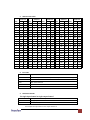
2.
ASCII Character Table
ASCII Val
ASCII Val
ASCII Val
ASCII Val
ASCII Val
Char.
Esc
DEC
27
HEX
1B
Char.
1
DEC
49
HEX
31
Char.
E
DEC
69
HEX
45
Char.
Y
DEC
89
HEX
59
Char.
m
DEC
109
HEX
6D
CR
LF
13
10
0D
0A
2
3
50
51
32
33
F
G
70
71
46
47
Z
[
90
91
5A
5B
n
o
110
111
6E
6F
Space
!
32
33
20
21
4
5
52
53
34
35
H
I
72
73
48
49
\
]
92
93
5C
5D
p
q
112
113
70
71
“
34
22
6
54
36
J
74
4A
^
94
5E
r
114
72
#
$
35
36
23
24
7
8
55
56
37
38
K
L
75
76
4B
4C
_
`
95
96
5F
60
s
t
115
116
73
74
%
&
37
38
25
26
9
:
57
58
39
3A
M
N
77
78
4D
4E
a
b
97
98
61
62
u
v
117
118
75
76
‘
39
27
;
59
3B
O
79
4F
c
99
63
w
119
77
(
)
40
41
28
29
<
=
60
61
3C
3D
P
Q
80
81
50
51
d
e
100
101
64
65
x
y
120
121
78
79
*
+
,
42
43
2A
2B
>
?
62
63
3E
3F
R
S
82
83
52
53
f
g
102
103
66
67
z
{
122
123
7A
7B
-
44
45
2C
2D
@
A
64
65
40
41
T
U
84
85
54
55
h
i
104
105
68
69
|
}
124
125
7C
7D
.
46
2E
B
66
42
V
86
56
j
106
6A
~
126
7E
/
0
47
48
2F
30
C
D
67
68
43
44
W
X
87
88
57
58
k
l
107
108
6B
6C
Del
127
7F
3. Error Code
Error Code
E01↵
Explanation
E05↵
No Communication Allowable
E10↵
Not valid command
E14↵
Not exist command
E22↵
Device is busy
4.
Not valid input channel number (out of the input channel number range)
Detailed Commands
Tie single input channel to single output channel
Function
Format
Response
Tie input channel to output channel
[X3]*[X2] &
OUT[X2]·IN[X3]·DVI↵
For example: Tie input channel 1 to output channel 3
www.avenview.com
23
Commands sent by PC: 1*3&
Response by the device: Out03·In01·DVI↵
Tie multiple input channels to multiple output channels
Function
Format
Response
Tie multiply input channels to multiply output channels
[ESC] Q [X3]*[X2]! … [X3]*[X2]! ←
Out·Multi·In·Multi·All↵
For example: Tie the output channels 4,5,7 to the input channels 3,3,6 respectively
Commands sent by PC: [ESC]Q3*4&3*5&6*7&←
Response by the device: Out·Multi·In·Multi·All↵
Tie all output channels to the appointed input
Function
Format
Response
Tie all output channels to the appointed input
[X3] ! Or [X3]&
Out·Multi·In·[X3]·All↵ or Out·Multi·In·[X3]·DVI↵
For example: Tie all output channels to the appointed input channel 5
Commands sent by PC: 5&
Response by the device: Out·Multi·In·05·DVI↵
Macro command
Function 1
Set Macro
Format
M[X5]·[X3]*[X2]·…*X3+**X2+·E
Response
Sma[X5]↵
For example: Set Macro 6
Macro 6: tie the input channels 16,15,14,13,12,11,10 to the output channels
1,2,3,4,5,6,7 respectively
Commands sent by PC: M6·16*1·15*2·14*3·13*4·12*5·11*6·10*7·E
Response by the device: Sma06↵
Function 2
Load Macro
Format
M[X5]! Or M[X5]&
Response
Rma[X5]·All ↵ or Rma[X5]·DVI↵
For example:Load Macro 2
Commands sent by PC: M2!
Response by the device: Rma02·All↵
Function 3
View Macro
Format
V[X5]; or v[X5];
Response
M[X5]·[X3]*[X2]·…[X3]*[X2]·E
For example:View Macro 5
Commands sent by PC: V5;
Response by the device: M05·01*01·02*02·03*03·04*04·05*05·06*06·E
Response means the output channels 1,2,3,4,5,6 ties to the input channels 1,2,3,4,5,6
respectively.
If the response is M15 E, it means the Macro is not existed.
View the Switch Status of Single Output Channel
www.avenview.com
24
Function
Format
Response
View the status of single output channel
V[X2]& or v[X2]&
Out[X2]·In[X3]·DVI↵
For example: View the switch status of the output channel 7
Commands sent by PC: V7&
Response by the device: Out07·In02·DVI↵
Explanation: The output channel 7 is tied to the input channel 2.
Get the Software Version
Function
Get the software version.
Format
Q or q
Response
Ver[X].[X]↵
Note:”*X+.*X+” stands for software version。
For example :Get the software version.
Commands sent by PC: Q
Response by the device: Ver1.0↵
Explanation: The software version is 1.0.
Get the Voltage Value of the Control Boards
Function
Get the Voltage value of the control boards.
Format
[X4]*2S
Response
Xf·Xf·Xf·Xf·Vol↵
Xf stands for the temperature on different parts of the control board. The corresponding
relation is as follows:
Voltage NO. Normal voltage. Voltage step
1 +2.5V 6.51mV
2 +2.5V 5.86mV
3 +5.0V 13.02mV
4 +12.0V 31.25Mv
The actual temperature=(Data n)× 4 × corresponding voltage step.
For example
If Xf value is 0x5F, then the actual temperature is 0x5F×4×6.51=2473.8mV,namely 2.47V.
For example :Get the Voltage value of the control boards.
Commands sent by PC: 1*2S
Response by the device: 96·82·97·102·Vol↵
Explanation: the actual temperature of respective boards are 2.5V,1.9V,5.05V, 12.75V。
Get the Signal Mark of Input Channels
Function
Get the signal mark of input channels
Format
[X4]*03S
Response
Xf·Xf·…·Xf·Xf·Sig↵
If Xf is 0, it means no signal. If Xf is 1, it means there is signal
For example :Get the signal mark of input channels
Commands sent by PC: 1*3S
Response by the device: 00·00·01·00·00·01·01·00·00·00·00·00·00·00·00·00·Sig↵
Explanation: The input channels 3,6 and 7 have signals.
Get the Load Mark of Output Channels
www.avenview.com
25
Function
Get the load mark of output channels
Format
[X4]*04S
Response
Xf·Xf·…·Xf·Xf·Load↵
If Xf is 0, it means no load. If Xf is 1, it means there is load
For example : Get the load mark of output channels
Commands sent by PC: 1*4S
Response by the device: 00·01·01·01·00·00·00·00·Load↵
Explanation: The output channels 2,3 and 4 have loads.
Get Device Temperature
Function
Get device temperature
Format
[X4]*05S
Response
[X4]Tem[X31]↵
The actual temperature: [X31]-20
For example : Get device temperature
Commands sent by PC: 1*5S
Response by the device: 1Tem51↵
Explanation: The actual temperature is 31.
Get the EDID of Outputs to Inputs
Function
Copy the EDID of the output channel to the input channel
Format
[X1]*[X2]~
Response
[X1]*[X2]·EDID↵
For example :Copy the EDID of the output channel 3 to the input channel 4
Commands sent by PC: 4*3~
Response by the device: 4*3·EDID↵
Copy the Default EDID to Inputs
Function
Copy the default EDID to the input channel
Format
[X1]*15S
Response
Default↵
For example: Copy the default EDID to the input channel 4
Commands sent by PC: 4*15S
Response by the device: Default↵
Reset Command
Function
Reset
Format
[ESC]zXXX
Response
ZapXXX↵
www.avenview.com
26
Section 4: Maintenance
4.1
Replace the Fuse
There is a spare fuse hidden in the power socket. Pull out the power cord and open the place showed on the
picture, then pull out the fuse socket and put in a new fuse.
For safety consideration, please cut off the power supply before replacing the new fusee.
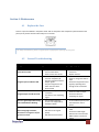
4.2
General Troubleshooting
Problem
Power LED is not ON
Reason
Possible Solution
No Signal Input and IN LED is ON
No Signal Output and IN LED is ON
There is a signal output with wrong
colors and EDID LED is blinking
No power connected
Fuse is melted down
Power cord is short circuit
The cable of Input is short
circuit or completely off
The prior equipment doesn’t
Output signals
The prior equipment is PC
which has never been
disconnected
The cable of output is not
connected
The device is not outputting
signal
The resolution from the
source is not supported by
the Matrix Switch
DVI cable is not of good
quality
DVI cable is over 5 meters
www.avenview.com
Check or change the cable of
Input
Ensure that equipments have
signal by operating them
Change the PC’s resolution
Check the cable of output
Ensure that device is
outputting the signal
Set the supported resolution
on source device (PC etc) and
then restart the source
device
Use high performance DVI
cable
Ensure that cable length
between the source and DVI
Matrix switch is less than 5
meters
When setting high resolution,
either there is no signal or output
signal is not correct
Ensure that power cable is
connected
Replace the fuse
27
Section 5: Specifications
Description
Input Connector
Output Connector
Network Connector
RS232 Connector
Input Resolution
Supported Input Signal
Supported Output Signal
DVI-D x 16
DVI-D x16
RJ45
DB9 Male
1600x1200x60Hz
DVI 1.0
Same as Input Standard
24MHz – 165MHz
RS232 or TCP/IP – 10M
AC 180V ~ 250V 50Hz
100mA
< 40W
Pixel Clock Frequency
Control Options
Power Supply
Max Output Current of Each Channel
Power Consumption
Dimension (mm)
483x133x305 (3U Rack)
6Kg
Weight
www.avenview.com
28
Disclaimer
While every precaution has been taken in the preparation of this document, Avenview Inc. assumes no liability with respect to the
operation or use of Avenview hardware, software or other products and documentation described herein, for any act or omission of
Avenview concerning such products or this documentation, for any interruption of service, loss or interruption of business, loss of
anticipatory profits, or for punitive, incidental or consequential damages in connection with the furnishing, performance, or use of the
Avenview hardware, software, or other products and documentation provided herein.
Avenview Inc. reserves the right to make changes without further notice to a product or system described herein to improve reliability,
function or design. With respect to Avenview products which this document relates, Avenview disclaims all express or implied warranties
regarding such products, including but not limited to, the implied warranties of merchantability, fitness for a particular purpose, and
non-infringement.
www.avenview.com
29