1
TROUBLESHOOTING GUIDE 1998
•
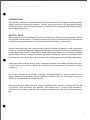
INTRODUCTION:
This manual is intended to assist Authorized Schwinn dealers in identifying and resolving possible
fitness equipment component problems . Dealers should also refer to the appropriate owner's
manuals in order to effectively troubleshoot and understand the operational functions as they pertain to individual products.
HELPFUL HINTS:
Before attempting to troubleshoot an electronic component, a dealer should be equipped with as
many helpful tools as possible. These tools need not be limited to mechanical tools , but should also
include any documented reference material that may be available on a component.
•
Owner's manuals are the most comprehensive source of detailed information on how a component
functions . Oftentimes a dealer will be able to effectively troubleshoot an item simply by knowing its
proper operational functions . Being able to identify legitimate problems vs. a customer's potential
misconception of how a component operates, will help to eliminate the return of non-defective items
to Schwinn , thus saving the dealer the inconvenience of returning parts and ordering replacements.
It would be useful to have a known "good" component on hand as an added troubleshooting tool.
This will help you to verify a problem with a defective item or help trace the problem to another
component.
An AC/DC multimeter is exceedingly helpful as a troubleshooting tool. It can be used for many
things including checking battery voltage, polarity, continuity, current, etc. Multimeters can be purchased at most electronic or hardware stores.
Gather as much information from the customer as possible when they return a component. Ask lots
of questions , "what specifically is the problem", "when does it occur", "how old is the component".
Document the customers' responses and use this information when filling out the "electronic return
tag. "
•
1
TABLE OF CONTENTS
Introduction:
Helpful Hints:
AirDyne, AirDyne Pro, AirDyne Comp, Evolution , Evolution Pro, Evolution Comp:
1. The LCD shows a partial display.
2. The LCD shows no display.
3. No RPM on computer.
4. If you have vibration .
5. If you have squeaking , tapping, rubbing noises.
6. Pedal feels loose.
7. Lever arm feels loose.
8. Connecting arm feels sloppy or loose.
9. Belt squeaking or out of alignment.
Windjammer:
1. The LCD shows a partial display.
2. The LCD shows no display.
3. The computer is on but has no WAITS reading.
4. The RPM's are not working but the WAITS are.
5. The resistance display is not working .
6. The cranks turn , but the fan slips or doesn't move.
7. The resistance crank does not move freely.
Windrigger:
1. The LCD shows a partial display.
2. The LCD shows no display.
3. Inconsistant or no speed reading .
4. The drive feels rough when pulling hard on the handle.
5. There is excessive frame vibration during fan deceleration.
6. The seat carriage is rough or bumping at a fixed point in the rail.
7. The seat carriage is rough or bumping at regular intervals along the track.
8. The rowing handle belt doesn't rewind quickly.
9. The rowing handle belt broke and rewound into the shroud .
Backdraft & Windsprint
1. Computer will not start.
2. Computer does not read properly.
3. No RPM reading .
4. Shifter is hard to turn.
5. Shifter slips into first gear.
6. Will not shift into 5th gear.
7. Belt slips while in 5th gear.
8. If you have vibration.
9. If you have squeaking , tapping , or rubbing noises.
10. Seat lock mechanism (Backdraft) will not hold the seat in place.
2
5
5
6
6
6
7
7
7
7
8
8
9
9
9
10
10
11
11
12
12
•
13
13
13
14
14
15
15
15
16
16
16
16
17
17
17.
TABLE OF CONTENTS
•
PT 105/205 & 105/205/21 Op:
1. Faded or no computer display.
2. The LCD shows a partial display.
3. Inconsistent or no SPEED reading.
4. The resistance belt wears out too quickly.
5. When turning , the flywheel is rough or grinding.
18
18
18
19
19
C1130/230 & 130/230i:
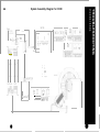
System diagram for C1130/230
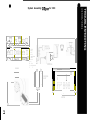
System diagram for 130/230i
1. No computer display.
2. The keyboard does not function .
3. The computer works , but the exerciser provides minimal or no resistance.
4. The computer works , but the exerciser provides only maximum resistance .
5. No STEPS/MIN reading.
20
21
22
23
23
23
24
C1135/235 & 135/235i
System diagram for 135/235i
1. No computer display while pedaling.
2. The keyboard does not function.
3. The computer works , but the exerciser provides minimal or no resistance.
4. The computer works , but the exerciser provides only maximum resistance.
5. No SPEED/RPM reading.
25
26
27
27
27
27
C1130 ,135,230 ,235, & 130,135,230,235i (mechanical)
1. The crank arms feel loose.
2. Grinding or rough operation .
3. The seat locking mechanism won 't keep the position tube in place (recumbents) .
28
28
29
CI330/330i:
System diagram for C1330 .
System diagram for 330i .
1. No computer display.
2. The keyboard does not function .
3. The computer works , but the stepper provides minimal or no resistance.
4. The computer works , but the stepper provides only maximum resistance.
5. No STEPS/MIN reading.
6. Broken pedal spring (large diameter).
7. Broken chain spring (small diameter) .
8. The step pedal is frozen and can 't be moved.
9. Squeaking noises.
30
31
32
33
33
33
34
35
35
36
36
•
3
TABLE
Spinner, Spinner Comp & DX900:
1. The LCD shows a partial display (DX900).
2. Inconsistent or no speed reading (DX900).
3. Squealing brake pads.
4. Vibration in the drive train .
5. The bike is uneven or wobbling .
6. Loose crank arms (Spinner Pro & Comp) .
7. The handlebar or seat post won 't move freely (Spinner Pro &
F
37
37
37
38
38
38
Comp)
Treadmill
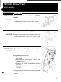
1. A C01 through C07 (communications) error is displayed.
2. An E01 (motor too fast) error code is displayed .
3. An E02 (motor too slow) error code is displayed .
4. An E03 (breakway) error code is displayed.
5. An E04 (no speed input) error code is displayed .
6. The belt does not start and the unit displays an E04.
7. The belt starts up and then stops after a few seconds and displays E04.
8. The display is dead when the power switch is pushed.
9. An E05 (system reset) error code is displayed.
10. An E06 (elevation) error code is displayed .
11 . Elevation is stuck and the display reads E06 .
12. Elevation is stuck and the display reads E06 (continued).
13. Elevation will not go all the way up or all the way down .
14. The treadmill needs to be recalibrated often.
15. Elevation only goes in one direction.
Weightstack
1. The action of the machine feels rough on one station or movement.
2. The action of the machine feels rough on all stations.
3. The weight selector pin doesn't insert into the plates .
4. The cables are twisting.
5. The cable is jumping off the pulley.
6. The cable is too short.
•
39
40
40
40
41
41
42
43
43
44
44
45
46
47
47
47
48
48
49
49
49
49
•
4
TROUBLESHOOTING
•
AIRDYNE, AIRDYNE PRO, AIRDYNE COMP, EVOLUTION,
EVOLUTION PRO & EVOLUTION COMP
ELECTRONIC
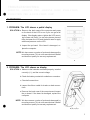
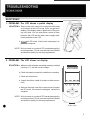
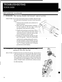
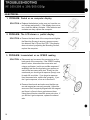
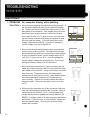
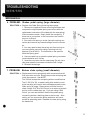
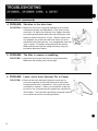
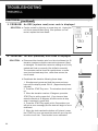
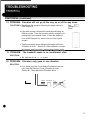
1. PROBLEM: The LCD shows a partial display
SOLUTION: a. Remove the back case of the computer and press
on the back of the LCD to see if you can get a full
display. If the display returns , tighten the LCD mounting screws until fixed. You can also place a piece of
foam between the LCD and the back case to apply
additional pressure on the LCD .
II
I
b. Inspect the pc board. if the board is damaged , replace the computer.
NOTE: We have seen a number of pc boards damaged by
mounting screws. This is not a manufacturer's defect
and does not qualify for warranty replacement.
a
2. PROBLEM: The LCD shows no display
SOLUTION: a. Make sure the batteries are seated properly, installed
correctly (+/-) , and the correct voltage.
b. Check the battery contacts for oxidation or corrosion .
c. Check all connections.
d. Inspect the ribbon cable for breaks or bad connections.
e. Remove the back case of the computer and inspect
the pc board . If the board is damaged , replace the
computer.
•
NOTE: We have seen a number of pc boards damaged by
mounting screws. This is not a manufacturer's defect
and does not qualify for warranty replacement.
a,b,c,d,e
5
TROUBLESHOOTING
AIRDYNE, AIRDYNE PRO, AIRDYNE COMP, EVOLUTION,
EVOLUTION PRO & EVOLUTION COMP
ELECTRONIC (continued)
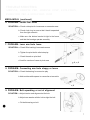
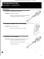
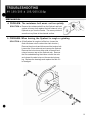
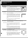
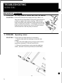
3. PROBLEM: No RPM reading
SOLUTION: a. Check all connections.
b. Remove the sensor from the mounting bracket and
pass a hand held magnet over the surface of the sensor. If a signal is received , remount the sensor and
make sure the gap between the flywheel magnet and
the sensor is between 2 and 4mm .
c. If no signal is received , use a multimeter to check the
continuity of the sensor and then the sensor wire. If
both the sensor and wire are functioning , replace the
computer.
MECHANICAL
PROBLEM: If you have vibration
SOLUTION: a. Reduce belt tension by first loosening the axle nuts
and then loosening the tensioner nuts.
b. Check the hub bearing for rough operation
a
5. PROBLEM: If you have squeaking, tapping or rubbing noises
SOLUTION: a. Check chain tension - tighten or loosen
b. Order new tension device - updated wheel type
c. Lube chain
d. Lube pivot points
e. Align the belt using the fan tensioner
f. Check all bearings for binding or play
g. See if fan is rubbing cage
6
b
•
TROUBLESHOOTING
AIRDYNE, AIRDYNE PRO, AIRDYNE COMP, EVOLUTION,
EVOLUTION PRO & EVOLUTION COMP
MECHANICAL (continued)
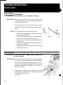
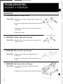
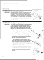
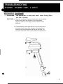
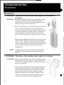
6. PROBLEM: Pedals feel loose
SOLUTION: a. Check cotter pins for looseness or excessive wear.
b. Check chain ring to ensure that it hasn't separated
from the right eccentric.
c. Make sure the bottom bracket is tight in the frame
and that the bearings operate smoothly.
~
a ,b
7. PROBLEM: Lever arm feels loose
SOLUTION: a. Check Olite bushing for excessive wear
b. Tighten the pivot bolt to eliminate play
c. Check threads on pivot bolt
d. Look for cracks on frame at pivot area
a,b,c,d
8. PROBLEM: Connecting arm feels sloppy or loose
SOLUTION: a. Check the bearing for excessive play
b. Add another white spacer to connection at eccentric
a,b
9. PROBLEM: Belt squeaking or out of alignment
SOLUTION: a. Adjust tension and alignment at fan hub
b. Adjust cam washer at idler hub to align the belt
•
c. Put belt dressing on belt
a
7
ELECTRONIC
1. PROBLEM: The LCD shows a partial display
SOLUTION: a. Remove the back case of the computer and press
on the back of the LCD to see if you can get a full
display. If the display returns , tighten the LCD mounting until fixed . You can also place a piece of foam
between the LCD and the back case to apply additional pressure on the LCD.
b. Inspect the PC board . If the board is damaged , replace the computer.
NOTE: We have seen a numberof PC boards damaged by
mounting screws. This is not a manufacturer's defect
and does not qualify for warranty replacement.
a,b
2. PROBLEM: The LCD shows no display
SOLUTION: a. Make sure the batteries are seated properly, installed
correctly (+/-), and the correct voltage.
b. Check the battery contacts for oxidation or corrosion.
c. Check all connections.
d.lnspect the ribbon cable for breaks or bad connections.
e. Remove the back case of the computer and inspect
the PC board . If the board is damaged , replace the
computer.
NOTE: We have seen a number of PC boards damaged by
mounting screws. This is not a manufacturer's defect
and does not qualify for warranty replacement.
a,b,c,d,e
8
•
ELECTRONIC
(_co_n_t_in_u_e_d.L..~
_
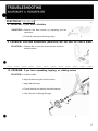
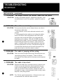
3. PROBLEM: The computer is on but has no WATTS
reading
SOLUTION: a. Using a volt meter, test the continuity of the fan sensor and fan sensor wire. If either is bad , replace it.
a
4. PROBLEM: The RPM's are not working but WATTS are
SOLUTION: a. Using a volt meter, test the continuity of the crank
sensor and the crank sensor wire. If either is bad ,
replace it.
a
5. PROBLEM: The resistance display is not working
SOLUTION: a. Make sure the two prong plug is securely plugged
into the back of the computer.
b. Recalibrate the resistance by:
1. Turning the resistance crank counterclockwise
until it stops.
2. Simultaneously pressing the "ENTER" and
"MANUAL" keys.
3. Pressing the "RACE" key, and then pressing
"ENTER".
4. Turning the crank to full resistance and pressing
"ENTER".
•
c. Using a volt meter, test the continuity of the sensor
wire. If the wire is good , replace the Slide Potentiometer.
a
9
MECHANICAL
6. PROBLEM: The cranks turn, but the fan slips or
doesn't move
SOLUTION: a. Remove the shroud and make sure both belts are on
the pulleys.
b. lf the cogged belt turns and the V-belt doesn't, replace the intermediate hub shaft.
7. PROBLEM: The resistance crank does not move freely
SOLUTION: a. Remove the shroud and make sure the threads on
the lead screw are not damaged. If the lead screw is
undamaged , grease the threads.
b. Remove the resistance mechanism by removing the
stop blocks. Replace any parts that do not slide freely
on the lead screw.
NOTE: During reassembly, keep in mind thatthe lead screw
has a left hand thread on one end and a right
hand thread on the other. Also , the right handed
pulley block (resistance handle side of the lead screw)
has a hole on top to accept the slide potentiometer.
a,b
•
10
ELECTRONIC
1. PROBLEM: The LCD shows a partial display
SOLUTION: a. Remove the back case of the computer and press
on the back of the LCD to see if you can get a full
display. If the display retums, tighten the LCD mounting until fixed. You can also place a piece of foam
between the LCD and the back case to apply additional pressure on the LCD .
b. Ir)spect the PC board . If the board is damaged , replace the computer.
NOTE: We have seen a number of PC boards damaged by
mounting screws. This is not a manufacturer's defect
and does not qualify for warranty replacement.
a,b
2. PROBLEM: The LCD shows no display
SOLUTION: a. Make sure the batteries are seated properly, installed
correctly (+/-), and the correct voltage.
b. Check the battery contacts for oxidation or corrosion.
c. Check all connections.
d. Inspect the ribbon cable for breaks or bad connections.
e. Remove the back case of the computer and inspect
the PC board. If the board is damaged , replace the
computer.
NOTE: We have seen a number of PC boards damaged by
mounting screws. This is not a manufacturer's defect
and does not qualify for warranty replacement.
•
a,b,c,d,e
11
ELECTRONIC
3. PROBLEM: Inconsistent or no speed reading
SOLUTION:a. Remove the left shroud (see note) and make sure
the gap between the fan sensor and fan magnet is
between 2mm and 4mm .
b. Using a volt meter, test the continuity of the sensor
wire. If the sensor wire is functioning , replace the computer.
NOTE: To remove the shrouds, follow these steps:
1. Remove the right shroud mounting screws (not
the crash plate screws) .
2. Remove the right crash plate screws while holding onto the nut plate inside the shroud.
3. Remove the left shroud screws except the top
corner screw.
4. Remove the left crash plate screws while holding onto the nut plate.
5. Keep the handle and crash plate connected and
remove the shrouds.
a,b
MECHANICAL
4. PROBLEM: The drive feels rough when pulling hard
on the handle
SOLUTION:a. Remove the shrouds (see previous note) and tighten
the V-belt at the fan using the fan tensioners. Tighten
the belt just until the slipping stops (belt tension. measured on a belt tension gauge #91348 , should be
between 85 and 95 Ibs). Replace the V-belt if it is
glazed or cracked .
b.lf tightening or replacing the V-belt doesn't correct
the problem , the roller clutch is slipping on the drive
axle. Replace the drive axle
assembly.
a
12
•
MECHANICAL (continued)
5. PROBLEM: There is excessive frame vibration during
fan deceleration
SOLUTION: a. Make sure the four bolts that attach the rail to the frame
are tight.
b.Check for bad belt alignment, an overtensioned belt,
or bad fan bearings .
6. PROBLEM: The seat carriage is rough or bumping at
a fixed point in the rail
SOLUTION: a.Remove the seat assembly and clean the ra il track
with a long handled screwdriver and a rag.
a
7. PROBLEM: The seat carriage is rough or bumping at
regular intervals along the rail track
SOLUTION: a.lnspect both the vertical and horizontal wheels. If a
wheel is rough , replace it.
NOTE: When reinstall ing the seat carriage assembly, the
wheels should fit snugly in the seat rail. If the fit is too
tight or too loose (the carriage has has enough clearance to rock in the ra il track), you can tune the fit by
moving the middle vertical wheel up or down . Bear in
mind that the seat assembly may feel too tight until
you are actually sitting on the seat and rowing .
•
a
13
MECHANICAL (continued)
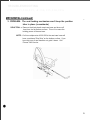
8. PROBLEM: The rowing handle belt doesn't rewind quickly
SOLUTION: a.lt is likely that a belt spring has failed. Replace both
the right and left springs using the following guidelines:
1. Remove the shrouds (see previous for
shroud removal.
2. Make sure the rowing handle is resting in
the two hooks on the fan cage or the
springs will not be wound correctly.
3. Replace the springs one at a time. When
removing the last of the three allen head /
mounting screws, hold the spring case
with one hand so it doesn't spin .
4. Keeping in mind that the springs are right
and left specific, follow the directions
printed on the spring casing with one important exception . Prewind the springs
in the direction of the arrow between
3 to 3 1/2 turns (not the 1 to 11/2 turns
printed on some labels).
a
9. PROBLEM: The rowing handle belt broke and
rewound into the shroud
SOLUTION: a. Replace the belt (and the belt springs, see previous)
using a screwdriver to release the old belt by turning
the belt holding cam. Install the new belt under the
cam making sure that the free end of the belt does
not extend above the wrapping surface of the flat belt
pulley. Wrap the belt in the direction of the arrow on
the flat belt pulley.
•
14
ELECTRICAL
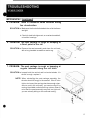
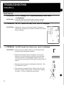
1. PROBLEM: Computer will not start
SOLUTION: a. Replace the batteries .
b. Make sure the gap between the sensor and the flywheel magnet is between 2 and 4mm.
b
2. PROBLEM: Computer does not read properly
SOLUTION: a. Check all cennections.
b. Make sure the proper elevation is entered .
a
3. PROBLEM: No RPM reading.
SOLUTION: a. Make sure the gap between the sensor and the
flywheel magnet is between 2 and 4mm .
b. Inspect the sensor wires for any breaks.
c. Check all connections.
•
a
15
ELECTRICAL
4. PROBLEM: Shifter is hard to turn
SOLUTION: a. Make sure the up/down toggle switch is being used
correctly.
b. Loosen the cable stops to allow the cable to move
freely.
c. Lubricate the cable and remove any tight bends in
the housing.
d. Replace the cable.
a
5. PROBLEM: Shifter slips into first gear
SOLUTION: a. Make sure the toggle switch pin is centered in the
shifter housing.
a
6. PROBLEM: Will not shift into 5th gear
SOLUTION: a. Reduce the belt tension by adjusting the fan
tensioners.
b. Loosen the cable stops to allow the cable to move
freely.
a
7. PROBLEM: Belt slips while in 5th gear
SOLUTION: a.lncrease the belt tension by adjusting the fan
tensioners.
b.Tighten the cable stops until the belt quits slipping.
a
16
•
ELECTRICAL (c_o_n_t_in_u_e_d..1
..
_
8. PROBLEM: If you have vibration
SOLUTION: a. Reduce the belt tension by adjusting the fan
tensioners.
b. Check all bearings for binding or play.
a
9. PROBLEM: Seat lock mechanism (backdraft) will not hold the seat in place
SOLUTION: a. Replace the current cam block with the urethane
backed version .
•
-----------10. PROBLEM: If you have squeaking, tapping, or rubbing noises
SOLUTION: a. Lube the chain.
b.Align the belt using the fan tensioners .
c. Apply belt dressing .
d. Check the hub and bottom bracket bearings.
e. See if the fan is rubbing the cage .
•
d
17
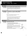
ELECTRICAL
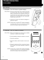
1. PROBLEM: Faded or no computer display
SOLUTION: a. Replace the batteries (make sure you have the correct voltage and polarity). If the display does not return , clean the battery contacts. If the batteries and
contacts are okay, replace the computer.
2. PROBLEM: The LCD shows a partial display
SOLUTION: a. Remove the back case of the computer and tighten
the Mounting Screws to ensure a proper connection between the LCD and the PCB. If the display
does not return by adjusting the Mounting Screws,
replace the computer.
3. PROBLEM: Inconsistent or no SPEED reading
SOLUTION: a. Disconnect and reconnect the sensorwire on the
back panel of the computer. If the SPEED reading
doesn't return , disconnect the sensor wire and
using a multimeter (set for an audible response if
available) test the wire by placing your probes on
each of the two sensor wire pins. Slowly turn the
cranks and you should get a response (beep) once
for each full revolution. If you do get a response
from the sensor/wire, replace the computer. If you
don't get a response , move on to Section B.
b. Remove the shrouds and make sure that the sensor and magnet are securely mounted . Adjust the
sensor so that it's squarely aligned with the magnet
and there's a 2mm to 4mm gap between them.
Using the multimeter, retest the sensor wire pins. If
you still don't get a response , replace the sensor/
wire.
b
•
18
MECHANICAL
(i)
4. PROBLEM: The resistance belt wears out too quickly
SOLUTION: a. Remove the resistance belt from the flywheel and hold
a piece of emery cloth against the belt channel in the
flywheel as you turn the cranks. The emery cloth will
smooth out any flaws in the channel surface.
@
5. PROBLEM: When turning, the flywheel is rough or grinding
SOLUTION: a. (If the flywheel is rough out of the box, loosen the
chain tensioner nuts to reduce the chain tension.)
Remove the shrouds and disconnect the tension belt.
Loosen the 15mm axle nuts and remove the flywheel.
Remove the locknuts on either side of the axle and ,
using a hammer, tap out the flywheel axle. Remove
the one sealed bearing that came out with the axle
and reinsert the axle to tap out the remaining bearing. Replace the bearings and replace the axle if it
is damaged .
•
19
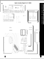
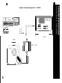
System Assembly Diagram for CI 130/230
I\.)
o
n
K
~OO~
4
U
;O
1
I
::E3
I
D
1
3
c:eJI
. . .
2
•
1 3
FUNCT ION
3
. _
u
D
A
J
u
_
. u::- .
. _
I
1
_.
3
I
.
_ .
l.
4
o
o
D
II
G
~c=:[IJl
A
- D
B
- E
MrTF
o
[
o
o
P
g
g
o 0
C -- F
G
I
K
- II
D
]
o
o
DAD
0\70
J
M[T[R
K
BRAK
SPEED
SENSOR
~
01111111 1111
1111111[1110
Cl
o
L-
o
CONTROL UNIT
~
ABC
o
D
E
F
G
H
RED
o
ADAPTER
[lLACK
C)
J
0
AC ADAPTER
•
System Assembly Diagram for 130/230i
~
1 3
N
o
~LJ
.l
G
H
]I
A
METER
B--E
C--F
G
- H
K - -METER
L--M
N--O
P
BRAKE"
D
o
o
o
o
o
i--l
o
o
~
o 0
o
o
0
0
D
LJ6D
[lvD
'----
--I
'---K
0
S--R
Sf,)EE..D
T--CROUND
SENSOR
[ClJB
Q
L
o
D
o
MI
N P
ADAPTOR
--~
o
o
CONIROL UNI T
~=t
o
0000000
DDDDODO
000000
C
o
C)
I'V
......
.'1
0000000
( r
Ii
III
R
-A
-- ~
0
III
c:::::::J
I
I
10
s
ELECTRONIC
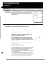
1. PROBLEM: No computer display
SOLUTION: a. Disconnect and reconnect the computer wire on the back
panel of the computer. If the display does not retum , disconnect the computer wire and , using a multimeter, verify that
5.5 volts (D .C.V plus or minus 5%) are coming up from the
controller by placing your probes on pins one (black) and
four (red). If you are getting the correct voltage, replace the
computer.
K
tool
4
NO. COLOR
1
BLACK
WH I TE
2
GREEN
3
4
RED
1
FUNCTIOl\
GROUND
SPEED
D/A OUT
+5v
a
b.lf the correct voltage is not passing through the computer
wire , make sure that power is getting to the controller by:
(Older CI1301230 units) verifying that a voltage range of
12-20 D.C.V is getting through the NC adapter. Disconnect the NC adapter from the exerciser and place one
multimeter probe on the outside metal casing of the plug
end and the other probe inside the plug end hole. If the
voltage is outside the specified range , replace the NC
adapter. If the voltage is okay, move on the Section C.
(Newer 1301230i units) verify that the on/off switch is lit.
If the switch is not lit open the fuse door by the on/off
switch and make sure the fuse isn't blown. If the fuse is
okay, disconnect the external power cable from the exerciser and , using a multimeter set on volts NC
(VA.C.) ,verify that 110 volts are passing from the wall
through the cable. If the fuse and voltage are okay, replace the on/off switch .
If the on/off switch is lit, remove the shrouds and verify that
a voltage range of 12-20 D.C .V is getting through the NC
adapter by placing your multimeter probes on each of the
two connecting contacts between the adapter and the
controller. If the voltage is outside the specified range ,
replace the NC adapter. If the voltage is okay, move on to
Section C.
c. Disconnect and reconnect the computer wire at the controller. If the connection is okay, use a multimeter to test
the computer wire continuity (against pinch breaks caused
by the computer mast) by placing the probes on corresponding upper and lower wire pins. (Red wire pin to red
wire pin , etc.) If the wires are functional , replace the
controller.
22
I
I
J
ce=J[
2
S
3
No.1 COLOR I FUNCT ION
1(+1 3.5V)
1 I RED
2 IBLACK I GROUND
b
E
D
B
EJ
2
2
NO. COLOR FUNCT ION
1
BLACK GROUND
(+13.5V)
RED
2
b
~
ABC
D E F
c
•
ELECTRONIC (continued)
2. PROBLEM: The keyboard does not function
D
0
SOLUTION: a. Remove the computer and take off the back panel. Make
sure the ribbon cable is properly connected . If the keyboard function does not return by reconnecting the ribbon
cable , replace the computer.
0
0
0
I
0
I
sr=?
D
D
D~D
OV"O
D
D
-
3. PROBLEM: The computer works, but the exerciser provides minimal or no
resistance
SOLUTION: a. Disconnect and reconnect the computer wire on the back
panel of the computer. If the resistance doesn't change , disconnect the computer wire and , using a multimeter, verify
that 5.5 volts (D .C.V. plus or minus 5%) are coming up from
the controller. If you are getting the correct voltage , move on
to Section B. If you don't get the correct voltage , follow the
steps outlined in no computer display, Section C .
K
tDDDl
4
1
NO. COLOR
1
BLACK
WHI TE
2
GREEN
3
4
RED
FUNCTIO~
GROUND
SPEED
D/A OUT
+5v
a
b. Remove the shrouds and disconnect, then reconnect the
electromagnetic brake wire from the controller. If the resistance doesn't change , disconnect the mag brake wire from
the controller and , using a multimeter, check the controller
pins for a voltage output range between 12-20 D.CV. If the
voltage is in the specified range , replace the electromagnetic brake . If the voltage is not within the range , replace
the controller.
0
A
D
EJ
3
1
3
No.1 COLOR I FUNCT ION
1 1RED
1CO Il
3 I RED I CO Il
b
4. PROBLEM: The computer works, but the exerciser provides only maximum resistance
SOLUTION: a. Disconnect the computer wire from the back of the computer. If the resistance level changes , replace the computer. If the resistance level doesn't change , move on
Section B.
•
b. Remove the shrouds and disconnect both the computer
wire and the electromagnetic brake wire from the controller. If the resistance level changes , replace the controller. If
the resistance level doesn't change , replace the brake.
iI
8
h?
~ ~
o
I
Dl'D
D'VD
~.
a
j~~E)!t
A
•
C
DE'
i~
b
23
ELECTRONIC (continued)
5. PROBLEM: No Speed/RPM reading
SOLUTION: a. Disconnect and reconnect the computer wire at the back of
the computer. If the speed/RPM function doesn't return ,
move on to Section B.
(Optional if you have a second computer on hand, plug it in
to see if you get a reading. If so. replace the computer.)
o
i 1,--__
8
P
!!
D L7l. D
D 'V D
~.
a
b. Disconnect the computer wire from the back of the computer and , using a multimeter, check for continuity by placing the probes on the number one (black) and number two
(white) connector pins and slowly turning the pedals. This
method works best with the multimeter set to an audible
response. The multimeter should beep each time the
magnet passes the sensor. (Make sure that the magnet is
securely in place). If the multimeter does respond when the
magnet passes the sensor, replace the computer. If the
multimeter doesn't respond when the magnet passes the
sensor, replace the sensor and wire.
K
tODOl
4
1
NO . COLOR
1
BLACK
IWHI TE
2
GREEN
3
L
RED
FUNCT I O~
GROUND
SPEED
D/A OUT
+sv
b
•
24
•
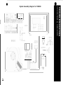
System Assembly Diagram for 135/235i
~I~~~I,~J
'B
2'
D'
2
~Dr
]
1
I
O_c=J~
8
0
mllmm
88818188188
A-
D
SCHWINN
B- E
,-=
C-F
G--H
K--ME1ER
oe=C:j
o
BRAKE
~
o
CONTROL UNIT
o
~
o
c:>
tv
01
c:>
o
o
QQ
~
II
o
f
6) 0
0( c:::J 0)
o
o
0
Q
0
0
0
==- ,
METER
c
o
0
o
o
~
1
0
00
0
,
ELECTRONIC
1. PROBLEM: No computer display while pedaling
SOLUTION: a. Have someone pedaling throughout the following steps. If
the computer displays a battery icon, replace the batteries. Disconnect and reconnect the computer wire on the
back panel of the computer. If the display does not return ,
disconnect the computer wire and , using a multimeter,
verify that 5.5 volts ( D.C.V plus or minus 10%) are coming up from the controller by placing your probes on pins
one (red) and five (black). If you are getting the correct
voltage, replace the computer. If you aren 't getting the
correct voltage, move on to Section B.
b. Remove the shrouds and disconnect then reconnect the
computer wire at the controller. If the connection is okay,
disconnect the wire and use a multimeter to check controller pins one and five for the correct voltage output of 5.5
volts (D.C.V plus or minus 10%). If you are getting the
correct voltage, replace the computer wire. If you aren 't
getting the correct voltage , move to Section C.
c. Disconnect the generator wire (2 pin connector) and the
brake wire (3 pin connector) that run from the electromagnetic brake to the controller. Using a multimeter, check the
wire continuity. The generator wire should provide a
resistance of 3 ohms (plus or minus 1 ohm) and the brake
wire should provide a resistance of 13 ohms (plus or
minus 3 ohms). If either wire is bad , replace the electromagnetic brake . If the wires are good , move on to Section D.
d. Disconnect the generator wire (2 pin connector) that runs
from the electromagnetic brake to the controller. Using a
multimeter set on volts AlC (VA.C.) , test the generator
voltage while someone pedals at a normal cadence (60
RPMS) . A voltage output of 10 volts or greater indicates a
good brake. If you don't get 10 volts or better, replace the
electromagnetic brake, If you do get 10 volts or more,
replace the controller.
26
K
4
Ll
NO . COLOR
1
BLACK
WH I TE
2
GREEN
3
4
RED
1
FUNCT IOf\
GROUND
SPEED
D/A OUT
+SV
a
~I
C
G
5
1
5
NO. COLOR FUNCT 0/\
1
RED
-.-5 V
GREEN D A OU
2
3
4
5
WHITE SPFE
I BLACK GROUND
b
c
d
•
ELECTRONIC (continued)
2. PROBLEM: The keyboard does not function
SOLUTION: a. If the computer displays a battery icon, replace the batteries. Remove the computer and take off the back panel.
Make sure the ribbon cable is properly connected. If the
keyboard function does not return by reconnecting the
ribbon cable. replace the computer.
I_ Per='
S~N ~~ ~
I
a
3. PROBLEM: The computer works, but the exerciser provides minimal or no resistance
SOLUTION: a. Remove the shrouds and disconnect the computer wire at
both the computer and the controller. Using a multimeter.
check the continuity of each of the four wires. If any of the
wires are bad , replace the wire harness. If the wires are
good , reconnect the computer wire and move on to Section B.
a
b. Follow the steps outlined in NO COMPUTER DISPLAY
WHILE PEDALING, Sections C and D.
4. PROBLEM: The computer works, but the exerciser provides only
maximum resistance
SOLUTION:a . Disconnect the computer wire from the back of the computer. If the resistance level changes , replace the computer. If the resistance level doesn't change, move on to
Section B.
---~
a
b. Remove the shrouds and disconnect both the computer
wire and the electromagnetic brake wire from the controller. If the resistance level changes , replace the controller.
If the resistance level doesn't change , replace the brake.
5. PROBLEM: No SPEED/RPM reading
SOLUTION: a. If you have a second computer on hand , plug it in to see if
you get a reading . If so, replace the computer.
•
b. Check all connections and continuities, following the steps
outlined in NO COMPUTER DISPLAY... , Section C and
THE COMPUTER WORKS BUT PROVIDES MINIMAL. .., Section A. If all wires and connections are good ,
replace the controller.
-
o
o
-
-
o
o
-
27
TROUBLESHOOTING
CI130,135,230,235, & 130,135,230,235i
MECHANICAL
1. PROBLEM: The crank arms feel loose
SOLUTION: a. Remove the suspect crank arm and make sure that the
squared surface that contacts the crank shaft hasn't
rounded out. If the crank arm is okay, slide it back on the
crank shaft and torque the crank bolts to 25 foot pounds.
(300 inch pounds, or 35 Newton meters). If the crank arm
is damaged , replace it and torque the crank bolts to the
above specification.
2. PROBLEM: Grinding or rough operation
SOLUTION: a. This is usually due to a bad bearing in one of three areas.
At first, remove the crank arms and shrouds and try to
pinpoint the problem. Replace a crank arm and turn the
crank to look for bad belt alignment and listen for bad
bearings. If you can 't pinpoint the source, move on to the
specific bearing areas.
1. Crank shaft bearings. Remove the Crank Arms
and the Poly-V Belt (or chain) from the Crank Pulley
(sprocket). Rock the crank shaft by hand to see if
there is excessive play caused by bad bearings.
Rotate the crank shaft and feel for any grinding or
rough operation, If the bearings have failed , replace
the Crank Pulley Assembly (bearings) .
2. Mid Hub assembly. Remove both belts (Belt &
Chain) and rock the Mid Hub Flywheel by hand to see
if there is excessive play caused by bad bearings.
Rotate the Flywheel to feel and listen for any grinding
or rough operation. If the bearings have failed , replace
the Mid Hub Assembly (bearings).
2
3. Electromagnetic brake bearings. This is the least
likely ofthe three bearing failures. Remove the belt
and rotate the disc by hand while listening for any
grinding .
3
28
•
TROUBLESHOOTING
CI130,135,230,235, & 130,135,230,235i
MECHANICAL(_co_n_t_;n_u_e_d..L..~
_
3. PROBLEM: The seat locking mechanism won't keep the position
tube in place (recumbents)
SOLUTION: a. Remove the black plastic seat cam base and shave off
1mm from the flat bottom surface. This will increase the
holding power of the seat cam.
NOTE: On future shipments of 230/235i's the seat cam base will
have a urethane "Grip Strip" on the bottom surface. If you
have this type of cam base do not grind it down . Call
Fitness Tech Service.
•
29
VJ
System Assembly Diagram for CI330
a
METER
o 0
----rrr-
SPEED
SENSOR
BLACK
RED
I
1m
011111 111111
Iii
11111111111 0 1
...
OVU
cg4
-
L-
III
A
D
-c
-D
- - G
-
II
J
L
M[T ER
I
011111111111
111111111110 1
K
M
III
CONTROL UNIT
All
C
A
EJ LJ
2 1
~31dvav ::lvi
I
2
1
F N TIN
N RAT
GENERATOR
1 3
D6[J
go g0
H
lb=L~f
I
h;J
o
o
G H
~UU~U
I
RED
BLACK
~
~D
J
N
1
3
•
R
RED
D
g
o
o
o
o
o
o
"
r
r NCT ION'
I
COl
1
I-
C
•
System Assembly DiJQram for 330i
K
Ll
4
;:r
T
a
,
, J
F
I if, A
I T I SP LQ
1
~
c
J
F
I
I
N
D
J
"
F
A
ttl
,.
Q
~
-
"
-0
A
EJ
2
,
U
J
I
C
8
1
I
H
D
o~~
.
,
2
K
1RFI
C
I
TI
,V
,
I
IWHI
I<p
V
u
EJ
2
I
,
D,
2
N
,
IRIW
•
:~
A--D
B--E
C--F
G--H
L
a
K--METER
L--M
N--O
p--
0
00
a
a
0
N P
D
O~
"~O
DOD
ODD
0
o
0
Q
0
ADAPTOR
S--R
T--GROUND
BRAKE
U
V
u
t5
o
o
0
0
0
0
0
CONTROL
UNIT
o
0
0
o
o
gq
o
A
8
o
E
-
r--
(j
]
I
P
o
o
o
D6D
DvD
0
0
0
I--
L.......
-
-
--
METER
o
c:>
w
......
D
ELECTRONIC
1. PROBLEM: No computer display
SOLUTION: a. (After making sure that the computer rear panel switch is
ON). Disconnect and reconnect the computer wire on the
back panel of the computer. If the display does not return ,
disconnect the computer wire and , using a multimeter,
verify that 5.5 volts (D.C.V plus or minus 5%) are coming
up from the controller by placing your probes on pins one
(black) and four (red). If you are getting the correct voltage,
replace the computer.
b. If the correct voltage is not passing through the computer
wire , make sure that power is getting to the controller by:
(Older CL330 units) verifying that a voltage range of 1220 D.C .V is getting through the AlC adapter. Disconnect
the AlC adapter from the exerciser and place one multimeter probe on the outside metal casing of the plug end and
the other probe inside the plug end hole. If the voltage is
outside the specified range , replace the AlC adapter. If
the voltage is okay, move on to Section C.
(Newer 330i units) verifying that the ON/OFF switch is lit.
If the switch is not lit open the fuse door by the ON/OFF
switch and make sure the fuse isn't blown. If the fuse is
okay, disconnect the external power cable from the exerciser and , using a multimeter set on volts AlC (VA.C.) ,
verify that 110 volts are passing from the wall through the
cable. If the fuse and voltage are okay, replace the ON/
OFF switch.
If the ON/OFF switch is lit, remove the shrouds and verify
that a voltage range of 12-20 D.C.V is getting through the
AlC adapter by placing your multimeter probes on each of
the two connecting contacts between the adapter and the
controller. If the voltage is outside the specified range ,
replace the AlC adapter. If the voltage is okay, move on to
Section C.
c. Disconnect and reconnect the computer wire at the controller. If the connection is okay, use a multimeter to test
the computer wire continuity (against pinch breaks caused
by the computer mast) by placing the probes on corresponding upper and lower wire pins. (Red wire pin to red wire pin , etc. if the wires are functional replace the controller.
32
4
1
No.1 COLOR I FUNCT I O~
1 I S,-ACK GROUND
WHITE SPEED
2
3 I GREEN D/A OUT
4
RED
-5V
a
K
L
2
~
v
I
2
2
I--::----'''-=f-'='-'----''''-'-':'-'''-~___l
b
c
ELECTRONIC (continued)
2. PROBLEM: The keyboard does not function
o
o
SOLUTION: a. Remove the computer and take off the back panel. Make
sure the ribbon cable is properly connected . If the keyboard function does not return by reconnecting the ribbon
cable , replace the computer.
g
o
g
a
3. PROBLEM: The computer works, but the stepper provides minimal or no
resistance ( fastest step rate)
SOLUTION: a. Disconnect and reconnect the computer wire on the back
panel of the computer. If the resistance doesn't change ,
disconnect the computer wire and , using a multimeter,
verify that 5.5 volts (D.C.V. plus or minus 5%) are coming
up fro the controller. If you are getting the correct voltage,
move on to Section B. If you don't get the correct voltage,
follow the steps outlined in No Computer Display, Section
C.
r.=.
a
b. Remove the shrouds and disconnect the mag brake wire
from the controller and , using a multimeter, check the
controller pins for a voltage output range between 12-20
D.C.V. If the voltage is in the specified range , replace the
electromagnetic brake , If the voltage is not within the
range , replace the controller.
J
[
~
b
4. PROBLEM: The computer works, but the stepper provides only maximum
resistance (slowest step rate)
SOLUTION: a. Disconnect the computer wire from the back of the computer. If the resistance level changes , replace the computer. If the resistance level doesn't change , move on to
Section B.
g
D.
IT
\l
a
•
b. Remove the shrouds and disconnect both the computer
wire and the electromagnetic brake wire from the controller. If the resistance level doesn't change , replace the
brake.
c
0
0
0
I
0
b
33
ELECTRONIC
(_co_n_t_in_u_e_d.L..~
_
5. PROBLEM: No STEPS/MIN reading
SOLUTION: a. Disconnect and reconnect the computer wire at the back
of the computer. Ifthe STEPS/MIN function doesn't return ,
move on to Section B. (Optional if you have a second
computer on hand , plug it in to see if you get a reading. If
so, replace the computer.)
b. Disconnect the computer wire from the back of the computer and, using a multimeter, check for continuity by
placing the probes on the number one (black) and number
two (white) connector pins and slowly turning the pedals.
This method works best with the multimeter set to an
audible response. The multimeter should beep each time
the magnet passes the sensor (make sure that the magnet
is securely in place). If the multimeter does respond when
the magnet passes the sensor, replace the computer. If
the multimeter doesn't respond when the magnet passes
the sensor, replace the sensor & wire .
NOTE:
8IT
o
0
O.6C
c'V~
'---i
.~--l
L-'
a
2
3
b
The flywheel on the 330 contains eight magnets. Therefore , for one revolution of the flywheel, the multimeter
should beep eight times. A misaligned sensor could
double trip causing sporadic readings. If this occurs try to
realign the sensor with the magnets.
•
34
MECHANICAL
6. PROBLEM: Broken pedal spring (large diameter)
SOLUTION: a. Replace the Pedal Spring following these steps :
1. Remove the upper and lower mounting hardware and
compare the original pedal spring connectors with the
replacement connectors (If included with the new spring)
If the connectors match , simply install the new spring . If
there are no connectors , or the connectors don't match ,
move on to Step 2 .
2. Secure the old spring in a vise (below the spring connector) and remove any brass bushings from the connector.
3. You may need to keep the spring end from turning as
you unscrew the connector using a pivoting lock ring
spanner (Part #74412). The hook end on the spanner
holds the Spring open.
4. Use a screwdriver to rotate the pedal spring connector
counterlockwise until it's free.
5. Insert the connector into the new spring (Do not use a
vise) and rotate the connector clockwise until it's tight.
6. Reinstall the springs.
a
7. PROBLEM: Broken chain spring (small diameter)
SOLUTION: a. Replacement chain springs ship with connectors that will
fit all connector mounts. Simply remove the old spring and
install the new one. See NOTE.
The 330i will accept the new spring without modifications.
The CI 330 (Pre '96 , or models with white and blue computer overlays) will need to be modified because the new
chain spring is longer. Remove two half links from the
chain using a 3/16" Dia. Drift Punch (or a motorcycle chain
tool) to punch outthe chain pin . If you are using a Drift
Punch , you can use the Allen Head of the pedal spring
connecting bolt as a backing plate to start the pin . Alternately, you can remove the entire pedal arm and use a
socket as a backing plate. Reattach the new spring using
the masterlink.
•
a
35
MECHANICAL (continued)
8. PROBLEM: The step pedal is frozen and can't be moved
SOLUTION: a. Remove the shrouds and inspect the Poly V Belts. It's
likely that the belt has shifted off the pulley grooves and is
pushed up against the bearing housing. Shift the belt
back into position and make sure that the belt tensioning
pulley is centered on the belt. A misaligned tensioner will
keep pushing the belt off track, so you will have to bend
the tensioner arm until the pulley is centered .
a
9. PROBLEM: Squeaking noises
SOLUTION: a. There are three areas that may be squeaking :
1. Treat the belts with belt dressing to eliminate belt
squeak.
2. Spray the lower pedal spring connector mount with a
spray lube (Schwinn Fit Tech is Part #72016)
3. Remove the pedal arms and grease the pedal arm
shafts. (Schwinn Team Shop Grease is Part #72002).
•
36
ELECTRONIC
1. PROBLEM: The LCD shows a partial display (DX900)
SOLUTION: a. Remove the back case of the computer and press on the
back of the LCD to see if you can get a full display. If the
display returns , tighten the LCD mounting screws until
fixed.
2. PROBLEM: Inconsistent or no speed reading (DX900)
SOLUTION: a. Check the connection between the sensor cable and the
computer.
b. Make sure the gap between the flywheel sensor and
flywheel magnet is between 2 and 4mm .
c. Disconnect the sensor wire from the computer and using a
volt meter test the continuity by pedaling the bike. The
meter should beep each time the magnet passes the
sensor. If the gap and sensor wire are ok, replace the
computer.
MECHANICAL
3. PROBLEM: Squealing brake pads
SOLUTION: a. Remove the brake pads following these steps:
1. Completely back off the tension control knob
2. Pinch the brake pads against the flywheel and release
the rods from the rod carrier.
3. Use a 4mm wrench to remove bolt type brake pads.
Using a fine wire brush or steel wool , remove any build up
on surface and saturate the pads with a liberal amount of
Fit Tech Silicone Lube
(Schwinn part #72016). Reapply Fit Tech as needed to
help prevent the hard surface build up.
a
•
37
MECHANICAL (continued)
4. PROBLEM: Vibration in the drive train
SOLUTION: a. Make sure the chain is properly adjusted by moving the
crank arms forward and backwards. If the chain moves
more than 1/4" before the flywheel turns , tighten the chain
by loosening the flywheel axle bolts and rotating the chain
tensioner bolts clockwise a 1/2 turn. With the chain properly adjusted , the crank arms will have little or no movement before the flywheel turns. An overtightened chain will
"pop" or grind . To remedy, simply back off the tension .
Make sure that the flywheel is aligned evenly using the
procedure described above.
a
5. PROBLEM: The bike is uneven or wobbling
SOLUTION: a. Adjust the leveling feet until the unit is level and stable.
Make sure the leveling lock nuts are tight.
6. PROBLEM: Loose crank arms (Spinner Pro & Comp)
SOLUTION: a. Remove the crank bolt and inspect the crank arm to
ensure the squared surface that slides onto the bottom
bracket spindle hasn't rounded out. If the crank arm has
rounded out, replace it. When you reinstall the crank arm
be sure to use a torque wrench to tighten the crank bolt to
360 inch/lbs. The crank bolts should be retorqued monthly
or as needed to prevent rounding problems.
a
•
38
MECHANICAL (...:.....co...:.....n_t:.....-in......:u......:e:.....:.d.L.~
7. PROBLEM: The handlebar or seat post won't move freely (Spin
ner Pro & Comp)
_
SOLUTION: a. Clean the handlebar or seat post slider tube and the black
plastic frame shim with Schwinn Citrus Degreaser
(Schwinn #72011) and reapply Fit Tech Silicone Lube
(#72016).
b. If the handlebar or seat post still won 't move freely check
the black plastic frame shim for signs of bowing due to
metal burrs or excess material at the pop pin weld. Remove the metal with a file or a drill with a hone attachment.
•
39
ELECTRICAL
1. PROBLEM: A C01 through C07 (communications) error code
is displayed
SOLUTION: a. Unplug the unit for ten seconds then replug to reset the
communication between the upper and lower boards.
2. PROBLEM: An E01 (motor too fast) error code is displayed
SOLUTION: a. Replace the motor control (lower) board. Determine
whether the treadmill has a Leeson or Baldor Drive Motor
before ordering.
=
~
O[§
00
0
DO
o
~
0
D~
0 0
I
IT]
IT]
a
3. PROBLEM: An E02 (motor too slow) error code is displayed
SOLUTION: a. There's too much load at start-up. Do not stand on the
deck belt while starting the treadmill
b. Make sure the speed sensor connection on the lower
board is lined up correctly (not shifted to one side) and
that the connector is not plugged in upside down ( the
wires should lead away from rather than across the circuit
board)
c. The speed sensor may be misaligned or defective. See
E04 Section C and D.
d. The drive motor may be locked. Remove the drive belt
and try to turn the motor by hand. If it won't turn , replace
the motor. If it turns , replace the lower board
r
m
r
m
~
'-l
6
z
b
40
•
ELECTRICAL
4. PROBLEM: An E03 (breakway) error code is displayed
SOLUTION: a. Replace the motor control (lower) board. Determine
whether the treadmill has a Leeson or Baldor Drive Motor
before ordering.
=
lQmmI
O[§]
00
DO
o
~
0
0
D§
00
I
[[3
[[3
a
5. PROBLEM: An E04 (no speed input) error code is displayed
SOLUTION: a. Reconnect and/or reposition the safety lanyard
b. Locate the speed sensor on the lower board and disconnect the speed wire connector. Make sure that the connection pins aren 't bent or damaged . Reinstall the connector making sure it's fully seated and lined up correctly
(not shifted to one side) . The connector can be forced on
upside down , so make sure the wires lead away from ,
rather than across, the circuit board.
~
c. Locate the optical sensor on the drive motor and make
sure it isn't misaligned . The speed disk should be cen- ~
tered in the sensor channel. Make sure the sensor mount- ~
ing hardware is tight.
]
c
•
d. Determine whether or not the speed sensor is defective
following these steps:
1. The treadmill power should be on .
2. Set your multimeter on "volts"
3. With the speed sensor wire connected , place the black
probe on the bottom pin (nearest the board mounting
screw) and the red probe on the middle pin .
4. Turn the drive belt so that the speed disk cutout passes
by the optical sensor.
5. If the sensor and wire are functioning you should get a
reading that fluctuates between approximately .3 and 6
volts. If you don't get a reading , replace the optical sensor
& wire. If you get a reading . replace the lower board.
41
ELECTRICAL (continued)
6. PROBLEM: The belt does not start and the unit displays an E04
=
mzml
SOLUTION: a. lf the drive motor relay (L.ED. D11) comes on for a second and then clicks off, check and replace the large motor
fuse if it's blown .
b. Make sure the belt can turn freely. If the fuse blows again ,
or if the relay comes on and clicks off without the motor
running , replace the lower board
c. If the drive motor relay never comes on, reconnect or
reposition the safety lanyard. If repositioning the lanyard
doesn't work the:
1. Safety Lanyard Micro Switch is broken (most likely
problem). To check, remove the display board from it's
housing and inspect the small glass tube (Micro Switch)
located in the lower right corner. If it looks undamaged,
test it by holding a short length of wire on each end of the
switch to close the circuit and running the system again. If
the treadmill works , the switch is bad and you need to
replace the upper board. (See Note)
2. Communication cable or connector is broken . Inspect
the cable and connector pins for damage and , using a
multimeter, run a continuity test on corresponding pins.
Replace a bad cable.
3. Keypad is defective. To test, put the unit in
recalibration mode (See E06 Section B) after you get the
CAL HI Display, press start, if the elevation motor does
not start up, then the start button is defective and the
keyboard needs to be replace
4. Upper board safety logic is faulty. If none of the above
measures correct the problem, replace the upper board.
(See Note)
O[§]
0
00
1:: :: :: : 1
NOTE: A ribbon cable (tail) connects the upper board to the
keypad. Make sure that the ribbon cable is not bent or
creased. Use special care not to damage the tail as you
reassemble the upper board and housing. A damaged
~O~R~R~E~CT~
ribbon cable will result in the failure of one or more keys.l[jC
42
00
o
DO
o
~
a
INCORRECT.
ELECTRICAL (continued)
7. PROBLEM: The belt starts up and then stops after a few seconds
and displays E04
SOLUTION:
Usually caused by the lack of a speed signal. See E04
Sections B, C, & D.
L..
I
Ei ~ ...
8. PROBLEM: The display is dead when the power switch is pushed
SOLUTION: a. Check the lower board to see if the power lights are on
(keep in mind that L.ED .016 will remain lit for a short
period as the capacitors discharge). If the lights are lit,
check the phone cable connection at both the upper and
lower boards for a loose connection or bent pins. Then
check the low voltage fuse (F1 ) on the lower board.
~
O[§]
DO
o
b. If the power lights are not on , see if the circuit breaker has
tripped on the back of the treadmill. Also make sure the
main AlC power cord connection is fully seated on the
back of the treadmill (unplug the unit before testing this
connection)
=
~
00
0
0
D~
0 0
[]]
~
a, c
c. Unplug the treadmill and wait 20 seconds to restore
power. If the display flashes the revision number (105, for
example) and then goes blank, replace the keypad. If
nothing came up on the display, use your multimeter set on
volts to measure the voltage across the blue capacitor
(C5) on the lower board. If you get a reading between 14
and 18 volts DC, replace the display (upper) board. If the
voltage is not in the proper range , replace the control
(lower) board .
•
43
-4
ELECTRICAL
(c..:.....o..:.....n_t_in_u_e_d.L~
_
9. PROBLEM: An E05 (system reset) error code is displayed
SOLUTION: a. Can be caused by lightning or power drop out. Unplug the
unit for ten seconds and replug. If the problem isn't corrected , replace the lower board.
r----===----------,
IQQOO
=
O[§]
00
o
DO
o
0
00
I:: ::
10. PROBLEM: An E06 (elevation) error code is displayed
SOLUTION: a. Disconnect the elevation wire from the circuit board (at J2/
elevation) make sure that the connection pins aren 't bent
or damaged . Re-install the connector making sure it's fully
seated and lined up correctly (Not shifted to one side) .
The connector can be forced on upside down, so make
sure the wires lead away from , rather than across, the
circuit board.
b. Recalibrate the elevation following these steps:
1. Simultaneously press and hold the power and scan
keys until the display reads CAL HI. (Approximately three
seconds)
2. Press the STARTkey once . The elevation should start
up.
3. When the elevation reaches 15 degrees, press the
START key to set the upper limit. (If you have no idea
when the deck's at 15 degrees , allow the motor to stop
when it reaches it's upper limit)
4. Press the START key again (within 5 seconds or you
will get an error message) and the deck will begin to move
downward
5. When the deck reaches the bottom of it's travel , press
the START key once more and the deck will move up a bit
to set the lower limit. The elevation is now calibrated .
44
r
,n
J.j I
m
r
m
~
~
oz
a
§
ELECTRICAL (continued)
11. PROBLEM: Elevation is stuck and the display reads E06
SOLUTION: a. Confirm that one of the control relays on the lower board is
trying to move the elevation motor. Either the up relay light
(L.ED . D9) or the down relay light (L.E. D. D3) should be
on . If both lights are on , or if neither light is on , replace the
lower board .
b. Unplug the unit and reconnect after ten seconds. The
Ground Common
down relay should go on (lighting L.ED. D3) and try to
Up
move the elevation motor. If the motor won 't move (See Down
:::0 G) ~ CD
Note) test the motor's winding resistance by following
CD
Q)
:T
c.. CD
(")
;::::;.:
CD
these steps:
7'
CD
:::J
1. Make sure the elevation motor is neither fully up or fully
down.
tl
2. Unplug the unit and disconnect the elevation wire
connector from the lower board (connector J3).
3. Inspect the connector for loose wires or signs of charb
ring .
4. Set your multimeter to OHMS and place one probe on
COMMON (The white wire) and the other probe on UP
(The black wire) a good up winding will read 22 OHMS. If
you get no reading, replace the elevation motor.
5. Perform the same test for the down windings by placing one probe on COMMON (The white wire) and one
probe on DOWN (The red wire) you should also read 22
OHMS for a good motor.
I
I
•
•
c. If the relays , connector & wire , and windings are okay, test
the elevation sensor following these steps:
1. Remove the two small screws that mount the elevation
sensor to the top of the elevation motor.
2. Carefully pry the sensor straight up out of the motor.
There's a shaft pressed straight down into a plastic housing , so be careful not to put side pressure on the sensor.
Loosen the shaft lock nut.
3. Set your multimeter to volts and measure the voltage
between the orange and black wires. As you turn the
Sensor Shaft the voltage should vary smoothly through a
2.5 volt range (usually reading between 2 and 4.5 volts). If
the voltage does not change , or if it jumps wildly as you
turn the shaft, replace the sensor.
~
Red
Orange ~
Black
c
45
,-
ELECTRICAL
(c_o_n_t_;n_u_e_d.L-~
_
11. PROBLEM: Elevation is stuck and the display reads E06 (continued)
SOLUTION:
4. If the tread deck is sitting level , the control should be
set at approximately 2 volts. If the tread deck is fully
elevated , the voltage should be set at approximately 4.5
volts. Unfortunately, at this point you 'll need to estimate
the tread deck position (1/2 way up, 3/4 of the way up,
etc.) and set the sensor shaft accordingly. Don 't worry if
you 're not dead-on accurate, the recalibration will reset
the 2.5 volt range .
5. Tighten the sensor shaft locknut and , with the mounting
holes lined up with the motor holes, carefully re-insert the
sensor shaft. Recheck the voltage to ensure it didn't
change during the remount and tighten the mounting
screws.
6. Recalibrate the elevation by following the steps outlined in E06 Section B.
NOTE: The elevation motor is rated for a 5 to 1 duty cycle. For
every minute ON it will need 5 minutes OFF to allow
proper cooling . This is not an issue during normal use, but
if you are testing the elevation motor by running it up and
down repeatedly, the motor's circuit breakers may open
and the motor will stop even if the relay is on. (The display
will read E06). The motor should recover after it cools , but
we have seen cases where the motor can 't recover and
must be replaced. To test, follow the steps outlined in
"Elevation is stuck..." Section B. It is useful to keep this
note in mind when the treadmill is in a setting where
children have access to the unit.
•
46
ELECTRICAL (continued)
12. PROBLEM: Elevation will not go all the way up or all the way down
SOLUTION: a. Recalibrate the elevation following the steps outlined in
Red
~
E06 Section B
Orange
Black
b.lt the deck moves a bit each time and stops showing an
E06 error code. Then the elevation sensor voltage is not
getting back to the control board. Follow the steps outlined in E06 Section A to make sure you have a good
contact.
c.Test the elevation sensor following the steps outlined in
"Elevation is stuck..." Section B. It the calibration , contact,
and sensor setting are okay. replace the elevation motor.
c
13. PROBLEM: The treadmill needs to be recalibrated often
SOLUTION:
a. Re lace the dis la
u
er board.
14. PROBLEM: Elevation only goes in one direction
SOLUTION:
a. First, Make sure the Circuit Board Connections are correct. (See E06 Section A, and "Elevation is stuck..."
Section B) . Then replace the Elevation Motor
L..
SPEED
ELEVATION
EJ
•
47
MECHANICAL
1. PROBLEM: The action of the machine feels rough on one station or
movement
SOLUTION: a. Examine the cables to ensure that the casings aren't split
or cracked and then consult the assembly manual to
double-check the cable routing. If the cables and cable
routing are okay, move on to Section B.
b. Remove the weight pin and hand lift the top plate about 8
inches. Reinsert the weight pin to create cable slack.
Tum each pulley checking for any rough spots which would
indicate overtightening or a bad bearing. If loosening a
rough pulley doesn't correct the problem , replace the
pulley. If the pulleys operate smoothly, move on to Section
C.
c. Disconnect the cables and examine all pivot points (Press
ARM , PEC DEC ARM , etc.) inspecting any bushings for
cracks or chips. Rotate each pivot point several times to
confirm smooth operation. Lubricate each pivot point with
a heavy weight oil and make sure the locknuts aren't
overtightened.
NOTE:
A weightstack in use in an area where the temperature
falls below 60 degrees will feel rough due to stiffened
cables.
b
2. PROBLEM: The action of the machine feels rough on all stations
SOLUTION: a. Make sure the machine is on a flat, level surface and that
all endcaps are securely in place. If a mat is being used ,
make sure it's under the entire unit. If the machine is level ,
move on to Section B.
b. Clean, then thoroughly relubricate the weight plate guide
rods using a teflon spray lube. If the machine still feels
rough , remove the guide rods and roll them on a flat surface to make sure the rods aren't warped or bowed .
Replace a rod that is bent, chipped , or dented. Upon
reassembly, inspect the plastic weight plate inserts for
cracks or imperfections. Replace any bad plates.
48
b
•
MECHANICAL (continued)
3. PROBLEM: The weight selector pin doesn't insert into the plates
SOLUTION: Usually a misdrilled top plate. Replace the top plate. If the
top plate doesn't correct the problem , replace the selector
rod .
4. PROBLEM: The cables are twisting
SOLUTION: During assembly there are two steps that you can take to
•
help prevent cable twist:
1. Out of the box, unroll each cable and unwind it until it
lays flat.
2. After assembling the machine and routing the cables ,
select 150 LBS on each weightstack and lift the stack
using the most convenient station (you may need help,
depending on the station). With the 150 LBS stack suspended from the cable , "bounce" the weight several times
without letting the stack touch bottom , to pre-stretch the
cable. Lower the stack, remove the weight pin , and hand
lift the top plate about 12 inches. Reinsert the weight pin
to create cable slack and push the cable through the top
plate and release to allow the cable to untwist.
5. PROBLEM: The cable is jumping off the pulley
SOLUTION: Take out excessive cable slack using cable adjusters and
repositioning pulleys if neccessary. If there is still too
much slack in the cable (and the routing is correct) replace
the cable.
o
6. PROBLEM: The cable is too short
SOLUTION: Measure the cable (from connector hole to connector hole,
•
if there is one) and match the cable length with the spec
listed on the first page of the weightstack section . If the
cable is not within 2 inches of spec, replace the cable. If
the cable is in spec. look at assembly, cable routing , cable
adjusters, and pulley position .
NOTE: The 733s is a good example here. If the press arm is put
on backwards, the cable will seem too short.
49
1690 38th Street Boulder, Colorado 80301-2602