1
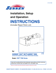
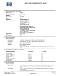
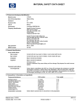
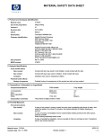
REPAIR PARTS CATALOG FOR
SUNNEN®
HORIZONTAL HONES & ACCESSORIES
MODEL:
CH100,
CH20/CH40, CH455, CH525, & CH850
THIS CATALOG COVERS THE
ABOVE MODEL BEGINNING
WITH SERIAL NO. 3246.
“SUNNEN AND THE SUNNEN LOGO ARE REGISTERED TRADEMARKS OF SUNNEN PRODUCTS COMPANY.”
SUNNEN® PRODUCTS COMPANY
7910 MANCHESTER AVENUE • ST. LOUIS, MO 63143, U.S.A. • PHONE: 314-781-2100
X-CH-1103H
Like any machinery, this equipment may
be dangerous if used improperly. Be sure
to read and follow instructions for
operation of equipment.
INTRODUCTION
Illustrations show all major components in exploded detail. Item numbers on each illustration are keyed to the
corresponding parts list, providing a descriptive identification of each part.
The parts lists include assemblies as well as detail parts. An item listed without a part number can be
obtained as a component of the complete assembly of which it is a part.
Standard hardware items are listed with complete descriptions, such as Item 29 below. These may be
purchased at your local hardware store, but it is important to replace an item with one having the same
dimensions as the original. In some places brand names and part numbers are shown. These may change
depending upon availability.
Sunnen Products Company reserves the right to make changes, without notice, to materials,
specifications, colors, designs and accessories included with units.
HOW TO ORDER
When ordering replacement parts be sure to include the following information to ensure prompt shipment of
correct parts:
1. The part number and description of each part desired, obtained from this parts catalog.
2. The quantity of each part desired.
3. The voltage, frequency and phase, when ordering electrical parts.
4. The model and serial number of the machine, obtained from the name plate, where there is any question
concerning a part.
HOW TO USE THIS PARTS LIST
Step 1. – Locate desired part on illustration. Note item number.
Step 2. – Locate item number in the parts list.
Step 3. – If the item has a part number listed, order by part number and the description. A part number in
light face type indicates that it is a component of the last preceding part number in bold face
type.
Step 4. – If no number is listed, order the part number of the unit of which the desired part is a component.
ORDER ONLY BY PART NUMBER AND DESCRIPTION – NOT by item number.
NOTE: In this manual, parts may be followed by “(For CE Machines)” or “(For Non-CE Machines)” to denote
domestic machines from exported machines. The CE version is constructed to meet the requirements of the
European market, and is available to any customer.
1
Step 1.
4
2
3
15
17
14
Step 2.
Step 3.
Step 4.
ITEM
NO.
ORDER BY
PART
NUMBER
QTY.
1
2
3
4
MVH-4499A
PHSM-405
PHW-354
MVH-4422
1
3
3
1
....Spindle Cap includes
......Screw (M6 x 1 x 16 SHCS)
......Washer (M6)
....Inner Spindle Nose
14
15
16
17
PEM-870A
PEM-871
PEM-872
PHSM-600
1
1
1
1
....Cable Carrier includes
......Cable Carrier Bracket
......Cable Carrier Bracket
....Screw (M3 x 0,5 x 5mm FHCS)
iii
DESCRIPTION
GENERAL INFORMATION
The Sunnen® equipment has been designed and engineered for a wide variety of parts within the capacity and limitation of the equipment. With proper care
and maintenance this equipment will give years of service.
READ THE FOLLOWING INSTRUCTIONS CAREFULLY AND THOROUGHLY BEFORE UNPACKING, INSPECTING, OR INSTALLING THIS EQUIPMENT.
IMPORTANT: Read any supplemental instructions BEFORE installing this equipment. These supplemental instructions give you important information to
assist you with the planning and installation of your Sunnen equipment.
Sunnen Technical Service Department is available to provide telephone assistance for installation, programming, & troubleshooting of your Sunnen
equipment. All support is available during normal business hours, 8:00 AM to 4:30 PM Central Time. Emergency breakdown support is available on a 24
hour / 7 day basis.
Review all literature provided with your Sunnen equipment. This literature provides valuable information for proper installation, operation, and maintenance
of your equipment. Troubleshooting information can also be found within the Instructions. If you cannot find what you need, call for technical support.
Where applicable, programming information for your Sunnen equipment is also included. Most answers can be found in the literature packaged with your
equipment.
Help us help you. When ordering parts, requesting information, or technical assistance about your equipment, please have the following
information available:
• Have ALL MANUALS on hand. The Customer Services Representative or Technician will refer to it.
• Have Model Number and Serial Number printed on your equipment Specification Nameplate.
• Where Applicable: Have Drive model and all nameplate data. Motor type, brand, and all nameplate data.
For Troubleshooting, additional information may be required:
• Power distribution information (type - delta, wye, power factor correction; other major switching devices used, voltage fluctuations)
• Installation Wiring (separation of power & control wire; wire type/class used, distance between drive and motor, grounding).
• Use of any optional devices/equipment between the Drive & motor (output chokes, etc.).
For fast service on your orders call:
Sunnen Automotive Customer Service toll free at: 1-800-772-2878
Sunnen Industrial Customer Service toll free at: 1-800-325-3670
Customers outside the USA, contact your local authorized Sunnen Distributor.
Additional information available at: http://www.sunnen.com or e-mail: [email protected]
NOTE: Sunnen reserves the right to change or revise specifications and product design in connection with any feature of our products contained herein.
Such changes do not entitle the buyer to corresponding changes, improvements, additions, or replacements for equipment, supplies or accessories
previously sold. Information contained herein is considered to be accurate based on available information at the time of printing. Should any discrepancy of
information arise, Sunnen recommends that user verify the discrepancy with Sunnen before proceeding.
ESD PREVENTION REVIEW
Let's review the basics of a sound static control system and its effective implementation. First, in the three step plan:
1.
Always ground yourself when handling sensitive components or assemblies.
2.
Always use a conductive or shielded container during storage or transportation. These materials create a Faraday
cage which will isolate the contents from static charges.
3.
Open ESD safe containers only at a static safe work station.
At the static safe work station, follow these procedures before beginning any work:
A.
Put on your wrist strap or foot grounding devices.
B.
Check all grounding cords to make sure they are properly connected to ground, ensuring the effective dissipation of static charges.
C.
Make sure that your work surface is clean and clear of unnecessary materials, particularly common plastics.
D.
Anti-static bubble wrap has been included for use at the machine when an ESD safe workstation is not available.
You are now properly grounded and ready to begin work. Following these few simple rules and using a little common sense will go a long
way toward helping you and your company in the battle against the hazards of static electricity. When you are working with ESD sensitive devices, make sure you:
GROUND
ISOLATE
NEUTRALIZE
iv
SUNNEN® LIMITED PRODUCT WARRANTY
Sunnen® Products Company and its subsidiaries (SPC) warrant that all new SPC honing machines, gaging equipment, tooling, and related equipment will
be free of defects in material and/or workmanship for a period of one year from the date of original shipment from SPC.
Upon prompt notification of a defect during the one-year period, SPC will repair, replace, or refund the purchase price, with respect to parts that prove to be
defective (as defined above). Any equipment or tooling which is found to be defective from improper use will be returned at the customer's cost or repaired
(if possible) at customer's request. Customer shall be charged current rates for all such repair.
Prior to returning any SPC product, an authorization (RMA#) and shipping instructions must be obtained from the Customer Service Department or items
sent to SPC will be returned to the customer.
Warranty Limitations and Exclusions This Warranty does not apply to the following:
• Normal maintenance items subject to wear and tear: (belts, fuses, filters, etc).
• Damages resulting from but not limited to:
› Shipment to the customer (for items delivered to customer or customer's agent F.O.B., Shipping Point)
› Incorrect installation including improper lifting, dropping and/or placement
› Incorrect electric power (beyond +/- 10% of rated voltage) including intermittent or random voltage spikes or drops
› Incorrect air supply volume and/or pressure and/or contaminated air supply
› Electromagnetic or radio frequency interference from surrounding equipment (EMI, RFI)
› Storm, lightning, flood or fire damage
› Failure to perform regular maintenance as outlined in SPC manuals
› Improper machine setup or operation causing a crash to occur
› Misapplication of the equipment
› Use of non-SPC machines, tooling, abrasive, fixturing, coolant, repair parts, or filtration
› Incorrect software installation and/or misuse
› Non-authorized customer installed electronics and/or software
› Customer modifications to SPC software
THE LIMITED WARRANTY DESCRIBED HEREIN IS EXPRESSLY IN LIEU OF ALL ANY OTHER WARRANTIES. SPC MAKES NO REPRESENTATION OR WARRANTY OF ANY
OTHER KIND, EXPRESS OR IMPLIED, WHETHER AS TO MERCHANTABILITY, FITNESS FOR A PARTICULAR PURPOSE OR ANY OTHER MATTER. SPC IS NOT
RESPONSIBLE FOR THE IMPROPER USE OF ANY OF ITS PRODUCTS. SPC SHALL NOT BE LIABLE FOR DIRECT, INDIRECT, INCIDENTAL, OR CONSEQUENTIAL
DAMAGES INCLUDING BUT NOT LIMITED TO: LOSS OF USE, REVENUE, OR PROFIT. SPC ASSUMES NO LIABILITY FOR PURCHASED ITEMS PRODUCED BY OTHER
MANUFACTURERS WHO EXTEND SEPARATE WARRANTIES. REGARDLESS OF ANY RIGHTS AFFORDED BY LAW TO BUYER, SPC's LIABILITY, IF ANY, FOR ANY AND
ALL CLAIMS FOR LOSS OR DAMAGES WITH RESPECT TO THE PRODUCTS, AND BUYER'S SOLE AND EXCLUSIVE REMEDY THEREFORE, SHALL IN ALL EVENTS BE
LIMITED IN AMOUNT TO THE PURCHASE PRICE OF THAT PORTION OF THE PRODUCTS WITH RESPECT TO WHICH A VALID CLAIM IS MADE.
Shipping Damages
Except in the case of F.O.B., Buyer's destination shipments, SPC will not be liable for any settlement claims for obvious and/or concealed shipping damages.
The customer bears the responsibility to unpack all shipments immediately and inspect for damage. When obvious and/or concealed damage is found, the
customer must immediately notify the carrier's agent to make an inspection and file a claim. The customer should retain the shipping container and packing
material.
SUNNEN® SOFTWARE LICENSE AGREEMENT
This document is a Legal Agreement between you, as user and licensee (Licensee), and Sunnen® Products Company (SPC) with respect to preprogrammed
software (Software) provided by SPC for use on SPC Equipment. By using the Software, you, as Licensee, agree to become bound by the terms of this
Agreement.
In consideration of payment of the license fee (License Fee) which is part of the price evidenced by your receipt (Receipt), SPC grants to you as Licensee
a non-exclusive right, without right to sub-license, to use the particular copy of the SPC Software licensed hereunder only on the particular equipment sold with
the Software. SPC reserves all rights including rights not otherwise expressly granted, and retain title and ownership to the Software including all subsequent
copies or updates in any media. The Software and all accompanying written materials are covered by copyrights owned by SPC. If supplied on removable
media (floppy disk), you, as Licensee, may copy the Software only for back up purposes; or you may request that SPC copy the Software for you for the
same purposes. All other copying of the Software or of the accompanying written materials is expressly forbidden and is in violation of the Agreement.
The Software and accompanying written materials (including the user's manual, if any) are provided in an "as is" condition without warranty of any kind
including the implied warranties of merchantability and fitness for a particular purpose, even if SPC has been advised of this purpose. SPC specifically does
not warrant that it will be liable as a result of the operation of the Software for any direct, indirect, consequential or accidental damages arising out of the
use of or inability to use such product even if SPC has been advised of the possibility of such use. It is recognized that some states do not allow the exclusion or limitation of liability for consequential or accidental damages and to the extent this is true, the above limitations may not apply.
Any alteration or reverse engineering of the software is expressly forbidden and is in violation of this agreement.
SPC reserves the right to update the software covered by this agreement at any time without prior notice and any such updates are covered by this
agreement.
v
SAFETY INSTRUCTIONS
READ FIRST
This machine, like any equipment, may be dangerous if used improperly. Please
read all warnings and instructions before attempting to use this machine.
Always disconnect power at main enclosure before servicing machine.1
Always wear eye protection when operating this machine.
NEVER open or remove any machine cover or protective guard with power "ON."
Always disconnect power at main enclosure before servicing this equipment.1
DO NOT attempt any repair or maintenance procedure beyond those described in
this book. Contact your Sunnen® Field Service Engineer or Technical Services
Representative for repairs not covered in these instructions.
Due to the wide variety of machine configurations, all possibilities cannot be
described in these instructions. Instructions for safe use and maintenance of
optional equipment ordered through Sunnen, will be provided through separate
documentation and/or training provided by your Sunnen Field Service Engineer or
Technical Services Representative.
DO NOT attempt to defeat any safety device on this machine or on any of the
optional equipment.
If specially built automation components are added to this system, be sure that
safety is not compromised. If necessary, obtain special enlarged work area safety
system from Sunnen Products Co.
Indicates CE version ONLY.
1
DO NOT touch electrical components until main input power has been turned off and CHARGE
lamps are extinguished. WARNING: The capacitors are still charged and can be quite dangerous.
vi
CONTENTS
PAGE
Introduction ..........................................................................................................
How To Order .......................................................................................................
How To Use This Parts List .................................................................................
General Information .............................................................................................
ESD Prevention Review .......................................................................................
Limited Product Warranty ....................................................................................
Sunnen Software License Agreement ..................................................................
General Safety Instructions ..................................................................................
Contents ...............................................................................................................
iii
iii
iii
iv
iv
v
v
vi
1
SECTION I BASIC MACHINE
1-A CH100 Horizontal Hone........................................................................................ 2
1-B Hone Driver........................................................................................................... 7
SECTION II CH20A/K & CH40A/K HORIZONTAL HONE DRIVER
2-A CH20/40 Horizontal Hone Driver .......................................................................... 8
SECTION III CH455 CRADLE & CH525 OIL CONTROL
3-A CH455/525 Cradle & Oil Control Assemblies....................................................... 10
SECTION IV CH850A/K/KA SWITCH BOX ASSEMBLY
4-A CH850 Switch Box Assembly ............................................................................... 12
“SUNNEN AND THE SUNNEN LOGO ARE REGISTERED TRADEMARKS OF SUNNEN PRODUCTS COMPANY.”
© Copyright 2006 by Sunnen® Products Company • Printed in U.S.A.
Page 1
SECTION I - BASIC MACHINE
FIGURE 1-A – CH100 HORIZONTAL HONE (1 OF 2)
Page 2
SECTION I
BASIC MACHINE
PARTS LIST COVERING FIGURE “1-A” (1 of 2)
ITEM
NO.
1
N/S
N/S
1
N/S
N/S
3
N/S
4
5
N/S
N/S
N/S
6
7
N/S
8
N/S
N/S
10
11
12
13
14
15
N/S
16
17
18
19
N/S
20
N/S
N/S
21
N/S
N/S
22
23
24
25
N/S
N/S
26
ORDER BY
PART
NUMBER
CH157A
----CH182A
----CH160A
CH173A
CH140A
CH154A
------CH190A
CH187A
--CH352A
HS-205A
HS-210A
CHV-199A
CH568A
CH564A
CH494A
CH497A
CH585A
--CH496A
CH490A
CH636A
PHS523A
PHN109
CH498A
PHS528
LBN407
CH480A
PHS549
KN370
CH475A
CH465A
CH469A
CH470A
KN538
LBN-462A
CH550A
N/S indicates Not Shown
QTY.
1
1
1
1
1
1
1
1
1
1
2
2
2
1
1
1
1
1
1
1
1
1
2
2
1
1
2
2
1
1
1
2
4
4
2
2
2
2
1
1
1
1
1
1
DESCRIPTION
....Drill Support with
......Shaft
......Taper Pin
....Stop Collar with
......Set Screw (1/4-20x3/8 Soc. Cup Pt.)
......Insert
....Lock Arm Assembly with
......Plunger
....Carriage Assembly
....Lock Plate with
......Screws (3/8-16x2 Hex Hd. Cap)
......Lock Washers
......Nuts (3/8-16 Hex)
....Stop Plate Assembly, Right with
......Bumper Set (Pkg. of 2) with
........Screw (6-32x7/8 But. Hd. Cap)
....Hose
....Pump (60 Hz)
....Pump (220 V, 50 Hz / 230 V, 60 Hz)
....Elevating Handle
....Pan
....Foam Pad
....Screw (Pkg. of 1)
....Clamp Nut (Pkg. of 1)
....Clamp Bar Set with
......Outside Clamp Bar
....Jam Nut (Pkg. of 1)
....Clamp Assembly (Pkg. of 1)
....Wrench
....Leveling Screw (3/4-16x2-1/4 Hex Hd. Cap) with
......Nut (3/4-16 Hex Jam)
....Cross Bar (Pkg. of 1) with
......Screws (3/8-16x2-1/2 Hex Hd. Cap)
......Washers (7/8 O.D. x 3/8 I.D. x .065 Thick)
....Nest Pivot Assembly (Pkg of 1) with
......Screws (1/2-13x1-1/2 Hex Hd. Cap)
......Washers (7/8 O.D. x 33/64 I.D. x .065 Thick)
....Cradle Nest (Pkg. of 1)
....Elevating Nut Assembly
....Clamp Plate
....Tee Handle Assembly with
......Washer (1” O.D. x 17/32 I.D. x 1/8 Thick)
....Mandrel Wrench (1/4 Hex)
....Splash Guard
(Parts continued on next page)
Page 3
SECTION I
BASIC MACHINE
FIGURE 1-A – CH100 HORIZONTAL HONE (2 OF 2)
Page 4
SECTION I
BASIC MACHINE
PARTS LIST COVERING FIGURE “1-A” (2 of 2)
ITEM
NO.
1
1
N/S
N/S
N/S
N/S
N/S
N/S
2
3
4
N/S
-5
N/S
6
7
8
9
10
11
12
13
N/S
N/S
14
15
N/S
16
N/S
17
18
N/S
N/S
N/S
19
N/S
N/S
20
N/S
N/S
N/S
21
22
N/S
23
N/S
N/S
24
ORDER BY
PART
NUMBER
CH705A
CH805A
CH714A
CH814A
CH715A
CH815A
CH726A
CH760A
CH85A
CH575A
CH577A
--CH505A
CH540A
POR105A
PPP483A
PPP147A
CH520A
PHR324A
CH510A
CH514A
CH599A
CH541A
PHS559
CH542
PPP132A
CH462A
CH458A
CH464A
KN386
PBR42A
CH435A
PRB41A
PHS654A
CH440A
CK3006A
CK3007
MAN1028
CH425A
CH429A
----CH468A
CK1128A
PHS104
CV6023
CV6022
CV6040
CK1010A
N/S indicates Not Shown
QTY.
1
1
1
1
1
1
2
1
1
2
2
3
1
1
2
1
1
1
1
1
10
1
1
3
1
1
1
2
1
2
2
2
2
4
2
1
1
2
2
1
2
2
1
1
1
1
1
1
1
DESCRIPTION
....Drill Assembly (115 V, 60 Hz)
....Drill Assembly (220 V, 50 Hz / 230 V, 60 Hz)
....Armature (For CH705A)
....Armature (For CH805A)
....Field (For CH705A)
....Field (For CH805A)
....Brush Set
....Non-Reversing Switch
....Quick Coupler Assembly
....Protective Cover Assembly (Pkg. of 1) with
......Wood Block (Pkg of 1) with
........Screws (8 x 5/8 Flat Hd. Self Tapping)
....Oilspout & Valve Assembly Includes
......Valve Body Assembly Includes
........“O” Rings (E.F. Houghton #ARP-568-218) (Pkg. of 2)
........Mini Ball Valve with
..........Nipple
........Shell Assembly
........Retaining Ring (Truarc #5100-150PP)
......Oilspout Assembly Includes
........Spring Clips (Pkg. of 2)
....Foam Pad
....Clamp Plate with
......Screws (5/16-18 x 1-3/4 Soc. Hd. Cap)
......Spacer
....Adapter
....Chain includes (Connecting Pin & Cotter Pin)
....Chain includes (Connecting Pin & Cotter Pin) (Pkg. of 1)
....Idler Adjustment Screw (Pkg. of 1) with
......Nuts (1/2 x 13 Hex)
....Thrust Bearing (Pkg. of 1)
....Bearing Support Block (Pkg. of 1) with
......Bushing (Torrington #10SBB16) (Pkg. of 1)
......Screw
....Idler Arm Assembly (Pkg. of 1)
....Gage Hanger with
......Clamp
......Screws (1/4-20 x 3/4 Hex Hd. Cap)
....Elevating Screw (Pkg. of 1)
....Sprocket with
......Keys (Woodruff #61)
......Set Screws (1/4-20 x 1/4 Soc. Plain Cup Pt.)
....Elevating Nut
....Stop Collar with
......Set Screw (3/8-16 x 1/2 Soc. Half Dog Pt.)
....Door-Lower
....Door-Center
....Door-Upper
....Non-Splash Screen
(Parts continued on next page)
Page 5
SECTION I
BASIC MACHINE
PARTS LIST COVERING FIGURE “1-A” (cont’d)
ITEM
NO.
25
26
N/S
N/S
N/S
27
28
N/S
N/S
N/S
29
N/S
N/S
30
31
32
N/S
33
34
N/S
N/S
N/S
35
35
ORDER BY
PART
NUMBER
CH595A
CH560A
PHS-653
LBN431
PHW118
CH564A
CH216A
--CH146A
CH150A
CH208A
PES136A
PHS666
PES214A
CH185A
CH187A
--CH194A
CH-129
PEF141
PEF135
PEF175
CH-850A
CH-850K
N/S indicates Not Shown
Page 6
QTY.
1
1
2
2
2
1
1
4
1
1
1
1
2
1
1
1
1
1
2
1
1
1
1
1
DESCRIPTION
....Non-Splash Screen includes Support
....Drip Tray Assembly with
......Screws (1/4-20 x 3/4 But. Hd. Cap)
......Nuts (1/4-20 Hex)
......Washers (1/4 Lock)
......Foam Pad
....Mounting Angle Cover with
......Screws (10-32 x 1/4 But. Hd. Cap)
....Torque Arm
....Tire Assembly
....Cover Plate with
......Pilot Light
......Screw
....Motor Starting Switch
....Stop Plate Assembly - Left with
......Bumper Set (Pkg. of 2) with
........Screw (6-31 x 7/8 But. Hd. Cap)
....Shaft
....Shaft Support
....Fuse (220 V, 50 Hz / 230 V, 60 Hz)
....Fuse (115 V, 60 Hz)
....Fuse (115 V, 60 Hz)
....Switch Box Assembly (220V, 50Hz) (see Fig. 4-A)
....Switch Box Assembly (115V, 60Hz) (see Fig. 4-A)
SECTION I
BASIC MACHINE
FIGURE 1-B – HONE DRIVER
PARTS LIST COVERING FIGURE “1-B”
ITEM
NO.
1
-N/S
2
3
4
5
6
7
8
N/S
---
9
N/S
N/S
10
N/S
N/S
N/S
N/S
11
N/S
N/S
N/S
12
N/S
N/S
N/S
ORDER BY
PART
NUMBER
CH85A
CH75A
CH88A
AN97
AN675A
AN640A
AN619A
CH77A
GGN101A
CH78A
CH79A
--CH80A
GGN130A
GGN111A
--LBN346A
CH76A
----GGN118C
GGN112A
--GGN101A
CH79A
GGN106A
--LBN462A
AN840
QTY.
Ref.
Ref.
1
1
1
1
1
1
2
2
2
Ref.
1
1
1
1
1
1
3
1
1
2
2
2
1
1
1
1
DESCRIPTION
....Quick Coupler Assembly
....Hone Driver Complete consists of
......Spacer
......Yoke Adapter
......Universal Joint
......Extension Coupler
......Universal Yoke
......Universal Ring with
........Universal Screws (Must be assembled with Loctite)
........Screws
......Plugs (Fits under GGN-101A, item 7, applies tension to
Feed Dial - Set Screws must be assembled with Loctite)
......Body Tension & Feed Assembly consists of
........Body & Tension Dial Assembly
........Feed Screw
........Washer (3/4 O.D. x 3/8 I.D. x 3/64 Nylon)
........Set Screw (1/2-13 x 7/16 Soc. Flat Pt.)
........Mandrel Drive Plate
........Set Screw (6-32 x 5/16 Soc. Flat Pt. with Nylok)
........Set Screws (1/4-20 x 7/16 Soc. Full Dog Pt.)
........Feed Link
........Handle
........Screws (10-32 x 1/2 Flat Hd. Soc. Cap)
........Universal Screws (Also supplied with item 6)
........Plugs (Also supplied with item 6)
........Feed Knob
........Set Screw (10-32 x 5/16 Soc. Cap Pt.)
....Mandrel Wrench (1/4 Hex)
....Heavy Duty Extension (6”)
N/S indicates Not Shown
Page 7
SECTION II – HORIZONTAL HONE DRIVER
FIGURE 2-A – CH20A/K & CH40A/K HORIZONTAL HONE DRIVER
Page 8
SECTION II
HORIZONTAL HONE DRIVER
PARTS LIST COVERING FIGURE “2-A”
ITEM
NO.
1
N/S
N/S
N/S
N/S
1
N/S
N/S
N/S
N/S
2
3
-4
5
6
N/S
7
7
8
9
10
11
12
13
14
ORDER BY
PART
NUMBER
CH705A
CH714A
CH715A
CH726A
CH760A
CH805A
CH814A
CH815A
CH726A
CH760A
CH85A
LBN462A
--CH194A
CH185A
CH187A
CH190A
PEM385A
CH193A
CH216A*
CH182A
CH157A
CH560A*
CH564A
CH568A*
CH550A
QTY.
1
1
1
2
1
1
1
1
2
1
1
1
Ref.
1
1
1
1
2
2
1
1
1
1
1
1
1
DESCRIPTION
....Drill Assembly (115 V, 60 Hz)
......Armature (For CH705A)
......Field (For CH705A)
......Brush Set
......Non-Reversing Switch
......Drill Assembly (220 V, 50 Hz)
......Armature (For CH805A)
......Field (For CH805A)
......Brush Set
......Non-Reversing Switch
....Hone Driver (see Figure “B”)
....Mandrel Wrench (1/4 Hex)
....Horizontal Hone Driver includes
......Shaft
......Stop Plate Assembly - Left with
........Bumper Set (Pkg. of 2) with Screw (6-32 x 7/8 But. Hd. Cap)
......Stop Plate Assembly - Right
......Cover Plate (For 60 Hz Machine) (Pkg. of 1)
......Cover Plate (For 50 Hz Machine) (Pkg. of 1)
......Mounting Angle Cover with Screws
......Stop Collar with Set Screw & Insert
......Drill Support with Shaft & Taper Pin
......Drip Tray Assembly with Attaching Hardware &
........Tray Pad
......Pan with item 12
....Splash Guard, Portable
N/S indicates Not Shown
NOTE: CH525 & CH850 must be ordered separately (not included with CH-20 or CH-40 Kits).
Page 9
SECTION III – CRADLE & OIL CONTROL
FIGURE 3-A – CH455 CRADLE & CH525 OIL CONTROL
Page 10
SECTION III
CRADLE & OIL CONTROL
PARTS LIST COVERING FIGURE “3-A”
ITEM
NO.
1
2
3
4
5
6
7
8
N/S
N/S
21
N/S
N/S
--
9
10
11
12
13
N/S
N/S
14
15
16
N/S
N/S
17
18
N/S
N/S
19
20
N/S
ORDER BY
PART
NUMBER
CH525
CH535A
CH514A
CH530A
PHR-324A
POR-105A
CH520A
CH515A
CH541C
CH542
PHS630
CK1309C
CK1313
PHN125
CH455
CH494A
CH497A
CH496A
CH490A
CH501A
KN422
--CH502A
CH493A
CH499A
PHS528
--CH636A
CH480A
PHS-549
KN370
CH475A
CH585A
---
DESCRIPTION
QTY.
Ref.
1
8
1
1
2
1
1
1
1
3
1
1
1
Ref.
2
2
2
2
2
4
4
2
2
2
4
8
1
2
2
2
2
1
1
....Oil Control consists of
......Oilspout Assembly includes
........Spring Clip (Pkg. of 2)
......Valve Body Assembly includes
........Retaining Ring (Truarc #5100-150-PP)
........“O” Ring (E.F. Houghton #ARP-568-218)
........Shell Assembly
......Oiler Bracket Assembly
......Clamp Plate with
........Spacer
......Screws (5/16-18 x 1-1/4 Soc. Hd. Cap)
......Hose
......Hose Clamp
......Locknut
......Cradle consists of
......Screw (Pkg. of 1)
......Clamp Nut (Pkg. of 1)
......Jam Nut (Pkg. of 1)
......Clamp Assembly (Pkg. of 1)
......Cross Angle (Pkg. of 1) with
........Screws (3/8-16 x 1” Hex Hd. Cap)
........Washers (3/8 Lock)
......Riser Block Assembly (Pkg. of 1)
......Clamp Plates (For 6 cylinder Straight Engine Blocks) (Pkg. of 2)
......Cross Bar (Pkg. of 1) with
........Screws (3/8-16 x 2-1/2 Hex Hd. Cap)
........Washers (7/8 O.D. x 3/8 I.D. .065 Thick)
......Special Wrench
......Nest Pivot Assembly (Pkg. of 1) with
........Screws (1/2-13 x 1-1/2 Hex Hd. Cap)
........Washers (7/8 O.D. x 33/64 I.D..x .065 Thick)
......Cradle Neck (Pkg. of 1)
......Clamp Bar Set with
........Outside Clamp Bar
N/S indicates Not Shown
NOTE: CH525 must be ordered separately (not included with CH-20 or CH-40 Kits).
Page 11
SECTION IV – SWITCH BOX ASSEMBLY
CH850A
CH850K
FIGURE 4-A – CH850A/K/KA SWITCH BOX ASSEMBLY
Page 12
SECTION IV
SWITCH BOX ASSEMBLY
PARTS LIST COVERING FIGURE “4-A”
ITEM
NO.
1
2
3
4
5
6
7
8
9
10
11
12
13
14
15
16
17
18
19
20
1
2
3
4
5
6
7
8
9
10
11
12
13
14
15
16
17
18
19
20
21
22
23
ORDER BY
PART
NUMBER
CH850A
PEM768
PEM767
PNP318
PES297
DRB0125
PHSM438
CH853
PEM755
PEF141
DRB0100
PEM473
PEM154
PEM252
PEC103
PHN125
MSA63
LBA451
PEM823
PET545
PEM729
CH850K
PEM768
PEM728
PEM767
PET551
PNP318
PES297
DRB0125
PHSM438
CH853
PEM755
PEF175
DRB0100
PEM473
PEF135
PEM154
PEM252
PEC103
PHN125
MSA63
LBA451
PEM823
PET545
PEM729
DESCRIPTION
QTY.
Ref.
1
1
1
1
1
4
1
2
2
1
3
1
1
1
1
1
1
1
1
2
Ref.
1
2
1
1
1
1
1
4
1
2
1
1
3
1
1
1
1
1
1
1
1
1
2
....Switch Box Assembly consists of
......Enclosure
......Panel
......Electrical Decal
......Non-Fused Disconnect Switch
......Din Rail (125mm)
......Screw (M5 X 0.8 X 12mm PPHTCS)
......Disconnect Rod (4.125)
......Ultrasafe Class CC Fuseholder
......Fuse (CCMR-10 Class CC)
......Din Rail (100mm)
......End Stop
......Wire & Cable Marking Label; 500 Labels Per Roll
......Sealing 'O' Ring With Retainer
......Conduit Connector With Locknut
......Locknut (1/2" Npt)
......Nut, Hex (#10-32)
......Lockwasher, External Tooth (#10)
......Knockout Plug
......Protective Earth Ground
......Marking Tag
....Switch Box Assembly consists of
......Enclosure
......Marking Tag
......Panel
......Terminal Block - Neutral
......Electrical Decal
......Non-Fused Disconnect Switch
......Din Rail (125mm)
......Screw (M5 X 0.8 X 12mm PPHTCS)
......Disconnect Rod
......Ultrasafe Class CC Fuseholder
......Fuse
......Din Rail (100mm)
......End Stop
......Fuse
......Wire & Cable Marking Label; 500 Labels Per Roll
......Sealing 'O' Ring With Retainer
......Conduit Connector With Locknut
......Locknut (1/2" Npt)
......Nut, Hex (#10-32)
......Lockwasher, External Tooth (#10)
......Knockout Plug
......Protective Earth Ground
......Marking Tag
N/S indicates Not Shown
NOTE: CH850 must be ordered separately (not included with CH-20 or CH-40 Kits).
Page 13
NOTES
Page 14
NOTES
Page 15
NOTES
Page 16
WARNING
An Arc Flash Hazard Exists. Follow safe work
practices and wear appropriate Personal
Protective Equipment. Follow proper
lockout/tagout procedures. Failure to comply
can result in death or injury.
Like any machinery, this equipment may
be dangerous if used improperly. Be
sure to read and follow instructions for
operation of equipment.
FRACTION / DECIMAL / MILLIMETER EQUIVALENTS CHART
INCH
FRACTION
DECIMAL
MILLIMETER
INCH
FRACTION
DECIMAL
MILLIMETER
INCH
FRACTION
DECIMAL
MILLIMETER
....
.003937
0,1000
9/32
.281250
7,1438
21/32
.656250
16,6688
....
.007874
0,2000
19/64
.296875
7,5406
....
.669291
17,0000
....
.011811
0,3000
5/16
.312500
7,9375
43/64
.671875
17,0656
1/64
.015625
0,3969
....
.314961
8,0000
11/16
.687500
17,4625
....
.015748
0,4000
21/64
.328125
8,3344
45/64
.703125
17,8594
....
.019685
0,5000
11/32
.343750
8,7313
....
.708661
18,0000
....
.023622
0,6000
....
.354331
9,0000
23/32
.718750
18,2563
....
.027559
0,7000
23/64
.359375
9,1281
47/64
.734375
18,6531
1/32
.031250
0,7938
3/8
.375000
9,5250
....
.748031
19,0000
....
.031496
0,8000
25/64
.390625
9,9219
3/4
.750000
19,0500
....
.035433
0,9000
....
.393701
10,0000
49/64
.765625
19,4469
....
.039370
1,0000
13/32
.406250
10,3188
25/32
.781250
19,8438
3/64
.046875
1,1906
27/64
.421875
10,7156
....
.787402
20,0000
1/16
.062500
1,5875
....
.433071
11,0000
51/64
.796875
20,2406
5/64
.078125
1,9844
7/16
.437500
11,1125
13/16
.812500
20,6375
....
.078740
2,0000
29/64
.453125
11,5094
....
.826772
21,0000
3/32
.093750
2,3813
15/32
.468750
11,9063
53/64
.828125
21,0344
7/64
.109375
2,7781
....
.472441
12,0000
27/32
.843750
21,4313
....
.118110
3,0000
31/64
.484375
12,3031
55/64
.859375
21,8281
1/8
.125000
3,1750
1/2
.500000
12,7000
....
.866142
22,0000
9/64
.140625
3,5719
....
.511811
13,0000
7/8
.875000
22,2250
5/32
.156250
3,9688
33/64
.515625
13,0969
57/64
.890625
22,6219
....
.157480
4,0000
17/32
.531250
13,4938
....
.905512
23,0000
11/64
.171875
4,3656
35/64
.546875
13,8906
29/32
.906250
23,0188
3/16
.187500
4,7625
....
.551181
14,0000
59/64
.921875
23,4156
....
.196850
5,0000
9/16
.562500
14,2875
15/16
.937500
23,8125
13/64
.203125
5,1594
37/64
.578125
14,6844
....
.944882
24,0000
7/32
.218750
5,5563
....
.590551
15,0000
61/64
.953125
24,2094
15/64
.234375
5,9531
19/32
.593750
15,0813
31/32
.968750
24,6063
....
.236220
6,0000
39/64
.609375
15,4781
....
.984252
25,0000
1/4
.250000
6,3500
5/8
.625000
15,8750
63/64
.984375
25,0031
17/64
.265625
6,7469
....
.629921
16,0000
1
1.000000
25,4000
....
.275591
7,0000
41/64
.640625
16,2719
1-1/16
1.062500
26,9880
FORMULAS:
MULTIPLY
INCHES (in)
FEET (ft)
x
x
BY
25.4
0.3048
=
=
TO GET
MILLIMETERS (mm)
METERS (m)
MULTIPLY
MILLIMETERS (mm)
METERS (m)
“SUNNEN® AND THE SUNNEN LOGO ARE REGISTERED TRADEMARKS OF SUNNEN PRODUCTS COMPANY.”
Sunnen® reserves the right to change or
revise specifications and product design
in connection with any feature of our
products contained herein. Such changes
do not entitle the buyer to corresponding
changes, improvements, additions, or
replacements for equipment, supplies or
accessories previously sold. Information
contained herein is considered to be
accurate based on available information
at the time of printing. Should any
discrepancy of information arise, Sunnen
recommends that user verify discrepancy
with Sunnen before proceeding.
PRINTED IN U.S.A.
1209
SUNNEN PRODUCTS COMPANY
7910 Manchester Road, St. Louis, MO 63143 U.S.A.
Phone: 314-781-2100
Fax: 314-781-2268
U.S.A. Toll-Free Sales and Service:1-800-325-3670
International Division Fax: 314-781-6128
http://www.sunnen.com
e-mail: [email protected]
x
x
BY
0.03937
3.281
=
=
TO GET
INCHES (in)
FEET (ft)
SWITZERLAND – SUNNEN AG
Phone: ++ 41 71 649 33 33
Fax: ++ 41 71 649 34 34
www.sunnen.ch
e-mail: [email protected]
ITALY - SUNNEN ITALIA S.R.L.
Phone: 39 02 383 417 1
Fax: 39 02 383 417 50
www.sunnenitalia.com
e-mail: [email protected]
FRANCE – SUNNEN SAS
Phone: +33 01 69 30 0000
Fax: +33 01 69 30 1111
www.sunnen.fr
e-mail: [email protected]
BELGIUM – SUNNEN BENELUX BVBA
Phone: +32 38 80 28 00
Fax: +32 38 44 39 01
www.sunnen.be
e-mail: [email protected]
UK – SUNNEN PRODUCTS LTD.
Phone: ++ 44 1442 39 39 39
Fax: ++ 44 1442 39 12 12
www.sunnen.co.uk
e-mail: [email protected]
POLAND – SUNNEN POLSKA SP. Z O.O.
Phone: +48 22 814 34 29
Fax: +48 22 814 34 28
www.sunnen.pl
e-mail: [email protected]
RUSSIA – SUNNEN RUS
Phone: +7 495 258 43 43
Fax: +7 495 258 91 75
www.sunnen.ru
e-mail: [email protected]
CZECH REPUBLIC – SUNNEN S.R.O.
Phone: +420 383 376 317
Fax: +420 383 376 316
www.sunnen.cz
e-mail: [email protected]
CHINA – SHANGHAI SUNNEN MECHANICAL CO., LTD.
Phone: 86 21 5813 3322
Fax: 86 21 5813 2299
www.sunnensh.com
e-mail: [email protected]
©COPYRIGHT SUNNEN® PRODUCTS COMPANY 2012, ALL RIGHTS RESERVED