1
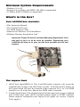
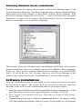
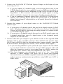
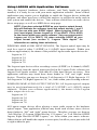
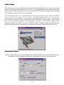
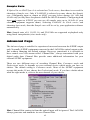
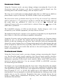
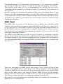
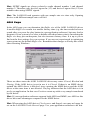
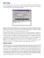
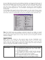
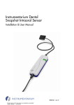
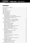
LAGOON
LAGOON
TM
MANUAL
™
Table of Contents
Introduction . . . . . . . . . . . . . . . . . . . . . . . . . . . . . . . . . . . . . . . . . . . . . . . .3
Features . . . . . . . . . . . . . . . . . . . . . . . . . . . . . . . . . . . . . . . . . . . . . . . . . . .3
Included Drivers: . . . . . . . . . . . . . . . . . . . . . . . . . . . . . . . . . . . . . . . . .3
Minimum System Requirements . . . . . . . . . . . . . . . . . . . . . . . . . . . . . . . . .4
What’s in the Box? . . . . . . . . . . . . . . . . . . . . . . . . . . . . . . . . . . . . . . . . . . .4
The Lagoon Card . . . . . . . . . . . . . . . . . . . . . . . . . . . . . . . . . . . . . . . . . . . .4
Installation . . . . . . . . . . . . . . . . . . . . . . . . . . . . . . . . . . . . . . . . . . . . . . . . .5
Checking IRQs . . . . . . . . . . . . . . . . . . . . . . . . . . . . . . . . . . . . . . . . . . . . . .5
Hardware Installation . . . . . . . . . . . . . . . . . . . . . . . . . . . . . . . . . . . . . . . . .6
Windows Driver and Software Installation . . . . . . . . . . . . . . . . . . . . . . . . .7
Windows 98 Installation . . . . . . . . . . . . . . . . . . . . . . . . . . . . . . . . . . .7
Windows 95 Installation . . . . . . . . . . . . . . . . . . . . . . . . . . . . . . . . . . .7
Verifying Windows Driver Installation . . . . . . . . . . . . . . . . . . . . . . . . .8
Software Installation . . . . . . . . . . . . . . . . . . . . . . . . . . . . . . . . . . . . . .8
Verifying Lagoon Tools Applet Software Installation . . . . . . . . . . . . . .9
Setting Up Your Digital Studio . . . . . . . . . . . . . . . . . . . . . . . . . . . . . . . . . .9
Using LAGOON with Application Software . . . . . . . . . . . . . . . . . . . . . . .11
The LAGOON Tools Applet . . . . . . . . . . . . . . . . . . . . . . . . . . . . . . . . . . .12
Info Page . . . . . . . . . . . . . . . . . . . . . . . . . . . . . . . . . . . . . . . . . . . . . . . . . .13
General Page . . . . . . . . . . . . . . . . . . . . . . . . . . . . . . . . . . . . . . . . . . . . . . .13
Mode . . . . . . . . . . . . . . . . . . . . . . . . . . . . . . . . . . . . . . . . . . . . . . . . .14
Clock Source . . . . . . . . . . . . . . . . . . . . . . . . . . . . . . . . . . . . . . . . . . .14
Sample Rate . . . . . . . . . . . . . . . . . . . . . . . . . . . . . . . . . . . . . . . . . . . .15
Advanced Page . . . . . . . . . . . . . . . . . . . . . . . . . . . . . . . . . . . . . . . . . . . . .15
Consumer Mode . . . . . . . . . . . . . . . . . . . . . . . . . . . . . . . . . . . . . . . .16
Professional Mode . . . . . . . . . . . . . . . . . . . . . . . . . . . . . . . . . . . . . . .16
MME Page . . . . . . . . . . . . . . . . . . . . . . . . . . . . . . . . . . . . . . . . . . . . . . . .17
ASIO Page . . . . . . . . . . . . . . . . . . . . . . . . . . . . . . . . . . . . . . . . . . . . . . . .18
MIDI Page . . . . . . . . . . . . . . . . . . . . . . . . . . . . . . . . . . . . . . . . . . . . . . . .19
Status Page . . . . . . . . . . . . . . . . . . . . . . . . . . . . . . . . . . . . . . . . . . . . . . . .19
Input Errors . . . . . . . . . . . . . . . . . . . . . . . . . . . . . . . . . . . . . . . . . . . .20
Output Error . . . . . . . . . . . . . . . . . . . . . . . . . . . . . . . . . . . . . . . . . . .22
MIDI Errors . . . . . . . . . . . . . . . . . . . . . . . . . . . . . . . . . . . . . . . . . . . .23
Sample Rates and Performance . . . . . . . . . . . . . . . . . . . . . . . . . . . . .24
Troubleshooting . . . . . . . . . . . . . . . . . . . . . . . . . . . . . . . . . . . . . . . . . . . .25
Lifetime Limited Warranty . . . . . . . . . . . . . . . . . . . . . . . . . . . . . . . . . . . .26
FCC Class B / European CE Compliance
WARNING: This equipment has been tested and found to comply with the limits for
a CLASS B digital device, pursuant to Part 15 of the FCC Rules. These limits are
designed to provide reasonable protection against harmful interference in a
residential installation. This equipment generates, uses and can radiate radio
frequency energy and, if not installed and used in accordance with the instructions
contained in this manual, may cause harmful interference to radio and television
communications. However, there is no guarantee that interference will not occur in
a particular installation.
If this equipment does cause harmful interference to radio or television reception,
which can be determined by turning the equipment off and on, the user is encouraged
to try to correct the interference by one or more of the following measures:
1) reorient or relocate the receiving antenna; 2) increase the separation between the
equipment and the receiver; 3) connect the equipment into an outlet on a circuit
different from that of the receiver; 4) consult the dealer or an experienced audio
television technician.
NOTE: Connecting this device to peripheral devices that do not comply with
CLASS B requirements or using an unshielded peripheral data cable could also
result in harmful interference to radio or television reception.
The user is cautioned that any changes or modifications not expressly approved by
the party responsible for compliance could void the user‘s authority to operate this
equipment.
To ensure that the use of this product does not contribute to interference, it is
necessary to use shielded I/O cables.
This product also complies with European CE requirements.
2
Introduction
Congratulations on your purchase of a LAGOON PCI Digital Audio Card! With this card,
high-quality digital audio processing becomes possible with your PC. The card offers
optical digital I/O and an ADAT Sync connector (standard Alesis 9-pin DB connector).
The optical digital I/Os may be software-configured to S/PDIF or ADAT mode while
supporting Full Duplex for simultaneous record and playback (e.g. simultaneous
recording from ADAT and playing back over S/PDIF is possible) The S/PDIF mode
supports several sample rates and sample resolutions up to 24 Bit at 96 kHz. Using ADAT,
you may record and play back simultaneously 8 channels of digital audio at up to 51 kHz
and 24 Bit. Using the ADAT Sync, synchronization to your ADAT recorder is easy. If this
is not needed, this connector can alternately be used as a MIDI In/Out interface by simply
plugging in the included MIDI adapter cable.
Beyond these versatile interfacing possibilities the Motorola 56301 DSP used on this card
offers 80 MIPS of DSP computing power. Combined with 768 kBytes of fast EDO
DRAM, a variety of audio effects may be run on this system with simultaneous digital I/O
operation.
Features
Low profile PCI card (requires PCI BIOS version 2.1).
Operates in Full Duplex for simultaneous record and playback.
Onboard Motorola 56301 running at 80 MHz, delivering 80 MIPS computing power.
Onboard 768 kByte fast EDO-DRAM to ensure reliable audio streaming and effects.
Onboard DSP supports downloadable audio effects and processing.
1 Toslink Optical In and 1 Toslink Optical Out supports the following I/O modes:
• ADAT 8-Channel Optical
All ADAT word widths up to 24 bit
ADAT sample rates from 39 kHz to 51 kHz
• S/PDIF Optical
All word widths up to 24 bit
Sample rates: 32, 44.1, 48, 64, 88.2, 96 kHz
Consumer or Professional mode
• Mixed mode: S/PDIF In and ADAT Out or ADAT In and S/PDIF Out
ADAT Sync In or MIDI Options via 9-pin DB connector supports:
•ADAT Sync In using standard Alesis ADAT Sync cables.
•1 In and 1 Out MIDI Interface
Uses supplied break out cable to connect to MIDI devices.
Allows for MTC or MIDI clock synchronization through user application software.
Included Drivers:
•Windows 95/98 MME driver
Supports Mono, Stereo, 8-channel and MIDI devices
•Windows 95/98 ASIO driver
3
Minimum System Requirements
• Windows 95 or 98
• Pentium 166 or higher with MMX, 200 MHz recommended.
• 32 MByte RAM, 64 MByte recommended.
What’s in the Box?
Your LAGOON box contains:
• This Instruction Manual
• The LAGOON PCI card
• 1x1 MIDI Interface Cable
• Diskettes for Windows 95/98 installation
• Midiman Warranty Registration Card
Important: Please fill out the included Warranty Registration Card
and mail or fax it to us as soon as possible. Registering your
LAGOON will help us to give you the best possible service and
support.
1.
2.
3.
4.
The Lagoon Card
1. ADAT Sync Input/MIDI I/O: This 9-pin DB female connector will accept the
synchronization output of an ADAT tape recorder. Switching the K9 jumper on
the Lagoon board will alter the function of this connector to a 1 in/1 out MIDI
interface (see #4 in this list). Shown here MIDI cable is attached.
2. Toslink Optical Input: This standard female Toslink input jack accepts a standard
male Toslink plug, either ADAT 8-channel format output or S/PDIF 2-channel
format output as configured in the Lagoon Tools Applet (see section, “Lagoon
Tools Applet”).
4
3. Toslink Optical Output: This standard female Toslink output jack accepts a
standard male Toslink plug, typically connected to either an ADAT 8-channel
format input or S/PDIF 2-channel format input (as configured in the Lagoon
Tools Applet).
4. ADAT Sync/MIDI Jumper: (see section, “Hardware Installation”).
Installation
Here is a list of the steps required to get your LAGOON PCI Digital Audio Card up
and running. Please read the associated section of the manual and follow the
instructions carefully.
1. Check the Computer Properties in your Windows Device Manager for an
available IRQ for the LAGOON to install to. Although the LAGOON supports
shared IRQs it is desirable the LAGOON gets its own IRQ so that can properly
interact with the computer’s microprocessor (see “Checking IRQs”).
2. Physically install the LAGOON card in your computer (see “Hardware
Installation”).
3. Install drivers and support software (see “Windows Driver and Software
Installation”).
4. Attach the LAGOON to other pieces of equipment in your studio (see “Setting
Up Your Digital Studio”).
5. Configure your application software to properly communicate with the
LAGOON PCI (see “Using LAGOON with Application Software”).
Checking IRQs
The LAGOON PCI Digital Audio Card needs an Interrupt Request line, or IRQ
(basically, a line of communication between the LAGOON and the microprocessor)
to function properly. It is best to check for IRQ availability before installing a new
device, as it will prevent resource conflicts that may be otherwise avoidable.
Open the Windows Control Panel (Start|Settings|Control Panel). Double click the
“System” icon, then click the Device Manager tab. The word “Computer” will be
highlighted (if not, highlight “Computer”). Click “Properties.” This will bring up
the Computer Properties screen, with a list of IRQs on the left, and devices on the
right. If a number does NOT show up in the list, it means that it is available for use.
The IRQ numbers 5, 9, 10, and 11 are most often the ones to look to for availability,
although 3, 4, 7, 12, and 15 may also be a possibility (depending on your system’s
configuration). IRQs 3 and 4 are often used for the COM Ports (this is controlled by
the system’s BIOS), and are sometimes instructed by the BIOS to receive a “Legacy
ISA” device rather than a PCI or ISA “PnP” (Plug and Play) device. This is
discussed later in the section “Troubleshooting”, though you may want to consult
your computer’s user guide for more information.
Once you have determined that there is an IRQ available for the LAGOON card, it
is safe to proceed to the next step, which is to physically install the LAGOON.
5
Hardware Installation
To physically install the LAGOON card into your computer, please do the following:
1. Turn off your computer.
2. Remove the cover and position the computer so that you can easily access
its PCI slots.
3. Select the PCI slot into which you will install your LAGOON card. PCI slots are
distinguishable from ISA slots by being shorter and set back farther from the
outside of the computer. If you’re still unsure, consult your computer or
mainboard user’s guide.
4. The PCI slot you just selected should have a metal bracket associated with it that
covers the PCI slot’s access hole on the back of the computer. This bracket is
usually fastened to the computer with a single screw. Remove the screw and
bracket- be sure not to lose the screw as you will need it later!
5. Before removing the LAGOON from its protective antistatic bag, touch the metal
power supply case of the computer in order to dissipate any static electricity
charge your body may have accumulated.
6. Remove the plastic terminators that are plugged into the optical jacks of the
LAGOON card. This is only possible before inserting the card !
7. Set the jumper K9 corresponding to your demands (see picture below). When
using the LAGOON MIDI cable, close K9 for proper cable shielding. When
using an ADAT Sync cable, do not close K9 to avoid ground loops.
K9
K9
closed for MIDI
open for ADAT
8. Position the LAGOON card over the target PCI slot and fit the card loosely over
it with the LAGOON card upright. Press the card gently but firmly downward
into the slot until the card is completely and squarely seated in the slot. If the card
seems difficult to seat, a slight rocking motion may help. If the card is impossible
to seat, you may be trying to install the LAGOON in a non-PCI slot. If this is the
case, go back to Step 3.
9. Once the LAGOON card is firmly seated, fasten its metal bracket down into the
computer chassis, using the screw you removed in Step 4 above.
10. Place the cover back on your computer.
6
Windows Driver and Software Installation
The Lagoon PCI includes a Windows 98/95 diskette containing the Windows
drivers, ASIO drivers, and Lagoon Tools Applet software. To install these on your
system, please follow these steps:
Windows 98 Installation
1. After installing the Lagoon hardware, boot your system and start Windows.
During the Windows boot procedure, new hardware will be automatically
detected by the Add New Hardware Wizard as shown here. Click ‘Next>’.
2. The ‘Add New Hardware Wizard’ will now ask how you want to find the driver.
“Search for the best driver for your device” is already selected. Click ‘Next>’.
3. Windows will give you a selection of locations to search. Make sure that ‘Floppy
disk drives’ is checked, or click on the check box to do so. Insert the Lagoon
95/98 Driver and Tools Applet Disk #1 into your floppy drive. Click ‘Next>’.
4. The ‘Wizard’ reports that its Windows driver file search has found the Lagoon
Audiocard. Click ‘Next>’.
5. Windows is now ready to install the driver files from the specified location.
Click ‘Next>’. Windows will start to copy the files and show you a progress
report screen.
6. The Wizard reports that Windows has finished installing the software. Click
‘Finish’. Your Lagoon is ready for action.
After completion of the driver installation, Windows may require you to restart
Windows. If it does request a restart, remove the Lagoon Disk from the floppy disk
drive and respond ‘Yes’. The system will restart and you are ready to install the
Lagoon Tools Applet software.
Windows 95 Installation
1. After installation of the Lagoon hardware, boot your system and start
Windows. During the Windows boot procedure, new hardware will be
automatically detected.
2. Choose the Install of “driver from disk provided by hardware
manufacturer,” then click ‘OK’.
3. An ‘Install From Disk’ will prompt you to copy files from the A:\ drive
(if your floppy drive is a different drive letter, then change it at this
time). Insert the Lagoon 95/98 Driver and Tools Applet Disk #1 into the
drive then click ‘OK’.
4. Windows will start to copy files, with a progress indicator on the screen.
Once this process completes itself, you will be ready to install the
Lagoon Tools Applet.
After completion of the driver installation, Windows may require you to restart
Windows. If it does request a restart, remove the Lagoon Disk from the floppy disk
drive and click ‘Yes,’ and the system will restart.
7
Verifying Windows Driver Installation
Windows displays the Lagoon driver status in the Device Manager page of the
System Properties dialog box. The Device Manager page is opened via the Windows
Start button: select Start | Settings | Control Panel | System | Device Manager. With
the Device Manager displayed, click on the “+” next to “Sound, video and game
controllers” to open a list of devices, the Lagoon being a device of that nature.
Below is an example view of the Device Manager.
This example shows the M Audio Lagoon and Midiman WINMAN 4x4/S (another
product shown here only as an example) entries in the Windows Device Manager
device list. The Lagoon is properly installed with no conflicts, as is the WINMAN
4x4/S. If you do not see your M Audio Lagoon in your Device Manager in this
fashion, please jump ahead to the “Troubleshooting” section of this manual.
Software Installation
Once the Lagoon driver software is installed in your system, you are ready to install
the Lagoon Tools Applet. The Lagoon Tools are necessary to properly control the
functions of the card, as well as monitor the status of your digital signal.
1. Insert the Lagoon 95/98 Driver and Tools Applet Disk #1 into your floppy drive. Open
your Start menu and select ‘Run’. Type in the path, “A:\Setup”. Click ‘OK’.
2. The Lagoon Tools installer will say “Welcome to Lagoon Tools Setup.”
Click ‘OK’.
3. Lagoon Setup will ask you to “Select Components and Folder.” We suggest clicking
‘OK’ and installing the defaults, which will create a Lagoon folder in your Programs
8
4.
5.
6.
7.
folder on your C: drive, install the Multimedia and ASIO drivers, plus install a groovy
monophonic virtual analog synthesizer. This synth is the first of a series of
synthesizers and effects that will be made available for the Lagoon as they are
developed. Click ‘OK’.
Lagoon Setup will allow you to select a folder into which to install the Tools
Applet software. Again, we suggest just sticking with the “Lagoon” folder, but
advanced users can make another selection here. Click ‘OK’.
The “Ready to Start” dialog box will display the components you have selected
for installation. Clicking “Allow Setup to reboot your system automatically” is
suggested. Click ‘Start’ to begin installing.
When Setup prompts, insert the Lagoon 95/98 Driver and Tools Applet Disk #2
into your floppy drive. Click ‘OK’.
When installation is completed, your system will reboot. If you had not
selected the automatic reboot option, Lagoon Setup will give you the
option to do so at the completion of the installation. Once you have
rebooted, the Lagoon Setup will return and announce that setup is
complete. Click ‘Finish’ and the Lagoon Tools Applet will appear
opened on your desktop. Your Lagoon is now ready for use.
Verifying Lagoon Tools Applet Software Installation
After completing the Lagoon Tools setup, the Lagoon Tools Applet will appear on
your desktop. Refer to section 5, “The Lagoon Tools Applet” for more information
on its use with your Lagoon card. If you’ve chosen to install the virtual synthesizer,
you will see a “Synth-A” button on the Info page that is currently open. Clicking on
that button will open the Synth-A controls. Clicking on the question mark in the
upper right-hand corner (?) will open up an Info page with a “Manual” button that
will open the Synth-A manual readme file. You may open the File menu and select
‘Print’ if you wish to print this out for easy reference.
A Lagoon icon should now exist on your Windows taskbar, which is your quick and
easy access to your applet software. Clicking on the X in the upper right-hand
corner of the applet will close it
Setting Up Your Digital Studio
Once the LAGOON PCI Digital Audio Card is installed in your computer, you are
ready to make the necessary connections to external devices. The following setups,
1-3, illustrate several configurations in which the LAGOON is most often used.
The LAGOON is an extremely versatile card that can be used in a number of
configurations. You may find yourself using one or more setups while
recording, and a different setup when mixing down. To avoid having to patch
and repatch inputs and outputs, it may be reasonable to consider the purchase
of a digital patchbay such as Midiman’s Digipatch 12x6. A Typical LAGOON
ADAT Setup follows this section.
9
1. Connect the LAGOON PCI Toslink Optical Output to the Input of your
receiving device.
a)
If you are sending a 2-channel signal, your recieving device may be the
S/PDIF digital input of a stereo amplifier or mixer, DAT mixdown deck, or
stereo D/A converter (such as Midiman’s Flying Calf D/A or the M Audio
SuperDAC). A D/A converter will convert the digital signal to analog,
which would allow input to the same types of analog receiving devices.
b) If you are sending an 8-channel signal to the LAGOON PCI Toslink Optical
Output, your receiving device may be the optical input of an ADAT, 8channel optical input of a digital mixer, or the optical input of an 8-channel
D/A converter.
2. Connect the outputs of your digital source to the LAGOON PCI Toslink
Optical Input.
a)
If your source is 2-channel optical, this may be the digital outputs of a DAT
deck, CD player, digital mixer, or A/D converter (such as the Midiman
Flying Calf A/D) that is converting the analog outputs of a similar source
to a 2-channel digital signal.
b) If your source is 8-channel optical, this may be an ADAT optical output, the
8-channel optical buss outs of a digital mixer, or the 8-channel optical
output of an A/D converter.
3. Connect either the Sync Output of your ADAT recorder or the supplied MIDI
breakout cable to the 9-pin DB connector. The LAGOON will provide either
ADAT Sync or MIDI In and Out (depending on the jumper settings), controlled
by the LAGOON Tools applet (see section, “The LAGOON Tools Applet”).
a) If you are using ADATs in your system, the sync output of the last ADAT
in your chain should be connected to the 9-pin DB connector. This will
allow the Lagoon to receive a sync signal from the ADATs, making the
ADATs the sync “master,” and your computer the sync “slave.”
b) This 9-pin connector can alternately be used as a 1 In, 1 Out MIDI
interface. A MIDI interface will allow you to record and playback
information from your MIDI compatible keyboards and sound modules, as
well as open up synchronization possibilities using MIDI sync (MTC or
MIDI clock).
IN t
l u
a o T
c l
ti a
p c OU
o pti
o nc
y
S
A
D
AT
o
i
iD
/M
N
-I
c IN t
n l u
y ca o
ti l
p ica
t
p
o
S
Typical LAGOON ADAT Setup
10
Using LAGOON with Application Software
Once the Lagoon’s hardware, driver software, and Tools Applet are properly
installed, it is ready for use with your music application software. Some of these
applications may require you to highlight or enable the Lagoon drivers within the
program, and others may have a utility that analyzes or profiles the audio cards in
your system and enables the drivers. Your software should have an audio device
driver setup page, as well as a MIDI driver setup page.
NOTE: If you have selected S/PDIF as your input or output format,
this will dedicate the software input and output devices 1 and 2
(1/2) for use with your S/PDIF signal. When selecting S/PDIF as
your input signal, choose Lagoon in 1/2 (or ADAT1 1/2 for ASIO)
as the source within your music software. Set your output port to
Lagoon out 1/2 (or ADAT1 1/2) when selecting S/PDIF as your
output format (see section 5, “Lagoon Tools Applet” for
information on making these selections).
WINDOWS MME AUDIO INPUT DEVICES: The Lagoon optical input may be
used for a total of either 2 (S/PDIF) or 8 (ADAT) input channels. Within your
software application(s), the names of the possible Lagoon audio input devices are:
Lagoon in 1/2
Lagoon in 3/4
Lagoon in 5/6
Lagoon in 7/8
The Lagoon input devices allow recording a stereo (S/PDIF) or 8-channel (ADAT)
stream directly from the optical input specified in the Lagoon Tools software (see
Lagoon Tools Applet section). Note that all of the input devices are stereo. Your
application software may break these down further to “left” and “right” mono
devices. Therefore you may see them as “Left Lagoon in 1/2, Right Lagoon in 1/2,
Left Lagoon in 3/4, Right Lagoon in 3/4,” etc., from within your recording software.
WINDOWS MME AUDIO OUTPUT DEVICES: All Lagoon optical outputs
may be used simultaneously for a total of 2 (S/PDIF) or 8 (ADAT) output
channels. Within your software application(s), the names of the Lagoon
audio output devices are:
Lagoon out 1/2
Lagoon out 3/4
Lagoon out 5/6
Lagoon out 7/8
All Lagoon output devices allow playing a stereo audio stream to the hardware
optical output. Your application software may break each of these stereo devices
down further to “left” and “right” mono devices. Therefore you may see them as
“Left WavOut 1/2 Lagoon, Right WavOut 1/2 Lagoon,” or “Left WavOut S/PDIF
Lagoon, Right WavOut S/PDIF Lagoon,” etc. from within your music software.
Other software will handle the outputs as stereo pairs, but allow you to pan audio left
or right within the pair.
11
ASIO DRIVER INPUT DEVICES: When using the ASIO audio drivers with
programs that support ASIO-style audio, the input devices are displayed as mono
devices. Within ASIO software applications, the names of the Lagoon audio input
devices are:
ADAT1 1/2
ADAT1 3/4
ADAT1 5/6
ADAT1 7/8
ASIO DRIVER OUTPUT DEVICES: The Lagoon’s ASIO output devices appear in
stereo pairs. Because each device is stereo, you may see “left” and “right”
references within your software application. This allows the application to pan
audio left and right under software control. To send a signal to a Lagoon ASIO
output 1 (for example) as a mono output send, one would choose “Analog 1/2
Lagoon” for that track’s output port, and then pan that output hard left. The ASIO
outputs are named as follows:
ADAT1 1/2
ADAT1 3/4
ADAT1 5/6
ADAT1 7/8
WINDOWS MULTIMEDIA SETTINGS: Windows may be set up to use the
Lagoon as its default audio device, allowing system sounds to be sent out the
Lagoon. This also enables you to use the Lagoon with the sound applets
included with Windows. To set this up, go to Control Panel | Multimedia. In
the Audio Properties page, set the Playback and Recording devices to the
Lagoon input and output devices of your choice.
The LAGOON Tools Applet
Using the LAGOON Tools you may configure the operation mode of the LAGOON
card. The LAGOON Tools may be easily accessed by clicking on the LAGOON icon
in the taskbar (alternately you can access them by clicking on the corresponding
entry in the Windows Start menu / Programs). Moreover, this icon provides
information about the status of the card. If it is permanently blue, everything is OK.
If the icon starts blinking red/blue, an error has occurred. By clicking on this icon
and selecting the Status page you can easily check what kind of error occurred. But
let‘s start with the basic Info page.
12
Info Page
The Info page provides information about the installed drivers. In the screen shot
above you can see that the driver version is 1.4 (you probably have a newer one) and
that both the MME and ASIO drivers are installed. This can be modified by clicking
on the button named Start setup to modify.
You will further notice two small buttons in the upper right corner of the LAGOON
Tools window. The right one is as usual for closing the LAGOON Tools. The left one
has a special function. If you click on it, the LAGOON Tools window will always
stay on top of your desktop. This function is useful if you always want to be
informed about the status of your LAGOON card. Clicking again will release the
button and allow other windows to be displayed in front of the LAGOON Tools.
General Page
In the General page you can configure the basic functions of your LAGOON card
according to your demands. Incorrect configuration can lead to distortion!
13
Mode
The optical input and output can be configured separately either as S/PDIF or ADAT.
This means mixing of both digital formats is possible as the LAGOON supports
mixed mode operation.
If you configure the input as ADAT, you may further activate a ‘Toshiba to Sharp’
filter by clicking on Options and then on T2S. (T2S is activated if you see a check).
The T2S is intended to compensate for differences on the optical jacks manufactured
by Toshiba and Sharp. If you have external equipment with optical jacks from
Toshiba (like the LAGOON card), you will not need the T2S. If you have equipment
that uses optical jacks from Sharp (like ADAT recorders), you should activate T2S
(even if in most cases this is not necessary). Activating T2S then helps reduce jitter.
Even if jitter does not have any influence on quality as long as you stay in the digital
domain (e.g. if you are recording to a hard disk or to an external ADAT recorder),
feeding external analog converters with an optical signal that has jitter usually
worsens audio quality.
If you do not know what kind of optical jack is used by your external equipment,
turn off T2S. Remember: T2S only achieves a slight improvement, the LAGOON
card will also work without T2S using Sharp-based devices.
Warning: Always set the correct format at the output. Choosing a
wrong format (e.g. sending an S/PDIF signal to an ADAT device)
may result in noise signals with maximum level generated at the
receiving device !
Clock Source
Whenever your intention is to synchronize your application software to an ADAT
recorder, ADAT Sync In is the choice. MIDI Machine Control, ADAT Time Code
and ADAT Word Clock coming in from the ADAT Sync cable then will give the
LAGOON card the ability of Time Code locked recording and playback. In this case,
the ADAT recorder acts as a sync master and the LAGOON as the sync slave.
For external equipment other than ADAT recorders choose Optical In as Clock
source. This is suitable when recording from CD players or DAT recorders.
If you want to have the LAGOON card acting as a clock master, choose LAGOON
as Clock source. Now you can play back to DAT recorders or to external D/A
converters. However, recording is only possible if your external device is clocked by
the LAGOON card. Otherwise recording will lead to audible distortions.
Hint: For best performance using external analog converters, they should be chosen
to be the master. If this is done, they generate the clock themselves, which is much
more precise than feeding them with an external clock. In that case the right setting
for Clock source will be Optical In.
14
Sample Rate
If Optical In or ADAT Sync In is selected as Clock source, then there is no need for
choosing a Sample rate. Only if LAGOON is selected you may choose the Sample
rate. Configuring input or output as ADAT you may select among 44.1 kHz and
48 kHz only (as only these frequencies fulfill the ADAT demands). Configuring both
input and output as S/PDIF you can use all sample rates up to 96 kHz (if your
external equipment supports them). Selecting LAGOON as Clock source and
choosing Auto mode, then the Sample rate will be set by your application software
automatically.
Hint: Sample rates of 8, 11.025, 16, and 22.05 kHz are supported at playback only
using linear interpolation (Auto mode only).
Advanced Page
The Advanced page is suitable for experienced users and concerns the S/PDIF output
only. Normally S/PDIF equipment connected to the LAGOONs optical output works
fine without changing the default settings. However, sometimes it is desirable to
have control over a bit stream called ‘Channel Bits’, always transmitted with your
digital audio data. Channel Bits provide some additional information for your
external S/PDIF equipment.
There are two different ways of encoding Channel Bits: Consumer mode and
Professional mode. It depends on your external device which mode you have to
choose. The default setting is Consumer mode. Most of the S/PDIF equipment
accepts this mode. If not, choose the Professional mode. If you have doubts about
what the right mode is, refer to the user manual of your device.
Hint: Channel Bits coming in from the optical input will be ignored. The LAGOON
always generates and transmits its own Channel Bits.
15
Consumer Mode
Using the Consumer mode, you may change settings concerning the Copy bit, the
Generation status, the Category code, the Pre emphasis and the Sample rate. For
switching back to the default settings, click on Default values.
The Copy bit is useful when recording digital audio data to a DAT tape to inhibit or
permit further copies of that tape. By default, further copies are permitted.
The Generation status is related to the Copy bit: If Copy bit is set to Copy inhibited
and No indication or 1st generation or higher is selected, then all further copies of
the audio data are inhibited. If Copy bit is set to Copy inhibited and
Original/Commercially pre-recorded data is selected, then only one copy of the
audio data is permitted.
The LAGOON category is PCM encoder/decoder. If this Category code is not
accepted by your external equipment, you may choose General.
The default setting for Pre emphasis is No emphasis. It depends on your digital audio
data if there is a need for encoding an emphasis information.
Using the Consumer mode you often need to indicate a Sample rate. You may choose
among 32, 44.1, or 48 kHz. For sample rates of 96, 88.2, and 64 kHz you must
choose 48 kHz. By clicking on Auto mode, the LAGOON Tools will automatically
choose the correct settings for you. Wrong settings may lead to data formats that can
not be accepted by other devices (especially some DAT recorders). Remember that
Sample rate relates to your audio data and not to the real frequency the S/PDIF
signal is transmitted with.
Professional Mode
Using the Professional mode, you may change settings concerning the Sample
rate, the Encoded audio signal emphasis, the Channel mode and the Auxiliary
sample bits. For switching back to the default settings, click on Default values.
Equipment requiring Professional mode usually comes with XLR connectors
instead of optical connectors. Use an external S/PDIF to AES/EBU converter
for interfacing both formats.
For Sample rate we recommend using the Auto mode. Using this mode, the sample
rate information will automatically be set to the value requested for playback from
your application software. In the case your application requested a sample rate that
does not match 32, 44.1, or 48 kHz, the sample rate is not indicated which is the
usual method. You can manually override this mechanism by clicking on one of the
sample rates or on Not indicated. Remember that some external devices do not
accept a signal whose transmission frequency does not match the frequency
information encoded here.
16
The default setting for Encoded audio signal emphasis is Not indicated. It depends
on your digital audio data if there is a need for encoding an emphasis information.
The Channel mode may also be set automatically by clicking on Auto mode.
Overriding this is possible by clicking on either Not indicated, Two channels or
Stereophonic.
Auxiliary sample bits determine the number of bits your audio samples have. If you
want to set this information manually, you must first choose the Maximum audio
word length (20 or 24 bits). This setting determines if the auxiliary data bits are used
for audio or not. Then you can choose the exact number of bits by clicking on the
appropriate checkbox.
MME Page
The MME page is needed to tell Windows how to handle the individual audio
channels. You can deactivate input or output channels by clicking on No input device
or No output device. If activation is desired, the eight input and output channels of
the LAGOON card can be interpreted as a single 8 channel device, 4 stereo devices
or 8 mono devices. Remember that changing the number of devices will only take
effect after rebooting Windows.
The MME LAGOON driver provides a special function to synchronize multiple
devices. If you check the Autosync box, synchronization will be performed. This is
the default setting. If you experience synchronization problems (this can happen if
two different applications are using the MME LAGOON driver), try to uncheck the
Autosync box.
There are four states an MME device may enter: Closed, Blocked, Paused and
Playing. If an MME device is not in use it is Closed. If there is an ASIO driver
opened all MME devices are Blocked, since opening the ASIO driver and the MME
driver at the same time is not allowed. Paused MME devices are not actually
playing. Playing indicates that an MME device is in use by an application. In that
case Position counts up with every sample transferred by the driver.
Rate and Res provides information about the sample rate and the bit resolution an
MME device is working with.
17
Hint: S/PDIF signals are always related to audio channel number 1 and channel
number 2. Therefore only device Lagoon In (1/2) and device Lagoon Out (1/2) are
suitable when using S/PDIF signals.
Hint: The LAGOON card operates with one sample rate at a time only. Opening
devices with different sample rates will fail.
ASIO Page
In the ASIO page you can determine the Buffer size of the ASIO LAGOON driver.
A smaller Buffer size results in a smaller latency time (e.g. the time needed to hear a
sound after you press the play button in your application software), but may lead to
dropouts if your system is too slow to handle such short latency times. Increasing the
Buffer size may prevent dropouts, but also increases latency time. It is up to you to
find out the best settings for your system. If you are not experienced in optimizing
your system use the default Buffer size. Remember that changes will only take effect
after rebooting Windows.
There are three states the ASIO LAGOON driver may enter: Closed, Blocked and
Playing. If the ASIO driver is not in use it is Closed. If there is an MME device
opened the ASIO driver is Blocked, since opening the MME driver and the ASIO
driver at the same time is not allowed. Playing indicates that the ASIO driver is in
use by an application. In that case Position counts up with every sample transferred
by the driver.
Hint: If your application software supports both ASIO and MME, use ASIO as this
driver has some advantages compared to the MME driver.
Hint: When using the ASIO driver, Clock source and Sample rate may no longer be
set on the LAGOON Tools General page. Use your application software to do this.
18
MIDI Page
In the MIDI page you can activate or deactivate the MIDI input and MIDI output
devices separately by using the two Enable checkboxes. Remember that changes
will only take effect after rebooting Windows.
There are three states a MIDI device may enter: Closed, Paused and Playing. If a
MIDI device is not in use it is Closed. Paused MIDI devices are not actually playing.
Playing indicates that a MIDI device is in use by an application. In that case MIDI
Bytes counts up with every byte transferred by the driver.
To obtain MIDI Machine Control and ADAT Time Code information, connect an
ADAT recorder with an ADAT Sync cable to the LAGOON and choose ADAT Sync
In (General page). The transport field and the time display then always will show the
current status of your ADAT recorder. Assuming Input device is enabled, Time Code
synchronization is possible now. Since ADAT recorders do not accept MIDI data
coming from an application, the Output device will be ignored in this mode.
Hint: For proper MIDI timing always make sure the LAGOON is running at a valid
sample rate (Output error light in the Status page should be turned off).
Status Page
The Status page will give you information about the actual state of the LAGOON
card. The upper part of this page contains 4 groups of possible error messages: Input
Errors, Output Error, MIDI Errors and General Errors. By checking the boxes on
the left side of the error light you can determine if the corresponding error will be
evaluated or if it will be ignored. If you check a box and the corresponding error
occurs, the red error light will turn on. If any of the error lights on this page is turned
on, the light on top of the Status page and the LAGOON icon in the Windows taskbar
will start blinking. This way you can see if something is wrong with your LAGOON
without always having the Status page on top of your desktop.
19
An error light that is turned on only indicates that this error happened in the past. It
does not mean that the error still exists. To check if the error still is present, click on
Clear all errors. If the light is still on afterwards, the error is still there. If more than
one error occurs within one of the four groups, only the error with the highest
priority (the most important one = the error that is listed highest) will be displayed
in this group.
At the bottom of the page the detected Input sample rate, the current Output sample
rate, the DSP load and a percentage value for PCI-repeated transfers are displayed.
All of these values are permanently measured by the DSP on the LAGOON card.
Hint: You should only start recording or playback when all error lights are turned
off. This way you will be informed about every error which occurs during record or
playback. Remember: Input errors are only relevant if you are using the LAGOON
card for recording.
Input Errors
Input errors are related to the optical input of the LAGOON card.
Depending on your settings for the optical input (ADAT or S/PDIF) some
of the errors are listed in grey color. This means that these errors may not
appear with the actual input configuration. Input errors are only relevant if
you are using the LAGOON card for recording.
Error
Out of range
Possible Reasons and Remarks
1. You configured the input as S/PDIF and the sample
rate detected by the LAGOON card is either below
32 kHz or above 96 kHz.
2. You configured the input as ADAT and the detected
input sample rate is below 39 kHz or above 51 kHz.
3. There is no input signal (check cabling).
4. You configured ADAT, but the signal is S/PDIF.
5. You configured S/PDIF, but the signal is ADAT.
20
Error
No lock
Possible Reasons and Remarks
1. The optical receiver has detected an invalid signal.
2. The optical receiver was unable to follow a
frequency change fast enough. (If some external
equipment changes the sample frequency, the optical
receiver may take a short time to adapt to this new
frequency.)
3. The incoming signal has too much jitter.
Data invalid (ADAT
only)
1. There is too much jitter in the incoming signal that
leads to transmission errors. Maybe your LAGOON
is the last device in a chain of several ADAT
recorders. If so, check the T2S Option in the General
page.
2. The optical cable is too long or the cable is of bad
quality.
3. The optical receiver was unable to follow a
frequency change fast enough (You changed the
pitch by pressing the pitch button of your ADAT
recorder.)
Remark: If a lot of transmission errors are detected,
this will lead to a No lock error.
Biphase code error
(S/PDIF only)
The incoming signal is erroneous. Perhaps you
played back a recording that contained a cut (e.g.
from a DAT tape). At the position of the cut your
S/PDIF device may generate a biphase code error.
Parity error (S/PDIF
only)
The incoming signal has parity errors, this means
that the data you are receiving has errors.
CRC error (S/PDIF
mode only)
The incoming signal is erroneous (The CRC value
calculated in the LAGOON card does not match the
CRC value received. This may only happen using
the S/PDIF professional mode).
Low confidence
(S/PDIF only)
1. The incoming signal is of bad quality because your
optical cable is too long.
2. The connected device generates too much jitter.
Validity bit (S/PDIF 1. The sending device (e.g. a CD player) marked the
only)
data as invalid due to errors on the storage medium
(e.g. a compact disc).
2. The sending device (e.g. a CD player) is in stop or
pause mode. (In this case it will send zeros and
mark them as invalid.)
21
Alignment error
The audio channels were received in wrong order
(e.g. left and right channels interchanged). This error
should only appear temporarily when changing the
input data format (e.g. changing from ADAT to
S/PDIF.)
Out of sync
Optical input and optical output do not have the same
sample rate, i. e. your external device is not
synchronized to the LAGOON (e.g. there is a CDPlayer connected to the optical input while your
LAGOON is the clock master). Select Optical In as
Clock source in this case (General page).
Output Error
The output error is related to the optical output of the LAGOON card. Only one
output error may appear. It is called Out of range. The out of range error may only
show up when you use ADAT Sync In or Optical In to determine the sample rate.
Error
Out of range
Possible Reasons and Remarks
1. You are using S/PDIF as output signal and the sample
rate coming in from the optical input is less than 32
kHz or higher than 96 kHz.
2. You are using ADAT as output signal and the sample
rate coming in from the optical input is below 39 kHz
or above 51 kHz.
3. The LAGOON card does not receive a valid signal at
its optical input or at the ADAT Sync In. Check your
cabling and your connected external device.
22
MIDI Errors
MIDI errors are related to the MIDI input of the LAGOON card. Receiving MIDI
data is possible in two ways: MIDI data coming in from the LAGOON MIDI cable
connected to your external MIDI equipment or MIDI data coming in from the ADAT
Sync cable connected to your ADAT recorder.
Error
Possible Reasons and Remarks
Frame error
There was an error in receiving MIDI bytes. The
start bit, the stop bit, or both of them are not
detected correctly. Check your MIDI cable and
external equipment.
Overflow
Some of the incoming MIDI data had to be discarded.
Perhaps your PC was unable or too busy to process
MIDI data fast enough.
General Errors
General errors are related to the basic function of the LAGOON card and its driver.
Error
Driver version
mismatch
Possible Reasons and Remarks
1. The version number of the driver and the version
number of the LAGOON Tools are different.
Download the newest LAGOON Tools and driver
from http://www.m-audio.com.
2. You are using a LAGOON card which does not fit the
driver. Contact M-Audio tech support for a correct
driver version.
DSP error
Something inside the DSP went wrong. Please shut
down Windows and power cycle your PC. If this
error appears again, contact M-Audio tech support.
Loss of realtime
The DSP was unable to transmit as many data as
necessary to the PC within a given time. Probably
some other PCI card blocks the PCI bus heavily.
Refer to Troubleshooting.
23
Sample Rates and Performance
Input sample rate always shows the detected sample rate coming in from your
optical cable. If this value varies continuously, please check if you configured the
input correctly (Did you choose ADAT as input and falsely connect it to an S/PDIF
device or vice versa?).
What will be displayed as Output sample rate depends on the settings in the General
page. If you chose LAGOON as clock source, Output sample rate should always
match the frequency you set in the LAGOON Tools General page. If you chose
Optical In, Output sample rate should be the same as the one you are feeding in into
the optical input of your LAGOON card. If you chose ADAT Sync In, the sample rate
at the output will match the word clock frequency from the ADAT Sync In interface.
DSP load shows the percentage of the DSP power which is currently required by the
system. This depends on which format (ADAT or S/PDIF) you are using and if many
repeated PCI transfers have to be carried out.
The percentage of PCI-repeated transfers indicates if the PCI bus is behaving as it
should. In most systems it should only display a few percent. If you see a large
number of PCI-repeated transfers (up to 10 percent and above), then perhaps you
have an older mainboard in your PC that is not suitable for multimedia demands.
24
Troubleshooting
Problem
Advice
Optical output does
not work
1. Check if you connected the cable correctly: You
should see a red light coming out of the optical cable
that comes from the output of your LAGOON card.
2. Check if you chose the correct output format
(S/PDIF or ADAT) in the LAGOON Tools General
page.
3. Check MME Output device settings in the
LAGOON Tools MME page. Maybe No output
device is selected.
4. Check your application software output
configuration. Maybe the LAGOON card is not
selected as output device.
Optical input does
not work.
1. Check if you connected the cable correctly: You
should see a red light coming out of the optical cable
that comes from the output of your external
equipment.
2. Check if you chose the correct input format (S/PDIF
or ADAT) in the LAGOON Tools General page.
3. Check MME Input device settings in the LAGOON
Tools MME page. Maybe No input device is
selected.
4. Check your application software input
configuration. Maybe the LAGOON card is not
selected as input device.
ADAT Sync In does
not work correctly.
MIDI does not work
correctly.
1. Check Clock source settings in the LAGOON Tools
General page. You must choose ADAT Sync In.
2. Check if the MIDI Input device is enabled in the
LAGOON Tools MIDI page (only necessary for
Time Code synchronization).
3. Check your application software MIDI input
configuration. Maybe the LAGOON card is not
selected as MIDI input device (only necessary for
Time Code synchronization).
1. Check Clock source settings in the LAGOON Tools
General page. You must not choose ADAT Sync In.
2. Check if the MIDI Input device is enabled in the
LAGOON Tools MIDI page.
3. Check your application software MIDI input
configuration. Maybe the LAGOON card is not
selected as MIDI input device.
25
Lifetime Limited Warranty
MIDIMAN warrants that this product is free of defects in materials and workmanship under
normal use so long as the product is owned by the original purchaser and that purchaser has
registered his/her ownership of the product by sending in the completed warranty card.
In the event that MIDIMAN receives written notice of defects in materials or workmanship
from such an original purchaser, MIDIMAN will either replace the product, repair the
product, or refund the purchase price at its option. In the event any repair is required, shipment
to and from MIDIMAN and a nominal handling charge shall be born by the purchaser. In the
event that repair is required, a Return Authorization number must be obtained from
MIDIMAN. After this number is obtained, the unit should be shipped back to MIDIMAN in
a protective package with a description of the problem and the Return Authorization clearly
written on the package.
In the event that MIDIMAN determines that the product requires repair because of user
misuse or regular wear, it will assess a fair repair or replacement fee. The customer will have
the option to pay this fee and have the unit repaired and returned, or not pay this fee and have
the unit returned unrepaired.
The remedy for breach of this limited warranty shall not include any other damages.
MIDIMAN will not be liable for consequential, special, indirect, or similar damages or claims
including loss of profit or any other commercial, damage, even if its agents have been advised
of the possibility of such damages, and in no event will MIDIMAN’s liability for any damages
to the purchaser or any other person exceed the price paid for the product, regardless of any
form of the claim. MIDIMAN specifically disclaims all other warranties, expressed or
implied. Specifically, MIDIMAN makes no warranty that the product is fit for any particular
purpose.
This warranty shall be construed, interpreted, and governed by the laws of the state of
California. If any provision of this warranty is found void, invalid or unenforceable, it will not
affect the validity of the balance of the warranty, which shall remain valid and enforceable
according to its terms. In the event any remedy hereunder is determined to have failed of its
essential purpose, all limitations of liability and exclusion of damages set forth herein shall
remain in full force and effect.
ver.:lagoon01182000
26
If you have any questions, comments or suggestions about this product or
any M Audio or MIDIMAN product, we invite you to contact us directly at:
MIDIMAN U.S.
45 East Saint Joseph Street
Arcadia, CA 91006-2861
U.S.A.
Sales Information:
Sales Information (email):
Tech Support:
Tech Support (email):
Fax:
Internet Home Page:
626-445-2842
[email protected]
626-445-8495
[email protected]
626-445-7564
http://www.midiman.net
MIDIMAN U.K.
Unit 22, Harrogate Business Park
Freemans Way
Harrogate
N Yorks
HG3 1DH
England
Sales Information:
01423 886692
Sales Information (email):
[email protected]
Technical Support:
01309 671301
Technical Support (email):
[email protected]
Fax:
01423 886693
MIDIMAN Deutschland (Germany)
Kuhallmand 34
D-74613 Ohringen Germany
Sales Information:
Sales Information (email):
Technical Support:
Technical Support (email):
Fax:
Internet Home Page:
AUDIO
07941 98 7000
[email protected]
07941 98 70030
[email protected]
07941 98 70070
http://www.midiman.de
1
TM