1
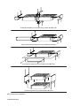
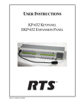
User Instructions
SSA-424
Dual Digital Hybrid
ADAM™, ADAM CS™, Zeus™ Intercom Systems
LE
V
SE EL
T
-15
PO
WE
R
-12
SY
-9
-10
dB 0dB
+1
2d
+4
B
dB
+8
4W
dB
RE LE
F S VE
EL L
ST
EM
-6
A
-3
0
2
+3
+6
1
BA
L
TW
1
+9
T
O
+1 4W
2
CH
AN
SE
L
2
TO
2W
LE
V
SE EL
T
BA
L
-15
-12
SY
-9
-10
dB 0dB
+1
2d
+4
B
dB
+8
4W
dB
RE LEV
F S EL
EL
ST
EM
-6
B
-3
0
1
2
BA
L
+3
+6
TW
1
+9
TO
4
2 W
+1
CH
AN
SE
L
TO
2W
2
TM
BA
L
SS
A-
42
9350-7638-000 Rev C 10/04
4
PROPRIETARY NOTICE
The RTS production information and design disclosed herein were originated by and are the property of Telex Communications, Inc. Telex reserves all
patent, proprietary design, manufacturing, reproduction, use and sales rights thereto, and to any article
disclosed therein, except to the extent rights are
expressly granted to others.
COPYRIGHT NOTICE
Copyright 2004 by Telex Communications, Inc. All
rights reserved. Reproduction in whole or in part
without prior written permission from Telex is prohibited.
UNPACKING AND INSPECTION
Immediately upon receipt of the equipment, inspect
the shipping container and the contents carefully for
any descrpepancies or damage. Should there be
any, notify the freight company and the dealer at
once.
WHAT’S IN THIS PACKAGE?
WARRANTY INFORMATION
For Warranty Information, see the enclosed warranty
card.
CUSTOMER SUPPORT
Technical questions should be directed to:
Customer Service Department
RTS/Telex
12000 Portland Ave South
Burnsville, MN 55337 U.S.A.
Phone: 1-800-392-3497
Fax:
1-800-323-0498
2 SSA-424 USER MANUAL
RETURN SHIPPING INSTRUCTIONS
Procedure for Returns
If a repair is necessary, contact the dealer where this
unit was purchased.
If repair through the dealer is not possible, obtain a
Return Authorization from:
Customer Service Department
RTS/Telex Communications, Inc.
Phone: 1-800-392-3497
Fax:
1-800-323-0498
DO NOT RETURN ANY EQUIPMENT DIRECTLY TO
THE FACTORY WITHOUT FIRST OBTAINING A
RETURN AUTHORIZATION.
Be prepared to provide the company name, address,
phone number and a person to contact regarding the
repair, the type and quantity of equipment, a description of the problem and the serial number(s).
SHIPPING TO MANUFACTURER
All shipments of RTS products should be made via
United Parcel Service or the best available shipper,
prepaid. The equipment should be shipped in the
original packing carton; if that is not available, use
any suitable container that is rigid and of adequate
size. If a substitute container is used, the equipment
should be wrapped in paper and surrounded with at
least four inches of excelsior or similar shockabsorbing material. All shipments must be sent to
the following address and must include the Return
Authorization.
Factory Service Department
Telex Communications, Inc.
1930 West 1st Street
Blue Earth, MN 56013 U.S.A.
Upon completion of any repair the equipment will be
returned via United Parcel Service or specified
shipper collect.
Contents
1 Description and Specifications ........................................................................................................5
1.1 GENERAL DESCRIPTION ..................................................................................................................5
1.2 GENERAL FEATURES .......................................................................................................................5
1.3 FRONT AND BACK PANEL DESCRIPTIONS ............................................................................................6
1.3.1 FRONT PANEL .........................................................................................................................6
1.3.2 BACK PANEL ...........................................................................................................................6
1.4 SPECIFICATIONS .............................................................................................................................6
2 Installation .......................................................................................................................................7
2.1 UNPACKING AND INSPECTING ............................................................................................................7
2.2 MOUNTING ....................................................................................................................................7
2.3 4-WIRE AUDIO CONNECTIONS .........................................................................................................7
2.3.1 ADAM, ADAM CS, OR ZEUS AUDIO CONNECTION .....................................................................7
2.3.2 AUDIO CONNECTIONS FOR OTHER 4-WIRE COMMUNICATIONS SYSTEMS .............................................7
2.4 2-WIRE AUDIO CONNECTIONS ..........................................................................................................9
2.4.1 RTS TW AUDIO CONNECTIONS .................................................................................................9
2.4.2 AUDIOCOM AUDIO CONNECTION .................................................................................................9
2.4.3 CLEAR-COM AUDIO CONNECTION .............................................................................................10
2.4.4 OTHER 2-WIRE AUDIO CONNECTION ..........................................................................................10
2.5 4-WIRE CALL SIGNAL CONNECTIONS ...............................................................................................11
2.5.1 CALL SIGNAL CONNECTIONS FOR ADAM, ADAM CS, AND ZEUS .................................................11
2.5.2 CALL SIGNAL CONNECTIONS FOR OTHER 4-WIRE COMMUNICATON SYSTEMS ...................................13
2.5.2.1 4-WIRE CALL SEND AND CALL ENABLE/INHIBIT .....................................................................13
2.5.2.2 4-WIRE CALL RECEIVE .....................................................................................................13
2.6 2-WIRE CALL SIGNAL ..................................................................................................................14
2.6.1 CALL SIGNAL CONNECTIONS FOR AUDIOCOM, RTS TW AND CLEAR-COM ......................................14
2.6.2 CALL SIGNAL CONNECTIONS FOR OTHER 2-WIRE COMMUNICATION SYSTEM ....................................14
3 Operation ......................................................................................................................................15
3.1 GENERAL INSTRUCTIONS ...............................................................................................................15
3.2 OPERATING NOTES FOR ADAM, ADAM CS, AND ZEUS INTERCOM SYSTEMS .........................................15
4 Appendix .......................................................................................................................................16
4.1 INTERNAL ACCESS ........................................................................................................................16
4.2 MODE DIP SWITCH SETTINGS ........................................................................................................16
4.3 LEVEL DISPLAY CALIBRATION .........................................................................................................16
4.4 CALL SIGNAL OPTION CARD INSTALLATION .......................................................................................17
SSA-424 USER MANUAL 3
4 SSA-424 USER MANUAL
Peak Reading Level Meters: Quick and accurate
visual audio level adjustment. No extra setup equipment or guesswork is required.
1
Description and
Specifications
1.1
GENERAL DESCRIPTION
The SSA-424 Dual Digital Hybrid intervaces two, 2wire intercom lines to two, 4-wire intercom lines.
Unlike earlier analog hybrids, the SSA-424 features
advanced digital signal processing to achieve
automatic nulling of the 2-wire lines. Plus, each
hybrid features convenient peak-reading level
meters to quickly match the levels between the lines
that are being interfaced. The result is easy and
accurate setup. With the SSA-424, all need for test
tones, nulling adjustments and ducking adjustments
have been eliminated.
Compatible 2-wire intercom systems include RTS™
TW, Audiocom®, and Clear-Com®. Compatible 4wire intercom systems include Telex’s ADAM™,
ADAM™CS, and Zeus™ Digital Matrix Intercom
Systems.
The SSA-424 is also available with optional call
signal interfacing. This option provides bidirectional
call signal compatibility between the 2-wire and 4wire intercom systems.
With features like digital signal processing, peakreading level meters and optional call signal interfacing, the SSA-424 Dual Digital Hybrid assures ease
of setup and maximum transparency between
intercom systems.
1.2 GENERAL FEATURES
Two Independent Hybrids: Interface two separate
2-wire lines to two separate 4-wire lines.
Direct ADAM/Zeus Audio Connection: Accepts
standard ADAM/Zeus DB9 or RJ11 keypanel cables.
Transformer Isolated: All audio inputs and outpus
are transformer isolated to prevent ground loops and
hum.
Call Signal Option: Detects call signals from any of
the compatible 2-wire intercom systems, and then
provides a +5VDC output to the 4-wire intercom
system. Accepts a contact closure input from the 4wire system and converts it to the call signal format
required by the 2-wire system. The SSA-424 can be
directly connected to an ADAM, ADAM CS, or Zeus
GPI (General Purpose Interface). GPI inputs can be
programmed to activate call signals and audio paths
to any of the available types of communication within
the 4-wire system, including intercom ports, camera
ISO circuits, IFB circuits, etc. GPI outputs can be set
up to place calls only from a specific keypanel within
the 4-wire system, or from any keypanel within the 4wire system that wishes to call the 2-wire system.
Half-rack Wide, 1RU High: Two SSA-424’s fit into a
single rack space. Compatible with RTS TW rack
mount hardware. Can be mixed with other TW
equipment.
Universal Power Pack: Ready for worldwide use.
Automatically accepts any mains voltage from 100250 VAC, 50/60 Hz. Power pack equipped with
locking DIN connector for attachment to the SSA424.
Automatic Nulling: Digital hybrids eliminate all
nulling and ducking adjustments. Quick, trouble-free
setup. Puts an end to concerns about echo and
feedback when interfacing 2-wire lines.
LEVEL
SET
SYSTEM A
TO
4W
-15 -12
-9
-6
-3
0
+3
+6
+9 +12
LEVEL
SET
SYSTEM B
TO
4W
-15 -12
-9
-6
0
-3
+3
+6
+9 +12
TO
2W
+4dB
0dB
-10dB
2
+8dB
+12dB
1
OFF
BAL
OFF
2W CHAN SEL
1
POWER
2
TO
2W
+4dB
0dB
-10dB
1
OFF
BAL
OFF
2W CHAN SEL
1
BAL
4W LEVEL
REF SEL
AUX
2
+8dB
+12dB
4W LEVEL
REF SEL
Telex Communications, Inc., Made in U.S.A.
BAL
TM
AUX
J4B
2
SSA-424
J5 POWER
+5V 3A
+15V 1.6A
-15V 0.3A
J4A
RTN
+5V
J3B
J2B
4 WIRE SYSTEM
J1B
J1A
2 WIRE SYSTEM
+15V
J2A
J3A
4 WIRE SYSTEM
-15V
RTN
Figure 1. SSA-424 Reference View
SSA-424 USER MANUAL 5
1.3
FRONT AND BACK PANEL DESCRIPTIONS
1.4
1.3.1
FRONT PANEL
2-Wire Ports
Input/Output Impedance: 5,000 ohms, nominal
Operating Level: -10dBu to 0 dBu, nominal
Level Adjustment Range: ±12dB
There is a power ON/OFF and call indicator at the left
of the front panel. This indicator lights continuously
when the SSA-424 is turned on and flashes when an
incoming call signal is detected. The remainder of
the front panel is divided into controls and indicators
for the two separate hybrids, labeled SYSTEM A and
SYSTEM B. For each hybrid, there is a 10-segment,
peak reading level meter to display the 4-wire output
level (TO 4W). There is a recessed level set control
to the left of the 4-wire meter (LEVEL SET) and there
is also a recessed, 5-position range select control for
the 4-wire output (4W LEVEL REF SEL). Under the
4-wire meter, is an identical meter for the 2-wire
output level, and there is a recessed level set control
for the 2-wire output to the left of the meter. Under
the 2-wire meter, there is a recessed, 5-position
selector. The selector has two OFF positions for
when no 2-wire input is connected. The three
remaining switch positions select the 2-wire system
as follows: position 1 selects RTS TW channel 1;
position 2 selects RTS TW channel 2 or a Clear-Com
channel; the BAL position selects an Audiocom
balanced channel. There are 3 LED indicators to
display the current selection (2W CHAN SEL).
1.3.2
BACK PANEL
The power pack connector is located at the right end
of the back panel. This is a locking DIN connector.
The remainder of the back panel is divided into
connectors for the two separate hybrids. Connectors
are labeled with “J” numbers followed fy “A” or “B” to
indicate system A or system B. For each hybrid,
there is an AUX connector. This is used to connect
to/from the optional call signal card. Below the AUX
connector, there are both a DB9F connector and an
RJ11 connector for 4-wire intercom connection.
These are directly compatible with standard ADAM/
Zeus keypanel cables. Next to the 4-wire connectors,
there is a 3-pin female XLR audio connectorfor
connection to the 2-wire intercom system. The pinout of this connector is determined by the position of
the TW CHAN SEL control on the front panel.
6 SSA-424 USER MANUAL
SPECIFICATIONS
4-Wire Ports
Input Impendance: 10k ohms, nominal
Output Impedance: 200 ohms
Operating Levels: -10 dBu, 0 dBu, +4 dBu, +8
dBu, +12 dBu
System to System
Frequency Response:200 Hz to 4.5 kHz, +1/-6dB
S/N Ratio (Ref 1 kHz, 0 dB@2-wire): TBD
Crosstalk: TBD
Environmental
Operating Temp: -20°C to 50°C (-4°F to 122°F)
Storage Temp: -40°C to 85°C (-40°F to 185°F)
Humidity: 0 to 95%, non-condensing
Mains Voltage
100 to 250 VAC, 50/60 Hz
Dimensions
1.72” (44mm) high x 8.19” (208mm) wide x 8.0”
(204mm) deep
Weight
5.0 lbs (2.3kg)
Finish
Thermoplastic front panel, almunimum case, light
gray finish
Approvals
UL, CSA, UDE, CE
Specifications subject to change without notice.
2
Installation
2.1
UNPACKING AND INSPECTING
Immediately upon receipt of the equipment, carefully
inspect the shipping container and the contents for
any discrepancies or damage. Should there be any,
notify the freight company and the dealer at once.
The following items are included:
Qty
1
1
1
1
Description
SSA-424 Dual Digital Hybrid
Power Pack with cord,100-250 VAC, 50/60Hz
Warranty Card
User Instruction Manual
2.2
MOUNTING
Place the SSA-424 on a desktop, or install it in an
equipment rack using an RTS MCP Rack Mount Kit.
Several rack mount options are available (Figure2,
page 8). There are no special ventilation requirements for the SSA-424, but allow for ventilation
around the power pack.
✏ If the SSA-424 has the call signal option, the
power indicator flashes whenever a call
signal is received from either 2-wire line, and
activity on the level display helps to indicate
which line is calling. If the SSA-424 is
positioned near the 4-wire operator, this can
be used as an incoming call indication for the
4-wire system, if desired (although other
methods are available as described in
paragraph 2.5).
✏ You may wish to read about the internal
mode DIP switches before mounting the
SSA-424. For further information, see Mode
Switch Settings, page 16.
2.3
4-WIRE AUDIO CONNECTIONS
2.3.1
ADAM, ADAM CS, OR ZEUS AUDIO
CONNECTION
1 Use standard 9-pin or RJ11 keypanel cables.
Connect from one port of your intercom system
to J2A or J3A (System A connection) on the
back of the SSA-424. Connect from another
port to J2B or J3B (System B connection).
2.3.2
AUDIO CONNECTIONS FOR OTHER 4-WIRE
COMMUNICATIONS SYSTEMS
1 Construct 9-pin or RJ11 cables to connect from
you 4-wire system to the SSA-424. To connect to
the System A hybrid, use either J2A or J3A; for
the System B hybrid, use either J2Bor J3B. Pin
connections are as follows:
9-Pin Connection
Connector Type (on SSA-424 end of cable): 9-pin
male D-subminiture
Pin 1:
Pin 2:
Pin 3:
Pin 4:
Pin 5:
Pin 6:
Pin 7:
system)
Pin 8:
system)
Pin 9:
No connection
No connection
No connection
Balanced Audio + output (to 4-wire
system)
Balanced Audio - output (to 4-wire
system)
No connection
Balanced Audio - input (from 4-wire
Balanced Audio + input (from 4-wire
No connection
RJ11 Connection
Connector Type (on SSA-424 end of cable):
RJ11 plug
Pin 1:
Pin 2:
Pin 3:
Pin 4:
Pin 5:
Pin 6:
No connection
Balanced Audio + input (from 4-wire
system)
Balanced Audio + output (to 4-wire
system)
Balanced Audio - output (to 4-wire
system)
Balanced Audio - input (from 4-wire
system)
No connection
2 On the SSA-424 front panel, set the 4W LEVEL
REF SEL switches to the position which most
closely matches the audio input and output levels
of your 4-wire system. If you don’t know the
levels, select +4dB for now.
2 On the SSA-424 front panel, set the 4W
LEVEL REF SEL switches to the +8dB position.
SSA-424 USER MANUAL 7
Side-By-Side Rack Mount Configuration Using an MCP1 Rack Mount Kit
Single-unit Rack Mount Configuration Using an MCP2 Rack Mount Kit
Console Mount Configuration Using an MCP3 Console Mount Kit
Tandem Configuration Using an MCP4 Tandem Mount Kit
Figure 2. Rack mount configurations
8 SSA-424 USER MANUAL
2.4.2
2.4.1
RTS TW AUDIO CONNECTIONS
1 Use standard TW intercom cables. Note, standard TW system cables can carry either one or
two channels, while each hybrid in the SSA-424
can only interface one TW channel to one 4-wire
channel (which channel is determined by the
front panel 2W CHAN SEL switch). If your TW
system cable is only carrying one channel, or if
you only need to connect one of two channels,
connect directly to J1A (System A) or J1B
(System B). If you TW system cable is carrying
two channels, and you want to connect both, use
a TW-5W or similar device as shown in Fig. 3.
✏ The SSA-424 features internal DC isolation.
You can therefore connect the SSA-424 to
powered TW cables, and it will not draw any
power from the TW system.
2 On the SSA-424 front panel: For each hybrid
(System A or System B) set the 2W CHAN SEL
switch to the appropriate position. To interface to
TW channel 1, select position 1; for TW channel
2, select position 2.
✏ If the System A or System B hybrid will not
be used, set its 2W CHAN SEL switch to
either OFF position.
AUDIOCOM AUDIO CONNECTION
1 You can directly connect standard Audiocom 1channel cables. Connect one Audiocom channel
to the J1A connector on the back of the SSA-424
(System A). Connect a second Audiocom
channelto the J1B connector (System B). If your
Audiocom system uses 2-channel cables, use a
JB-2 Junction Box to split the channels (Figure
4).
✏ The SSA-424 features internal DC isolation.
You cn therefore connect the SSA-424 to
powered Audiocom cables, and it will not
draw any power from the Audiocom system.
2 On the SSA-424 front panel, set the 2W CHAN
SEL switches for System A and System B to the
BAL position.
✏ If the System A or System B hybrid will not
be used, set its 2W CHAN SEL switch to
either OFF position.
CH 1 AND 2
FROM AUDIOCOM
INTERCOM SYSTEM
LINES 1&2
TW CABLE PIN-OUT
PIN 1 COMMON
PIN 2 CH 1
PIN 3 CH 2
LINE 2
2-WIRE AUDIO CONNECTIONS
JB-2
LINE 1
2.4
FROM RTS TW
INTERCOM SYSTEM
CH 2
CH 1
SSA-424
PUSH
TW-5W
AUX
Telex Communications, Inc., Made in U.S.A.
AUX
J4B
J5 POWER
+5V 3A
+15V 1.6A
-15V 0.3A
J4A
RTN
+5V
J3B
J2B
4 WIRE SYSTEM
J1B
J1A
2 WIRE SYSTEM
+15V
J2A
J3A
4 WIRE SYSTEM
-15V
RTN
Figure 4. Using a JB-2 Junction Box to split a 2-channel
Audiocom cable into two 1-channel cables.
AUX
SSA-424
Telex Communications, Inc., Made in U.S.A.
AUX
J4B
J5 POWER
+5V 3A
+15V 1.6A
-15V 0.3A
J4A
RTN
+5V
J3B
J2B
4 WIRE SYSTEM
J1B
J1A
2 WIRE SYSTEM
+15V
J2A
J3A
4 WIRE SYSTEM
-15V
RTN
Figure 3. Using a TW-5W to connect two TW channels to the
SSA-424.
SSA-424 USER MANUAL 9
2.4.3
CLEAR-COM AUDIO CONNECTION
1 Use standard Clear-Com 3-pin cables. Connect
one Clear-Com party line to the J1A connector
on the back of the SSA-424 (System A). Connect a separate Clear-Com party line to the J1B
connector (System B).
✏ The SSA-424 features internal CD isolation.
You can therefore connect the SSA-424 to
powered Clear-Com cables, and it will not
draw any power from the Clear-Com system.
2 On the SSA-424 front panel, set the System A
and System B 2W CHAN SEL switches to
position 2.
✏ If the System A or System B hybrid will not
be used, set its 2W CHAN SEL switch to
either OFF position.
2.4.4
OTHER 2-WIRE AUDIO CONNECTION
1 Use the J1A connector on the back of the SSA424 to connect one 2-wire line to the System A
hybrid. Use the J1B connector to connect a
second 2-wire line to the System B hybrid. The
pin configuration for the J1A and J1B connectors
depends on whether you are connecting a
balanced or unbalanced 2-wire line:
Balanced Configuration
Pin 1:
Pin 2:
Pin 3:
No connection
Balanced Audio + Input/Output
Balanced Audio - Input/Output
There are two possible configurations for unbalanced connection:
Unbalanced Configuraton 1
Pin 1:
Pin 2:
Pin 3:
Audio Common
Audio + Input/Output
No connection
Unbalanced Configuration 2
Pin 1:
Pin 2:
Pin 3:
Audio Common
No connection
Audio + Input/Output
2 On the SSA-424 front panel, set the CHAN SEL
switches as follows:
• Balanced Configuration: set the CHAN SEL
switches to the BAL position
• Unbalanced Configuration 1: set the CHAN
•
SEL switches to position 1.
Unbalanced Configuration 2: set the CHAN
SEL switches to position 2.
✏ If the System A or System B hybrid will not
be used, set its 2W CHAN SEL switch to
either OFF position.
10 SSA-424 USER MANUAL
2.5
Table 1. GPI Connector Pin-out
(ADAM, ADAM CS, and Zeus)
4-WIRE CALL SIGNAL CONNECTIONS
✏ These connections require the call signal
option.
2.5.1
CALL SIGNAL CONNECTIONS FOR ADAM,
ADAM CS, AND ZEUS
You can use the General Purpose Interface (GPI)
connector to interface call signals. The pin-out of the
connector is the same for all of these intercom
systems (Table 1).
ADAM GPI Connector: XCP-ADAM-MC, J11
ADAM CS GPI Connector: J903
Zeus GPI Connector: J27
If your intercom system is equipped with a UIO-256
Universal Input/Output Frame, you can also use that
for connections (Tables 2 and 3, page 12).
Pi n No .
Fu n c t i o n
1
GPI Input #1 High (5-18 VDC)
2
GPI Input #2 High (5-18 VDC)
3
GPI Input #3 High (5-18 VDC)
4
GPI Input #4 High (5-18 VDC)
5
GPI Input #5 High (5-18 VDC)
6
GPI Input #6 High (5-18 VDC)
7
GPI Input #7 High (5-18 VDC)
8
GPI Input #8 High (5-18 VDC)
9
Common*
10
Common*
11
Common*
12
Common*
13
Common*
Typical GPI connections are shown in Figure 5.
Note, the example uses GPI outputs #1 and #2 and
GPI input #1. You may substitute other GPI inputs
and outputs.
14
GPI Out #1
15
GPI Out #2
16
GPI Out #3
17
GPI Out #4
IMPORTANT NOTE FOR AZEDIT USERS: AZedit
version 1.06 includes a feature which allows you to
invert the action of the GPI outputs. By default, these
outputs are set to duplicate the actio of the RTS
FR9528 Relay Frame accessory. This is the correct
setting for use with the SSA-424. To check the
AZedit setting, select Intercom Configuration in the
Options menu. Click on the Options tab, then verify
that Configure onboard GPI outputs in FR9528
mode is selected.
18
GPI Out #5
19
GPI Out #6
20
GPI Out #7
21
GPI Out #8
22
Common*
23
Common*
As an alternative to using the GPI, you can use
external components to send and receive call signals
as described in paragraph 2.5.2.
TO SSA-424
AUX CONNECTOR
(SYSTEM A OR B)
24
Common*
25
Common*
*Use any available common pin with any GPI input or
output.
DB9F CABLE CONNECTOR PIN NUMBERS
(View from solder or crimp side)
CLEAR-COM APPLICATION NOTE: IF A
CALL ENABLE/INHIBIT SWITCH IS NOT
USED, A JUMPER MUST BE
INSTALLED TO ENABLE CALL SIGNALING.
THE JUMPER IS NOT REQUIRED FOR
ANY OTHER APPLICATION.
1
2
3
4
5
TO GPI IN COMMON
6
7
8 9
TO GPI IN #1 (4-WIRE CALL RECEIVE INPUT)
FROM GPI OUT #2 (OPTIONAL CALL ENABLE/INHIBIT CONTROL)
FROM GPI OUT #1 (4-WIRE CALL SEND OUTPUT)
GPI OUT COMMON (SEE UIO-256 APPLICATION NOTE)
UIO-256 APPLICATION NOTE: GPI OUT - AT THE UIO-256 END, USE THE NORMAL OPEN (NO) CONTACT
FOR GPI OUT CONNECTION, AND USE THE RELAY COMMON CONTACT FOR THE COMMON CONNECTION.
GPI IN - USE THE INPUT HIGH PIN FOR THE GPI IN CONNECTION, AND USE THE COMMON PIN FOR THE
COMMON CONNECTION.
Figure 5. Call signal connections for ADAM, ADAM CS, or Zeus Intercom Systems. This example usesGPI outputs #1 and #2 and
GPI input #1; however, you may use any other available GPI inputs and outputs. The Call Enable/Inhibit connection is optional. It gives
you the ability to disable call signaling using a GPI output. However, when connecting to a Clear-Com intercom system, if an enable/
inhibit switch is not connected, a jumper must be installed as shown to enable call signaling. The jumper should not be installed for any
other application. Note, you DO NOT have to use GPI outputs for call signaling or call enable/inhibit: you can use simple switches instead
as shown in Figure 6.
SSA-424 USER MANUAL 11
Table 2. UIO-256 GOI Inputs Connector (J7)
GPI In p u t Nu m b er s *
GPI In p u t Pi n Nu m b er s
UIO-256
Fr am e # 1
UIO-256
Fr am e #2
UIO-256
Fr am e #3
UIO-256
Fr am e #4
Co m m o n
In p u t Hi g h t
(5-18 VDC)
1
2
3
4
17
18
19
20
33
34
35
36
49
50
51
52
9
10
11
12
34
35
36
37
5
6
7
8
21
22
23
24
37
38
39
40
53
54
55
56
13
14
15
16
38
39
40
41
9
10
11
12
25
26
27
28
41
42
43
44
57
58
59
60
1
2
3
4
26
27
28
29
13
14
15
16
29
30
31
32
45
46
47
48
61
62
63
64
5
6
7
8
30
31
32
33
* Dependent on UIO-256 DIP Switch SW1 Settings for Input/Output Range as summarized in
the UIO-256 Manual
Table 3. UIO-256 GPI Outputs Connector (J5)
GPI Ou t p u t Nu m b er s *
Rel ay Co n t ac t Pi n Nu m b er s **
UIO-256 #1
UIO-256 #2
UIO-256 #3
UIO-256 #4
No r m al
Cl o s ed
(NC) Co n t ac t
Co m m o n
Co n t ac t
No r m al Op en
(NO) Co n t ac t
1
2
3
4
17
18
19
20
33
34
35
36
49
50
51
52
38
39
41
42
13
14
16
17
40
15
43
18
5
6
7
8
21
22
23
24
37
38
39
40
53
51
55
56
19
20
22
23
46
21
49
24
9
10
11
12
25
26
27
28
41
42
43
44
57
58
59
60
26
27
29
30
1
2
4
5
28
3
31
6
13
14
15
16
29
30
31
32
45
46
47
48
61
62
63
64
32
33
35
36
7
8
10
11
34
9
37
12
44
45
47
48
* Dependent on UIO-256 DIP Switch SW1 Settings for Input/Output Range as summarized in the UIO-256 manual.
12 SSA-424 USER MANUAL
2.5.2
CALL SIGNAL CONNECTIONS FOR OTHER 4WIRE COMMUNICATON SYSTEMS
2.5.2.1 4-WIRE CALL SEND AND CALL ENABLE/INHIBIT
The SSA-424 accepts a switch-contact input from the
4-wire system and then generates a call signal output
to the 2-wire system. The SSA-424 also accepts an
optional switch contact input to enable or inhibit call
signaling between the 4-wire and 2-wire systems.
Figure 6 shows the typical connections.
DB9F CONNECTOR PIN NUMBERS
(View from solder or crimp side)
CLEAR-COM APPLICATION NOTE:
IF A CALL ENABLE/INHIBIT
1
2 3 4 5
SWITCH IS NOT USED, A JUMPER
MUST BE INSTALLED TO ENABLE
6 7 8 9
CALL SIGNALING. THE JUMPER IS
NOT REQUIRED FOR ANY OTHER
APPLICATION.
2.5.2.2 4-WIRE CALL RECEIVE
The SSA-424 receives call signals from the 2-wire
system, then converts this to relay contact closure for
use as a 4-wire call receive indication. The SSA-424
also provides +5 VDC which can be connected to the
relay contacts to generate a DC output signal instead
of a contact closure. Connections for simple contact
closure and DC output signal are shown in Figure 7.
✏ The SSA-424 power indicator flashes
whenever a call signal is received from either
2-wire line. This can be used as an incoming
call indication for the 4-wire system, if
desired, and the level display should provide
an indication of which line is calling.
AUX
CONNECTOR
(SYSTEM A OR B)
10 Ohm
5 VDC
PIN 9
CALL ENABLE/INHIBIT
PIN 3
4-WIRE CALL SEND
PIN 4
COMMON
PIN 8
Figure 6. Typical call send and call enable/inhibit connections
for a 4-wire intercom system.
PIN 5
DC COMMON
SSA-424 INTERNAL CIRCUIT FOR CALL SIGNAL
OUTPUT TO 4-WIRE INTERCOM SYSTEM
TO SSA-424 AUX CONNECTOR
DB9F CABLE CONNECTOR PIN NUMBERS
(View from solder or crimp side)
1
2
6
3
7
4
8
5
9
TO 4-WIRE SYSTEM
SIMPLE SWITCH CONTACT CLOSURE TO 4-WIRE
SYSTEM WHEN 2-WIRE SYSTEM CALLS
OPEN CIRCUIT FOR NO CALL
TO SSA-424
AUX CONNECTOR
(SYSTEM A OR B)
DB9F CABLE CONNECTOR PIN NUMBERS
(View from solder or crimp side)
1
2
3
4
5
TO 4-WIRE COMMON
6
7
8 9
TO 4-WIRE + INPUT
+5VDC SIGNAL TO 4-WIRE
SYSTEM WHEN 2-WIRE SYSTEM CALLS
OUTPUT SHORTS TO COMMON FOR NO CALL
Figure 7. Call signal connections for a 4-wire intercom system
other than ADAM, ADAM CS, and Zeus.
SSA-424 USER MANUAL 13
2.6
2-WIRE CALL SIGNAL
2.6.1
CALL SIGNAL CONNECTIONS FOR AUDIOCOM,
RTS TW AND CLEAR-COM
The call signals are superimposed on the audio
signal, so no separate call signal connections are
required. However, make sure that a call enable
switch or jumper is installed for Clear-Com applications as shown in Figures 5 and 6.
2.6.2
CALL SIGNAL CONNECTIONS FOR OTHER 2WIRE COMMUNICATION SYSTEM
Any other 2-wire device must be able to generate
and receive a 20kHz signal superimposed on the
audio as follows:
Balanced Audio Configuration
Pin1:
No connection
Pin 2:
Balanced 20 kHz + Input/Output
Pin 3:
Balanced 20 kHz - Input/Output
SSA-424 Signal Specifications for balanced configuration:
SSA-424 Receive: 20kHz ±100 Hz, 100mV p-p
SSA-424 Send: 20 kHz ±800 Hz, 1V p-p
Unbalanced Configuration 1
Pin 1:
20 kHz Common
Pin 2:
20 kHz Input/Output
Pin 3:
No connection
Unbalanced Configuration 2
Pin 1:
20 kHz Common
Pin 2:
No connection
Pin 3:
20 kHz Input/Output
SSA-424 Signal Specifications for unbalanced
configurations:
SSA-424 Receive: 20 kHz ±100 Hz, 0.3Vrms
SSA-424 Send: 20 kHz ±200 Hz, 100m Vrms
14 SSA-424 USER MANUAL
3
Operation
3.1
GENERAL INSTRUCTIONS
1 Attach the power pack to the SSA-424, and apply
power to all components. Confirm that the power
indicator is lit on the SSA-424 front panel.
2 The power indicator flashes when a call signal is
received fron a 2-wire line. The SSA-424 level
displays should help to confirm which line is
calling.
3 Use the level adjust trimmers (Figure 8) to fine
adjust the listen levels.
✏ For 4-wire systems other than ADAM, ADAM
CS, and Zeus, you may have to change the
setting of the 4W LEVEL REF SEL control to
establish the correct level. For 2-wire
systems other than Audiocom, TW, and
Clear-Com, you may have to adjust the level
at the 2-wire system if you cannot establish
the correct level with the 2-wire listen level
trimmers.
4-WIRE LISTEN LEVEL ADJUSTMENT
LEVEL
SET
SYSTEM A
TO
4W
-15 -12
-9
-6
-3
0
+3
+6
+9 +12
LEVEL
SET
SYSTEM B
TO
4W
-15 -12
-9
-6
0
-3
+3
+6
+9 +12
TO
2W
+4dB
0dB
-10dB
2
+8dB
+12dB
1
OFF
BAL
OFF
2W CHAN SEL
1
POWER
4W LEVEL
REF SEL
2
TO
2W
+4dB
0dB
-10dB
2
+8dB
+12dB
1
OFF
BAL
OFF
2W CHAN SEL
1
BAL
4W LEVEL
REF SEL
2
BAL
TM
SSA-424
2-WIRE LISTEN LEVEL ADJUSTMENT
Figure 8. Location of level adjust trimmers
3.2
OPERATING NOTES FOR ADAM, ADAM
CS, AND ZEUS INTERCOM SYSTEMS
Another solution is to assign a dedicated key as
a UPL resource key (which you could name
CALL). Then for each key that talks to an SSA424 hybrid, create a UPL statement that will
activate (assert) the appropriate GPI whenever
the call key AND the talk key are pressed. This
lets you use the same call key with more than
one GPI. To use this, you simply activate the call
key and the appropriate talk key. Then, when a
verbal response is received, release the call key.
4 Optional call signal input using the GPI
A. In AZedit, click GPI In on the toolbar.
This opens the GPI Setup screen.
B. Whichever GPI Input you are using for 4-wire
call receive, select that GPI input from the list
(double-click). This will open the Edit GPI
Input window.
C. In the Port Alpha list box, select the intercom
port that you named in step 1.
D. In the Key Number box, type 1. This selects
key 1 at the intercom port that you selected
in step C.
E. Select Talk Key.
F. Click Done.
G. Access keypanel setup, and select the same
intercom port that you selected in step C.
H. Make sure the setup page Main is selected.
I. Assign talk key number 1 to talk to the
intercom port that you setup in step 2. We
also recommend that you assign auto-listen
(AL) to the listen key above that talk key.
2 Key assignment, party line assignment, etc. is
the same as for any other intercom port.
5 Optional call enable control. If you connected a
GPI output for use as a call enable control, you
can assign that GPi output to any intercom key in
the 4-wire intercom system. If System A is
connected to an Audiocom or TW intercom
system, pressing the key will disable call signaling. (However, the effect is the opposite if a
Clear-Com system is connected: pressing the
key will disable the signaling.)
3 Optional call signal output using the GPI: ou can
assign the GPI output to a talk or listen key, then
activate that key to generate a call signal.
6 Send your changes to the intercom system. This
completes any required programming for ADAM,
ADAM CS, or Zeus intercom system.
1 In AZedit use port alpha setup to name each 4wire intercom port that is connected to the SSA424. Choose names which help indicate which
2-wire line is being interfaced.
Another way to generate a call signal is by
assigning the GPI output as a level 2 talk key
assignment for any key that is assigned to talk to
the SSA-424. However, this will cause the call
lights to flash on the 2-wire line during the entire
conversation.
SSA-424 USER MANUAL 15
4
Appendix
4.1
INTERNAL ACCESS
Table 4. Mode DIP Switch Settings
Sw i t c h Set t i n g s
Des c r i p t i o n
1
2
3
4
1 Remove six screws from the back cover.
2 Remove the top cover.
This provides access to all internal adjustments.
Off
Off
Off
Off
Configuration 1, Half/Full Duplex Mode
(default):
Automatically switches between modes.
Useful in situations where there is high
ambient noise. Also useful when there is
acoustic feedback.
On
Off
Off
Off
Configuration 2, Switched Full Duplex Mode:
Switches from half duplex to full duplex 3-9
seconds after conversation begins on the 4wire line. Stays in full duplex mode until 6090 seconds after conversation ceases. This
helps to keep the line quiet during perdiods of
no conversation, while permitting natural
conversation when people are talking. This is
the preferred operating mode for many
situations, and par ticularly for fast, closecoordination, team operations.
On
Off
Off
On
Configuration 3, Locked Full Duplex Mode:
Same as configuration 2, but once a hybrid
enters full-duplex mode, it stays in that mode
until power-down.
Off
Off
On
Off
Configuration4, Half/Full Duplex Mode:
Similar to configuration 1, but with higher
sensitivity.
3 For option card installation, slide the circuit board
out toward the back to remove it from the bottom
cover.
AUX
Telex Communications, Inc., Made in U.S.A.
AUX
J4B
J5 POWER
+5V 3A
+15V 1.6A
-15V 0.3A
J4A
RTN
+5V
J3B
J2B
4 WIRE SYSTEM
J1B
J1A
2 WIRE SYSTEM
+15V
J3A
J2A
4 WIRE SYSTEM
-15V
RTN
Figure 9. Location of screws for disassembly.
Half-duplex Definition: Only one side of the line
can talk at a time and the other side must wait until
the first side is done talking before responding.
RV202
RV201
Full-duplex Definition: Both sides of the line can
talk simultaneously.
S301
S302
RV102
RV101
4.3
LEVEL DISPLAY CALIBRATION
✏ This is a factory preset adjustment and
should not require readjustment.
1 On the front panel, set the 4W LEVEL REF SEL
controls to -10dB.
2 Set the 2W CHAN SEL switches to 1.
Figure 10. Locations of internal controls.
4.2
MODE DIP SWITCH SETTINGS
S301 controls the operating mode for System B and
S302 controls the operating mode for System A.
Settings are summarized in Table 4
3 Input a 1kHz, -10dBu test signal at J1A (System
A) or J1B (System B). (Pin 1, signal common;
pin 2, signal high.)
4 Adjust RV101 (System A) or RV201 (System B)
while watching the top display (TO4W). All of the
green displays should be lit and no amber
displays should be lit.
5 Remove the test signal.
16 SSA-424 USER MANUAL
6 Set the 2W CHAN SEL switches to either OFF
position.
7 Input a 1kHz, -10dBu test signal at the 4-wire
audio input. Use either connector:
9-Pin Connector
Pin 7: Balanced Audio - input
Pin 8: Balanced Audio + input
RJ11 Connector
Pin 2: Balanced Audio + input
Pin 3: Balanced Audio - input
8 Adjust RV102 (System A) or RV202 (System B)
while watching the bottom display (TO2W). All of
the green displays should be lit and no amber
displays should be lit.
9 Remove the test signal. This completes the
adjustment.
4.4
CALL SIGNAL OPTION CARD INSTALLATION
Use these instructions to install a Call Signal Option
Card in an SSA-424 that was originally ordered
without it.
1 Disassemble the SSA-424 as previously described.
2 Assemble the standoffs to the circuit board using
the supplied screws and lockwashers.
3 Connect the supplied power cable from J8 on the
option card to J303 on the main board of the
SSA-424.
4 Insert the connectors on the option card into the
connectors on the main board.
5 Use the remaining screws and lockwashers to
secure the standoffs to the main board.
6 Reassemble the SSA-424.
Figure 11. The Call Signal Option Card after installation in the
SSA-424.
SSA-424 USER MANUAL 17