1
www.zektor.com
858•748•8250
Poway, CA 92064
Suite 401
12675 Danielson Ct
ZEKTOR
Rev 1
2
3
4
5
SEL
Digital Video Switch
(Supplement to the HDMI5 User Guide)
1
HDMI5
A1
06/28/2007
A2
Home Theater Solutions
ii
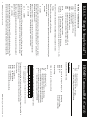
Table of Contents
The RS-232 Port .............................................................. 1
K.I.S.S.™ (Keep It Simple Serial™) .................................... 2
The K.I.S.S.™ Command Structure . . . . . . . . . . . . . . . . . . . . . . . . . . . . . . . . . . . . . . . .2
Using Bitmapped Parameters . . . . . . . . . . . . . . . . . . . . . . . . . . . . . . . . . . . . . . . . . . . .3
Command Checksums and CRC-8 Checkcodes . . . . . . . . . . . . . . . . . . . . . . . . . . .4
Clearing the Command Buffer . . . . . . . . . . . . . . . . . . . . . . . . . . . . . . . . . . . . . . . . . . .5
The Response Strings . . . . . . . . . . . . . . . . . . . . . . . . . . . . . . . . . . . . . . . . . . . . . . . . . . . .5
Response String Checksums and CRC-8 Checkcodes . . . . . . . . . . . . . . . . . . . . . .6
Master / Slave and Asynchronous Modes of Operation . . . . . . . . . . . . . . . . . . .7
The Master / Slave Mode of Operation. . . . . . . . . . . . . . . . . . . . . . . . . . . . . . . . . . . .7
The Asynchronous Mode of Operation . . . . . . . . . . . . . . . . . . . . . . . . . . . . . . . . . . .8
10
10
11
12
Checksums and CRC-8’s ................................................. 10
Checksums and CRC-8 Checkcodes Defined . . . . . . . . . . . . . . . . . . . . . . . . . . . .
Differences between a Checksum and a CRC-8 Checkcode . . . . . . . . . . . . . .
Source Code Example of Calculating a Checksum . . . . . . . . . . . . . . . . . . . . . .
Source Code Example of Calculating a CRC-8 Checkcode . . . . . . . . . . . . . . .
HDMI5 Command Ref. ................................................... 14
The HDMI5 K.I.S.S.™ Command Reference . . . . . . . . . . . . . . . . . . . . . . . . . . . . . . 14
Error Response Codes . . . . . . . . . . . . . . . . . . . . . . . . . . . . . . . . . . . . . . . . . . . . . . . . . . 14
The HDMI5 Command Set . . . . . . . . . . . . . . . . . . . . . . . . . . . . . . . . . . . . . . . . . . . . . 14
Version Query . . . . . . . . . . . . . . . . . . . . . . . . . . . . . . . . . . . . . . . . . . . . . . . . . . . 15
Power Control . . . . . . . . . . . . . . . . . . . . . . . . . . . . . . . . . . . . . . . . . . . . . . . . . . . 15
Output Mapping . . . . . . . . . . . . . . . . . . . . . . . . . . . . . . . . . . . . . . . . . . . . . . . . . 16
Front Panel Light Intensities . . . . . . . . . . . . . . . . . . . . . . . . . . . . . . . . . . . . . . 16
Save Power On Default Settings . . . . . . . . . . . . . . . . . . . . . . . . . . . . . . . . . . 17
Query Last IR Code Received. . . . . . . . . . . . . . . . . . . . . . . . . . . . . . . . . . . . . . 17
Set Learnable IR Command Codes. . . . . . . . . . . . . . . . . . . . . . . . . . . . . . . . . 18
Front Panel Button Emulation . . . . . . . . . . . . . . . . . . . . . . . . . . . . . . . . . . . . 19
Query Status . . . . . . . . . . . . . . . . . . . . . . . . . . . . . . . . . . . . . . . . . . . . . . . . . . . . 21
Control Settings . . . . . . . . . . . . . . . . . . . . . . . . . . . . . . . . . . . . . . . . . . . . . . . . . 22
Extended Control Settings . . . . . . . . . . . . . . . . . . . . . . . . . . . . . . . . . . . . . . . 24
Input Equalization & Bandwidth . . . . . . . . . . . . . . . . . . . . . . . . . . . . . . . . . . 25
Switching Delays . . . . . . . . . . . . . . . . . . . . . . . . . . . . . . . . . . . . . . . . . . . . . . . . 26
Relay Control . . . . . . . . . . . . . . . . . . . . . . . . . . . . . . . . . . . . . . . . . . . . . . . . . . . . 26
Relay Settings . . . . . . . . . . . . . . . . . . . . . . . . . . . . . . . . . . . . . . . . . . . . . . . . . . . 27
HDMI5 Component Video Switch
HDMI5 Command Ref. (Cont’d)
HDMI5 Component Video Switch 29
1,0,,0,0
1,1,time,0,0
1,0,time,vid_msk,aud_msk
1,1,time,vid_msk,aud_msk
28 HDMI5 Component Video Switch
RLS
RLS
RLS
RLS
Set to “Mode 0”, ‘timing’ values are ignored
Set to “Mode 1”, time not set to 0
Set to “Mode 3”, at least one mask not set to 0
Set to “Mode 4”, at least one mask not set to 0
The following examples set Relay ‘1’ to the four different modes:
Relays become active for a momentary amount of time when either a video or audio input is
selected and the bit for that input is set to ‘1’ in the ‘vid_msk’ or ‘aud_msk’ parameter. The ‘time’
value given is how long a relay remains active before turn off.
Mode 4
Relays become active when either a video or audio input is selected and the bit for that input
is set to ‘1’ in the ‘vid_msk’ or ‘aud_msk’ parameter. The ‘time’ value given is how long a relay
remains active after a input is selected that does not match a ‘1’ bit in ‘vid_msk’ or ‘aud_msk’.
Mode 3
Relays stay on for a momentary amount of time when activated by a button press, or RS-232
command. The value ‘time’ indicates the amount of time the relay stays on (in 15.626ms increments). If time is set to ‘0’, then relays will toggle like Mode 1. Selecting inputs has no affect on
the relays.
Mode 2
Relays toggle when activated by button press, or RS-232 command. Selecting inputs has no
affect on the relays, and any ‘time’ value given is ignored.
Mode 1
HDMI5 Command Ref. (Cont’d)
-
No Connect
TX
RX
No Connect
GND
6
7
8
9
-
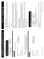
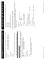
Baudrate:
Data Bits:
Stop Bits:
Parity:
9600
8
1
NONE
The port settings used by the HDMI5 are:
1
2
3
4
5
Pin definitions:
No
No
No
No
9 8 7 6
HDMI5 Component Video Switch
Connect
Connect
Connect
Connect
5 4 3 2 1
The RS-232 port is a female type DE-9 connector (sometimes mistakenly referred to as a DB-9
connector) with the following pinout:
The HDMI5 can also be used with any USB to RS-232 conversion cable, these are all typically
straight through cables.
The RS-232 port on the HDMI5 is the same format, and pinout, as a PC-modem, and uses the
same type of cable as a standard serial modem would, which is a standard straight through
cable. Do not use a cable that is marked as a “Null Modem” cable.
The RS-232 Port
1
2
K.I.S.S.™ (Keep It Simple Serial™)
The K.I.S.S.™ Command Structure
= The Zektor device being controlled.
= A PC or other system, used to control the Zektor device.
= A decimal value that may, in some cases, be prefixed with ‘+’ or ‘-’ (+,-,0-9).
= An ASCII Carriage Return (‘0D’ hex)
= Line Feed (‘0A’ hex)
= An Escape character (‘1B’ hex)
= A command, consisting of only alpha characters (A-Z, a-z).
= An error code value, consisting of only decimal digits (0-9).
The following conventions are used to describe the protocol:
<CR>
<LF>
<ESC>
CMD
ERR
Device
Controller
Parameter
A K.I.S.S.™ command in its simplest form is a CMD following by a <CR> for instance:
V<CR>
This will return the version number of a Zektor device.
P1<CR>
A command can have a variable number of parameters with optional whitespace(s) following the
command, for instance:
or
P 1<CR>
will turn on the power of most Zektor devices. The spaces between the ‘P’ and ‘1’ are optional.
Since commands consist of alpha characters only, there can never be a ‘P1’ command and ‘P1’
will always be interpreted as ‘P 1’.
LI 3 13<CR>
When a command has more than one parameter, the parameters are separated by either
whitespace(s) or a comma, or both whitespace(s) and a comma, for instance:
or
LI 3 , 13<CR>
will set the lower and upper LED front panel intensity levels of most Zektor devices. Once again
the space between the command and 1st parameter is optional. Space(s) may also appear
before and after the comma.
The comma is optional between parameters except when it is necessary to indicate a default
parameter, for instance:
LI ,13<CR>
would set the upper intensity level of the front panel LEDs without affecting the lower level. The
comma is used to indicate the 1st parameter is not supplied and the default value should be
used (in this case the value defaults to the current setting, leaving the value unchanged). The
HDMI5 Component Video Switch
New settings
Query ‘rly_n’ settings
Query both relay settings
= Relay number (1 or 2).
= State of relay (0=Off, 1=On, 2=Toggle).
= If present, settings are backed up in EEPROM.
HDMI5 Command Ref. (Cont’d)
Where:
rly_n
state
$
Relay Settings
Setup the behavior of the relays.
RLS rly_n,mom,time,vid_msk,aud_msk,$
RLS rly_n,?
RLS ?
Response String:
=RL rly_n,mom,time,vid_mask,aud_mask
Where:
rly_n
= Relay number (1 or 2).
mom
= Momentary mode (0=Static, 1=Momentary).
time
= Relay delay time in 15.626 millisecond increments.
vid_msk = A bitmapped value of video channels affecting relay.
aud_msk = A bitmapped value of audio channels affecting relay.
$
= If present, settings are backed up in EEPROM.
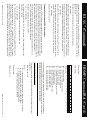
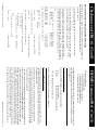
‘vid_msk’ and ‘aud_msk’ are a bitmapped parameters, mapped as follows:
+128 +64 +32 +16 +8 +4 +2 +1
7
6
5
4
3
2
1
0
0
0
0 IN5 IN4 IN3 IN2 IN1
0
0
0
0
0
0
0
0
- 0 input does not affect relay. 1=Input triggers relay when input is selected.
- Reserved, always set to 0.
Decimal Value
Bit Position
Name
Factory Settings:
IN1-IN5
0
This command allows setting up all relay modes of operation. The four relay modes specified in
the user manual are based on an interaction of the parameters supplied.
= Toggle Mode.
= Momentary Mode.
= Channel Select.
= Channel Select Momentary Mode.
The four modes are:
Mode 1
Mode 2
Mode 3
Mode 4
HDMI5 Component Video Switch 27
+128 +64 +32 +16
7
6
5
4
0
0
0
0
0
0
0
0
- 0=Vertical sync pass through.
- 0=Horizontal sync pass through.
- 0=Horizontal dejitter off.
- Reserved, always set to 0.
+4 +2 +1
2
1
0
DJT HEN VEN
0
0
0
1=Vertical sync always low.
1=Horizontal sync always low.
1=Horizontal dejitter on.
+8
3
0
0
Set new settings
Query for current settings
Query for current settings
26 HDMI5 Component Video Switch
=RL rly_n,state
Response String:
RL rly_n,state,$
RL rly_n,?
RL ?
Controls the state of the relays.
Relay Control
Set the state of relay ‘rln’
Read the state of relay ‘rln’
Read the state of both relays
Where:
video_delay = Video switching delay in 15.626 millisecond increments.
audio_delay = Audio switching delay in 15.626 millisecond increments.
$
= If present, settings are backed up in EEPROM.
=SD video_delay,audio_delay
Response String:
SD video_delay,audio_delay,$
SD ?
SD
Allows setting of the Video and Audio switching delays.
Switching Delays
VEN
HEN
DJT
0
Decimal Value
Bit Position
Name
Factory Settings:
‘clt’ is a bitmapped parameter, mapped as follows:
HDMI5 Command Ref. (Cont’d)
LI<CR>
LI ?<CR>
- 0=Master / Slave mode.
- 0=Disable Front Panel.
- 0=Disable IR.
- 0=Turn off IR Sensor.
- 0=Turn off IR Jack.
- 0=Disable CS and CRC-8
- 0=Append Checksums or,
- Reserved, always set to 0.
+2
1
FP
1
+1
0
AS
0
1=Asynchronous Mode.
1=Front Panel Enabled
1=Enable IR.
1=Turn on IR Sensor.
1=Turn on IR Jack.
1=Append either Checksums or CRC-8 to responses.
1=Append CRC-8’s to reponses.
+128 +64 +32 +16 +8 +4
7
6
5
4
3
2
0 CRC CSE IRJ IRS IRE
0
0
0
1
1
1
HDMI5 Component Video Switch
The ‘Decimal Value’ in the table’s header, refers to the values added together to create the deci-
This indicates the parameter ‘settings’ is bitmapped parameter, followed by a description of what
each bit represents.
AS
KB
IRE
IRS
IRJ
CSE
CRC
0
Decimal Value
Bit Position
Name
Factory Settings:
Where ‘settings’ is a bitmapped parameter:
XS settings<CR>
An example of a command that uses a bitmapped parameter is the CVS4’s “XS settings<CR>”
command, which is defined like this:
Binary arithmetic is used to represent bitmapped parameters, it is assumed the reader has some
familiarity with binary arithmetic.
Some commands accept “Bitmapped” parameters. These are decimal values that represent a
series of flags, or bits, that control, enable and/or disable different device operations.
Using Bitmapped Parameters
Most Zektor products use the K.I.S.S. command structure, the examples given here to describe
syntax, may differ slightly from the commands used by your device. Please see the “Command
Reference” section for the specific commands used by your device.
This would cause the device to issue a LED Intensity Response, (the Response String format
is described in the section entitled: “The Response String”). The whitespace before the ‘?’ is
optional.
or
Most commands can be queried for their current settings by substituting the ‘?’ for the parameter
list, or by not supplying any parameters at all. For instance to request the current LED Intensity
settings:
space before the comma is optional.
K.I.S.S.™ (Continued)
3
4
K.I.S.S.™ (Continued)
mal parameter used by the command. For instances if the bits ‘AS’ and ‘IJ’ where to be set to 1,
and the rest of the bits set to zero, the parameter value would be calculated as: 8+1, making the
parameter value: 9.
The command to directly set those two bits, and reset all the others would be:
XS 9<CR>
Individual bits of a bitmapped parameter can be set or reset without affecting the other bits, by
prefixing the bitmapped parameter with a ‘+’ to set individual bits, or a ‘-’ to reset individual bits.
For instance in the above example the bitmapped value has been set to ‘9’. If we would now like
to enable the IR remote, by setting the ‘IRE’ bit, the following command can be issued:
XS +4<CR>
The will set the ‘IR’ bit, and have no affect on the others, and the new “XS” value would be: 13
If we’d like to now disable the IR jack and the IR remote functions and the Front Panel, by clearing the ‘IRJ’, ‘IRE’ & ‘FP’ bits, we’d use the value “16+4+2”, or 22, and issue the command:
XS -22<CR>
leaving the new “XS” value to be: 1.
Command Checksums and CRC-8 Checkcodes
A checksum or CRC-8 checkcode may be appended to any command, and if given, will be
calculated by the device and compared with the given value. If a mismatch occurs an error will
be returned and the command will not be executed. This can be used to help assure reliable operation in noisy environments. Checksums are more commonly used in serial protocols, however
CRC-8 checkcodes offer a more secure means of insuring error free communications.
A checksum or CRC-8 checkcode is appended to the command by adding a semicolon (‘;’) or
colon (‘:’) suffix character followed by the checksum or checkcode.
An example of appending a checksum to a command:
LI 2,13;178<CR>
the ‘;’ indicates a checksum follows, the ‘178’ is the checksum of the command string up to and
including the ‘;’ character.
In a similar fashion a CRC-8 checkcode can be appended to a command:
LI 2,13:213<CR>
The ‘:’ indicates that a CRC-8 checkcode follows, the ‘213’ is the calculated CRC-8 checkcode.
Optional spaces are allowed before the ‘;’ and ‘:’ characters but NOT after them. The checksum
must immediately follow the ‘;’ character, and a CRC-8 checkcode must immediately follow the ‘:’
character, anything else, including whitespace, will cause a syntax error to be returned. Similarly
the <CR> must immediately follow the checksum or checkcode parameter or a syntax error will
HDMI5 Component Video Switch
HDMI5 Command Ref. (Cont’d)
Response String:
=XE settings
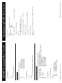
Where ‘settings’ is a bitmapped parameter:
+4096 +2048 +1024 +512 +256 +128 +64 +32 +16 +8 +4 +2 +1
12
11
10
9
8
7
6
5
4
3
2
1
0
RS2 RS1 RL2 RL1 EQU SWD CTL LMI IRC IRR BTN SEL PWR
0
0
0
0
0
0
0
0
0
0
0
1
1
- 1=Power State has changed.
- 1=Selection (Input / Output Mapping) has changed.
- 1=One or more buttons have been pressed.
- 1=A new IR code has been received.
- 1=New IR codes have been learned.
- 1=Lighting Mode or Intensity Level Settings have changed.
- 1=Control Settings have changed.
- 1=Switching delays have changed.
- 1=Equalization or Bandwidth settings have changed.
- 1=Auxiliary 1’s relay has changed states.
- 1=Auxiliary 2’s relay has changed states.
- 1=Auxiliary 1 relay’s parameters have changed.
- 1=Auxiliary 2 relay’s parameters have changed.
Decimal Value
Bit Position
Name
Factory Settings:
PWR
SEL
BTN
IRR
IRC
LMI
CTL
SWD
EQU
RL1
RL2
RS1
RS2
The ‘$’ parameter is a “Backup Control Settings” flag. If it exists, then the current settings will
be backed up in EEPROM, and will remain unchanged through a power failure. Backing up the
“Extended Control Settings” will also backup the “Control Settings”.
Input Equalization & Bandwidth
This command allows setting the equalization, bandwidth and control settings of the currently
selected input.
= Indicates the cable length equalization setting (0=Shortest, 15=Longest).
= Bandwidth setting. (0=4MHz, 1=3MHz, 2=6Mhz, 3=5MHz).
= Bitmapped control settings (See following bitmap table).
= If present, settings are backed up in EEPROM.
EQU equ,bw,ctl,$
Where:
equ
bw
ctl
$
Response string:
=EQU equ,bw,ctl
HDMI5 Component Video Switch 25
Power State changes (On / Off condition).
Selection changes (input / output mapping changes).
Front Panel modes and intensity changes
Front Panel Button Presses.
IR codes received.
New IR codes learned.
Control Settings changes.
settings
+settings
-settings
settings,$
+settings,$
-settings,$
$
?
Set the enable bits to ‘settings’.
Set enable bits indicated in ‘settings’ to 1.
Reset enable bits indicated in ‘settings’ to 0.
Set the control bits to ‘settings’, save in EEPROM.
Set bits indicated in ‘settings’ to 1, save in EEPROM.
Reset bits indicated in ‘settings’ to 0, save in EEPROM.
Back up current settings into EEPROM.
Query for current settings.
Query for current settings.
24 HDMI5 Component Video Switch
XE
XE
XE
XE
XE
XE
XE
XE
XE
The ‘AS’ in the “Control Settings” command must be set to ‘1’ to allow any Asynchronous
transmissions, if the ‘AS’ bit is set to zero, then the HDMI5 will operate solely in the Master /
Slave mode regardless of the settings of this command.
Each of the above states can be selectively set to asynchronously transmit their state changes,
or run in the Master / Slave mode. If asynchronous transmit has been disabled for one of the
options, then that option will revert to the Master / Slave mode.
•
•
•
•
•
•
•
This HDMI5 allows control over the following states:
In the Asynchronous mode of operation, the HDMI5 will transmit state changes as they occur.
This command allows individual control over which state changes will be sent.
Extended Control Settings
HDMI5 Command Ref. (Cont’d)
The Acknowledgement Response
The Error Response
The Query Response
+<CR><LF>
The Acknowledgement is always the string:
HDMI5 Component Video Switch
The response to a command string will always be an Acknowledgement or an Error Response.
+
!
=
The three possible prefix characters and their associated responses are
Each response is prefixed by a unique character. Determining which of the three responses is
received can be done simply, by examining only the first character of any response string.
There are only three valid responses in the K.I.S.S.™ protocol, anything else should be considered a communication error, including a timeout while waiting for a response.
A response will always be returned whenever a <CR> is received. There are no conditions
where a “timeout” is a valid response to any query.
The Response Strings
It is legitimate to prefix all commands with the <ESC> character to assure the buffer is always
empty before the command string is received, which may be helpful in a very noisy environment.
will return the Version Query Response string for most Zektor devices. The “dsLG%df”
represents noise that could have been in the buffer before the command string was issued. The
<ESC> clears the buffer allowing the “V;145<CR>” to be processed error free.
dsLG%df<ESC>V;145<CR>
For example:
This is useful when communications with the Zektor device is being initialized and the state of
the device is unknown. An <ESC> will clear the command buffer and reset all checksums and
CRC-8 checkcodes.
All commands are buffered and nothing is executed until the <CR> character is received. To assure that there are no extraneous characters in the command buffer, before a command string is
sent, the <ESC> character can be issued to clear the buffer and reset any checksum or CRC-8
checkcode calculations.
Clearing the Command Buffer
See: “Checksums and CRC-8’s” for more information on both, and source code examples of
calculating both Checksums and CRC-8’s as used by K.I.S.S.™.
be returned.
K.I.S.S.™ (Continued)
5
6
K.I.S.S.™ (Continued)
and the Error Response is always the string:
!ERR<CR><LF>
+1
0
AS
0
1=Asynchronous Mode.
1=Front Panel Enabled
1=Enable IR Control.
1=Turn on IR Sensor.
1=Turn on IR Jack.
1=Append either Checksums or CRC-8 to responses.
1=Append CRC-8’s, to responses.
1=Use IR Jack as +12V On / Off Control
+2
1
FP
1
Back up current settings into EEPROM.
Query for current settings.
Query for current settings.
HDMI5 Command Ref. (Cont’d)
XS $
XS ?
XS
Response String:
=XS settings
By parsing only the prefix characters ‘+’ and ‘!’, a programmer can chose to ignore the error
codes and simply look at the first characters of the response strings and use them as a pass /
fail indicator when issuing a command.
All response strings always end with a <CR><LF>.
- 0=Master / Slave mode.
- 0=Disable Front Panel.
- 0=Disable IR Control.
- 0=Turn off IR Sensor.
- 0=Turn off IR Jack.
- 0=Disable CS and CRC-8
- 0=Append Checksums,
- 0=+12V disabled
+128 +64 +32 +16 +8 +4
7
6
5
4
3
2
12V CRC CSE IRJ IRS IRE
0
0
0
1
1
1
Where ‘settings’ is a bitmapped parameter:
AS
KB
IRE
IRS
IRJ
CSE
CRC
12V
Decimal Value
Bit Position
Name
Factory Settings:
A Query Response string always starts with the ‘=’ characters and is followed by a command
string indicating the parameter being returned. This is better explained in an example.
Sent: Light Intensity Query command
Received: Acknowledgement of command
Received: Light Intensity Query Response
Here’s an example of a querying a device for its light intensity settings:
LI?<CR>
+<CR><LF>
=LI 2,13<CR><LF>
Note that a “+<CR><LF>” followed the command string. A command string is always followed
by either an Acknowledgment (as in this case) or an Error Response. This consistency allows
a driver to use a single routine to issue a command and check for an Acknowledgement or an
Error Response String, whether or not the command queries for a response.
Sent: Command characters transposed, no such command
Received: Error Response indicating unknown command
An example of an error response:
IL?<CR>
!2<CR><LF>
The ‘$’ parameter is a “Backup Control Settings” flag. If it exists, then the current settings will
be backed up in EEPROM, and will remain unchanged through a power failure. Backing up the
“Control Settings” will also backup the “Extended Control Settings”.
The IR control (IRE) and the IR jack (IRS), work differently when disabled. Disabling IR control,
by setting the ‘IRE’ bit to zero, keeps the HDMI5 from responding to any IR codes, however the
front panel sensor remains operational and any codes received can still be queried for by using
the “IR ?” command. Disabling the IR sensor (IRS) and enabling IR control (IRE), allows the
HDMI5 to respond to IR signals through the IR jack, any signal received by the IR sensor will be
ignored.
In this case the Error Response string “!2<CR><LF>” was issued instead of the acknowledgment string since the command was not recognized.
Response strings can be programmed to have checksums or CRC-8 checkcodes appended to
them, the syntax is identical to the Command Structure’s checksum and CRC-8 handling.
Disabling the IR jack, by setting the ‘IRJ’ bit to zero, completely disables the IR jack. IR commands are no longer be received through the IR jack if the ‘IRJ’ bit has been set to zero.
Response String Checksums and CRC-8 Checkcodes
Checksum and CRC-8 are turned on and off by issuing the proper command. On most devices
this is the “Control Settings” command.
The ‘IRJ’ flag and ‘12V’ are mutually exclusive. Any attempt to set them both will result in the
‘12V’ being disabled.
HDMI5 Component Video Switch 23
Only the Error Response and The Query Response strings will have checksum and CRC8 checkcodes appended to them. The Acknowledgment Response will always consist of
“+<CR><LF>”. Anything else must be assumed to be a communication error.
An example with checksumming enabled, while querying for LED intensities is:
LI?<CR>
+<CR><LF>
=LI 2,13;239<CR><LF>
HDMI5 Component Video Switch
Query for current flag values.
Query for current flag values.
+4096 +2048 +1024 +512 +256 +128 +64 +32 +16 +8 +4 +2 +1
12
11
10
9
8
7
6
5
4
3
2
1
0
RS2 RS1 RL2 RL1 EQU SWD CTL LMI IRC IRR BTN SEL PWR
0
0
0
0
0
0
0
0
0
0
0
1
1
- 1=Power State has changed.
- 1=Selection (Input / Output Mapping) has changed.
- 1=One or more buttons have been pressed.
- 1=A new IR code has been received.
- 1=New IR codes have been learned.
- 1=Lighting Mode or Intensity Level Settings have changed.
- 1=Control Settings have changed.
- 1=Switching delays have changed.
- 1=Equalization or Bandwidth settings have changed.
- 1=Auxiliary 1’s relay has changed states.
- 1=Auxiliary 2’s relay has changed states.
- 1=Auxiliary 1 relay’s parameters have changed.
- 1=Auxiliary 2 relay’s parameters have changed.
XS
XS
XS
XS
XS
XS
settings
+settings
-settings
settings,$
+settings,$
-settings,$
Set the control bits to ‘settings’
Set bits indicated in ‘settings’ to 1.
Reset bits indicated in ‘settings’ to 0.
Set the control bits to ‘settings’, save in EEPROM.
Set bits indicated in ‘settings’ to 1, save in EEPROM.
Reset bits indicated in ‘settings’ to 0, save in EEPROM.
Select the Master / Slave or Asynchronous modes of operations.
Enable / Disable the front panel switches.
Enable / Disable the IR control.
Enable / Disable the IR jack.
Enable / Disable appending Checksums or CRC-8’s to responses.
If enabled, choose whether Checksums or CRC-8’s will be appended to responses.
22 HDMI5 Component Video Switch
•
•
•
•
•
•
This command allows control over the following:
Turn on and off operational modes of the HDMI5.
Control Settings
PWR
SEL
BTN
IRR
IRC
LMI
CTL
SWD
EQU
RL1
RL2
RS1
RS2
Decimal Value
Bit Position
Name
Factory Settings:
Where ‘flags’ is a bitmapped parameter:
=Q flags
Response String:
Q ?
Q
HDMI5 Command Ref. (Cont’d)
Sent: Controller issues a query command.
Received: Acknowledgment (or possible Error) Response.
Received: Query Response.
HDMI5 Component Video Switch
In the Master / Slave mode, the Acknowledgement or Error Response will always be the next re-
LI ?<CR>
+<CR><LF>
=LI 2,13<CR><LF>
The Master / Slave mode also allows for a predictable communications flow. A communication
sequence is always started by the controller by issuing a command. The response will always be
either the Acknowledgement Response, or an Error Response, followed by (if a query command
was issued) the Query Response. For instance:
To allow for more efficient Master / Slave operations, there is a Query Status command available
to the controller that return the status state of the device as a bitmap of flags indicating which
states have changed and need querying. This allows the controller to poll, using a single command, and then based on those flag settings, issue only the commands needed to read the new
state(s) of the device.
For controllers that cannot handle having information being sent to them in the background, or at
unspecified times, the Master / Slave setting is ideal, since all state changes will be logged but
not sent until requested by the controller.
In the Master / Slave mode, the controller requests information from the device at polled
intervals. The control program assumes the role of the master, and the device is operated in the
slave mode. No information will be sent from the device without first receiving a request from the
controller.
The Master / Slave Mode of Operation
The K.I.S.S.™ protocol can be used in a Master / Slave mode, where responses are only sent
when requested, or in an Asynchronous mode, where responses are sent whenever the operational state of the device changes, such as a front panel button being pressed.
Master / Slave and Asynchronous Modes of Operation
When Response Checksums, or Response CRC-8 Checkcodes are enabled, Error Response
strings will also have checksum and CRC-8 codes appended to them.
Notice that in the first example a checksum was not appended to the “LI?” command. When
issuing a command the checksum and CRC-8 codes are sent on a command by command
basis. Anytime a checksum or a CRC-8 code is appended to a command it will be checked and
validated by the device, regardless of the “Response Checksum / CRC-8” settings.
LI?:194<CR>
+<CR><LF>
=LI 2,13:87<CR><LF>
An example with CRC-8 responses enabled is:
K.I.S.S.™ (Continued)
7
8
K.I.S.S.™ (Continued)
ated by the keyboard, making this command a bit more useful. These extended codes allow for
better control of the HDMI5.
HDMI5 Command Ref. (Cont’d)
Description
When Issued: Exits setup modes.
When returned by query: No buttons have been pressed since last the query.
Always toggle power (like Power Toggle without the need of a release code).
Discrete power on (always turns on power).
Discrete power off (always turns off power).
Sequence through inputs.
Discrete breakaway disable (always turn off breakaway).
Discrete audio breakaway.
Discrete video breakaway.
Turn on relay 1
Turn off relay 1
Turn on relay 2
Turn off relay 2
The ‘0’ button code is also device independent. Its use, and value, does not change between
Zektor devices like the other codes may (and most likely will).
The ‘0’ code has special meaning. When returned in a Query Response string it means there are
no keys waiting in the buffer. When issue by the controller, it acts like an Exit key, used to exit
setup modes, similar to pressing the Power Button, but it will be ignored if the HDMI5 is not in
the setup mode. By issuing ‘0’ codes, the HDMI5 can be returned to a known state, regardless of
any possible setup state it might be in.
Code
0
0
100
101
102
103
104
105
106
107
108
109
110
Some extended button codes are:
sponse string after a command is issued, and a Query Response will always follow an Acknowledgement Response.
The Asynchronous Mode of Operation
In the Asynchronous mode the device sends a Query Response string anytime there is a state
change. For instance when an input is changed by the user by pressing a button on the front
panel, or using a remote control, or by the IR jack, or even if a serial command has been issued,
a Query Response string indicating an input change will be sent to the controller.
The advantage if this mode is the controller can be kept constantly in sync with the device
without having to send periodic polling commands. This disadvantages are: The controller must
be able to receive the Query Response strings in the background at unspecified times, and the
communications flow is slightly more complicated.
Sent: Controller issues query command.
Received: (unsolicited) Out 1 remapped to In 3.
Received: Acknowledgment Response.
Received: (unsolicited) Power turned off.
Received: Query Response for LED intensities.
When issuing commands in the Asynchronous mode, the controller must be aware of any unsolicited Query Responses that may be interjected into the communications flow.
For example:
LI?<CR>
=O 1,3
+<CR><LF>
=P 0
=LI 2,13<CR><LF>
This represents a worst case scenario where unsolicited responses appear throughout the communication sequence.
First the “LI?<CR>” command was issued by the controller.
Query Status
In the Master / Slave mode of operation, this command is used to poll for any pending state
changes that are waiting to be read. By issuing this command and testing the returned bitmapped value, the controller can determine what has changed in the HDMI5 since the last time
it was polled.
While looking for an Acknowledgement or Error Response string, an unsolicited Query Response
is received, indicating the user has remapped Output 1 to Input 3, while the “LI?<CR>” command was being issued by the controller.
Finally the Query Response indicating the LED intensities is received.
This command allows the controller to quickly poll the HDMI5, using only one command, instead
of issuing a string of commands to check if the power state has changed, or if a new input has
been selected, a button pressed, etc.. The Query Status command is used to determine if anything has changed, and then based on the results of the Query Status, only the query commands
needed are issued to read the new states of the HDMI5.
Next the Acknowledgment Response of the “LI?<CR>” command is received.
The K.I.S.S.™ command structure was designed to make the above scenario very easy to deal
with. Since all Query Responses start with the ‘=’ character, it is easy to handle them asynchronously, as they are received. This is best done by writing a new “Get Response” routine
that handles all Query Response internally (by looking for the ‘=’ character), and only passing
through non-query responses.
Next an unsolicited Query Response is received indicating the power has been turned off.
By using such a routine the above scenario becomes:
Sent: Controller issues command
Received: Acknowledgement (or Error) Response
HDMI5 Component Video Switch 21
Once the new state is read by issuing the proper query command, the associated flag will be
reset.
LI?<CR>
+<CR><LF>
HDMI5 Component Video Switch
Send one or more button codes to the HDMI5.
Query for any buffered button presses.
Query for any buffered button presses.
Release Code
19
20
21
22
23
24
25
26
27
20 HDMI5 Component Video Switch
There are also a small number of codes that are unique to this command that cannot be gener-
The “Press Code” is the value returned when a button pressed, and the “Release Code” is the
value returned when a button is released.
Button
Press Code
Power Toggle
10
Input 1 Select
2
Input 2 Select
3
Input 3 Select
4
Input 4 Select
5
Input 5 Select
6
‘Sel’ Button
7
‘A1’ Relay Toggle
8
‘A2’ Relay Toggle
9
The Button Codes for the HDMI5 are defined as follows:
The maximum number of button codes that can be sent is 16. If more than 16 button codes
are sent a “parameter count error” will be returned and only the first 16 button codes will be
accepted.
In the Master / Slave mode, only the last 16 button presses will be logged between queries,
after that, new button presses overwrite the old ones in the internal buffer and will be lost to the
controller.
Where:
b1,bn.. = A variable number of button codes (1 to 16 codes per command).
=B b1,bn...
Response String:
B b1,bn...
B ?
B
HDMI5 Component Video Switch
Using K.I.S.S.™ in the Asynchronous mode is nearly as easy as using it in the Master / Slave
mode, allowing for the creation of simple to write, but highly efficient device drivers.
The unsolicited Query Responses were handled internally by the new “Get Response” routine,
and filtered from the communication flow, and only the Acknowledgement (or possible Error)
Responses were allowed to pass. When the “=LI 2,13<CR><LF>” response is eventually
received, it will be handled like any other unsolicited response.
When used in combination with the “Read Last IR Code” command, even IR commands can be
handled by the controller, outside the HDMI5’s firmware.
Because of the tight link between this command and the HDMI5’s firmware, there are some
caveats when using this command. The Zektor firmware expects a button press code to always
be followed by a button release code. Sending these codes out of logical order will not harm the
HDMI5, but may result in unpredictable behavior (buttons codes ignored, or unexpected state
changes).
K.I.S.S.™ (Continued)
HDMI5 Command Ref. (Cont’d)
9
Checksums and CRC-8’s
Checksums and CRC-8 Checkcodes Defined
The use of a checksums or CRC-8 checkcodes can increase the reliability of communications
between the controller and any Zektor device.
A checksum is calculated by using an unsigned byte as an accumulator, and adding together all
the ASCII characters of a command string, up to and including the ‘;’ character, while ignoring
any overflow, and appending it as a decimal parameter to the end of the command.
A CRC-8 checkcode is calculated in a very similar way, but a CRC-8 algorithm is used instead of
a simply adding together the ASCII characters. The CRC-8 byte is initialized to ‘FF’ hex, and the
resultant value is sent inverted (one's compliment).
The CRC polynomial used is: x^8 +x^6 +x^3 +x^2 +1.
This polynomial was determined through exhaustive tests (all 8 bit polynomials tested), to be the
best CRC-8 polynomial for arbitrarily length bit streams.
See paper entitled: “Cyclic Redundancy Code (CRC) Polynomial Selection For Embedded
Networks” by Philip Koopman & Tridib Chakravarty. <http://www.ece.cmu.edu/~koopman/roses/
dsn04/koopman04_crc_poly_embedded.pdf>
Another good source of CRC information is the CRC entry on Wikipedia, the free encyclopedia:
<http://en.wikipedia.org/wiki/Cyclic_redundancy_check>
Differences between a Checksum and a CRC-8 Checkcode
A CRC is capable of finding many more and different types of errors than a checksum can.
A good description of its capability is described in the above referenced articles, but a simple
example show some of the differences well.
Here’s an example of the intended command string:
LI 2,3
2,3;129
3,2;129
2,3;129
2,3;129
Here’s some examples of the original and some badly formed strings, of the above example, and
their associated checksums:
LI
LI
IL
KJ
Notice that every checksum is the same. Checksums cannot detected data being out of order.
Checksums cannot detect errors where two bits, in the same position in two different bytes, are
flipped. Checksums are not a very robust way to check for communication errors.
10 HDMI5 Component Video Switch
HDMI5 Command Ref. (Cont’d)
IRCmd
1
2
3
4
5
6
7
8
9
Discrete Power On
Discrete Power Off
Discrete Breakaway Off
Sequence through inputs
Discrete Audio Breakaway Select
Discrete Video Breakaway Select
Discrete Auxiliary Relay 1 On
Discrete Auxiliary Relay 1 Off
Discrete Auxiliary Relay 2 On
Discrete Auxiliary Relay 2 Off
Description
Power Toggle
Select Input 1
Select Input 2
Select Input 3
Select Input 4
Select Input 5
Audio / Video Breakaway Toggle
Auxiliary Relay 1 Toggle
Auxiliary Relay 2 Toggle
The value ‘ircmd’ refers to the IR commands that the HDMI5 is able to learn, they are:
10
11
12
13
14
15
16
17
18
19
Setting an ‘ircmd’ to ‘ircode = 0’, causes that command to no longer respond to IR.
IR codes are always saved in EEPROM.
Front Panel Button Emulation
This command allows access to the internal keyboard handling of the HDMI5, and is very hardware dependent. Button values returned by the HDMI5 may and most likely will be different than
button values returned by other Zektor devices.
Each button generates a value upon being pressed, and a different value upon release.
The Power toggle button also generates a unique value when held for 4 seconds, which is used
to enter the setup mode. Other combinations may also generate unique codes.
This command allows the controller to detect front panel button presses even when the front
panel is disabled. This allows the controller very tight control over the HDMI5. By disabling the
front panel (setting the FP bit to ‘0’ in the “Control Settings” command), and by then processing the front panel button presses of the HDMI5, a controller can redefine the operations of the
HDMI5.
HDMI5 Component Video Switch 19
Query for the IR code of the last IR command received.
Query for the IR code of the last IR command received.
18 HDMI5 Component Video Switch
Where:
ircmd = IR command number being set / retrieved (See Table).
ircode = 72 bit IR code (See: “IR” command).
HDMI5 Component Video Switch 11
printf( "%s%c%u", TestString, token, (unsigned char)cksum);
return (0);
// Print the results
cksum += token;
// Add the checksum token character ';' to checksum
while (TestString[index] != '\0')
cksum += TestString[index++];
// Checksum all of 'TestString[]'
=IRC ircmd,ircode
}
TestString[] = "LI 2,3";
cksum;
index;
token = ';';
cksum = 0; // initialize checksum
int main( void)
{
char
unsigned char
int
char
#include "stdio.h"
The following is a simple “C” program that calculates the checksum of the string “TestString” and
then prints the initial string with the calculated checksum appended to it.
Source Code Example of Calculating a Checksum
index = 0;
Set the ‘ircmd’ to use the IR code ‘ircode’.
Query for the ‘ircode’ for IR command ‘ircmd’.
Query for all ‘ircmd’ settings.
2,3:16
3,2:114
2,3:22
2,3:145
The CRC-8 checkcode easily catches these errors.
LI
LI
IL
KJ
For comparison, here are the same examples and their associated CRC-8 checkcodes:
Checksums and CRC-8’s (Cont’d)
Response String:
IRC ircmd,ircode
IRC ircmd,?
IRC ?
This command is used to set, or retrieve, the current IR codes associated with the learnable IR
commands. This is useful for “cloning” the IR codes learned in one HDMI5 into another HDMI5.
Set Learnable IR Command Codes
This command returns a single digit ‘0’ if there are no IR codes waiting to be read.
Where:
ircode = 18 hex digits (0-9, A-F), representing the most recent IR code received.
=IR ircode
Response String:
IR ?
IR
keep the size of the IR response small, this command sends the 72 bit IR code as an 18 digit
hexadecimal value.
HDMI5 Command Ref. (Cont’d)
Checksums and CRC-8’s (Cont’d)
Source Code Example of Calculating a CRC-8 Checkcode
lcrc8;
bitcount;
0xB2
0xFF
// polynomial mask
// initial value
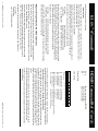
x^8 +x^6 +x^3 +x^2 + 1 = 101001101 = 14D hex
Ignore X^8:
01001101 = 4D hex
Reverse bit order:
10110010 = B2 hex
So:
The rest of the bits of the polynomial are reversed from the
polynomial's order. This allows us to read in each bit starting
with bit 0 of each byte, instead of bit 7. This is done because
the UART sends its LSB first and by doing the same we are able to
preserve the CRC's burst error detection characteristics.
To create the CRC8_POLY mask, we start by ignoring the highest
bit (x^8) since it is assumed to always be 1 and lies outside
our byte boundary, and doesn't affect our results.
Routine for updating the CRC-8 checkcode using a polynomial
of: x^8 +x^6 +x^3 +x^2 + 1.
#include "stdio.h"
The following is a simple “C” program that calculates the CRC-8 of the string “TestString” and
then prints the initial string with the calculated CRC-8 checkcode appended to it.
//
//
//
//
//
//
//
//
//
//
//
//
//
//
//
//
//
#define CRC8_POLY
#define CRC8_INIT
unsigned char
int
// get local copy of CRC-8
// test each bit against CRC-8
else
lcrc8 = (lcrc8 >> 1) & 0x7F;
}
*crc8 = lcrc8;
// return new CRC8
if (lcrc8 & 0x01)
lcrc8 = ((lcrc8 >> 1) & 0x7F) ^ CRC8_POLY;
// if resultant bit was a 1, shift and xor in mask
// else, just shift
for (bitcount = 0; bitcount < 8; bitcount++)
{
lcrc8 ^= cc;
// update CRC-8 with 8 new bits
lcrc8 = *crc8;
void crcByte( unsigned char *crc8, char cc)
{
// local copy of CRC-8 value
}
12 HDMI5 Component Video Switch
HDMI5 Command Ref. (Cont’d)
Where ‘mode’ settings are:
0 = Turn off front panel lights.
1 = Front panel lights are always at DIM level.
2 = Front panel lights are always at BRIGHT level.
3 = Front panel lights AUTODIM after 4 seconds.
The DIM and BRIGHT intensities range from 0=Off, to 106=Maximum brightness. You cannot set
the DIM level to be higher than or equal to the BRIGHT setting. Any attempt to do so will return
an ‘out of range’ error.
Save Power On Default Settings
Save current settings.
Restore all settings to their factory defaults.
Saves the current HDMI5 settings as the power on default settings.
S $
S 246,$
There is no Response String for this command.
Note: Any value given, other than ‘246’, will generate a range error.
Query Last IR Code Received
This command allows the controller to read the hash values returned by Zektor’s IIR™ (Intelligent Infra-Red) decoding firmware. Zektor’s IIR™ algorithm converts all IR codes it receives to
a compressed, 72 bit value.
Each different key press of a remote control will generate a different but repeatable pattern.
This command returns a value for every IR code detected by the front panel IR sensor (or IR
jack if enabled), regardless as to whether the IR code detected was used to control the HDMI5.
The uses for this command are two fold:
1) The value returned from this command are the same values used to teach the HDMI5 new IR
codes over the serial port. (See the “Set Learnable IR Command Codes” command).
2) This command gives the controller full access to the HDMI5’s IR sensor and Zektor’s IIR™
algorithm. This is a very reliable way of adding IR control to any project. The IR codes generated
by Zektor’s IIR™ algorithm are immune to timing differences between universal remote control
manufacturers and to the timing errors associated with condition of the remote control’s battery.
Note 1: The Zektor’s IIR™ algorithm works with any remote control code that is time modulated.
This is pretty much every type of IR code except the Phillips RC-5, and RC-6 codes.
Note 2: Because very few controllers could handle a 72 bit decimal value, and in an effort to
HDMI5 Component Video Switch 17
Set output to input ‘in’.
Sequence through inputs.
Query for current setting.
Query for current setting.
mode,dim,bright
mode,dim,bright,$
,dim
,,bright
?
= Current MODE setting.
= Current DIM level setting.
= Current BRIGHT level settings.
Set the MODE, DIM and BRIGHT levels.
Set the MODE, DIM and BRIGHT levels, backup settings.
Set only the DIM level.
Set only the BRIGHT level.
Query for current settings.
Query for current settings.
16 HDMI5 Component Video Switch
Where:
mode
dim
bright
=LI mode,dim,bright
Response String:
LI
LI
LI
LI
LI
LI
Set the dim and bright levels of the front panel LEDs. Some examples:
Front Panel Light Intensities
Where:
in = Current input being mapped to the HDMI5’s output.
=O in
Response String:
O in
O +
O ?
O
Maps the HDMI5’s output to a selected input.
Output Mapping
Where:
n = Current power status.
}
// initialize checkcode
HDMI5 Component Video Switch 13
printf( "%s%c%u", TestString, token, (unsigned char)crc8);
return (0);
// Print the results
crc8 = ~crc8;
// Finish with CRC8 by doing a one's compliment
crcByte( &crc8, token);
// Add the CRC-8 token character ':' to CRC-8
while (TestString[index] != 0)
crcByte( &crc8, TestString[index++]);
index = 0;
// CRC8 all of TestString[]
crc8 = CRC8_INIT;
TestString[] = "LI 2,3";
crc8;
index;
token = ':';
int main( void)
{
char
unsigned char
int
char
Response String:
=P n
Checksums and CRC-8’s (Cont’d)
HDMI5 Command Ref. (Cont’d)
HDMI5 Command Reference
The HDMI5 K.I.S.S.™ Command Reference
This section defines the K.I.S.S.™ commands that are available to the users of the HDMI5.
Error Response Codes
Unrecognized command.
A parameter was out of range.
Syntax error, badly formed command.
Checksum or CRC-8 error.
Too many or too few parameters.
System busy cannot process command.
Buffer overflow.
The following are the Error Response codes that can be returned by the HDMI5.
!1<CR><LF>
!2<CR><LF>
!3<CR><LF>
!4<CR><LF>
!5<CR><LF>
!6<CR><LF>
!7<CR><LF>
And some more detailed descriptions of their meanings:
Error 1: The command given was not recognized as a HDMI5 command. Commands are case
sensitive and in the HDMI5, all commands are upper case.
Error 2: One of the parameters given was too large, or too small, the command will be ignored.
Error 3: Something was wrong with the command's syntax. There was possibly extra data at the
end of the line, or non-decimal data as part of a parameter. There cannot be whitespace before
or after a checksum or CRC-8 checkcode, or this error will be returned.
Error 4: The ';' or ':' character was used to indicate a Checksum or CRC-8 Checkcode was
appended to the command string, but the Checksum or CRC-8 Checkcode did not match the
calculated one. The command will be ingnored.
Error 5: The number of parameters given does not match the number allowed by this command.
Error 6: To prevent conflicts between the front panel Setup Mode and the serial port settings,
when the HDMI5 is in the Setup Mode, many parameters become read only and any attempt at
writing them will return Error 6. The “Front Panel Button Emulation” command with button code
‘0’ can be used to exit the Setup Mode, at which point the command can be re-issued without an
Error 6 response.
Error 7: An internal buffer has overflowed, for instance more than 16 button codes were sent as
part of the “Front Panel Button Emulation” command.
The HDMI5 Command Set
Each command will be listed in all the different ways it can be issued. Usually each command
has two different ways of being issued. The first is used to set its value, the second as a query
command.
14 HDMI5 Component Video Switch
HDMI5 Command Ref. (Cont’d)
If the command has an associated response string, it will also be listed.
As described in the section on the K.I.S.S.™ protocol, whitespaces and commas are optional
in many cases. The format used here includes a single space after the command and commas, with no spaces, between parameters. The format given here does not show the optional
checksum or CRC-8 checkcodes that may be appended to all commands, nor does it show the
required <CR> that terminates all commands.
The response strings are the strings returned from HDMI5, which use the same format as
described above. The format does not show the optional checksum or CRC-8 checkcodes that
may be appended to all response strings if enabled, nor does it show the <CR><LF> that
terminates all Response Strings.
Version Query
Request version string.
Request version string.
Query for the current firmware version and PCB type of the HDMI5.
V ?
V
Response String:
=V HDMI5 firmware_ver (pcb_rev)
Where:
firmware_ver = Version number of the HDMI5’s firmware.
pcb_rev
= PCB Revision.
Power Control
0
1
+
?
Turn off power.
Turn on power.
Toggle power.
Query for current setting.
Query for current setting.
Turn on / off, or toggle the power state of the HDMI5.
P
P
P
P
P
HDMI5 Component Video Switch 15