1
MT-17E-003-D
STP-H600/H1000 Series
Turbomolecular Pump
INSTRUCTION MANUAL
(Third Edition-d)
Read through the Safety Precautions of this Manual
carefully before using the STP pump.
Keep this Manual in a place where you can quickly access
it at any time.
Seiko Instruments Inc.
Dec. 2001
Copyright 2001 Seiko Instruments Inc. All rights reserved. Printed in Japan.
STP-H600/H1000 Series Instruction Manual
SAFETY PRECAUTIONS
The Safety Precautions in this Manual constitute guidelines to protect operators, the STP pump
and its peripheral equipment.
To avoid personal injury and prevent product and/or peripheral equipment damage, observe the
Safety Precautions as well as the general safety rules (your country’s laws, regulations, safety
standards and so on).
If the equipment is used in a manner not specified by the Seiko Instruments, the protection
provided by the equipment may be impaired.
Symbols
◇ The following symbols are used in this manual:
WARNING
Death or Serious Personal Injury
Failure to follow the guidelines marked with this symbol may result in death or serious
personal injury.
CAUTION
Minor Personal Injury, Product and/or Peripheral equipment Damage
Failure to follow the guidelines marked with this symbol may result in minor personal
injury, product and/or peripheral equipment damage.
NOTICE
Items you must follow during operation and maintenance.
◇ Symbols as Marked on the Equipment
ATTENTION : refer to this manual.
Seiko Instruments cannot perfectly anticipate circumstances of all of hazards or problems. The
scope of anticipation is limited to the precautions included in the
CAUTION
specified in this manual.
1
WARNING
and
STP-H600/H1000 Series Instruction Manual
WARNING
◇ Check the properties of the gas to be used, referring to the Material Safety Data Sheet
(MSDS) you obtain from the gas supplier. Follow any and all safety precautions and/or
recommendations instructed by the gas supplier.
Take appropriate measures specified in the MSDS to prevent a problem if you use any
corrosive, reactive, flammable or other system gas. Dilute the pumped gas with a monitored
inert gas if necessary. Take appropriate measures so as not to cause a problem due to the
pumped gas
◇ The STP pump is provided with a high-speed rotor. Secure the STP pump according to the
specified method. Failure to do so may lead to serious personal injury, product and/or
peripheral equipment damage if any abnormality/error occurs in the rotor.
◇ The STP pump operates at high temperatures while the baking heater is in operation.
NEVER touch the STP pump and its peripheral equipment while the baking heater is in
operation.
Operators can burn hands.
◇ Always exhaust residual gases thoroughly from the STP pump when removing the STP
pump from the vacuum equipment. Residual gases in the STP pump may cause an
accident which, for certain gases, may involve serious injury or death.
Confirm the characteristics of the gas to be used, referring to the Material Safety Data Sheet
(MSDS) you obtain from the gas supplier. Wear personal protective equipment if
necessary.
◇ When covering the battery case, be sure not to catch the battery cable in the battery case.
Failure to do so may short-circuit the battery and result in a leakage, production of fire or
explosion.
◇ NEVER throw the battery into fire nor heat it.
Failure to do so may result in an explosion, production of fire and/or serious personal injury.
Observe the instructions given by the battery maker, the national and/or local government
when disposing of the battery.
◇ Exhaust residual gas thoroughly when disposing of the STP pump. If the STP pump is
used for any toxic or reactive gas, always clean the STP pump and dispose of it as industrial
waste in accordance with guidelines given by the national and/or local government.
Residual gas in the STP pump may cause an accident which, for certain gases, may involve
serious injury or death.
◇ Always remove the battery from the STP control unit when disposing of it. Failure to do so
may result in fire or other accident.
2
STP-H600/H1000 Series Instruction Manual
CAUTION
◇ NEVER use any gas that is not specified as usable in this Manual. The use of such gas
may corrode the STP pump and damage it.
◇ A hazardous live voltage may exist at connector/terminal that marked
.
DO NOT touch the terminal. Doing so may result in electric shock.
When operating connection/disconnection to terminal, always power OFF the STP pump
(Switch the breaker “OFF”).
◇ Always check the STP pump has stopped, then turn OFF the primary power (switch the
breaker “OFF”) before proceeding to any of the following operations. Failure to do so may
cause the STP pump to rotate accidentally, which may injure operators seriously or result in
electric shock.
·
Connect or disconnect cables;
·
Connect an external battery;
·
Perform maintenance and inspections such as replacement of the internal battery
and/or fuses as well as inspections of deposit and/or the air cooling fan (when replacing
fuses, always disconnect the internal battery connector);
·
Perform investigations into probable causes and action/measures taken in the event of
occurrence of a problem; or
·
Open and close the STP control unit front panel (hereinafter referred to as the front
panel) in order to check or reset the "BATTERY NG" (hereinafter referred to as
"BATTERY NG") lamp.
◇ The STP pump and the STP control unit are heavy products. Always use a crane or the
like when lifting them. When lifting the STP pump by hands for unavoidable reasons, it
must always be lifted by two or more people. Failure to do so may damage their hipbone or
injure them due to occurrence of an accident such as fall.
◇ Install the STP control unit not only by fitting it with the front panel fitting screws but also by
supporting it from the bottom side. Fitting the STP control unit with the screws only cannot
sustain its weight, and therefore resulting in product damage.
◇ Always use the STP pump, STP control unit and STP connection cables of the same model
name, serial number and cable length, which are specified on their own name plate.
Failure to do so may result in product damage. If you use units with the same model name
but different serial number and cable length; they must be adjusted. If the model names
are different, they may not be used even when performing adjustment. In both cases,
contact Seiko Instruments.
◇ Use the STP connection cable and the motor connection cable that have a label affixed
STP-H600/H1000
Series
.
The use of different cables may result in product damage.
◇ Connect the cables securely. NEVER bend nor place heavy objects on the cable. Doing
so may result in electric shock or product damage.
◇ Always use the power voltage specified on the name plate for the primary power voltage of
the STP control unit. Wire the power cable securely. Incorrect wiring may result in electric
shock or product damage.
◇ NEVER remove the splinter shield from the STP pump. Doing so may result in product
damage.
3
STP-H600/H1000 Series Instruction Manual
CAUTION
◇ DO NOT put foreign objects into the STP pump. Doing so may result in product damage.
◇ NEVER turn OFF the primary power (DO NOT switch the breaker “OFF”) while the STP
pump is rotating. Doing so may result in product damage.
◇ Perform investigations into probable causes and remove them before restarting the STP
pump in the event of occurrence of a problem. The use of the abnormal STP pump may
result in product damage.
◇ Always replace batteries once a year. Failure to do so, the battery backup operation may
not run at the power failure.
◇ DO NOT connect internal batteries and external batteries simultaneously. Failure to do so
may result in product damage.
◇ DO NOT move the STP pump and the STP control unit while the STP pump is in operation.
Doing so may result in product damage.
4
STP-H600/H1000 Series Instruction Manual
INTRODUCTION
Thank you very much for purchasing Seiko Instruments’s turbomolecular pump. The
turbomolecular pump is designed to be installed in the vacuum equipment in to exhaust
gases from it.
This manual covers all items necessary to ensure safe installation, operation and
maintenance of the following series of the STP-H600/H1000 turbomolecular pump:
·
·
·
·
Model Name
Specification
STP-H600
STP-H1000
STP-H600C
STP-H1000C
High-throughput type
High-throughput type
High-throughput type, chemical specific *1
High-throughput type, chemical specific
For the specifications of other models of the STP-H600/H1000 pump series, contact Seiko
Instruments.
In this manual, the above STP pump series is collectively referred to as the “STP pump.”
APPLIED STANDARDS
The STP pump conforms to the following directives and standards:
◇ Applied Directives
·
·
·
EC Machinery Directive
EC Electromagnetic Compatibility Directive
EC Low Voltage Directive
◇ Applied Standards
·
·
·
·
·
EN292-1
EN292-2
EN60204-1
EN55011 (class A)
EN50082-2
◇ Applied Standards (Only a some model)*2
·
*1
*2
UL3101-1,1993 (Electrical Equipment for Laboratory Use; Part 1 : General
Requirements)
Chemical specific: STP pump with anti-corrosive treatment (responding to chlorine, fluorine or other system gases)
Contact Seiko Instruments about recognized model.
5
STP-H600/H1000 Series Instruction Manual
PRECAUTIONS
1)
2)
No part of this manual may be reproduced in any form by any means
without prior
written permission from Seiko Instruments.
Seiko Instruments pursues a policy of continuing improvement in design and
performance of this product. The right is, therefore, reserved to vary specifications and
design without notice. Understand that the product you purchased and its contents
including specifications described in this manual may differ.
REQUEST
If you find inaccuracies or errors in this manual, advise your nearest sales representative
office of Seiko Instruments or the following sections of them:
Seiko Instruments Inc.
Sales Office (Japan)
Seiko Instruments Inc. Vacuum Innovative Products Sales Department
1-8 Nakase, Mihama-ku, Chiba-shi, Chiba 261-8507 JAPAN
Telephone:
<Vacuum Innovative Products Sales Department, Direct>
Domestic
043-211-1401
International
+ 81-43-211-1401
Facsimile:
Domestic
043-211-8075
International
+ 81-43-211-8075
Manufacturer, Sales Office (Japan)
Seiko Instruments Inc. Vacuum Innovative Products Division
4-3-1 Yashiki, Narashino-shi, Chiba 275-0004 JAPAN
Telephone:
<Vacuum Innovative Products Service Section, Direct>
Domestic
047-475-3123
International
+81-47-475-3123
<Company main>
Domestic
047-475-3111
International
+81-47-475-3111
Facsimile:
Domestic
047-471-1544
International
+81-47-471-1544
Copyright 2001 Seiko Instruments Inc. All rights reserved.
Vacuum Innovative Products Sales Department
1-8 Nakase, Mihama-ku, Chiba 261, Japan
Telephone:
+ 81-43-211-1401(Direct)
Facsimile:
+ 81-43-211-8075
6
STP-H600/H1000 Series Instruction Manual
LIMITED WARRANTY
This WARRANTY applies to the customer to whom Seiko Instruments has delivered this
product.
1. WARRANTY PERIOD:
Seiko Instruments warrants this product against defects for a period of
two (2) years from the date of delivery or during the period specified in
the agreement made by and between the customer and Seiko
Instruments.
2. ITEM WARRANTED:
1) This warranty applies only to the product delivered from Seiko
Instruments to the customer.
2) If any defect is found during this period, Seiko Instruments will, at
its option, repair or recondition the product free of charge. The
costs for repair or replacement of the product after the warranty
period has passed will be at the customer's own charge.
3. DISCLAIMER:
Seiko Instruments makes no warranty with respect to any damage occurred
due to any of the following during the warranty period:
1) Handling, operation or maintenance other than that specified herein;
2) Failure to follow any of the warnings or cautions enumerated under
or
3)
4)
5)
6)
7)
8)
9)
10)
11)
12)
13)
14)
15)
;
Installation, operation or maintenance using parts which are not
specified by Seiko Instruments;
Maintenance personnel other than those authorized by Seiko
Instruments or its specified plant have disassembled, reconditioned, or
tampered the product;
Defect resulting from the not-specified use of the product;
When the product is used under special conditions without obtaining
the written consent of Seiko Instruments (Particular gases, strong
magnetic field and the radiation are added to the product.);
Defect resulting from deposit;
Water cooling system defect resulting from water quality used;
Defect resulting from the installation of the product (Exclude the
installation by authorized personnel.);
Deterioration in the external because of use (Discoloration, scratches
and so forth);
Product damage occurred during transport or other factors not
attributable to Seiko Instruments;
Product breakage or damage due to natural disasters, fire or other
external factors;
Deterioration in the basic performance due to the use of the product
beyond limits of the use;
Any direct, incidental or consequential damage resulting from the use
of the product;
When continuously operated without overhaul after the WARNING
7
STP-H600/H1000 Series Instruction Manual
indication (“WARNING” message) on the LCD display;
16) Overhaul and replacement of maintenance parts;
4. SPARE PARTS:
● Fuse and air cooling fan for control unit
● Touch down bearing
● Heater
8
STP-H600/H1000 Series Instruction Manual
TABLE OF CONTENTS
SAFETY PRECAUTION
INTRODUCTION
LIMITED WARRANTY
1 Precautions for Safe Operation of the STP Pump ..................................... 1-1
1.1
1.2
1.3
1.4
Usable Gases............................................................................................................ 1-1
Maintenance Precautions.......................................................................................... 1-1
Inspection Precautions.............................................................................................. 1-2
Labels........................................................................................................................ 1-2
2 Unpacking .................................................................................................. 2-1
2.1
2.2
Unpacking the STP Pump......................................................................................... 2-1
Unpacking the STP Control Unit ............................................................................... 2-2
3 Installation of the STP pump...................................................................... 3-1
3.1
3.2
3.3
Name and Function of Each Part .............................................................................. 3-1
Precautions Before Installation ................................................................................. 3-3
3.2.1 Operating Environment ................................................................................ 3-3
3.2.2 Installation Area ........................................................................................... 3-4
3.2.3 Bench ........................................................................................................... 3-4
How to Install the STP Pump .................................................................................... 3-5
3.3.1 Cleaning the Seal ......................................................................................... 3-6
3.3.2 STP Pump Installation Positions .................................................................. 3-7
3.3.3 How to Secure the STP Pump ..................................................................... 3-8
3.3.4 Vacuum Piping ........................................................................................... 3-12
3.3.5 Connecting the Emergency Vent. Valve .................................................... 3-14
3.3.6 Connecting the Purge Port......................................................................... 3-14
3.3.7 Connecting the Ground Cable.................................................................... 3-15
4 Installation of the STP Control Unit............................................................ 4-1
4.1
4.2
4.3
4.4
Name and Function of Each Part .............................................................................. 4-1
4.1.1 Front Panel................................................................................................... 4-1
4.1.2 Rear Panel ................................................................................................... 4-4
4.1.3 Inside of the STP Control Unit...................................................................... 4-6
Precautions Before Installation ................................................................................. 4-8
4.2.1 Operating Environment ................................................................................ 4-8
4.2.2 Installation Area ........................................................................................... 4-9
Attaching the STP Control Unit Front Panel to a Rack ........................................... 4-10
Cable Connection.................................................................................................... 4-11
4.4.1 Name and Dimensions of Each Cable ....................................................... 4-11
4.4.2 How to Connect the Cables ....................................................................... 4-13
5 How to Start/Stop the STP Pump .............................................................. 5-1
5.1
5.2
5.3
5.4
5.5
Before Starting .......................................................................................................... 5-1
Starting/Stopping Time.............................................................................................. 5-1
Start Procedures ....................................................................................................... 5-2
Stop Procedures ....................................................................................................... 5-2
Manual Operation...................................................................................................... 5-3
5.5.1 Powering ON................................................................................................ 5-3
5.5.2 Starting the STP Pump ................................................................................ 5-3
5.5.3 Stopping the STP Pump............................................................................... 5-3
9
STP-H600/H1000 Series Instruction Manual
5.6
5.5.4 Starting the STP Pump after Stopping ......................................................... 5-3
5.5.5 Powering OFF .............................................................................................. 5-4
Remote Operation..................................................................................................... 5-5
5.6.1 Powering ON................................................................................................ 5-5
5.6.2 Starting/Stopping the STP Pump ................................................................. 5-5
5.6.3 Starting the STP Pump After Stopping......................................................... 5-5
5.6.4 Powering OFF .............................................................................................. 5-6
6 Safety Functions When an Abnormality/Error Occurs ............................... 6-1
6.1
6.2
6.3
Safety Functions........................................................................................................ 6-1
6.1.1 Power Failure ............................................................................................... 6-1
6.1.2 Abnormal State of Magnetic Bearing ........................................................... 6-3
6.1.3 Excessive Vibration...................................................................................... 6-3
6.1.4 Inverter Overload ......................................................................................... 6-3
6.1.5 Overheating Inside the STP pump ............................................................... 6-3
6.1.6 Overheating Inside the STP Control Unit ..................................................... 6-3
6.1.7 Overspeed.................................................................................................... 6-3
6.1.8 Abnormal Battery Voltage ............................................................................ 6-4
6.1.9 Failure of Brake............................................................................................ 6-4
Restarting after Any Safety Function Operates......................................................... 6-5
Operation of the Emergency Vent. Valve.................................................................. 6-7
7 Gas Suction, Cooling and Baking the STP Pump ...................................... 7-1
7.1
7.2
7.3
Gas Suction............................................................................................................... 7-1
7.1.1 How to Introduce a Purge Gas..................................................................... 7-1
Cooling the STP Pump.............................................................................................. 7-2
7.2.1 Water Cooling Method ................................................................................. 7-2
7.2.2 Air Cooling Method....................................................................................... 7-3
Baking the STP Pump............................................................................................... 7-4
7.3.1 Attaching a Baking Heater ........................................................................... 7-4
7.3.2 Interlocking the STP Pump Operation with Baking .......................................... 7-6
8 Remote Input/Output Signal Terminal Blocks ............................................ 8-1
8.1
8.2
8.3
8.4
I/O TB2 Terminal Block ............................................................................................. 8-1
DC I/O TB3 Terminal Block....................................................................................... 8-6
START STOP TB5 Terminal Block ........................................................................... 8-8
START/STOP TB6 Terminal Block ........................................................................... 8-9
9 Internal Battery........................................................................................... 9-1
9.1
9.2
9.3
9.4
9.5
9.6
Life of the Internal Battery ......................................................................................... 9-1
Allowable Shelf Life of the Internal Battery................................................................ 9-1
How to Charge the Internal Battery ........................................................................... 9-2
BATTERY NG Lamp ................................................................................................. 9-3
How to Replace the Internal Battery.......................................................................... 9-4
9.5.1 How to Replace the Battery Case ................................................................ 9-4
9.5.2 How to Replace the Battery in the Battery Case .......................................... 9-6
How to Dispose of the Internal Battery...................................................................... 9-8
10 External Battery ....................................................................................... 10-1
10.1
10.2
10.3
10.4
Specifications for the External Battery .................................................................... 10-1
Installation of the External Battery........................................................................... 10-2
How to Charge the External Battery........................................................................ 10-3
How to Dispose of the External Battery................................................................... 10-3
11 Operation Principle of the STP Pump ...................................................... 11-1
10
STP-H600/H1000 Series Instruction Manual
12 Maintenance and Inspection .................................................................... 12-1
12.1
12.2
12.3
12.4
12.5
12.6
Replacing the Internal Battery ................................................................................. 12-1
Inspecting the Air Cooling Fan ................................................................................ 12-1
Replacing the Fuses ............................................................................................... 12-2
Inspecting for Deposit ............................................................................................. 12-3
Overhaul.................................................................................................................. 12-4
Transporting for Repair or Overhaul ....................................................................... 12-5
13 Storage .................................................................................................... 13-1
13.1
13.2
13.3
The STP Pump........................................................................................................ 13-1
The STP Control Unit .............................................................................................. 13-2
Restarting Precautions............................................................................................ 13-2
14 Disposal ................................................................................................... 14-1
14.1
14.2
14.3
The STP Pump........................................................................................................ 14-1
The STP Control Unit .............................................................................................. 14-1
The Battery.............................................................................................................. 14-2
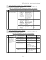
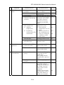
15 Troubleshooting ....................................................................................... 15-1
15.1
15.2
15.3
15.4
15.5
Troubleshooting Immediately After An Abnormality/Error Occurs .......................... 15-1
Abnormalities When Powering ON ......................................................................... 15-2
Abnormalities When Performing The STP Pump Start Operation.......................... 15-3
Abnormalities While the STP Pump is Rotating...................................................... 15-3
When Any Abnormality/Error Warning Lamp Lights ............................................... 15-5
16 Specifications and Accessories ............................................................... 16-1
16.1
16.2
16.3
16.4
Specifications for the STP Pump ............................................................................ 16-1
Specifications for the STP Control Unit................................................................... 16-2
Accessories............................................................................................................. 16-4
Recommended Spare Parts.................................................................................... 16-4
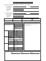
STP PUMP PROBLEM CHECK SHEET
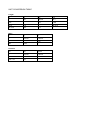
UNIT CONVERSION TABLE
11
STP-H600/H1000 Series Instruction Manual
TABLES
Table 3.1
Table 3.2
Table 3.3
Table 4.1
Table 5.1
Table 6.1
Table 6.2
Table 6.3
Table 7.1
Table 8.1
Table 8.2
Table 8.3
Table 8.4
Table 8.5
Table 8.6
Table 10.1
Table 15.1
Table 15.2
Table 15.3
Table 15.4
Table 15.5
Table 16.1
Table 16.2
Table 16.3
Table 16.4
Tightening torque of bolt ....................................................................................... 3-8
Maximum Torque predicted and
Recommended securing bolt for inlet port flange ................................................. 3-9
Number of Claw Clamps by Size of Flange ........................................................ 3-10
Connecting Primary Power Cable....................................................................... 4-15
Starting/Stopping the STP Pump During Remote Operation................................ 5-5
State of Lamps and REMOTE Output Signal at Power Failure ............................ 6-2
Operation of the STP Pump after Power Recovery .............................................. 6-2
Safety Functions ................................................................................................... 6-8
Attaching Positions of the Cooling Unit and Baking Heater .................................. 7-5
I/O TB2 Terminal Block ........................................................................................ 8-1
Rated Contacts for Relays CR1 to 4, CR7, CR8 and CR10 ................................. 8-4
Rated Contacts for Relays CR5 and 6.................................................................. 8-4
DC I/O TB3 Terminal Block .................................................................................. 8-6
START STOP TB5 Terminal Block....................................................................... 8-8
START/STOP TB6 Terminal Block....................................................................... 8-9
Specifications for the External Battery................................................................ 10-1
Troubleshooting After Powering ON ................................................................... 15-2
Troubleshooting When Performing The STP Pump Start Operation.................. 15-3
Troubleshooting While the STP Pump Is Rotating ............................................. 15-3
Cross Reference of Items of Abnormality Warning Lamps ................................ 15-5
Troubleshooting When Any of Abnormality/Error Warning
Lamp Lights ........................................................................................................ 15-6
Specifications for the STP Pump ........................................................................ 16-1
Specifications for the STP Control Unit .............................................................. 16-2
Accessories ........................................................................................................ 16-4
Recommended Spare Parts ............................................................................... 16-4
12
STP-H600/H1000 Series Instruction Manual
FIGURES
Figure 2.1
Figure 3.1
Figure 3.2
Figure 3.3
Figure 3.4
Figure 3.5
Figure 3.6
Figure 3.7
Figure 3.8
Figure 4.1
Figure 4.2
Figure 4.3
Figure 4.4
Figure 4.5
Figure 4.6
Figure 4.7
Figure 4.8
Figure 8.1
Figure 8.2
Figure 8.3
Figure 8.4
Figure 8.5
Figure 8.6
Figure 9.1
Figure 9.2
Figure 9.1
Figure 11.1
Figure 16.1
Figure 16.2
Figure 16.3
Figure 16.4
Figure 16.4
Example of Lifting the STP Pump......................................................................... 2-1
Configuration of the STP Pump ............................................................................ 3-2
Installation of the STP Pump to the Vacuum Equipment...................................... 3-5
STP Pump Installation Positions........................................................................... 3-7
Positions of the Outlet Port on the Horizontally or Slanted Installed STP Pump .. 3-7
Example of securing the STP pump (When securing the inlet port with bolts)..... 3-9
Example of securing the STP pump
(When securing the inlet port flange with claw clamps)...................................... 3-10
Example of securing the STP pump
(When installing the damper in the inlet port flange) .......................................... 3-11
Connecting the Purge Port and Emergency Vent. Valve .................................... 3-15
STP Control Unit Front Panel ............................................................................... 4-3
STP Control Unit Rear Panel ................................................................................ 4-5
Inside of the STP Control Unit .............................................................................. 4-7
Peripheral Space of the STP Control Unit ............................................................ 4-9
Example of Securing the STP Control Unit......................................................... 4-10
External Dimensions of Each Cable ................................................................... 4-11
External Dimensions of he Power Cable ............................................................ 4-12
How to Secure Primary Power Cable ................................................................. 4-16
I/O TB2 Remote Output Signal Terminal Block .................................................... 8-3
Example of Connecting I/O TB2 R. Pump Terminal ............................................. 8-5
Example of Securing the Remote Cable............................................................... 8-5
DC I/O TB3 Remote Input Signal Terminal Block................................................. 8-7
START STOP TB5 Remote Input Signal Terminal Block ..................................... 8-8
START/STOP TB6 Remote Input Signal Terminal Block ..................................... 8-9
Life of the Internal Battery..................................................................................... 9-2
Allowable Shelf Life of the Internal Battery ........................................................... 9-2
How to Replace the Internal Battery ..................................................................... 9-7
Cross Sectional View of the STP Pump ............................................................. 11-2
External Appearance of the STP Pump
(Example: STP-H1000 Series) ........................................................................... 16-5
External Appearance of the STP Control Unit .................................................... 16-6
Label Affixing Positions for the STP Pump ......................................................... 16-7
Label Affixing Positions for the STP Control Unit ............................................... 16-8
Label Affixing Positions for the Special Accessory ............................................. 16-9
13
STP-H600/H1000 Series Instruction Manual
1 Precautions for Safe Operation of the STP Pump
1.1
Usable Gases
Chlorine or fluorine system gases can be used in chemical specific pumps (STPH600C/H1000C or other models). When you use gases including alkaline metals, but
excluding Li, gases including Ga, Hg, In, or Sn, or HBr, contact Seiko Seiki.
WARNING
◇ Check the properties of the gas to be used, referring to the Material Safety Data
Sheet (MSDS) you obtain from the gas supplier. Follow any and all safety
precautions and/or recommendations instructed by the gas supplier.
Take appropriate measures specified in the MSDS to prevent a problem if you
use any corrosive, reactive, flammable or other system gas. Dilute the pumped
gas with a monitored inert gas if necessary. Take appropriate measures so as
not to cause a problem due to the pumped gas
CAUTION
◇ NEVER use corrosive gases (chlorine, fluorine, or other system gases) in the
STP-H600/STP-H1000 pump or other models without anti-corrosion treatment.
◇ Introduce a dry N2 gas (purge gas) to protect the inside of the STP pump when
using reactive or corrosive gases.
◇ Cool the STP pump to within the operating pressure range to prevent the STP
pump from overheating when sucking gases.
1.2
Maintenance Precautions
Perform any maintenance of the STP pump and the STP control unit (battery replacement,
fuse replacement), following Section 12, "Maintenance and Inspection".
CAUTION
◇ Always turn OFF the primary power (switch the breaker "OFF") before
performing any maintenance.
◇ Disconnect internal battery connector before performing maintenance of the STP
control unit.
◇ NEVER touch any portions other than those designated when performing
maintenance.
Careless touch may cause electric shock and/or a short-circuiting of the internal
circuit, resulting in product damage or a problem.
1-1
STP-H600/H1000 Series Instruction Manual
1.3
Inspection Precautions
Perform inspections of the STP pump and the STP control unit (check of the air cooling fan
and reset of the "BATTERY NG" lamp), following Section 12, "Maintenance and Inspection"
When performing inspections (check of the air cooling fan and reset of the "BATTERY NG"
lamp), always turn OFF the primary power (switch the breaker "OFF") before opening the
front panel, then turn ON the primary power again (switch the breaker "ON").
CAUTION
◇ NEVER touch any portions other than those designated when performing
inspections.
Careless touch may cause electric shock and/or a short-circuiting of the internal
circuit, resulting in product damage or a problem.
1.4
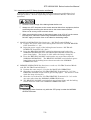
Labels
The following labels are affixed to the STP pump and STP control unit.
Read the contents of the labels before operation. For the positions of the labels, see Figures
“Label Affixing Positions”.
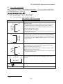
(1) STP Pump Caution Label
This label describes precautions for operating the STP pump.
Follow these precautions.
(2) STP Control Unit Caution Label
This label describes precautions for operating the STP control unit.
Follow these precautions.
1-2
STP-H600/H1000 Series Instruction Manual
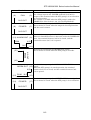
(3) Heavy Product Caution Label
This label is affixed to the product with a mass of 20 kg or more.
Follow the precautions of Section 2, "Unpacking" so as not to cause any accident during
handling.
(4) STP Pump Installation Warning Label
This label describes installation of the STP pump.
Install the STP pump according to the precautions of Section 3, "Installation of the STP
Pump. "
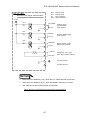
(5) Emergency Vent. Valve Caution Label
This label describes the emergency vent. valve installation position.
Connect the emergency vent. valve before use.
1-3
STP-H600/H1000 Series Instruction Manual
(6) Connector Caution Label
◇ This label describes lock of the connector.
◇ This label instructs operators to prevent the connectors from being disconnected while
the STP pump is in operation.
(7) STP Control Unit Safety Instruction Label
This label describes instructions before operating the STP control unit.
(8) High Voltage Device Caution Label
The STP control unit is equipped with a high voltage device.
pay attention to the high voltage device.
1-4
This label warns operators to
STP-H600/H1000 Series Instruction Manual
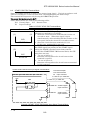
(9) Battery Instruction Label
This label instructs operators to replace batteries once a year.
The next replacement date of batteries is specified upon delivery of the STP pump.
Record the next replacement date (after one year) of batteries in the blank of the label when
replacing them.
This label describes precautions for use of external batteries.
(10) Rotational Direction Instruction Label
This label describes the rotational direction of the STP pump.
The STP pump rotates in this direction.
ROTATION
(11) Voltage Rating Label
This label describes the rated voltage of the STP control unit.
Use voltage specified in this label.
200∼240V
1-5
STP-H600/H1000 Series Instruction Manual
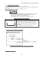
(12) Hot Surface Warning Label
This label instructs operators so as not to touch the hot surface of the STP pump.
The use of the baking heater (optional accessory) may lead to a considerable rise in
temperatures outside the STP pump.
This label warns operators so as not to burn hands.
(only when using the baking heater.)
(13) Tuning Caution Label
This label describes precautions for performing the tuning.
Tuning should be performed by Seiko Seiki trained or authorized personnel only.
! 注意
浮上調整を行う場合は弊社
のトレーニングまたは許可を
受けてください。
! CAUTION
Tuning must be performed
by Seiko Instruments Inc. or
authorized personnel only.
1-6
STP-H600/H1000 Series Instruction Manual
2 Unpacking
2.1
Unpacking the STP Pump
Check the following before unpacking the STP pump.
1) Check the package for bruises, breakage, wetness, etc.
If there is any abnormality/error or it is judged necessary to return the product, contact
Seiko Seiki.
2) Check the contents of the package.
See Section 16.3, "Accessories."
CAUTION
◇ The mass of the STP pump is approx. 30 kg. Use a crane or other appropriate
means to lift the STP pump.
Lift the STP pump with an eyebolt or a similar tool that uses the fitting hole
attached to the inlet port flange.
Lift it with the aid of a suspension tool under the base when installing the STP
pump without fitting hole.
◇ Observe national laws/regulations, safety standards and so on when lifting the
STP pump.
◇ Use a crane or other appropriate means sufficient enough to withstand the load
when lifting the STP pump.
◇ Always lift the STP pump in stable places free of excessive shock or vibration to
prevent it from shaking or dropping.
◇ Have at least two people lift the STP pump when doing so by hand.
NOTICE
◇ Be careful not to scratch the flange of the STP pump.
Before installing the STP pump, check whether or not there are scratches on the
surface.
◇ It is recommended to keep the packaging materials, such as the corrugated
fiberboard container and cushioning material for possible reuse.
Figure 2.1 Example of Lifting the STP Pump
2-1
STP-H600/H1000 Series Instruction Manual
2.2
Unpacking the STP Control Unit
Check the following before unpacking the STP control unit.
1) Check the package for bruises, breakage, wetness, etc.
If there is any abnormality/error or it is judged necessary to return the product, contact
Seiko Seiki.
2) Check the contents of the package.
See Section 16.3, "Accessories."
CAUTION
◇ The mass of the STP control unit is approx. 40 kg. Use a crane or appropriate
means to lift the STP control unit.
Lift the STP control unit using the two handles attached to the front panel.
◇ Observe national laws/regulations, safety standards and so on when lifting the
STP control unit.
◇ Use a crane or appropriate means sufficient enough to withstand the load when
lifting the STP control unit.
◇ Always lift the STP control unit in stable places free of excessive shock or
vibration to prevent it from shaking or dropping.
◇ Have at least two people lift the STP control unit when doing so by hand.
NOTICE
◇ It is recommended to keep the packaging materials, such as the corrugated
fiberboard container and cushioning material for possible reuse.
2-2
STP-H600/H1000 Series Instruction Manual
3 Installation of the STP pump
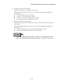
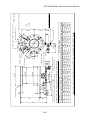
3.1
Name and Function of Each Part
(1) Inlet Port Flange (ICF*1 , VG*2 , ASA, ISO, etc.)
l Connected to the vacuum equipment (at the high vacuum side).
CAUTION
◇ A splinter shield is attached to the inlet port flange to prevent foreign particles
from falling into the STP pump.
NEVER remove it.
(2) Outlet Port Flange (KF*2 40)
l Connected to the inlet port side of the auxiliary pump.
(3) STP Connector (41 pins)
l Connected to the STP connection cable.
(4) Motor Connector (5 pins)
l Connected to the motor connection cable.
(5) Purge Port (KF*2 10)
l Introduces a purge gas.
In order to protect the inside of the STP pump when sucking reactive or
corrosive gases.
The STP pump is delivered with a blank flange attached to this port.
(6) Cooling Water Port (PT*2 (R/C)1/4 Female Screw)
l Connected to the STP pump cooling water pipe.
This port is used when water cooling the STP pump.
(7) Emergency Vent. Valve
l Protects the STP pump.
It functions immediately after any abnormality/error occurs inside the STP
pump.
(8) Ground Terminal
l Used for grounding.
Connect the ground cable between this terminal and the ground terminal of the
STP control unit .
The ground terminal is marked with label
.
(9) Temperature Sensor Connector (optional accessory)
l A temperature sensor is attached.
For use with the Temperature Management System (TMS) unit only.
*1
*2
:
:
JVIS
JIS
3-1
STP-H600/H1000 Series Instruction Manual
(1) Inlet Port Flange
(9) Temperature Sensor
Connector
Optional Accessory
(2) Outlet Port Flange
(6) Cooling Water Port
( 6) Cooling Water Port
(3) STP Connector
(4) Motor Connector
(8) Ground Terminal
(7) Emergency Vent . Valve
(5) Purge Port
Figure 3.1 Configuration of the STP Pump
3-2
STP-H600/H1000 Series Instruction Manual
3.2
Precautions Before Installation
3.2.1 Operating Environment
CAUTION
◇ Chlorine or fluorine system gases can be used in chemical specific pumps (type
C). When you use gases including alkaline metals, but excluding Li, gases
including Ga, Hg, Sn, or HBr, contact Seiko Instruments.
◇ NEVER use corrosive gases (chlorine, fluorine, or other system gases) in the
STP-H600/STP-H1000 pump or other models without anti-corrosion treatment
(see Section 1.1, "Usable Gases").
Install the STP pump in a place meeting the following requirements:
Ambient Temperature
0 to 40 °C
Ambient Relative Humidity
30 to 95 % (no dew condensing)
Environment
l A place free of externally-applied mechanical shock.
l A place free of a heat source
(Keep clean of the heat source or attach a thermal
shield plate).
l A place free of a strong magnetic field
(Range: up to 15mT (150G) in the axial direction,
and up to 3mT (30G) in the radial direction with
respect to the rotational axis of the STP pump).
l A place free of a strong electric field.
l A place free of exposure to radiation.
l No discharge of high voltage (more than 500 V)
(If more than 500 V is discharged, contact Seiko
Instruments).
STP Pump Installation
l Install the STP pump securely so that foreign
Equipment Conditions
particles will easily fall into the STP pump (Ex.: Si
wafers or samples are positioned above the STP
pump) (To prevent foreign particles from falling into
the STP pump, design a shield plate with large
conductance).
3-3
STP-H600/H1000 Series Instruction Manual
3.2.2 Installation Area
Leave enough space for the following in addition to that for the STP pump:
·
Space for maintenance and inspection
·
Space for connecting cables
◇ The minimum bending radius of the STP connection cable is 150 mm (see
Figure 16.1, "External Appearance of the STP Pump" [bending dimensions of
the STP connection cable]).
DO NOT excessively bend the cables and beware of any obstacles when
installing the STP pump.
Also, leave enough space to install other cables without bending them
excessively.
3.2.3 Bench
A bench must be prepared by the customer to secure the STP pump. The shape
and size of the bench differ depending upon the type of STP pump. Follow the
precautions of the WARNING, CAUTION, or NOTICE (See Section 3.3.3, "How to
Secure the STP Pump").
◇ The STP pump is provided with a high-speed rotor. Any internal
abnormality/error may result in a jump in rotational torque leading to personal
injury or peripheral equipment damage.
Design and secure the bench for the STP pump so that it can withstand the
maximum torque generated due to the occurrence of an abnormality/error.
Refer to Section 3.3.3 “How to Secure the STP Pump” for abnormal torque.
◇ Secure the customer-prepared bench and the vacuum equipment on the floor or
peripheral equipment and other equipment in accordance with the customer
application. NEVER move them while the STP pump is in operation.
Use fitting bolts with a strength equal to or higher than SUS 304*1 . (Tensile
strength class*1: 50 or more as a target)
◇ The screw hole for leg for securing the STP pump is M12*1, and the depth is
24mm (8 positions).
For the external appearance of the STP pump, see Figure 16.1, "External
Appearance of the STP Pump."
*1
:JIS
3-4
STP-H600/H1000 Series Instruction Manual
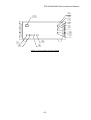
3.3
How to Install the STP Pump
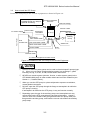
Install the STP pump to the vacuum equipment as shown in Figure 3.2.
The STP pump can be
installed through the damper
(optional accessory).
Vacuum Equipment
Inlet Port
Inlet Port Flange
Vacuum Valve
Front Panel
To Power Supply
Power Cable
Emergency
Vent.Valve
STP Pump
Dry Pump,etc.
Auxiliary
Pump
Emergency
Vent. Valve Cable
STP
Control Unit
STP Connection Cable
Outlet Port
Motor Connection Cable
Leg
Ground Cable
Remote Cable
To Vacuum Equipment Control Circuit
Figure 3.2 Installation of the STP Pump to the Vacuum Equipment
CAUTION
◇ Chlorine or fluorine system gases can be used in chemical specific pumps (type
C). When you use gases including alkaline metals, but excluding Li, gases
including Ga, Hg, In, or Sn, or HBr, contact Seiko Instruments.
◇ NEVER use corrosive gases (chlorine, fluorine, or other system gases) in the
STP-H600/H1000 pump or other models without anti-corrosion treatment (see
Section 1.1, "Usable Gases").
◇ When you use the STP pump in a place subjected to exposure to radiation,
contact Seiko Instruments.
◇ DO NOT open the STP pump through the flange to atmospheric air while the
STP pump is running.
If atmospheric air flows into the STP pump, it may not function normally.
◇ Depending upon the type of the auxiliary pump used, atmospheric air may
reverse flow into the STP pump when the auxiliary pump stops. Attach a
vacuum valve to the middle of the piping between the STP pump outlet port
flange and the auxiliary pump, and close the vacuum valve when the auxiliary
pump stops.
3-5
STP-H600/H1000 Series Instruction Manual
NOTICE
◇ The STP pump cannot be used with the outlet port open to atmospheric air.
Always use the auxiliary pump (dry pump or similar one).
◇ Use an auxiliary pump with a pumping speed of 240 L/min or more.
◇ Depending upon the type of the auxiliary pump used, oil vapor may contaminate
the inside of the STP pump. Some oil viscosity could cause a malfunction
when there is a strong reverse flow of oil.
Take the following measures to ensure the correct flow of oil:
·
·
Attach a vacuum valve to the middle of the piping between the STP pump
outlet port flange and the auxiliary pump.
Attach an absorption trap adjacent to the vacuum valve.
3.3.1 Cleaning the Seal
Inspect the seals of inlet and outlet port flanges for dirt or oil spots before installing
the STP pump in the vacuum equipment.
Take the following measures for cleaning the seals:
·
Clean off with a pure gas.
·
Wipe with proper solvent (such as alcohol).
CAUTION
◇ A splinter shield is attached to the inlet port flange to prevent foreign particles
from falling into the STP pump.
Always leave the splinter shield attached during operation.
NOTICE
◇ The splinter shield cannot perfectly prevent foreign materials from falling into the
STP pump.
DO NOT install the STP pump in such a manner that foreign materials can
easily fall into it (for example, Si wafers or samples are positioned above the
STP pump). If installing the STP pump in such a manner, always attach a
shield plate with sufficient conductance above the STP pump to prevent foreign
materials from falling into it. Foreign materials falling into the STP pump
through the splinter shield may result in product damage.
◇ Be careful not to scratch the flange of the STP pump.
Check whether or not there are scratches on the surface, before installing the
STP pump.
3-6
STP-H600/H1000 Series Instruction Manual
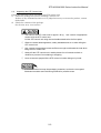
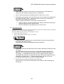
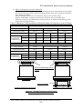
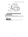
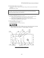
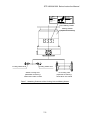
3.3.2 STP Pump Installation Positions
The STP pump can be installed vertically, horizontally, upside-down and slanted.
Upside-down
Horizontal
STP Pump
Slanted
Vertical
Figure 3.3 STP Pump Installation Positions
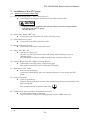
When installing the STP pump in a horizontal or slanted position, it is
recommended to install it so that the direction of the outlet port is on a vertical or
horizontal plane in the direction of the gravity.
This makes it possible to reduce the load on the magnetic bearing and the heat
generated by the STP pump.
Outlet Port
Outlet Port
Outlet Port
Outlet Port
Direction of Gravity
Figure 3.4 Positions of the Outlet Port on the Horizontally or Slanted Installed STP Pump
3-7
STP-H600/H1000 Series Instruction Manual
3.3.3 How to Secure the STP Pump
◇ The STP pump is provided with a high-speed rotor. The worst-case failure may
result in a jump in rotational torque leading to personal injury or peripheral
equipment damage.
The method of securing the STP pump will depend on the installation
requirements. Secure the STP pump to the vacuum equipment as follows:
◇ Design and secure the mounting for the STP pump so that it can withstand the
maximum rotational torque. Refer to Table 3.2 for torque in pump abnormality.
with bolts
Refer to “1) When securing the
inlet port with bolts”
No
Secure the inlet port
Damper
with Claw Clamps
Refer to “2) When securing the
inlet port flange with claw
clamps”
Refer to “3) When installing the
damper in the inlet port flange”
Yes
◇ In some cases, the damper and the claw clamper securing cannot be used
depend on the type of the STP pump.
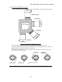
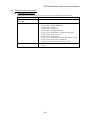
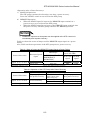
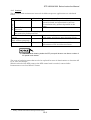
◇ Refer to Table 3.1 for tightening torque of the bolt.
Table 3.1
Tightening torque of bolt
Size of bolt
Tightening torque of bolt (Nm)
M8
M10
M12
12.0
24.1
42.1
◇ When making the leg to secure the base, make them shortened more than ones
attached to the STP pump.
Use a material that has a tensile strength of 600N/mm2 or more.
◇ When securing the base, use stainless steel securing bolts with a tensile
strength class is 70 or more.
◇ When using any securing method other than that specified in this manual,
contact Seiko Instruments.
3-8
STP-H600/H1000 Series Instruction Manual
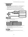
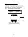
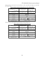
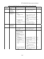
1)
When securing the inlet port with bolts
Refer to Table 3.2 for torque in pump abnormality and recommended securing bolts.
Secure the inlet port flange with all of the boltholes of the size specified in the Inlet
Port Flange Standard.
Secure the base with all 8 screw-holes for legs or all 8 attached legs.
Follow “CAUTION” on page 3-8 about legs and bolts for securing the base.
Make sure that the recommended securing bolt may be different depending on the
method of securing the base.
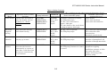
Table 3.2 Maximum Torque predicted and Recommended securing bolt for inlet port flange
Model of TMP
STP-H600
Type of flange
Torque in pump
abnormality [Nm]
Base(8 positions)securing
Recommended
securing bolt
for TMP Flange
VG150
ISO160F/ISO160
ICF203
2.2×10⁴
2.2×10⁴
2.2×10⁴
No
Yes
No
Yes
Type of bolt
Standard
Type of steel*1
Carbon steel
Alloyed steel
Strength*1
12.9 or more
Standard
Standard
Stainless steel
Carbon steel
Alloyed steel
70 or more
12.9 or more
Model of TMP
No
Yes
Standard
Standard
Standard
Stainless steel
Carbon steel
Alloyed steel
Stainless steel
70 or more
12.9 or more
70 or more
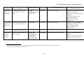
STP-H1000
Type of flange
Torque in pump
abnormality [Nm]
VG200
ISO200F/ISO250F/ISO200
ICF253
1.9×10⁴
1.9×10⁴
2.2×10⁴
Base(8 positions)securing
No
Recommended Type of bolt
securing bolt Type of steel*1
for TMP Flange
*1
Standard
Standard
Stainless steel
Stainless steel
70 or more
70 or more
Strength
Yes
No
Yes
Standard
Standard
Stainless steel Stainless steel
70 or more
70 or more
No
Yes
Standard
Standard
Stainless steel Stainless steel
70 or more
70 or more
Recommended fitting bolt for
flange
Secure the base
(a) When the base is not secured
(b) When the base is secured
Figure 3.5 Example of securing the STP pump
(When securing the inlet port with bolts)
*1 Refer to ISO898-1(JISB1051), ISO3506(JISB1054) and AMS6119(Aerospace Material Specification)
3-9
STP-H600/H1000 Series Instruction Manual
2)
When securing the inlet port flange with claw clamps
Refer to Table 3.2 for rotational torque.
When securing the inlet port flange with only the claw clamp, the vacuum
equipment cannot withstand the maximum rotational torque generated by the
worst-case failure. To make the vacuum equipment withstand abnormal torque,
secure the base with all 8 screw-holes for legs or all 8 attached legs.
Follow “CAUTION” on page 3-8 about legs and bolts for securing the base.
For the claw clamp-type, use the required number of claw clamps as specified in
Table 3.3. Position the claw clamps evenly on the circumference.
Table 3.3
Number of Claw Clamps by Size of Flange
Size of Flange
ISO 160 or less
ISO 200 to 250
ISO 320 or more
Number of Claw Clamps
4 or more
6 or more
8 or more
Vacuum Equipment
Claw Clamps
Secure the base
Figure 3.6 Example of securing the STP pump
(When securing the inlet port flange with claw clamps)
3-10
STP-H600/H1000 Series Instruction Manual
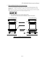
3)
When installing the damper in the inlet port flange
Refer to Table 3.2 for rotational torque.
In case of using a damper, secure the base with all 8 screw-holes for legs or all 8
attached legs. Follow “CAUTION” on page 3-8 about legs and bolts for securing
the base.
When the base cannot be secured because of the equipment design, install the pump
with a torque restraint like the one shown in Figure 3.7 (b).
◇ Use a damper only at the vertically upright position.
◇ DO NOT remove the bolts and nuts attached to reinforce the damper.
Vacuum Equipment
Vacuum Equipment
Damper Clamps
Secure the base
Hole to prevent
from rotating
Leg
(a) When securing the base
(b) When installing not to rotate
Figure 3.7 Example of securing the STP pump
(When installing the damper in the inlet port flange)
3-11
STP-H600/H1000 Series Instruction Manual
3.3.4 Vacuum Piping
◇ DO NOT open the STP pump through the flange to atmospheric air while the
STP pump is running.
If atmospheric air flows into the STP pump, it may not function normally.
◇ Depending upon the type of the auxiliary pump used, atmospheric air may
reverse flow into the STP pump when the auxiliary pump stops.
Attach a vacuum valve to the middle of the piping between the STP pump outlet
port flange and the auxiliary pump, and close the vacuum valve when the
auxiliary pump stops.
In order to let the STP pump bring its performance into full play, follow the
precautions below:
1) Be careful not to scratch the flange of the STP pump.
Before installing the STP pump, check whether or not there are scratches on
the surface.
2) Use steel or aluminum tubes with a low gas loss to connect the vacuum
equipment to the STP pump.
3) Take measures for minimizing leakage. It is also necessary to degrease the
tubes as regularly as possible to keep the gas loss as low as possible.
4) It is recommended to use an auxiliary pump of 240 L/min or more. However,
the pressure at the inlet and outlet ports varies with the flow rate of gas,
capacity of the vacuum equipment, length and material of the piping. Select
an auxiliary pump in accordance with the capacity and starting method
(simultaneous starting, starting after generating roughing vacuum) suitable for
the vacuum equipment you use.
5) Connect the STP pump and the auxiliary pump using stainless steel or
aluminum alloy tubing, flexible tubing, vacuum rubber or Teflon tubing, etc.
The following measures can be used to avoid the transmission of the vibration
of the auxiliary pump to the STP pump and the vacuum equipment.
·
DO NOT place the auxiliary pump on the same floor as the vacuum
equipment.
·
Locate the auxiliary pump on a vibration-proof table.
·
Attain 1/3 or less of the rotational speed of the auxiliary pump,
when
adjusting the inherent frequency of the auxiliary pump installed on a
vibration-proof table.
·
Attach a weight to the piping from the auxiliary pump, or secure the piping
to a rigid, heavy object free of vibration.
·
Use a tube of high flexibility.
6) Depending upon the type of the auxiliary pump used, oil vapor may
contaminate the inside of the STP pump. Some oil viscosity could cause a
malfunction when there is a strong reverse flow of oil.
Take the following measures to ensure the correct flow of oil:
·
Attach a vacuum valve to the middle of the piping between the STP pump
outlet port flange and the auxiliary pump.
·
Attach an absorption trap adjacent to the vacuum valve.
3-12
STP-H600/H1000 Series Instruction Manual
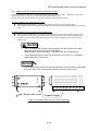
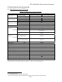
(1) Piping at the Inlet Port Flange
Attach the inlet port to the high vacuum side.
Maximum working pressure (Pressure at the inlet port flange applicable
continuously)
l 67 Pa [0.5 Torr] (for water cooled)
l 5.3 Pa [4×10⁻² Torr] (for air cooled)
l 0.9 Pa [7×10⁻³ Torr] (for natural air cooled)
l 13 Pa [0.1 Torr] (when TMS unit is used)
(2) Piping at the Outlet Port Flange
Attach the outlet port to the inlet port flange of the auxiliary pump (primary
side pump).
Allowable backing pressure (Pressure at the outlet port flange applicable
continuously)
l 400 Pa [3 Torr] (for water cooled, when TMS unit is used)
l 267 Pa [2 Torr](for air cooled, natural air cooled)
◇ To attain the ultimate pressure shown in Table 16.1, "Specifications for STP
Pump", set the pressure at the outlet port flange to 1.3 Pa (10-2 Torr) or less.
3-13
STP-H600/H1000 Series Instruction Manual
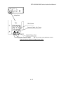
3.3.5 Connecting the Emergency Vent. Valve
The emergency vent. valve stops the STP pump by introducing gases if any
abnormality/error occurs in the STP pump.
Connect the emergency vent. valve (contained in the attached accessories) to the
purge port as shown in Figure 3.7. Note that the side of the emergency vent. valve
without filter is connected to the purge port.
Connect the cable for the emergency vent. valve to the connector, LEAK VALVE
CON8A, of the STP control unit.
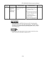
◇ Always attach the emergency vent. valve.
◇ DO NOT close the port of the emergency vent. valve (filter side) with a blank
flange or other type of device.
◇ The allowable gas pressure ranges from zero [atmospheric pressure] to
4.9x10⁴Pa [gauge pressure] (zero [atmospheric pressure] to 0.5kgf/cm2 [gauge
pressure]).
◇ Use a dry N2 gas or other.
3.3.6 Connecting the Purge Port
When sucking reactive or corrosive gases, introduce a dry N2 gas or other gas into
the STP pump in order to protect the inside of the STP pump.
As shown in Figure 3.7, introduce a dry N2 gas through the electromagnetic vent.
valve, needle valve or similar valve (must be prepared by the customer) from the
purge port.
For instructions on how to introduce the purge gas, See Section 7.1, "Gas Suction."
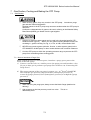
◇ The proper amount of gas purge is approx. 3.4×10⁻² Pa·m3/s (20 SCCM).
◇ The allowable gas pressure ranges from zero [atmospheric pressure] to
4.9x10⁴Pa [gauge pressure] (zero [atmospheric pressure] to 0.5kgf/cm2 [gauge
pressure]).
◇ When not introducing the purge gas, close the purge port with the blank flange
(attached at delivery).
3-14
STP-H600/H1000 Series Instruction Manual
Dry N2 Gas or Other
Filter Side
Emergency Vent. Valve
KF10
Dry N2 Gas or Other
Purge Port
Figure 3.8 Connecting the Purge Port and Emergency Vent. Valve
3.3.7 Connecting the Ground Cable
Connect the ground cable (yellow/green) between the ground terminal of the STP
pump and the ground terminal of the STP control unit.
When the resistance between the ground terminals is lower than 0.1 W, it is not
necessary to connect the ground cable after installing the STP pump and the STP
control unit.
◇ When the resistance between the ground terminals is over 0.1 W, always
connect the ground cable.
3-15
STP-H600/H1000 Series Instruction Manual
4 Installation of the STP Control Unit
4.1
Name and Function of Each Part
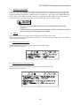
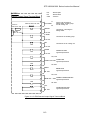
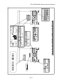
4.1.1 Front Panel
(1) "POWER ON/OFF" Switch (illuminated alternate push button switch, green
LED)
l Press this switch to power ON/OFF the STP pump (MANUAL operation
only).
l The POWER ON/OFF built-in lamp lights when the power is ON.
(2) "MOTOR START" Switch (momentary push button switch, black)
l Press this switch with power ON to rotate and accelerate the STP pump
(MANUAL operation only).
l The "ACCELERATION" lamp lights simultaneously.
(3) "MOTOR STOP" Switch (momentary push button switch, red)
l Press this switch to decelerate and stop the STP pump (MANUAL
operation only).
l The "NORMAL OPERATION" lamp or the "ACCELERATION" lamp goes
out and the "BRAKE" lamp lights simultaneously.
When the rotational speed is less than approx. 2000 rpm while the STP
pump is accelerating, the "BRAKE" lamp does not light.
(4) "HEATING ON/OFF" Switch (illuminated alternate push button switch, green
LED)
l Press this switch to control the power supplied to the baking (MANUAL
operation only).
l While the power is being supplied to the baking heater, the "HEATING
ON/OFF" switch built-in lamp lights.
l Functions only under the NORMAL OPERATION state (for details, see
Section 8, "Remote Input/Output Signal Terminal Blocks").
(5) "NORMAL OPERATION" Lamp (green LED)
l Lights during rated operation (NORMAL OPERATION state).
(6) "ACCELERATION" Lamp (green LED)
l Lights during acceleration (ACCELERATION state).
(7) "BRAKE" Lamp (yellow LED)
l Lights during braking (BRAKE state).
4-1
STP-H600/H1000 Series Instruction Manual
(8) "OVER TEMPERATURE" Lamp (red LED)
l Lights when any of the following abnormalities occurs:
a) When the motor or electromagnet overheats (110 ℃ or higher).
b) When the STP connection cable is not connected.
(9) "BATTERY OPERATION" Lamp (red LED)
l Lights while the power is being supplied from the battery to the STP pump
during a power failure.
(10) "FAILURE" Lamp (red LED)
l Lights when any of the following abnormalities occurs:
a) When the inside of the STP control unit overheats (90 ℃ or more
inside the heat sink).
b) When the motor or electromagnet overheats (110 ℃ or more).
c) When an abnormality occurs inside the inverter (overload, overspeed).
d) When the battery is thoroughly worn out and cannot be charged.
e) When the STP connection cable is not connected.
(11) "EMERGENCY OPERATION" Lamp (red LED)
l Lights when any of the following abnormalities occurs:
a) When a power failure occurs.
b) When continuous vibration impact is applied to the rotor causing it to
come into contact with the touch down bearing.
c) When the STP connection cable is not connected.
For details concerning lamps (8) to (11) and abnormalities, see Section 6, "Safety
Functions When an Abnormality/Error Occurs" and Section 15, "Troubleshooting."
(12) ROTATION Meter (tachometer)
l Indicates the rotational speed (rpm).
l The needle moves to the black with an increase in rpm.
l The needle moves to the red with a decrease in rpm.
l The needle is located in the black during the rated operation.
4-2
STP-H600/H1000 Series Instruction Manual
(5)
(6)
(12)
(7)
(8)
(9)
(10)
(11)
(1)
(2)
(4)
(3)
Figure 4.1 STP Control Unit Front Panel
4-3
STP-H600/H1000 Series Instruction Manual
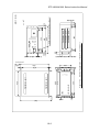
4.1.2 Rear Panel
CAUTION
◇ A hazardous live voltage may exist at connector/terminal that marked
.
DO NOT touch the terminal. Doing so may result in electric shock.
When operating connection/disconnection to terminal, always power OFF the
STP pump (Switch the breaker "OFF").
(13) AC POWER Terminal Block (TB1)
A maximum voltage : Equal to the input voltage of this terminal block. (MAX
240VAC)
l For primary power input.
(14) MAIN POWER Breaker
l Switches ON/OFF the primary power.
l A metal fitting is attached to secure the breaker at the OFF position.
(15) P. CONNECTOR (CON5A)
A maximum voltage : 60VDC
l For connection of the STP connection cable.
(16) INVERTER OUTPUT Connector (CON2)
A maximum voltage : 55VDC
l For connection of the motor connection cable.
(17) LEAK VALVE Connector (CON8A)
A maximum voltage : 60VDC
l For connection of the emergency vent. valve cable.
(18) Ground Terminal
l For connection of the ground cable between the STP pump and the STP
control unit.
(19) I/O TB2 Terminal Block
A maximum voltage : Equal to the input voltage of this terminal block. (MAX
250VAC)
l For remote control.
(20) DC I/O TB3 Terminal Block
A maximum voltage : 12VDC
l For remote control.
(21) START STOP TB5 Terminal Block
A maximum voltage : 12VDC
l For remote control.
4-4
STP-H600/H1000 Series Instruction Manual
(22) START/STOP TB6 Terminal Block
A maximum voltage : Equal to the input voltage of this terminal block. (MAX
250VAC)
l For remote control.
For details concerning remote control terminal blocks (19) to (22), see Section 8,
"Remote Input/Output Signal Terminal Blocks."
(23) "MANUAL/REMOTE" Changeover Switch
l When setting to MANUAL, only start, stop or other operations can be
performed with the switches on the STP control front panel.
l When setting to REMOTE, only start, stop or other operations can be
performed by inputting the remote signal.
(24) EXT. BATTERY (CON9) Connector
A maximum voltage : 55VDC
l For connection of an external battery.
CAUTION
◇ When using EXT. BATTERY (CON9) connector, always disconnect the internal
battery connector (see Section 10, "External Battery" for details).
(21)
(14)
(13) (15)
(18)
(23)
(17) (20)
(22)
(24)
(19)
Figure 4.2 STP Control Unit Rear Panel
4-5
(16)
STP-H600/H1000 Series Instruction Manual
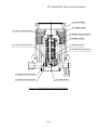
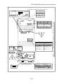
4.1.3 Inside of the STP Control Unit
(25) Inverter
l This is a three-phase transistor-inverter which starts/stops the STP pump.
(26) Fuses 3 to 9, 11, and 12
l These fuses protect as follows:
F3 and 4: 250 V, 5 A (for control power protection)
F5 to 7 : 250 V, 10 A, arc-extinguishing fuses
(for I/O TB2 terminal block power optional drive protection)
F8 and 9: 250 V, 10 A, arc-extinguishing fuses
(for internal and external batteries protection)
F11 and 12: 250 V, 0.1 A (for START/STOP TB6 terminal block protection)
(27) Control Circuit Boards
l For control of the magnetic bearing, motor, safety functions, etc.
(28) Internal Battery
l For backup during a power failure.
(29) Internal Battery Connector
l For connection of internal battery (when using an internal battery, connect
it to this connector).
l The internal battery has been installed upon shipment of the STP control
unit so that the customer can use it (the internal battery connector is
connected to the internal battery).
CAUTION
◇ When using an external battery, disconnect internal battery connector, then
connect external battery connector (see Section 10, "External Battery" for
details).
(30) Air Cooling Fan
l For cooling the inside of the STP control unit.
(31) "BATTERY NG" Lamp
l Lights when the battery capacity reduces to the minimum level (see
Section 9.4, "BATTERY NG Lamp”).
(32) "Reset" Switch
l Resets the state of inability to start the STP control unit due to a decrease
in the battery capacity (see Section 9.4, "BATTERY NG Lamp”).
4-6
STP-H600/H1000 Series Instruction Manual
(25)
(30)
(26)
(27)
(28)
(29)
(30)
(32)
(31)
Figure 4.3 Inside of the STP Control Unit
4-7
STP-H600/H1000 Series Instruction Manual
4.2
Precautions Before Installation
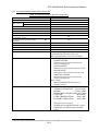
4.2.1 Operating Environment
Install the STP control unit in a place meeting the following requirements:
Ambient Temperature
0 ℃ to 40 ℃
Ambient Relative
30 to 95% (no dew condensing)
Humidity
Environment
l A place free of exposure to direct sunlight.
l A place free of high humidity.
l A place free of dust.
l A place free of salty air.
l A place free of dripping water.
l A place free of explosive or inflammable gas.
l A place free of corrosive gas.
l A place free of radiation.
l A place free of strong magnetic and electric fields.
l A place free of excessive vibration.
l A place free of a source of electric noise.
Installation Condition
l Install the STP control unit horizontally (within
±10°).
4-8
STP-H600/H1000 Series Instruction Manual
4.2.2 Installation Area
Leave enough space for the following in addition to that for the STP control unit.
·
·
·
Space for maintenance and inspection
Space for inlet and outlet of air for cooling
- Top and side:
5 cm or more
- Bottom:
2.4 cm or more (height of the rubber foot)
Space for connecting the cables
- Rear:
15 cm or more
CAUTION
◇ The minimum bending radius of the STP connection cable is150 mm (see
Rack Wall Side
5 cm or more
Figure 16.2, "External Appearance of the STP Control Unit" [Cable Space]).
DO NOT excessively bend the cables and beware of any obstacles when
installing the STP pump.
Also, leave enough space to install other cables without bending them
excessively.
Rack Wall Side
Ventilation Port
Ventilation Port
5 cm or more 5 cm or more
2.4 cm or more
Ventilation Port
5 cm or more 15 cm or more
Figure 4.4 Peripheral Space of the STP Control Unit
4-9
STP-H600/H1000 Series Instruction Manual
4.3
Attaching the STP Control Unit Front Panel to a Rack
The dimensions of the STP control unit front panel conform to JIS. Therefore, this panel
can be attached to any type of commercially-available racks.
Attach the front panel unit to the rack according to the following steps:
1) When attaching the front panel to a rack:
l Attach the front panel to a rack using the screw holes for the front panel.
l Also support the STP control unit from the bottom using a support angle or a similar
tool.
2) When attaching the front panel to a movable rack:
l Attach the front panel to a movable rack using the screw holes for the front panel.
l To protect the STP control unit during transport, remove the rubber foot from the
bottom and attach the STP control unit to the rack using the screw holes for the
rubber foot.
CAUTION
◇ The STP control unit cannot be supported with only the screws on the front
panel (the STP control unit is a heavy product).
Always support it from the bottom. DO NOT block the ventilation port.
◇ For the peripheral space of the STP control unit, see Figure 4.4, "Peripheral
Space of the STP Control Unit."
NOTICE
◇ For the dimensions of the front panel and positions of screw holes for the rubber
foot, see Figure 16.2, "External Appearance of the STP Control Unit."
part: Secure with screw
Support Angle
Figure 4.5 Example of Securing the STP Control Unit
4-10
STP-H600/H1000 Series Instruction Manual
4.4
Cable Connection
4.4.1 Name and Dimensions of Each Cable
STP Control Unit Side
Ground Terminal (
STP Pump Side
)
Ground Terminal (
*1
Ground Cable
Crimp-Type Terminal Lug (M4 )
Yellow / Green Wire
L≦20m : 4mm2
L>20m : 10mm2
)
*1
Crimp-Type Terminal Lug (M4 )
φ4.3(L≦20m)
φ6.5(L>20m)
Unit: mm
45 Pin (pin)
41 Pin (socket)
φ 40
STP-H600/H1000
Series
76.5
φ17
STP Connection Cable
24.5
STP-H600/H 1000
Series
φ30
5 Pin (socket)
STP-H600/H1000
Series
φ30
5 Pin (pin)
φ 8.1
Motor Connection Cable
Unit: mm
8 Pin (pin)
φ6.8
Emergency Vent. valve
φ22
Emergency Vent.
Valve Cable
Unit: mm
Unit: mm
Figure 4.6 External Dimensions of Each Cable
*1
:
JIS
4-11
STP-H600/H1000 Series Instruction Manual
Power Side
STP Control Unit Side
*1
9.8
Power Cable
Crimp-Type Terminal Lug (M4 )
2.5mm2×3core (brown, blue, yellow/green)
(a) without the Power Plug
Power Side
STP Control Unit Side
Plug type
*1
Crimp-Type Terminal Lug (M4 )
72.3
NEMA L6-30
Y(N[L2])
blue
φ 54
9.8
Power Cable
3pin (pin)
2.5mm2×3core
(brown, blue, yellow/green)
G(GND[ ])
yellow/green
(b) with the Power Plug*2
Figure 4.7 External Dimensions of he Power Cable
*1
: JIS
*2
: Recognized model to UL3101-1 standard has power cable with the plug.
4-12
X(L[L1])
brown
STP-H600/H1000 Series Instruction Manual
4.4.2 How to Connect the Cables
CAUTION
◇ When connecting/disconnecting cables, always power OFF the STP pump
(switch the breaker "OFF").
Failure to do so may result in electric shock or product damage.
◇ With each connector, align the position of the guide key and insert the pin
vertically so as not to bend it.
If the pin is bent, not only may the connector not function normally, but may the
pin make contact, resulting in a malfunction.
◇ Lock and securely tighten each connector and screw.
◇ DO NOT apply voltage to each pin and DO NOT cause any short-circuiting
between pins.
◇ Connect each cable securely. DO NOT place heavy objects on the cables nor
bend them excessively.
Support each cable so as not to apply direct force to the connectors or terminals.
If any problem occurs in cables, connectors or terminals, the STP pump may not
function normally.
1)
Connecting Ground Cable
Connect the ground cable (yellow/green) between the ground terminal of the
STP pump and the ground terminal of the STP control unit.
When the resistance between the ground terminals is lower than 0.1 W, it is not
necessary to connect the ground cable after installing the STP pump and the
STP control unit.
CAUTION
◇ First, connect the ground cable. Next, connect other cables.
◇ When the resistance between the ground terminals is over 0.1 W, always
connect the ground cable. Failure to do so may result in electric shock.
4-13
STP-H600/H1000 Series Instruction Manual
2)
Connecting the STP Connection Cable
Connect the socket side of the STP connection cable to the STP connector of the
STP pump and connect the pin side to "P.CONNECTOR CON5A" of the STP
control unit.
CAUTION
◇ Always use the STP pump, STP control unit and the STP connection cables of
the same model name, serial number and cable length. Failure to do so may
result in product damage.
Contact your nearest Seiko Seiki representative if you plan to use units with the
same model name but different serial numbers and cable length; They must
be adjusted. In some cases, the configuration may need more adjustment.
◇ Use the STP connection cable that has a label affixed
STP-H600/H1000
Series
The use of different cables may result in product damage.
3)
Connecting the Motor Connection Cable
Connect the socket side of the motor connection cable to the motor connector of
the STP pump and connect the pin side to "INVERTER OUTPUT CON2" of the
STP control unit.
CAUTION
◇ Use the motor connection cable that has a label affixed
STP-H600/H1000
Series
The use of different cables may result in product damage.
4)
Connecting the Emergency Vent. Valve Cable
Connect the emergency vent. valve to the purge port of the STP pump and the
connector to "LEAK VALVE CON8A" of the STP control unit (see Section 3.3.5,
"Connecting the Emergency Vent. Valve").
4-14
STP-H600/H1000 Series Instruction Manual
5)
Connecting Primary Power (Primary Side) Cable
Connect power cable to the "AC POWER TB1" on the STP control unit rear
panel as shown in Table 4.1.
Table 4.1 Connecting Primary Power Cable
TB1 Pin No.
Cable Color
Remarks
1 [L(L1)]
Brown
Single phase 200 to 240 V AC ±10%
13A (maximum)
2 [N(L2)]
Blue
Both 50/60 Hz
Yellow/Green
Ground
3 [PE(
)]
Secure primary power cable to the STP control unit rear panel using the cable
fitting tool (see Figure 4.7).
CAUTION
◇ Connect the primary power cable securely to prevent incorrect wiring.
◇ DO NOT apply surge voltage exceeding 1 kV to the input power line.
◇ Always ground primary power cable to prevent electric shock.
◇ DO NOT remove the ground cable attached to the terminal block cover.
4-15
STP-H600/H1000 Series Instruction Manual
Magnified
TB1
TB1 Cover
Ground Cable for Cover
Cable Fitting Tool
Primary Power Cable
part: Secure using attached screws
Figure 4.8 How to Secure Primary Power Cable
4-16
STP-H600/H1000 Series Instruction Manual
5 How to Start/Stop the STP Pump
CAUTION
◇ NEVER connect or disconnect any cables while the power is ON.
◇ NEVER turn the primary power OFF (switch the breaker "OFF") while the STP
pump is in rotation.
◇ DO NOT release the inlet port flange or outlet port flange into the atmosphere
while the STP pump is in rotation.
5.1
Before Starting
After completing installation, piping, leakage test of the STP pump and installation of the
STP control unit, the STP pump is ready for start.
Check the following items before starting:
1) Are the STP pump and the STP control unit secured according to the appropriate
method?
2) Is the primary power cable connected correctly to the power supply?
3) Is the power voltage selected properly?
4) Do the manufacturing No. and the cable length of the STP pump, the STP control unit
and the STP connection cable match?
5) Are the labels affixed correctly to the STP connection cable and the motor connection
cable?
STP-H600/H1000
Series
6)
5.2
Are the ground cable, the STP connection cable, the motor connection cable, and the
emergency vent. valve cable securely connected?
Is the connection cable securely connected?
Are each terminal and each connector securely locked?
Starting/Stopping Time
Starting time:
Stopping time:
Approx. 6 minutes after start operation.
Approx. 6 minutes after stop operation.
If the rotational speed does not attain the rated speed within about 15 minutes, the
"FAILURE" lamp lights. Before restarting the STP pump, always check whether or not
there is leakage from the piping or the vacuum equipment and also confirm the capacity and
the START state of the auxiliary pump.
NOTICE
◇ When start/stop operations are frequently performed, the STP pump may
overheat. Avoid doing so.
5-1
STP-H600/H1000 Series Instruction Manual
5.3
Start Procedures
Start the auxiliary pump before or simultaneously with start of the STP pump.
Open the vacuum valve located at the outlet port flange side after starting the auxiliary
pump.
NOTICE
◇ DO NOT open the vacuum valve without operating the auxiliary pump.
Doing so may cause a reverse flow of oil, which could contaminate the inside of
the STP pump.
5.4
Stop Procedures
Close the vacuum valve located at the outlet port flange side just before or after stopping the
STP pump.
After closing the valve, stop the auxiliary pump.
CAUTION
◇ DO NOT stop the auxiliary pump without closing the vacuum valve. Depending
upon the type of the auxiliary pump, doing so could cause a reverse flow of
atmospheric air into the STP pump, which may result in a malfunction.
NOTICE
◇ DO NOT stop the auxiliary pump without closing the valve.
Doing so may cause a reverse flow of oil, which could contaminate the inside of
the STP pump.
5-2
STP-H600/H1000 Series Instruction Manual
There are two methods of operating the STP pump: MANUAL and
REMOTE.
Select one which fits your vacuum equipment.
5.5
Manual Operation
Slide the "MANUAL/REMOTE" changeover switch on the rear panel to "MANUAL."
5.5.1 Powering ON
1)
2)
Switch ON the breaker on the rear panel (to prevent incorrect operation, a
metal fitting is attached to the breaker. Loosen the screw, lift the metal
fitting and secure it).
Press the "POWER ON/OFF" switch (the switch is thoroughly locked down).
The magnetic bearing functions and the rotor levitates (POWER ON state).
The "POWER ON/OFF" switch built-in lamp lights.
5.5.2 Starting the STP Pump
1)
2)
Press the "MOTOR START" switch on the front panel after powering ON to
start and accelerate the STP pump.
The "ACCELERATION" lamp lights (ACCELERATION state).
When the STP pump attains the rated speed of rotations, the
"ACCELERATION" lamp goes out, and the "NORMAL OPERATION" lamp
lights (NORMAL OPERATION state).
5.5.3 Stopping the STP Pump
1)
2)
Press the "MOTOR STOP" switch on the front panel to stop the STP pump.
The STP pump starts to decelerate and stop.
The "NORMAL OPERATION" lamp or the "ACCELERATION" lamp goes out,
and the "BRAKE" lamp lights (BRAKE state)
(when the rotational speed is less than approx. 2000 rpm while the STP pump
is accelerating, the "BRAKE" lamp does not light).
The "BRAKE" lamp goes out when the rotational speed slows down to approx.
1000 rpm.
5.5.4 Starting the STP Pump after Stopping
Press the "MOTOR START" switch on the front panel to reaccelerate the STP
pump.
5-3
STP-H600/H1000 Series Instruction Manual
5.5.5 Powering OFF
1)
When all of the "ACCELERATION," "NORMAL OPERATION" and "BRAKE"
lamps are off:
Press the "POWER ON/OFF" switch. The switch pops up into the unlocked
position, the magnetic bearing stops, and the rotor lands (POWER OFF state).
The "POWER ON/OFF" switch built-in lamp goes out.
2)
When one of the "ACCELERATION," "NORMAL OPERATION" and "BRAKE"
lamps is lit:
i. Even when the "POWER ON/OFF" switch is OFF, the rotor will not land.
Also, operation of the STP pump remains unchanged.
The "POWER ON/OFF" switch built-in lamp remains lit.
ii. When the STP pump stops under the above state, the magnetic bearing
stops, and the rotor automatically lands at the time the "BRAKE" lamp
goes out.
NOTICE
◇ The brake of the STP pump disengages at approx. 1000 rpm and the "BRAKE"
lamp goes out. The STP pump rotates by inertia even after the "BRAKE" lamp
has gone out.
Powering OFF immediately after the "BRAKE" lamp goes out or while any lamp
of the “ACCELERATION," "NORMAL OPERATION," or "BRAKE" lamp is being
lit causes the touch down bearing to touch the rotor resulting in a noise.
Frequent POWER OFF operations will expedite the wear of the touch down
bearing. It is recommended to power OFF the STP pump after it stops
thoroughly.
5-4
STP-H600/H1000 Series Instruction Manual
5.6
Remote Operation
Slide the "MANUAL/REMOTE" changeover switch on the STP control unit rear panel to
"REMOTE."
5.6.1 Powering ON
Switch ON the breaker on the STP control unit rear panel,
(to prevent incorrect operation, a metal fitting is attached to the breaker. Loosen
the screw, lift the metal fitting and secure it ).
The magnetic bearing functions and the rotor levitates (POWER ON state).
The "POWER ON/OFF" switch built-in lamp lights.
5.6.2 Starting/Stopping the STP Pump
There are three methods of starting/stopping the STP pump. Use one of them.
Table 5.1 Starting/Stopping the STP Pump During Remote Operation
1
Terminal
Block
TB5
2
TB5
3
TB6
Method
Starting the Pump
1)
Short the circuit between (3) (2) (STOP IN).
2) Short the circuit between (2) (1) (START IN) for 0.3 seconds
or more.
However, when inputting the
signal simultaneously with
switching ON the breaker on
the rear panel, continue to
short the circuit for 5 seconds
or more.
Short the circuit between (1) - (3)
(START/STOP IN).
Stopping the Pump
Open the circuit
between (3) - (2) (STOP
IN).
Open the circuit
between (3) - (1)
(START/STOP IN).
Input 25 to 250 V AC or 24 to 48 V Open the circuit
DC between (2) - (1) (START/STOP between (2) - (1)
(START/STOP IN).
IN).
With DC, the (+) side can be
connected to either (2) or (1).
5.6.3 Starting the STP Pump After Stopping
Perform the rotation procedures to reaccelerate the STP pump. See Section 5.6.2,
"Starting/Stopping the STP Pump."
The STP pump can be reaccelerated even while the STP pump is stopping.
5-5
STP-H600/H1000 Series Instruction Manual
5.6.4 Powering OFF
When all three ("ACCELERATION", "NORMAL OPERATION" and "BRAKE")
lamps are off, switch the breaker OFF on the rear panel.
The magnetic bearing stops, and the rotor lands.
The POWER ON/OFF switch built-in lamp goes out.
CAUTION
◇ NEVER switch OFF the breaker on the rear panel while any of the
"ACCELERATION," "NORMAL OPERATION" and "BRAKE" lamps is being lit.
If doing so under the above condition, the STP pump may react as if there was a
power failure.
NOTICE
◇ The brake of the STP pump disengages at approx. 1000 rpm and the "BRAKE"
lamp goes out. The STP pump rotates by inertia even after the "BRAKE" lamp
has gone out.
Powering OFF immediately after the "BRAKE" lamp goes out causes the touch
down bearing to touch the rotor resulting in a noise.
Frequent POWER OFF operations may expedite the wear of the touch down
bearing. It is recommended to power OFF the STP pump after it stops
thoroughly.
5-6
STP-H600/H1000 Series Instruction Manual
6 Safety Functions When an Abnormality/Error Occurs
The STP pump is provided with safety functions for various abnormalities/errors (See Tables
6.3 and 6.4, "Safety Functions").
For troubleshooting, see Section 6.2, "Restarting After Any Safely Function Operates" and
Section 15, "Troubleshooting."
6.1
Safety Functions
6.1.1 Power Failure
<Operation at a Power Failure>
When power voltage drops below 170 V due to a power failure, internal battery of
the STP control unit automatically activate to supply power to the STP pump in
order to maintain normal function of the magnetic bearing (backup operation
during a power failure).
1)
The STP control unit detects any power failure of 2 seconds or more and
automatically switches to the BATTERY OPERATION mode and the STP
pump decelerates. Gases are introduced from the emergency vent. valve at
approx. 7000 rpm and the rotor lands on the touch down bearing and stops at
approx. 2000 rpm.
In the BATTERY OPERATION mode, the "BATTERY OPERATION" lamp and
the "EMERGENCY OPERATION" lamp light, and an alarm signal is output
from I/O TB2 ALARM OUT terminals (10) – (9), (10) – (11) regardless of
MANUAL or REMOTE OPERATION mode.
When the rotor lands on the touch down bearing, the "BATTERY
OPERATION" lamp and the "EMERGENCY OPERATION" lamp go out, and
the alarm output is reset.
2)
In case of a power failure of less than 2 seconds, the STP control unit does not
detect it and the STP pump continues rotating.
6-1
STP-H600/H1000 Series Instruction Manual
<Operation after a Power Recovery>
1) MANUAL Operation
The STP pump continues decelerating even after a power recovery.
Press the "START" switch to reaccelerate the STP pump.
2)
REMOTE Operation
·
When the START signal is input to the REMOTE input terminal at a
power recovery to reaccelerate the STP pump.
·
When the START signal is not input to the REMOTE input terminal after
the power recovery, the STP pump continues the BRAKE operation.
NOTICE
◇ Establish a sequence so that power can be supplied to the STP control unit
immediately after a power recovery.
Table 6.1 shows the states of lamps and the REMOTE output signal at a power
failure.
Also, Table 6.2 shows operations of the STP pump after a power recovery.
Table 6.1 State of Lamps and REMOTE Output Signal at Power Failure
LED lamps
REMOTE output
signal (I/O TB2)
Rotational speed
“BATTERY OPERATION”
(rpm)
Power ON
“EMERGENCY
signal
OPERATION”
Less than 2000
Lights
ON
Approx. 2 sec. or more
2000 or less
Goes out
OFF
Less than approx. 2 sec.
Does not detect power failure.
Power failure time
ALARM
signal
ON
OFF
Table 6.2 Operation of the STP Pump after Power Recovery
MANUAL operation
REMOTE operation
STP pump operation
STP pump operation “START” REMOTE
Power failure time
after power recovery
after power recovery signal input after
power recovery
Yes
Reacceleration
Approx. 2 sec. or more Deceleration/Stop
No
Deceleration/Stop
Less than approx. 2 sec.
Continues as before.
6-2
STP-H600/H1000 Series Instruction Manual
6.1.2 Abnormal State of Magnetic Bearing
When the magnetic bearing does not function normally due to a breakage of the
STP connection cable, disconnection of connectors or any abnormality/error of the
STP control circuit, the rotor falls on the touch down bearing.
Simultaneously, the emergency vent. valve is opened to introduce gases and the
STP pump stops, and the "EMERGENCY OPERATION" lamp lights.
CAUTION
◇ When an abnormality/error occurs in the magnetic bearing, check the STP
pump as well as the STP control unit, and contact Seiko Seiki.
6.1.3 Excessive Vibration
When serious vibration or mechanical shock causes the rotor to touch the touch
down bearing (due to external vibration/impact, intrusion of atmosphere or foreign
materials into the STP pump or rotor imbalance), the emergency vent. valve is
opened to introduce gases, the STP pump stops, and the "EMERGENCY
OPERATION" lamp lights.
6.1.4 Inverter Overload
When the STP pump does not attain the rated speed within about 15 minutes after
starting or when the ACCELERATION state remains unchanged during operation
for about 15 minutes, the inverter stops and the STP pump continues rotating by
inertia.
The "FAILURE" lamp lights.
6.1.5 Overheating Inside the STP pump
When the temperature of the motor inside the STP pump exceeds 110 ℃ due to an
abnormal baking temperature or overload operation, the STP pump enters the
STOP operation.
The "OVER TEMPERATURE" lamp and the "FAILURE" lamp light.
6.1.6 Overheating Inside the STP Control Unit
When the temperature inside the STP control unit (at the heat sink) exceeds 90 ℃
due to a failure in the air cooling fan, external heat source, etc., the STP pump
enters the STOP operation.
The "FAILURE" lamp lights.
6.1.7 Overspeed
When the rotational speed of the STP pump exceeds 37,500 rpm due to a failure in
the inverter, the STP pump enters the STOP operation.
The "FAILURE" lamp lights.
6-3
STP-H600/H1000 Series Instruction Manual
6.1.8 Abnormal Battery Voltage
When battery capacity became less than operating limit value or there was
connection mistake, there may be the thing that battery abnormality is detected.
When battery abnormality was detected, the STP pump does not operate even if the
STP pump START operation is performed.
The "FAILURE" lamp lights
(Both the "EMERGENCY OPERATION" lamp and the "BATTERY NG" lamp inside
the STP control unit front panel may light).
When battery voltage became less than DC21V, battery abnormal detection
operates.
However, when capacity of battery is less than operating limit value largely, there
may be the thing that battery abnormal detection does not operate.
CAUTION
◇ NEVER disconnect the internal or external battery connection cable while the
STP pump is under POWER ON state.
NOTICE
◇ When the "BATTERY NG" lamp inside the STP pump front panel comes on,
"FAILURE" and "EMERGENCY OPERATION" lamps also come on.
When the power is turned on again, the "FAILURE" lamp goes out, while the
"BATTERY NG" and “EMERGENCY OPERATION" lamps still remain lit.
6.1.9 Failure of Brake
If the brake is broken, the emergency vent. valve is opened to force the STP pump to
stop.
6-4
STP-H600/H1000 Series Instruction Manual
6.2
Restarting after Any Safety Function Operates
1)
In case of a power failure:
Establish a sequence so that power can be supplied to the STP control unit immediately
after a power recovery.
2)
In case the "FAILURE" lamp lights due to an overload of the inverter
(the STP pump continues rotating by inertia: [FREE RUN state]):
<MANUAL OPERATION>
(1) Press the "MOTOR STOP" switch. The "FAILURE" lamp goes out and the FREE RUN
state is reset.
(2) Press the "MOTOR START" switch and press the "MOTOR STOP" switch again. The
brake functions and the STP pump decelerates.
(3) After the STP pump stops thoroughly (the "BRAKE" lamp goes out: the needle of the
tachometer is in the red), turn "OFF" the "POWER ON/OFF" switch, switch the breaker
"OFF," and remove probable causes of the abnormality/error.
(4) Restart the STP pump and check if it operates correctly.
<REMOTE OPERATION>
(1) Slide the "MANUAL/REMOTE" changeover switch on the rear panel to “MANUAL.”
(2) Press the "MOTOR STOP" switch. The "FAILURE" lamp goes out and the FREE RUN
state is reset.
(3) Press the "MOTOR START" switch and press the "MOTOR STOP" switch again. The
brake functions and the STP pump decelerates.
(4) After the STP pump stops thoroughly (the "BRAKE" lamp goes out: the needle of the
tachometer is in the red) , switch the breaker "OFF," and remove probable causes of the
abnormality/error.
(5) Restart the STP pump and check if it operates correctly.
<In case the FREE RUN state is not reset after troubleshooting:>
(1) Check the tachometer on the front panel.
(2) If the needle is in the red, it means the STP pump has stopped.
Power OFF and switch the breaker "OFF."
(3) If the needle is in the black, the STP pump is rotating.
Wait for it to enter the red. Then, power OFF and switch the breaker "OFF."
(4) Restart the STP pump and check if operates correctly.
CAUTION
◇ DO NOT power OFF and switch the breaker OFF until the needle is in the red.
NOTICE
◇ If the FREE RUN state cannot be reset, it takes about 8 to 10 hours to stop the
STP pump (the needle is in the red) because it rotates by inertia.
To stop the STP pump quickly, close the vacuum valve at the outlet port flange
and introduce gas from the purge port into the STP pump.
6-5
STP-H600/H1000 Series Instruction Manual
3)
Other Cases
After the STP pump stops thoroughly, power OFF, switch the breaker "OFF" and
remove the cause of the abnormality/error. Then, restart the STP pump and check if it
operates correctly.
NOTICE
◇ For probable causes and troubleshooting, See Section 15, "Troubleshooting."
6-6
STP-H600/H1000 Series Instruction Manual
6.3
Operation of the Emergency Vent. Valve
The emergency vent. valve is opened immediately after an abnormality/error in the
magnetic bearing, excessive vibration or any other abnormality/error is found. Gases (dry
N2 gases or other) are introduced through the emergency vent. valve into the STP pump.
Attach the emergency vent. valve taking care of the following NOTICE:
NOTICE
◇ It is recommended to introduce dry N2 gases to prevent the STP pump and
vacuum equipment from getting contaminated.
◇ The allowable gas pressure ranges from zero [atmospheric pressure] to
4.9x10⁴Pa [gauge pressure] (zero [atmospheric pressure] to 0.5kgf/cm2 [gauge
pressure]).
◇ The rotor comes into contact with the touch down bearing, with the emergency
vent. valve opened. This may damage the rotor or the touch down bearing.
To stop the STP pump in a very short time, design an appropriate vacuum
exhaust system that closes the vacuum valve at the outlet port flange when the
emergency vent. valve is opened.
This prevents the rotor and the touch down bearing from being damaged.
◇ The state of the emergency vent. valve can be checked using "DC I/O TB3 L.
VALVE N. O. OUT Terminal (9)-(10)."
6-7
STP-H600/H1000 Series Instruction Manual
Table 6.3 Safety Functions
Abnormality
/Error
Operation state of safety
functions
Power failure Failure time: 2 seconds or
more (for details, refer to
Section 6.1.1, "Power
Failure").
Lamp indication
REMOTE
output signal
[E.V. used herein is the abbreviation for Emergency Vent.]
Probable causes of an
State of the STP pump
abnormality/error
"BATTERY
OPERATION"
"EMERGENCY
OPERATION"
"ALARM"
"E.V. valve
OPEN
signal"
Power failure.
Levitation continues by battery.
Power cable breakage.
The STP pump stops.
Power cable disconnection
The E.V. valve functions at
approx. 7000 rpm.
The rotor lands on the touch down
bearing at approx. 2000 rpm.
Abnormal
magnetic
bearing
Rotor descends onto the
touch down bearing.
"EMERGENCY
OPERATION"
"ALARM"
"E.V. valve
OPEN
signal"
The E.V. valve is opened.
The STP pump stops.
STP connection cable breakage.
STP connection cable
disconnection.
Abnormal control circuit.
Excessive
vibration
Rotor vibration:
100 mm p-p or more.
"EMERGENCY
OPERATION"
"ALARM"
"E.V. valve
OPEN
signal"
The E.V. valve is opened.
The STP pump stops.
External vibration, and impact.
Intrusion of atmospheric air.
Intrusion of foreign materials.
Overload of
inverter
Current of more than 40A
flows into the inverter
momentarily or current of
more than 11.5A flows into
the inverter continuously
for 15 minutes.
"FAILURE"
"ALARM"
Leakage from the vacuum
The inverter stops.
The STP pump continues to rotate equipment or piping.
by inertia.
Insufficient pressure at inlet
and outlet port sides.
Failure of starting of the
auxiliary pump.
6-8
STP-H600/H1000 Series Instruction Manual
Abnormality
/Error
Operation state of safety
functions
Lamp indication
REMOTE
output signal
State of the STP pump
Probable causes of an
abnormality/error
Overheating
inside the
STP pump
Temperature of the STP
pump motor: 110 ℃ or
more
"ALARM"
"OVER
TEMPERATURE"
"FAILURE"
The STP pump stops.
Abnormal baking temperature.
Insufficient cooling.
Leakage of vacuum equipment
or piping.
Continuous repetition of
startup/shutdown.
Extraordinarily-high
temperature.
Overheating
inside the
STP control
unit
90℃ or more in the STP
control unit and heat sink.
"FAILURE"
"ALARM"
The STP pump stops.
Failure in the cooling fan.
Shielding of cooling air inlet
and ventilation port.
Extraordinarily-high
temperature
Overspeed
Rotational speed of the STP
pump:37,500 rpm or more.
"FAILURE"
"ALARM"
The STP pump stops.
Failure in the inverter.
Abnormal
battery
terminal
voltage
Battery terminal voltage:
42 V or lower*1
"FAILURE" *2
("EMERGENCY
OPERATION" or
"BATTERY NG"
lamp may light)
"ALARM"
The STP pump does not start.
Incorrect connection of the
battery.
Battery capacity became less
than operating limit value.
*1
: When capacity of battery is less than operating limit value largely, there may be the thing that battery abnormal detection does not operate.
*2
: When the power is turned on again, this lamp goes out.
6-9
STP-H600/H1000 Series Instruction Manual
7 Gas Suction, Cooling and Baking the STP Pump
7.1
Gas Suction
WARNING
◇ When sucking gases, they may remain in the STP pump. Introduce a purge
gas and then exhaust all gasses.
Residual gases in the STP pump may cause an accident when the STP pump is
removed.
Confirm the characteristics of gases to be used, referring to the Material Safety
Data Sheet (MSDS) you obtain from the gas supplier.
CAUTION
◇ Chlorine or fluorine system gases can be used in the chemical specific STPH600C/H1000C (type C). When you use gases including alkaline metals, but
excluding Li, gases including Ga, Hg, In, or Sn, or HBr, contact Seiko Seiki.
◇ NEVER use corrosive gases (chlorine, fluorine, or other system gases) in the
STP-H600/STP-H1000 pump or other models without anti-corrosion treatment.
◇ Cool the STP pump to within the operating pressure range to prevent the STP
pump from overheating when sucking gases.
7.1.1 How to Introduce a Purge Gas
When sucking reactive or corrosive gases, introduce a purge gas to protect the
inside of the STP pump.
1) Connect a needle valve or a similar part to the purge port and introduce a dry
N2 gas or other gas to perform a gas purge (See Section 3.3.6, "Connecting the
Purge Port").
2)
The proper amount of the gas purge is approx. 3.4×10 -2 Pa·m3/s (20SCCM).
The allowable gas pressure ranges from zero [atmospheric pressure] to
4.9x10⁴Pa [gauge pressure] (zero [atmospheric pressure] to 0.5kgf/cm2 [gauge
pressure]).
NOTICE
◇ When not using the purge port, always mount the blank flange (attached at
delivery).
◇ High-pressure at the inlet port may result in a noise. This is no
abnormality/error.
7-1
STP-H600/H1000 Series Instruction Manual
7.2
Cooling the STP Pump
There are two methods for cooling: Water cooling and Air cooling.
When sucking gases, cool the STP pump in accordance with the operating pressure range.
Also, when performing baking, always cool the STP pump.
Select the best one which fits your vacuum equipment.
7.2.1 Water Cooling Method
1)
2)
3)
4)
Connect the cooling water pipe to the cooling water port in accordance with
Figure 7.1.
The female screw PT*1 (RC)1/4 is used in the cooling water port (see Figure 16.1,
"External Appearance of the STP Pump").
Use connection hose of ID (internal diameter) 8 mm, and secure it to prevent
water leakage.
Use cooling water under the following conditions:
Amount of water: 2 L/min
Temperature:
5 to 25 ℃
Water pressure:
2.9×10⁵Pa (3kgf/cm2) or lower
NOTICE
◇ Use clean water as much as possible.
Cooling water containing foreign materials may corrode or clog the cooling water
pipe.
When the cooling system is clogged with foreign materials, clogs may possibly
be removed by feeding cooling water reversely.
◇ When the STP pump is overheated due to shortage or suspension of water, the
protective function detects the overheated condition in the STP pump and stops
the STP pump.
As a further safety procedure, attach a flow switch to the cooling water exit so
that the STP pump stops if abnormal cooling water flow occurs (a flow switch is
available on the market).
◇ When the STP pump is not to be used for a long period of time or it is to be
moved after use, introduce compressed air from one side of the inlet/outlet port
so that no water will remain inside.
◇ The joint for water cooling unit is made of brass. To prevent corrosion, connect
the brass joint.
1
*:
JIS
7-2
STP-H600/H1000 Series Instruction Manual
7.2.2 Air Cooling Method
When water cooling is not available, an air cooling unit (optional accessory) can be
used. Follow the steps below:
1)
2)
Remove the water cooling unit (it is attached with the four M8*1 screws).
Attach the air cooling unit using screw holes for the water cooling unit.
CAUTION
◇ Check the rated voltage of the air cooling unit before use.
◇ Purchase a breaker or fuses for the air cooling unit (remote terminal block TB2
incorporates fuses).
◇ When connecting the power for the air cooling unit (over 25 V AC) to the
remote terminal block, secure the cable using the attached cable fitting tool.
DO NOT apply excessive force to the cable for the air cooling unit.
Follow the steps below to run the STP pump associated with the air cooling unit
(read through Section 8, "Remote Input/Output Signal Terminal Blocks," then
operate them).
1)
2)
3)
4)
*1
:
Connect the power cable of the air cooling unit between “I/O TB2 FAN OUT
Terminal (5) - (6)."
Input the power supply of the air cooling unit between “I/O TB2 AC. POWER
IN Terminal (19) - (20)."
The air cooling unit functions under the "ACCELERATION" or "NORMAL
OPERATION" state.
The air cooling unit also stops when the STP pump stops.
JIS
7-3
STP-H600/H1000 Series Instruction Manual
7.3
Baking the STP Pump
To attain a lower pressure in a shorter time and reduce the exhaust time, bake the vacuum
equipment and STP pump.
WARNING
◇ The surfaces of the STP pump and its peripheral equipment will become
extremely hot when performing baking. NEVER touch them with bare hands.
CAUTION
◇ When baking the STP pump, always cool it to prevent overheating (for the
cooling method, see Section 7.2, "Cooling the STP Pump").
◇ Start baking after cooling is started.
Set the temperature of the baking heater to 120 ℃ or lower (an optional baking
heater is set to 110 ℃ or lower).
◇ DO NOT suck gases during baking to prevent overheating.
NOTICE
◇ To exhaust the gas discharged from the vacuum equipment and the inner wall of
the STP pump, run the STP pump during baking.
7.3.1 Attaching a Baking Heater
1)
2)
Attach a baking heater (optional accessory) as near as possible to the inlet port
flange.
Affix the "Hot Surface Warning Label" to the surface of the STP pump so that
the operator can see it clearly at any time.
CAUTION
◇ Check the rated voltage of the baking heater before use.
◇ Wind the baking heater around the surface of the STP pump tightly.
If the baking heater is not wound tightly, the loose parts will overheat.
◇ Procure protective parts for the baking heater, such as a residual current
operated circuit breaker and fuses when using the baking heater (remote
terminal block TB2 incorporates fuses).
◇ DO NOT apply excessive force to the cable for the baking heater.
7-4
STP-H600/H1000 Series Instruction Manual
・警告
・WARNING
高温部
やけどします。
触らないでく
ださい。
Hot surface.
Can burn hands.
Do not touch.
This label is attached
to the baking heater.
Baking Heater
(Optional Accessory)
Cooling Water Port
Cooling Water Port
Water Cooling Unit
(Standard Accessory):
Used when water cooled
Air Cooling Unit
(Optional Accessory):
Used when air cooled
Table 7.1 Attaching Positions of the Cooling Unit and Baking Heater
7-5
STP-H600/H1000 Series Instruction Manual
7.3.2 Interlocking the STP Pump Operation with Baking
Follow the steps below to interlock the STP pump operation with baking (read
through Section 8, " Remote Input/Output Signal Terminal Blocks," then start
operation).
CAUTION
◇ Check the rated voltage of the baking heater before use.
◇ Always turn OFF the power to the remote terminal block from equipment, before
connecting/disconnecting the remote wire to the remote terminal block.
Failure to do so may result in electric shock.
◇ When connecting the power for the baking heater (over 25 V AC) to the remote
terminal block, secure the cable using the attached cable fitting tool.
DO NOT apply excessive force to the cable for the baking heater.
1)
MANUAL OPERATION (See Section 8.1, "I/O TB2 Terminal Block.")
(1) Connect the power cable of the baking heater between "I/O TB2 HEATER
OUT Terminals (1) - (2)."
(2) Input the power supply of the baking heater between "I/O TB2 AC.
POWER IN Terminals (19) - (20)."
(3) Press the HEATING ON/OFF switch (an alternate type) under the
NORMAL OPERATION state (the HEATING ON/OFF switch built-in
green lamp lights. The heater is "ON" while the lamp is being lit).
(4) Press the HEATING ON/OFF switch under any state other than the
NORMAL OPERATION. The HEATING ON/OFF switch built-in green
lamp lights and the baking heater functions under the NORMAL
OPERATION state.
2)
REMOTE OPERATION (See Sections 8.1 and 8.2, "I/O TB2 Terminal Block"
and "DC I/O TB3 Terminal Block.")
(1) Perform the same steps (i, ii) as for the MANUAL OPERATION.
(2) Short the circuit between "I/O TB3 HEATING Terminals (2) – (4)" (the
HEATING ON/OFF switch built-in green lamp lights. The heater is "ON"
while the lamp is being lit).
(3) Short the circuit between "I/O TB3 HEATING Terminals (2) – (4)" under
any state other than the NORMAL OPERATION state.
(4) The HEATING ON/OFF switch built-in green lamp lights and the baking
heater functions under the NORMAL OPERATION state.
NOTICE
◇ The baking heater functions only while the STP pump is under the NORMAL
OPERATION state.
7-6
STP-H600/H1000 Series Instruction Manual
8 Remote Input/Output Signal Terminal Blocks
8.1
I/O TB2 Terminal Block
This is a terminal block for a remote output signal. Use it in accordance with Table 8.1 and
Figure 8.1. The terminal block functions in both the MANUAL and REMOTE operations.
The screw for the terminal is M3*1 .
Five abbreviations are used in the following tables:
N.O :Normal Open
N.C :Normal Close COM :Common
IN :Input Terminal OUT : Output Terminal
L1 :Hot N1: Neutral (or Grounded Supply)
CAUTION
◇ Always turn OFF the power to the remote terminal block from equipment, before
connecting/disconnecting the remote wire to the remote terminal block.
Failure to do so may result in electric shock.
◇ When connecting optional power (over 25 V AC or over 60 V DC) to terminals
(1) to (6), (19) and (20), secure the remote cable using the attached cable fitting
tool (see Figure 8.3).
DO NOT apply excessive force to the remote cable.
Table 8.1 I/O TB2 Terminal Block
Terminal
Description
Terminal for inputting power for driving the baking heater,
auxiliary pump and air cooling unit. The voltage input to
(20) AC.POW ER (19) this terminal is output to the specified terminal block through
operation of the STP pump.
Connect hot to terminal (19)[L1].
N1
IN
L1
Connect neutral (or grounded supply) to terminal (20)[N2].
Terminal for connecting the baking heater.
In either case of the following two types of operation under
(2)
(1) the NORMAL OPERATION state, voltage input to the AC
HEATER
power terminal ((19)-(20)) is output to this terminal.
1) Turn ON the HEATING switch on the front panel
N.O OUT
through MANUAL Operation.
2) Short the circuit between I/O TB3 HEATING terminal
(2)-(4) through REMOTE Operation (See Section 7.3.2,
"Interlocking the STP Pump Operation with Baking").
Terminal for starting the auxiliary pump.
The voltage input to the AC. POWER terminal ((19)-(20)) is
(4)
(3) output to this terminal through the STP pump rotation. DO
R.PUMP
NOT connect the auxiliary pump directly.
Use separate power and a relay.
N.O OUT
Use another power and a relay. See Figure 8.2.
◇ If the I/O TB3 ((1)-(3)) is opened, it is
NOTICE
*1
:
diagnosed as abnormal auxiliary
pump, the "FAILURE" lamp lights and
the power is cut OFF.
JIS
8-1
STP-H600/H1000 Series Instruction Manual
Terminal
(6)
(5)
FAN
N.O OUT
(8)
(7)
POW ER
Description
Terminal for connecting the air cooling unit.
The voltage input to AC. POWER terminal ((19)-(20)) is
output to this terminal when the STP pump is in acceleration
or rated operation.
The voltage is cut OFF when the STP pump is under the
BRAKE state (See Section 7.2.2, “Air Cooling Method").
Terminal for outputting the POWER ON state signal.
This terminal is closed when the magnetic bearing functions
and the rotor levitates.
N.O OUT
(10) ALARM OUT (9)
COM
N.O
N.C
Terminal for outputting the ALARM signal.
When an abnormality/error is detected under the POWER ON
state, the terminal between (10)-(9) is closed, and the
terminal between (10)-(11) is opened.
(11)
Terminal for outputting the BRAKE state signal.
This terminal is closed when the STP pump is in brake.
(12)
N.O OUT
BRAKE
(14)
Terminal for outputting the NORMAL OPERATION state
signal.
NORM OUT (13)
When the STP pump is in rated operation, the terminal
between (16)-(13) is closed, and the terminal between (16)N.O
(15) is opened.
(16)
(18)
COM
N.C
POW ER
(15)
(17)
Terminal for outputting the ACCELERATION state signal.
This terminal is closed when the STP pump is in acceleration.
N.O OUT
8-2
STP-H600/H1000 Series Instruction Manual
I/O TB2 :
Remote Output Signal Terminal Block
19
:Normal Open
N.C
:Normal Close
COM
:Common
20
L1
AC POWER
N1
1
HEATER
Fuse F5 250 V AC 10A
Fuse F7
250 V AC 10A
N.O
Terminal for connecting the
baking heater
CR1
Fuse F6
250 V AC 10A
Power input terminals for
baking heater, auxiliary pump
and air cooling unit
2
N .O OUT
3
R .PUMP
4
N .O OUT
5
FAN
6
N .O OUT
7
POWER
Terminal for the auxiliary pump
CR2
Terminal for the air cooling unit
CR3
POWER ON state
signal output terminal
CR4
8
N .O OUT
9
NO .OUT
CR5
10
ALARM OUT COM
ALARM state
signal output terminal
CR5
NC .OUT
11
12
BRAKE
14
NO .OUT
CR10
NO .OUT
13
CR6
16
BRAKE state
signal output terminal
NORMAL OPERATION state
NORM OUT COM signal output terminal
CR6
NC .OUT
15
17
ACC .
18
NO .OUT
CR7
ACCELERATION state
signal output terminal
Figure 8.1 I/O TB2 Remote Output Signal Terminal Block
8-3
STP-H600/H1000 Series Instruction Manual
Table 8.2 shows rated contacts for relays CR1 to 4, CR7, and CR10 (See Figure 8.1) and CR8
(See Figure 8.4).
Table 8.2 Rated Contacts for Relays CR1 to 4, CR7, CR8 and CR10
Induction Load
(cos φ=0.4)
(L/R=7 ms)
250 V AC 5A
30 V DC 5A
Resistance Load
(cos φ=1)
Rated Load
Rated Current
Maximum Contact Point
Voltage
Maximum Contact Point
Current
Maximum Open/Close
Capacity
Minimum
Applicable Load
250 V AC 10 A
30 V DC 10 A
10 A
380 V AC
125 V DC
10 A
AC: 2500 VA
DC: 300 W
AC: 1250 VA
DC: 220 W
5 V DC
10 mA
Table 8.3 shows rated contacts for relays CR5 and 6 (see Figure 8.1).
Table 8.3 Rated Contacts for Relays CR5 and 6
Induction Load
(cos φ=0.4)
(L/R=7 ms)
250 V AC 7.5 A
30 V DC 5A
Resistance Load
(cos φ=1)
Rated Load
Rated Current
Maximum Contact Point
Voltage
Maximum Contact Point
Current
Maximum Open/Close
Capacity
Minimum
Applicable Load
250 V AC 10 A
30 V DC 10 A
10 A
380 V AC
125 V DC
10 A
AC: 2500 VA
DC: 300 W
5 V DC
8-4
AC: 1875 VA
DC: 150 W
100 mA
STP-H600/H1000 Series Instruction Manual
AC Power
Relay
R.PUMP
NO.OUT
3
R.P
R.P : Auxiliary Pump
4
Figure 8.2 Example of Connecting I/O TB2 R. Pump Terminal
CAUTION
◇ When connecting optional power (over 25 V AC or over 60 V DC) to terminals
(1) to (6), (19) and (20), secure the remote cable using the attached cable fitting
tool (see Figure 8.3).
DO NOT apply excessive force to the remote cable.
◇ DO NOT disconnect the ground cable for the metallic terminal block cover.
Cable Fitting Tool
Magnified
Metallic Terminal Block Cover
Ground Cable for Cover
Remote Cable
Figure 8.3 Example of Securing the Remote Cable
8-5
STP-H600/H1000 Series Instruction Manual
8.2
DC I/O TB3 Terminal Block
This is a terminal block for a remote input/output signal. Use it in accordance with Table
8.4 and Figure 8.4. Terminals excluding the HEATING terminal function in either case of
the REMOTE/MANUAL operation.
The screw for the terminal is M3*1.
Four abbreviations are used in the following tables:
N.O :Normal Open
N.C :Normal Close
IN :Input Terminal OUT :Output Terminal.
Table 8.4 DC I/O TB3 Terminal Block
Terminal
Description
Terminal for connecting the thermal switch to protect the
auxiliary pump.
When the normal close type thermal switch for protecting
the auxiliary pump is connected between this terminal,
short the circuit between I/O TB2 R.PUMP terminal (3)-(4)
and stop the auxiliary pump.
The "FAILURE" lamp lights.
When this function is not used, short the circuit between (3)(4) (shorted at delivery).
Terminal for baking heater remote control.
When the circuit between this terminal is shorted through
the "REMOTE" operation, the voltage for the baking heater
is output between I/O TB2 HEATER terminal (1)-(2) during
rated operation.
(1)
R.P THER
N.C IN
(3)
(2)
HEATING
N.O IN
(4)
Terminal for inputting the rotation INHIBIT signal. When
the terminal is set to open, the STP pump does not rotate
despite the STP pump operation.
And only the auxiliary pump start voltage is output to I/O
TB2 R.PUMP terminal ((3)-(4)).
When this function is not used, short the circuit between (5)(7) (shorted at delivery).
(5)
INHIBIT
N.C IN
(7)
(10)
L.VALVE
(9)
Terminal for the emergency vent. valve operation signal.
This terminal is closed while the emergency vent. valve is
opened.
N.O OUT
(6)
(8)
*1
:
Ground
Not-used
JIS
8-6
STP-H600/H1000 Series Instruction Manual
DC I/O TB3 :
N.O :
N.C :
IN :
OUT :
Remote Input Signal Terminal Block
Normal Open
Normal Close
Input Terminal
Output Terminal
+12V
1 kΩ
1
R.P.THER
3
N.C IN
5
INHIBIT
Auxiliary pump
thermal switch
input terminal
1 kΩ
7
N.C IN
2
HEATING
4
N.O IN
9
L..VALVE
10
N.O OUT
Rotation inhibit signal
input terminal
1 kΩ
CR8
Baking heater control
signal input terminal
Emergency vent. valve
open signal output terminal
6
Ground terminal
8
Unused terminal
NOTICE
◇ Short the circuit between (1)-(3), when the R.P.THER terminal is not used.
◇ Short the circuit between (5)-(7), when the INHIBIT terminal is not used.
◇ See Table 8.2 for the contact ratings of relay CR8.
Figure 8.4 DC I/O TB3 Remote Input Signal Terminal Block
8-7
STP-H600/H1000 Series Instruction Manual
8.3
START STOP TB5 Terminal Block
This is a terminal block for a contact type remote input signal. Use it in accordance with
Table 8.5 and Figure 8.5 (See Section 5.6.2, "Starting/Stopping the STP Pump").
The terminal block operates only during the REMOTE operation.
The screw for the terminal is M4*1 .
Three abbreviations are used in the following tables:
N.O :Normal Open
N.C :Normal Close
IN :Input Terminal
Table 8.5 START STOP TB5 Terminal Block
Terminal
(1)
(2)
N.O
START IN
(2)
(3)
N.C
STOP IN
Description
Terminal for the START signal input terminal. The
following two methods are available:
1) Short the circuit between terminals ((2)-(3)) for 0.3
seconds or more. When this signal is input
simultaneously with switching ON the breaker on the
rear panel, short the circuit for 5 seconds or more.
2) Short the circuit between terminals ((1)-(3)).
In this case, terminal (2) is not used.
Terminal for the STOP signal input terminal.
The STOP signal has priority for the START signal.
During the START operation input from terminal
(1)-(2) of the START/STOP TB6 terminal block, the STP
pump does not stop.
1)
In case of above 1):
Rotation will stop when the circuit between this
terminal is opened.
2)
In case of above 2):
Rotation will stop when the circuit between terminal
(1)-(3) is opened.
START STOP TB5 Remote Input Signal Terminal Block
Contact Type START/STOP Input Terminal
N.O :Normal Open
N.C :Normal Close
IN :Input Terminal
In case of 2) in Table 8.5
+12V
In case of 1) in Table 8.5
CR9
1
N.O START IN
START Signal
Input Terminal
2
N.C STOP IN
STOP Signal
Input Terminal
3
Figure 8.5 START STOP TB5 Remote Input Signal Terminal Block
*1
:
JIS
8-8
STP-H600/H1000 Series Instruction Manual
8.4
START/STOP TB6 Terminal Block
This is a terminal block for a voltage type remote input signal.
Use it in accordance with Table 8.6 and Figure 8.6 (See Section 5.6.2, “Starting/Stopping the
STP Pump").
The terminal block operates only during REMOTE operation.
The screw for the terminal is M4*1 .
CAUTION
◇ When connecting optional power (over 25 V AC) to terminals (1) or (2), secure
the remote cable using the attached cable fitting tool (See Figure 8.3).
DO NOT apply excessive force to the remote cable.
◇ DO NOT disconnect the ground cable for the terminal block cover.
Table 8.6 START/STOP TB6 Terminal Block
Terminal
(1)
Description
Terminal for the voltage type START/STOP signal terminal.
When the voltage of 25 to 250 V AC or 24 to 48 V DC is
applied between these terminals, the STP pump starts.
When the circuit between these terminal is opened, the STP
pump stops.
In case of DC input, the STP pump can start to rotate by
connecting the plus (+) side either to (1) or (2).
(2)
START/STOP IN
START/STOP TB6 Remote Input Signal Terminal Block
Voltage Type START/STOP Input Terminal
0.1μF
120Ω
Equivalent Resistance
40 kΩ
Fuse
1
F11 250V AC 0.1A
START/STOP IN
2
START/STOP Signal
Input Terminal
25 - 250 V AC
24 - 48 V DC
F12 250V AC 0.1A
Figure 8.6 START/STOP TB6 Remote Input Signal Terminal Block
*1
:
JIS
8-9
STP-H600/H1000 Series Instruction Manual
9 Internal Battery
Four batteries (PORTALAC Series Small-Sized Sealed Lead-Acid Batteries, PE12V 2WS :
12V, 2Ah, manufactured by Japan Storage Battery Co., Ltd.) (hereinafter referred to as the
internal battery) are inserted into the STP pump for backup during a power failure. These
are rechargeable. During a power failure, power is supplied from the batteries, and
levitation by a magnetic bearing continues for 6 minutes while the pump is decelerating and
the rotor is landing.
Fully-charged batteries are capable of consecutively backing up the operation of the STP
pump twice.
CAUTION
◇ Do not use unspecified battery.
If you use unspecified battery, contact Seiko Seiki before use.
9.1
Life of the Internal Battery
The life of the internal battery is affected by ambient temperatures.
Pay attention to ambient temperatures (the operating ambient temperatures range from 0 to
40 °C).
Figure 9.1 shows the relationship between the ambient temperatures and the battery life.
CAUTION
◇ Replace the battery approx. once a year to make sure it is always ready to back
up the operation of the STP pump.
For instructions on how to replace the battery, see Section 9.5, "How to Replace
the Internal Battery."
9.2
Allowable Shelf Life of the Internal Battery
When the internal battery is left uncharged, its capacity will be reduced by self-discharge.
The allowable shell life of the internal battery is affected by ambient temperatures. Pay
attention to its storage temperatures (the storage temperatures range from - 20 to + 40 °C).
Figure 9.2 shows the relationship between storage temperatures and the allowable shelf life
of the internal battery.
CAUTION
◇ When the STP pump is left unused over the specified period, charge the internal
battery for 90 minutes or more, or replace it with a new one before starting the
STP pump. For instructions on how to recharge the internal battery, see
Section 9.3, "How to Charge the Internal Battery." For instructions on how to
replace the internal battery, See Section 9.5, "How to Replace the Internal
Battery."
9-1
Allowable Shelf Life of the Internal Battery (Month)
Life of the Internal Battery (Year)
STP-H600/H1000 Series Instruction Manual
10
5
4
3
2
1
0.5
10
20
30
40
Ambient Temperatures( ℃)
40
30
20
10
5
2
10
Figure 9.1 Life of the Internal Battery
9.3
50
20
30
40
Ambient Temperatures( ℃)
Figure 9.2 Allowable Shelf Life of the Internal
Battery
How to Charge the Internal Battery
The battery is charged while the power is "ON," regardless of the operation state of the STP
pump.
After a power failure, charge the battery for approx. 12 times the BATTERY BACKUP time.
For example, when the BATTERY BACKUP time is 6 minutes, it takes approx. 75 minutes
to charge the battery.
If a power failure occurs 2 times within 90 minutes, charge the battery for more than 90
minutes before starting to operate the STP pump.
9-2
STP-H600/H1000 Series Instruction Manual
9.4
BATTERY NG Lamp
If battery capacity became less than operating limit value or there was connection mistake,
the "BATTERY NG" lamp on the rear side of the STP control unit front panel (See 9.3, "Life
of the Internal Battery)", the "FAILURE" lamp, and the "EMERGENCY OPERATION" lamp
on the STP control unit front panel light, and the STP pump does not start.
Replace the battery with a new one and reset the "Battery Capacity Low Warning"
(BATTERY NG) lamp.
However, when capacity of battery is less than operating limit value largely, there may be
the thing that battery abnormal detection does not operate.
For instructions on how to replace the battery and restart the STP pump, see 9.5 “How to
Replace the Internal Battery "
CAUTION
◇ When the " BATTERY NG" lamp lights, always replace the internal battery with
a new one.
◇ "BATTERY NG" lamp does not indicate the battery exchange time beforehand.
There is the case that battery deteriorates even if this lamp does not turn on.
According to 9.1 "Life of the internal Battery", change battery regularly.
NOTICE
◇ When the power is turned on again, the "FAILURE" lamp goes out.
9-3
STP-H600/H1000 Series Instruction Manual
9.5
How to Replace the Internal Battery
WARNING
◇ When covering the battery case, be sure not to catch the battery cable in the
battery case. Failure to do so may shortcircuit the battery and result in a
leakage, production of fire or explosion.
CAUTION
◇ Turn OFF the primary power (Switch the breaker "OFF"), before replacing the
battery.
Failure to do so may result in product damage or a problem due to electric
shock or short-circuiting of the internal circuit.
◇ DO NOT touch any portions other than those designated.
Careless touch may cause electric shock and/or a short-circuiting of the internal
circuit, resulting in product damage or a problem.
◇ DO NOT use a new battery and a worn-out battery simultaneously.
◇ DO NOT use different types of batteries simultaneously.
NOTICE
◇ When replacing the battery, record the next replacement date of the battery on
the "Battery Instruction Label" (See Figure 9.3) on the front panel.
◇ The first replacement date of the battery has been specified on the "Battery
Instruction Label" (See Figure 9.3) on the front panel at delivery.
9.5.1 How to Replace the Battery Case
1)
Stop the STP pump, and turn OFF the primary power (switch the breaker
"OFF").
2) Unscrew the 4 screws attached to front panel (1) and bring the front panel
down towards you.
3) Disconnect internal battery connector (2) (CON12).
4) Unscrew battery case screws (3) and pull out battery case (4) from the STP
control unit.
5) Replace battery case (4) containing a new battery.
6) Tighten battery case screw (3) and secure the battery case (4).
7) Connect internal battery connector (2) (CON12).
8) Turn ON the primary power (switch the breaker "ON") as well as the POWER
switch. Then, check whether or not "BATTERY NG" lamp (7) on the rear side
of the front panel lights.
9) If "BATTERY NG" lamp (7) located on the rear of the front panel lights, press
RESET switch (8) on the side of "BATTERY NG" lamp (7) to reset it (although
an impact noise may generate momentarily during reset, it is not indicative of a
problem).
10) Turn OFF the POWER switch and the primary power (Switch the breaker
"OFF").
11) Close front panel (1) and tighten the 4 screws that secure the front panel.
12) Record the next replacement date (after one year) of the battery on "Battery
Instruction Label" (9) attached to the front panel (See Figure 9.3).
9-4
STP-H600/H1000 Series Instruction Manual
9.5.2 How to Replace the Battery in the Battery Case
1)
2)
3)
4)
5)
6)
Remove front plate (5) from battery case (4) by unscrewing 4 M2 screws.
Disconnect battery internal connector (6).
Remove inside plate(10) from battery case by unscrewing 4 M2 screws and
pull out the battery from the case (it can be pulled out toward you).
Replace the four worn-out batteries with new ones, the side, from which the
cord projects, up.
Attach inside plate(10).
Connect battery internal connector (6) and attach front plate (5) to the battery
case (Be careful not to catch the cable).
WARNING
◇ When covering the battery case, be sure not to catch the battery cable in the
battery case. Failure to do so may shortcircuit the battery and result in a
leakage, production of fire or explosion.
NOTICE
◇ New batteries and battery cases are supplied by Seiko Seiki.
9-5
STP-H600/H1000 Series Instruction Manual
(1)
(2)
(3)
(4)
(5)
(6)
(7)
(8)
(9)
(10)
(11)
STP Control Unit Front Panel
Internal Battery Connector
Battery Case Screw
Battery Case
Battery Case Front Plate
Battery Internal Connector
BATTERY NG Lamp
RESET Switch
Battery Instruction Label
Battery Case Inside Plate
Flat Head Screw (M2)
(2)
(8)
(7)
(1)
(4)
(10)
(3)
(5)
(11)
(9)
・注意
・CAUTION
◇バッテリーは1年毎に交換してく ◇Change batteries every year .
ださい。
◇Do not use external batteries
◇内部バッテリーと外部バッテリー
in combination with internal
を同時に使用しないでください。
batteries .
次回交換日/Next exchange date
(6)
Affix this label to the front panel.
(5)
Figure 9.1 How to Replace the Internal Battery
9-6
STP-H600/H1000 Series Instruction Manual
9.6
How to Dispose of the Internal Battery
Dispose of or collect worn-out batteries in accordance with the guidelines given by each
national and/or local government. If you procure batteries, dispose of them in accordance
with the guidelines given by the battery manufacturer.
CAUTION
◇ Pay attention to short-circuiting or leakage of the batteries when disposing of
them.
◇ To prevent the batteries from short-circuiting, remove the lead wires and
connectors from the batteries.
Cut the lead wires one by one so as not to cause a short-circuiting.
◇ Coat the conductive part of the batteries with tape.
NOTICE
◇ It is recommended to dispose of worn-out batteries after discharging them
thoroughly.
◇ Batteries manufactured by Japan Storage Battery Co., Ltd. will be collected by
Japan Storage Battery Co., Ltd. For detailed information, contact Japan
Storage Battery Co., Ltd. or Seiko Seiki.
9-7
STP-H600/H1000 Series Instruction Manual
10 External Battery
CAUTION
◇ DO NOT use (an) external batteries when internal batteries are inserted.
Failure to do so may result in product damage or a problem.
It could cause a problem, such as product damage.
◇ DO NOT connect batteries in parallel.
◇ Replace batteries with new ones before the end of their life.
◇ When the STP pump is left unused over the specified period, charge battery for
90 minutes, or replace it with a new one before starting the STP pump.
NOTICE
◇ The life, allowable shelf life, and operation frequency of the battery differ
depending upon the type of the battery and ambient temperatures. See
technical data and information prepared by the battery manufacturer.
10.1 Specifications for the External Battery
When you use external batteries, select one in accordance with the specifications given in
Table 10.1.
CAUTION
◇ If you use external batteries which do not conform to the specifications, battery
backup will not function during a power failure which could result in damage to
the STP pump.
Table 10.1 Specifications for the External Battery
Item
Specifications
Capacity
1.8 Ah or more
Voltage
48 V
Current
2.3 A
Operation time
Approx. 6 minutes
Operation frequency
Continues 2 times or more
Charging voltage
55 V
It is recommended to use PORTALAC Series Small-Size Sealed Lead-Acid Battery
manufactured by Japan Storage Battery Co., Ltd. as an external battery.
10-1
STP-H600/H1000 Series Instruction Manual
10.2 Installation of the External Battery
CAUTION
◇ Turn OFF the primary power (Switch the breaker "OFF"), before connecting the
battery.
Failure to do so may result in product damage or a problem due to electric
shock or short-circuiting of the internal circuit.
◇ After disconnecting the internal battery connector (CON12), connect the external
battery connector (CON9).
Having both connected simultaneously may result in damage to the STP control
unit.
◇ DO NOT use new batteries and worn-out batteries simultaneously.
◇ DO NOT use different types of batteries simultaneously.
◇ If the battery is not securely connected, backup during a power failure does not
function.
Install the external battery in accordance with the following steps:
1) Stop the STP pump, and turn OFF the primary power (Switch the breaker "OFF").
2) Unscrew the 4 screws attached to the front panel and bring it down towards you.
3) Pull out the battery according to the method described in Section 9.5.1, "How to Replace
the Battery Case," Steps 3) and 4).
Secure the internal battery connector (CON12) so as not to interfere with other
parts inside the STP control unit.
4) Close the front panel of the STP control unit and tighten the 4 screws that secure the
front panel.
5) Connect the external battery to the attached external battery plug, paying attention so
that "+" and "−" are positioned correctly. "+" and "−" of the external battery plug are
represented by (1) and (2), respectively.
CON 9 PIN No. Polarity of Battery
1
+
2
6) Connect the external battery plug to the external battery connector (EXT. BATTERY
CON9) on the rear panel.
7) Record the next replacement date of the battery in the "Battery Instruction Label" (See
Figure 9.3) on the front panel for the Next Replacement Date of Battery (See the
technical data prepared by the battery manufacturer).
10-2
STP-H600/H1000 Series Instruction Manual
10.3 How to Charge the External Battery
NOTICE
◇ The battery is charged while the power is "ON," regardless of the operation state
of the STP pump.
The STP control unit is equipped with a constant voltage (55 V) circuit and a constant
current (0.3 A) circuit for charging the battery.
After a power failure, charge the battery for approx. 12 times the BATTERY BACKUP time.
For example, if the BATTERY BACKUP time is 6 minutes, it takes approx. 75 minutes to
charge the battery.
If a power failure occurs 2 times within 90 minutes, charge the battery for more than 90
minutes before starting the STP pump.
10.4 How to Dispose of the External Battery
Dispose of or collect worn-out batteries in accordance with the guidelines given by each
national and/or local government. If you procure the batteries, dispose of them according to
the guidelines given by the battery manufacturer.
CAUTION
◇ Pay attention to short-circuiting or leakage of the batteries when disposing of
them.
◇ To prevent the batteries from short-circuiting, remove the lead wires and
connectors from the batteries.
Cut the lead wires one by one so as not to cause a short-circuiting.
◇ Coat the conductive part of the batteries with tape.
NOTICE
◇ It is recommended to dispose of worn-out batteries after discharging them
thoroughly.
◇ Batteries manufactured by Japan Storage Battery Co., Ltd. will be collected by
Japan Storage Battery Co., Ltd. For detailed information, contact Japan
Storage Battery Co., Ltd. or Seiko Seiki.
10-3
STP-H600/H1000 Series Instruction Manual
11 Operation Principle of the STP Pump
The STP-H600/H1000 is a series of magnetically-levitated turbomolecular pumps, featuring
the following:
l
l
l
Oil free
Low vibration
High reliability
The STP pump is configured so that rotor blade (1) and stator blade (2) are aligned
alternately in the axial direction. Gas molecules are pumped from the inlet port to the
outlet port by the high speed rotation of the rotor.
By uniting the rotor blades and the sleeve lower, the STP pump has a large capacity
allowing it to be used in a wide variety of applications. Rotor blade (1) is supported by the
magnetic bearing without mechanical contact. Therefore, the STP pump requires no
lubrication oil unlike conventional turbomolecular pumps using ball bearings.
The magnetic bearing consists of 5 pairs of active magnetic bearings. The rotor is
supported in the radial direction by 4 pairs of radial direction active magnetic bearings that
consist of radial sensor (3) and radial electromagnet (4). A pair of axial direction active
magnetic bearings consists of axial sensor (5) and axial electromagnet (6) to support the
rotor in the axial direction. Because the rotor is supported without mechanical contact, it
can rotate at low vibration.
There is less heat generated from magnetic bearings because there is no friction. Therefore
the STP pump requires no cooling. However, the STP pump requires water cooling during
baking and gas suction. Taking into consideration a breakage of magnetic bearings, touch
down bearings (7) and (8) coated with solid lubrication have been installed. They do not
contact with the rotor during the rated operation.
A radial direction sensor, a rotation sensor and a temperature sensor always monitor the
magnetic bearing as well as the rotor. If an abnormality/error occurs, the rotor will stop.
11-1
STP-H600/H1000 Series Instruction Manual
( 1) Rotor blade
(2) Stator blade
( 7) Touch down bearing
(4) Radial electromagnet
( 3) Radial sensor
( 8) Touch down bearing
( 3) Radial sensor
( 4) Radial electromagnet
( 6) Axial electromagnet
( 6) Axial electromagnet
( 5) Axial sensor
Figure 11.1 Cross Sectional View of the STP Pump
11-2
STP-H600/H1000 Series Instruction Manual
12 Maintenance and Inspection
CAUTION
◇ Stop the STP pump, turn OFF the primary power (switch the breaker "OFF")
and disconnect the internal battery connector before performing maintenance of
the STP control unit (battery replacement/fuse replacement).
Failure to do so may result in an accident such as electric shock.
◇ Stop the STP pump, and turn OFF the primary power (Switch the breaker
"OFF") before performing inspections of the STP pump (for deposit).
Failure to do so may result in the inadvertent rotation of the STP pump, which
may result in an accident.
◇ To inspect the air cooling fan and reset the "BATTERY NG" lamp, always be
sure to stop the STP pump, turn OFF the primary power (Switch the breaker
"OFF"), open the front panel, then turn ON the primary power. Failure to do so
may result in electric shock or product damage due to short-circuiting of the
internal circuit.
◇ Before performing maintenance or inspections, power OFF the baking heater
and the air cooling unit.
◇ DO NOT touch any of the blocks, parts, or connectors inside the STP control
unit (excluding the battery connector).
maintenance or inspection.
These parts are excluded from
12.1 Replacing the Internal Battery
The STP pump is equipped with rechargeable batteries for backup during a power failure
inside the STP control unit. In order to ensure that the battery functions normally during a
power failure, replace the batteries before the end of their life (approx. one year).
See Section 9.5, "How to Replace the Internal Battery."
The "Battery Instruction Label" is affixed to the front panel. After replacing the battery,
always record the next replacement date.
12.2 Inspecting the Air Cooling Fan
First stop the STP pump. Next turn OFF the primary power (switch the breaker "OFF"),
open the front panel, and turn ON the primary power (Switch the breaker "ON"). Confirm
that the air cooling fan (See Figure 4.3) inside the STP control unit is operating. Then, turn
OFF the primary power (Switch the breaker "OFF") and close the front panel.
If the air cooling fan is not operating, contact Seiko Instruments to replace it.
NOTICE
◇ It is recommended to inspect the air cooling fan when replacing the battery.
12-1
STP-H600/H1000 Series Instruction Manual
12.3 Replacing the Fuses
CAUTION
◇ Remove the probable causes of the blown fuse (Ex. a problem with the remote
input signal, etc.) before replacing the fuse.
◇ Always use specified and rated fuses.
NOTICE
◇ If fuses are blown frequently even after they are replaced, contact Seiko
Instruments.
The following are protective fuses used in the STP control unit (See Section 4.1.3, "Inside of
the Control Unit").
F3, F4: 250 V, 5 A
For control power protection.
F5, F6, F7: 250 V, 10 A (arc-extinguishing fuses)
For I/O TB2 remote input/output terminal protection.
For power input (19) and (20) and power output (1) to (6) protection.
F8: 250 V, 10 A (arc-extinguishing fuse)
For external battery protection.
F9: 250 V, 10 A (arc-extinguishing fuse)
For internal battery protection.
F11, F12: 250 V, 0.1 A
For START/STOP TB6 remote input signal protection.
NOTICE
◇ Two of each three different kinds of fuses are attached for replacement (See
Table 16.3).
12-2
STP-H600/H1000 Series Instruction Manual
12.4 Inspecting for Deposit
◇ When inspecting for deposit, exhaust gases inside the STP pump thoroughly.
Residual gases may cause an accident when removing the STP pump.
Confirm the characteristics of gas to be used, referring to the Material Safety
Data Sheet (MSDS) you obtain from the gas supplier.
Wear personal protective equipment if necessary.
Leaving the STP pump without removing the deposit may cause the STP
pump to be corroded beyond repair.
Deposit may have accumulated inside the STP pump depending upon the type of the vacuum
equipment installed in the STP pump. An increase in the amount of deposit may lead to a
malfunction of the STP pump.
Therefore, perform regular maintenance (once every 3 to 6 months as a target).
Inspect the inside of the outlet port flange for adhesion of deposit while watching the outlet
port flange. If deposit has accumulated to some extent, an overhaul (cleaning) is required.
Contact Seiko Instruments.
Note that the costs of troubleshooting problems resulting from deposit will be at your own
charge even during the warranty period.
If a problem resulting from deposit occurs inside the STP pump, hermetically seal inlet port,
outlet port, purge port, and leak port flanges, and immediately return them to Seiko
Instruments.
For the transport method, see Section 12.6, "Transport for Repair or Overhaul."
◇ Contact with atmospheric air may cause a reaction of the deposit. DO NOT
open the STP pump to atmospheric air as much as possible.
◇ Seiko Instruments supplies you the Temperature Management System (TMS)
unit to keep the temperature high inside the STP pump and prevent the
accumulation of deposit.
For details, contact Seiko Instruments.
12-3
STP-H600/H1000 Series Instruction Manual
12.5 Overhaul
The recommended maintenance intervals for different process applications are tabulated
below:
Period
1 year
Etching*1
Process
Metal Etch
Remarks
Ensure that TMS (Temperature Management
System) is fitted and operational to prevent
accumulation of by-product deposition in the
pump.
Other Etch
2 years
Processes
It is recommended to change the pump rotor after 5 years due to accumulated wear of
the protective plating material
Other semiconductor
2 years
Processes resulting in accumulation of deposits
process
in the pump will require more frequent service.
Clean applications
5 years
(Only vacuum pumping)
Other use
(2 years)
Dependent on application, contact Seiko
Instruments or our local Service Center.
◇ The touch down bearing inside the STP pump will be worn out after a number of
full speed touch downs.
The costs of replacing parts that need to be replaced because of deterioration or abrasion will
be at your own charge.
When overhaul of the STP pump or the STP control unit is needed, contact Seiko
Instruments or our local Service Center.
*1
“Etching” includes semiconductor etching and LCD etching.
12-4
STP-H600/H1000 Series Instruction Manual
12.6 Transporting for Repair or Overhaul
◇ When removing the STP pump from the vacuum equipment, exhaust gases
inside the STP pump thoroughly.
Residual gases may result in an accident when removing the STP pump.
Confirm the characteristics of gas to be used, referring to the Material Safety
Data Sheet (MSDS) you obtain from the gas supplier.
◇ When returning the STP pump which has used corrosive, reactive or
inflammable gases to Seiko Instruments, specify the type of gas and handling
precautions on the surface of the package.
Confirm the characteristics of gas to be used, referring to the Material Safety
Data Sheet (MSDS) you obtain from the gas supplier.
◇ When returning the STP pump to Seiko Instruments, be sure to pack it well to
prevent external damage.
◇ If any of the specifications has not been satisfied, Seiko Instruments will not be
responsible for any damage during transport.
i) Always contact Seiko Instruments before returning the STP pump for repairs, overhaul,
etc. To avoid any accident by gases or corrosion inside the STP pump, particularly when
corrosive, reactive or flammable gases have been used, ii) vacuum and hermetically seal the
STP pump before transport. iii) Specify the type of gases used and handling precautions on
the package and return the STP pump to Seiko Instruments.
When returning the STP pump to Seiko Instruments, be sure to pack it well to prevent
external damage. Use similar or superior packaging material as originally supplied by
Seiko Instruments.
◇ The costs of cleaning and overhaul of the STP pump will be at your own charge.
◇ When returning the STP pump to Seiko Instruments, fill in the necessary items
in the "STP PUMP PROBLEM CHECK SHEET" and fax it to Seiko Instruments.
12-5
STP-H600/H1000 Series Instruction Manual
13 Storage
13.1 The STP Pump
When the STP pump is left unused over the specified period (more than a few months),
follow the precautions below:
1)
2)
3)
4)
5)
6)
Close the inlet port of the STP pump and vacuum it using an auxiliary pump.
Purge dry N2 gas or dry air from the purge port.
Close the outlet port and purge port.
If the STP pump is water cooled, introduce compressed air from one side of the cooling
water port so that no water remains in the STP pump.
Store the STP pump in a vertical position.
DO NOT store the STP pump in the following places:
· Place of high humidity.
· (If it must be stored in a place of high humidity, insulate it from the outside
and use a dehumidifying agent.)
· Place of high temperatures (more than + 55 °C) and low temperatures (less
than - 25 °C).
· Place where there are corrosive gases.
· Place subjected to dripping water.
· Place with a lot of dust.
· Place with insufficient ventilation.
· Place subjected to strong magnetic or electric fields.
· Place subjected to radiation.
13-1
STP-H600/H1000 Series Instruction Manual
13.2 The STP Control Unit
If the STP control unit (including cables) is not used for a long period (more than a few
months), follow the precautions below:
1)
Remove the internal battery from the STP control unit (see Section 9, "Internal
Battery").
NOTICE
◇ Always remove the battery when the STP control unit is not used for a long
period.
2)
3)
Store the STP control unit in a horizontal position.
DO NOT store the STP control unit in the following places:
· Place of high humidity.
(If it must be stored in a place of high humidity, insulate it from the outside
and use a dehumidifying agent.)
· Place of high temperature (more than + 55 °C) and low temperature (less than 25 °C) (excluding the battery)
NOTICE
◇ Storage temperatures of the battery range from - 20 to + 40 °C.
4)
5)
6)
7)
8)
9)
10)
11)
12)
13)
Place subjected to direct sunlight.
Place where there are corrosive gases.
Place subjected to dripping water.
Place with a lot of dust.
Place of insufficient ventilation.
Place subjected to strong magnetic or electric field.
Place subjected to radiation.
Place subjected to mist.
Place with electric noise.
Place with vibration.
13.3 Restarting Precautions
1)
2)
Stored for more than four months:
Charge internal batteries for 90 minutes or more under the "POWER ON" state before
starting to operate the STP pump.
Stored for more than one year or when the date of replacement has passed:
Replace with new batteries.
13-2
STP-H600/H1000 Series Instruction Manual
14 Disposal
14.1 The STP Pump
Dispose of the STP pump as industrial waste according to the guidelines given by each
national and/or local government.
WARNING
◇ When disposing of the STP pump, exhaust gases inside the STP pump
thoroughly.
Residual gases may result in an accident when disposing of the STP pump.
If the STP pump has been used with reactive or corrosive gasses, always clean
thoroughly before disposing of it to avoid any injury.
Confirm the characteristics of gas to be used, referring to the Material Safety
Data Sheet (MSDS) you obtain from the gas supplier.
CAUTION
◇ Seiko Seiki is not responsible for problems during or after disposal.
14.2 The STP Control Unit
Dispose of the STP control unit as industrial waste according to the guidelines given by each
national and/or local government.
WARNING
◇ Remove the battery from the STP control unit.
Failure to do so may result in an accident or fire.
Always remove the battery from the STP control unit and strictly follow the
guidelines for battery disposal in accordance with Section 14.3, "How to Dispose
of The Battery."
CAUTION
◇ Seiko Seiki is not responsible for problems during or after disposal.
14-1
STP-H600/H1000 Series Instruction Manual
14.3 The Battery
Dispose of or collect worn-out batteries in accordance with the guidelines given by each
national and/or local government. If you procure batteries, dispose of them in accordance
with the guidelines given by the battery manufacturer.
CAUTION
◇ Pay attention to short-circuiting or leakage of the battery at their disposal.
◇ To prevent the battery from short-circuiting, remove lead wires and connectors
from the battery.
Cut lead wires one by one so as not to cause short-circuiting.
◇ Coat the conductive part of the battery with tape or a similar material.
NOTICE
◇ It is recommended to dispose of batteries after discharging them thoroughly.
◇ Batteries manufactured by Japan Storage Battery Co., Ltd. will be collected by
Japan Storage Battery Co., Ltd. For detailed information, contact Japan
Battery Co., Ltd. or Seiko Seiki.
14-2
STP-H600/H1000 Series Instruction Manual
15 Troubleshooting
If an abnormality/error is found when using the STP pump, check it and take measures in
accordance with the following procedures.
If you cannot trace it or if the STP pump does not function normally after troubleshooting,
fill in the necessary information in the "STP PUMP PROBLEM CHECK SHEET" and fax
it to Seiko Seiki.
CAUTION
◇ After making sure that the STP pump stops thoroughly, and always turn OFF
the primary power (Switch the breaker "OFF"), check probable causes and
remove them.
15.1 Troubleshooting Immediately After An Abnormality/Error Occurs
1)
In case the “FAILURE” lamp lights due to an overload of the inverter (the STP
pump continues rotating by inertia: FREE RUN state):
<MANUAL OPERATION>
i. Press the “MOTOR STOP” switch. The "FAILURE" lamp goes out and the FREE
RUN state is reset.
ii. Press the “MOTOR START” switch and press the "MOTOR STOP" switch again.
The brake functions and the STP pump decelerates.
iii. After the STP pump stops thoroughly (the "BRAKE" lamp goes out: the needle of the
tachometer is in the red), turn OFF the "POWER ON/OFF" switch, switch the
breaker "OFF," and remove probable causes of the abnormality/error.
iv. Restart the STP pump and check if it operates correctly.
< REMOTE OPERATION>
i. Slide the "MANUAL/REMOTE" changeover switch on the rear panel to "MANUAL."
ii. Press the "MOTOR STOP" switch. The "FAILURE" lamp goes out and the FREE
RUN state is reset.
iii. Press the "MOTOR START" switch and press the "MOTOR STOP" switch again.
The brake functions and the STP pump decelerates.
iv. After the STP pump stops thoroughly (the "BRAKE" lamp goes out: the needle of the
tachometer is in the red), switch the breaker "OFF," and remove probable causes of
the abnormality/error.
v. Restart the STP pump and check if it operates correctly.
15-1
STP-H600/H1000 Series Instruction Manual
2)
i.
ii.
In case the FREE RUN state is not reset after troubleshooting:
Check the tachometer on the front panel.
If the needle is in the red, it means the STP pump has stopped.
Power OFF and switch the breaker "OFF."
iii. If the needle is in the black, the STP pump is rotating.
Wait for it to enter the red. Then, power OFF and switch the breaker "OFF. "
iv. Restart the STP pump and check if operates correctly.
CAUTION
◇ DO NOT power OFF and switch the breaker OFF until the needle is in the red.
NOTICE
◇ If the FREE RUN state cannot be reset, it takes approx. 8 to 10 hours to stop
the STP pump (the needle is in the red) because it rotates by inertia.
To stop the STP pump quickly, close the vacuum valve at the outlet port
flange and introduce gas from the purge port into the STP pump.
3) Other Cases:
After the STP pump stops thoroughly, power OFF, switch the breaker "OFF" and remove
probable causes of the abnormality/error. Then, restart the STP pump and check if it
operates correctly.
15.2 Abnormalities When Powering ON
(When any "Abnormality/Error Warning" lamp lights, see Section 15.5 "When Any
Abnormality/Error Warning Lamp Lights.")
Table 15.1 Troubleshooting After Powering ON
No.
Symptom
Probable Cause
1 The "POWER ON/OFF" (1) Incorrect
connection of
switch built-in lamp
the power
(green LED) does not
cable.
light, when powering
ON.
(2) Blown fuses
F3, F4.
(3) Abnormal
power voltage
(4) Power
failure.
15-2
Countermeasures
Connect the power
cable correctly.
Referred Section
4.4.2
Replace blown fuses
(250 V, 5 A).
Set the voltage to the
rated voltage ±10%.
Check whether or
not a power failure
has occurred.
4.1.3
12.3
4.4.2
16.2
6.1.1
STP-H600/H1000 Series Instruction Manual
15.3 Abnormalities When Performing The STP Pump Start Operation
(When any "Abnormality/Error Warning" lamp lights, see Section 15.5 "When Any
Abnormality/Error Warning Lamp Lights.")
Table 15.2 Troubleshooting When Performing The STP Pump Start Operation
No.
Symptom
Probable Cause
1 The "ACCELERATION" (1) TB3
lamp does not light.
INHIBIT (5) (7) for
Rotation
INHIBIT
Signal Input
are opened.
(2) The
"MANUAL/R
EMOTE"
changeover
switch is not
in the correct
position.
(3) Blown fuses
F11, 12 (only
REMOTE
operation).
Countermeasures
When this function
is not used, short the
circuit between
terminals (5) - (7).
If these terminals
are opened, the STP
pump will not rotate
after performing
start operation.
Slide the "MANUAL/
REMOTE"
changeover switch
on the rear panel of
the STP control unit
to the correct
position.
Replace the blown
fuses (250 V, 0.1 A).
Referred Section
8.2
4.1.2
5.5
5.6
4.1.3
8.4
12.3
15.4 Abnormalities While the STP Pump is Rotating
(When any "Abnormality/Error Warning" lamp lights, see Section 15.5 "When Any
Abnormality/Error Warning Lamp Lights.")
Table 15.3 Troubleshooting While the STP Pump Is Rotating
No.
1
Symptom
The "NORMAL
OPERATION
"lamp does not
light approx. 15
minutes after
performing start
operation.
Probable Causes
(1) Insufficient pressure
at the inlet port.
(2) Insufficient pressure
at the outlet port.
(3) Leakage of the piping
system.
(4) Failure in the
auxiliary pump.
Referred
Section
Use the maximum
3.3.4
working pressure or less. 16.1
Use the allowable backing 3.3.4
pressure or less.
16.1
Check piping.
3.3.4
Countermeasures
Check the auxiliary pump 3.3
16.1
for its capacity and
START state.
(use a pump with the
recommended capacity or
more).
(5) Incorrect connection of Connect the motor
4.4.2
the motor connection connection cable correctly.
cable.
If the cable connector is
not locked, lock it
securely.
15-3
STP-H600/H1000 Series Instruction Manual
No.
Symptom
2 The STP pump
stops.
Probable Causes
(1) Baking temperature
overheat.
(2) Insufficient cooling.
(3)
(4)
(5)
(6)
(7)
(8)
3
Countermeasures
Set the temperature to
120 ℃ or lower.
Always cool during baking 7.2
or gas suction.
Power failure.
Check if power has failed. 6.1.1
Over vibration
After the STP pump stops 6.1.3
(vibration 100 mm p-p thoroughly, power OFF
and remove external
or more).
vibration so as not to
transmit it to the STP
pump.
Overheating inside the Remove heat source or
shield for air route.
STP control unit.
1) Keep ambient
4.2.1
1) Ambient
temperature
temperature 40 °C or
lower.
2) Insufficient
2) Remove obstacles at 4.2.2
cooling of the STP
the ventilation port.
control unit.
If the air cooling fan 12.2
is broken, contact
Seiko Seiki.
Improper pressure of Use the maximum
3.3.4
the inlet port.
working pressure or less. 16.1
Improper pressure of Use the allowable backing 3.3.4
the outlet port.
pressure or less.
16.1
Rotor falls during (1) Failure of the STP
operation.
connection cable.
Inspection is needed.
Contact Seiko Seiki.
(2) Failure of the battery. Inspection is needed.
Contact Seiko Seiki.
4
Referred
Section
7.3
Ultimate pressure (1) Failure of the auxiliary Check the auxiliary pump
is insufficient.
pump.
for its capacity and
START state.
(use a pump with the
recommended capacity or
more).
(2) Leakage of the piping Check the piping system.
system.
(3) Residual molecule.
If the main composition is
H2 or H2O, perform
baking; if it is other than
H2 or H2O, clean the
inside of the vacuum
equipment
(If gases remain inside
the STP pump, contact
Seiko Seiki when it is
needed to be cleaned).
15-4
4.4.2
9
10
3.3
16.1
3.3.4
7.3
12.4
STP-H600/H1000 Series Instruction Manual
15.5 When Any Abnormality/Error Warning Lamp Lights
When any Abnormality/Error Warning lamp lights, check which lamp is being lit and see
Table 15.5 for which procedure No. to follow.
Then, follow the steps of that procedure No. (shown in Tables 15.6 to 15.8) to remove the
problem (for the names and positions of the "Abnormality/Error Warning" lamps, see
Figures 4.1 and 4.3).
Table 15.4 Cross Reference of Items of Abnormality Warning Lamps
OVER
BATTERY
TEMPERATUR
OPERATION
E
○
○
—
—
—
—
FAILURE
EMERGENCY
OPERATION
○
○
—
○
—
○
○
—
○
—
○
△
—
—
○
—
—
—
BATTERY NG
PROCEDURE
(front panel
No.
rear side)
—
—
—
—
—
△
No. 1
No. 2
No. 3
No. 4
No. 5
No. 6
(When the
power is turned
on again, this
lamp goes out.)
○:
—:
The lamp is being lit.
The lamp is not being lit.
△: The lamp may light.
CAUTION
◇ When checking the " BATTERY NG" lamp, turn OFF the primary power
(Switch the breaker "OFF"), then open the front panel. After opening the
front panel, turn ON the primary power (Switch the breaker "ON").
Failure to do so may result in electric shock or product damage due to shortcircuiting of the internal circuit.
NOTICE
◇ The "BATTERY NG" lamp remains lit until it is reset even after the primary
power is turned OFF (the breaker is switched "OFF").
15-5
STP-H600/H1000 Series Instruction Manual
Table 15.5 Troubleshooting When Any of Abnormality/Error Warning Lamp Lights
PROCEDU Lamp Being Lit
RE No.
No.1
No.2
Probable Causes
“OVER
(1) Incorrect connection of
TEMPERATURE”
the STP connection
“FAILURE”
cable.
“EMERGENCY
OPERATION”
“OVER
(1) Overheat inside the STP
TEMPERATURE”
pump:
“FAILURE”
1) Overheat during
baking.
2) Insufficient cooling.
No.3
No.4
“BATTERY
OPERATION”
“EMERGENCY
OPERATION”
“FAILURE”
Countermeasures
Connect cables correctly.
If the cable connector is not
locked, lock it securely.
5) Incorrect connection of
the motor connection
cable.
15-6
4.4.2
7.3
1) Set the temperature of the
baking heater to 120 °C or
lower.
2) At the time of baking or gas 7.2
suction, always cool the STP
pump.
3) Check the piping system for 3.3.4
leakage.
3) Leakage of the
vacuum piping
system.
4) Repetitious start/stop 4) Repetitious start/stop
operations.
operations may cause the
STP pump to overheat.
(1) Power failure.
Check a power failure.
(1) Incorrect connection of
the emergency vent.
valve cable.
(2) When the rated operation
does not start approx. 15
minutes after start
operation is executed:
When the
ACCELERATION state
continues for approx. 15
minutes:
1) Insufficient pressure at
the inlet port.
2) Insufficient pressure at
the outlet port.
3) Leakage of the piping
system.
4) Failure of the auxiliary
pump.
Referred
Section
Connect the cable correctly. If
the cable connector is not
locked, lock it securely.
5.2
6.1.1
4.4.2
6.1.4
1) Use the maximum working
pressure or less.
2) Use the allowable backing
pressure or less.
3) Check the piping system for
leakage.
4) Check the auxiliary pump
for its capacity and START
state.
(use a pump with the
recommended capacity or
more).
5) Connect the cable correctly.
If the cable is not locked,
lock it securely.
3.3.4
16.1
3.3.4
16.1
3.3.4
3.3
16.1
4.4.2
STP-H600/H1000 Series Instruction Manual
PROCEDU Lamp Being Lit
RE No.
No.4
“FAILURE”
Probable Causes
(3) Overheating inside the
STP control unit:
1) Ambient temperature. 1) Set the ambient
temperature to 40 °C or
lower.
2) Insufficient cooling of 2) Remove obstacle from the
the STP control unit.
ventilation port.
If the air cooling fan is
broken, contact Seiko Seiki.
Remove abnormalities from
(4) Peripheral equipment
peripheral equipment.
abnormality (when
peripheral equipment is
connected between TB3
R.P. THER (1)–(3)).
(5) TB3 R. P. THER (1)–(3)
are opened.
(when peripheral
equipment is not
connected between TB3
R. P. THER (1)–(3).
(6) Insufficient charging or
deterioration of the
battery.
No.5
“EMERGENCY
OPERATION”
Countermeasures
Short the circuit between
terminals (1)–(3).
Check that the battery is fully
charged. If the battery is not
charged, charge it. Check the
battery for deterioration and
the next replacement date.
If the battery deteriorates or
its replacement date has
passed, replace it.
(7) Incorrect connection of
Check that external or internal
the battery.
batteries are correctly
connected.
(8) Blown fuses F8, F9 (for Replace the blown fuses
battery protection).
(250 V, 10 A).
(1) Different model name or Check that the model name,
No. on the name plate.
serial number and cable length
of the STP pump, the STP
control unit and the STP
connection cable are the same.
(2) Excessive external
After the STP pump stops
vibration (vibration of
thoroughly, power OFF and
remove external vibration so
100 mm p-p or more).
as not to transmit it to the STP
pump.
15-7
Referred
Section
4.2.1
4.2.2
12.2
8.2
8.2
9
10
9
10
12.3
Safety
Precautions
4.4.2
6.1.3
STP-H600/H1000 Series Instruction Manual
PROCEDU Lamp Being Lit
RE No.
No.6
“FAILURE”
“BATTERY NG”
(inside the front
panel)
( “EMERGENCY
OPERATION”
lamp may light)
Probable Causes
(1) Insufficient charge or
deterioration of the
battery.
Countermeasures
Referred
Section
9
1) Check whether or not the
battery is fully charged. If 10
the battery is not
sufficiently charged, charge
it.
2) Check the deterioration and
the replacement date of the
battery. If the battery has
deteriorated or the
replacement date has
passed, replace the battery
with a new one.
3) After taking steps 1) and 2)
above, reset BATTERY NG.
CAUTION
◇ When checking the " BATTERY NG" lamp, turn OFF the primary power
(Switch the breaker "OFF"), then open the front panel. After opening the
front panel, turn ON the primary power (Switch the breaker "ON"). Failure to
do so may result in electric shock of product damage due to short-circuiting
of the internal circuit.
NOTICE
◇ The "BATTERY NG" lamp remains lit until it is reset even after the primary
power is turned OFF (the breaker is switched "OFF").
15-8
STP-H600/H1000 Series Instruction Manual
16 Specifications and Accessories
16.1 Specifications for the STP Pump
Table 16.1 Specifications for the STP Pump
Flange size*1
Item
Inlet port flange
Outlet port flange
N2
L/s
Pumping speed
He
L/s
N2
L/s
N2
Compression ratio He
N2
Ultimate pressure
Pa (Torr)
Maximum working When cooled water:
pressure
When cooled air:
Pa (Torr) When cooled natural
air:
When TMS unit is
used:
Allowable backing When cooled water:
pressure
When TMS unit is
Pa (Torr) used:
When cooled air:
When cooled natural
air:
Rated speed
rpm
Starting time
min
Stopping time
min
Vibration
μm O-P
Noise
dB
Baking temperature
°C
Lubricating oil
Installation position
Cooling method*2
Recommended auxiliary pump L/min
Mass*3
kg
Ambient temperature range
°C
Storage temperature range
°C
STP-H600
STP-H1000
ICF203/VG150/ISO160 ICF253/VG200/ISO200
KF40
600
1000
550
900
500
800
>108
104
103
10-7(10-9) order (after baking)
67 (0.5)
5.3 (0.04)
0.9 (0.007)
13(0.1)
400 (3)
267 (2)
35,000
6
6
<0.01 (at 35,000 rpm)
<50 (at 35,000 rpm)
<120
Not necessary
Free
Water cooled, Air cooled, Natural air cooled
240
31
32
0 to 40
- 25 to + 55
Values shown in the above table are typical. They are not guaranteed.
*1 : ICF (JVIS) VG, KF (JIS)
*2
: Varies depending upon the operation pressure range.
*3
: Mass is a value of state that the only standard accessory was installed. (except the optional accessory)
16-1
STP-H600/H1000 Series Instruction Manual
16.2 16.2 Specifications for the STP Control Unit
Table 16.2 Specifications for the STP Control Unit
Item
Input voltage
At start:
Under rated operation:
Input frequency
Input phase
Rated current of main breaker
Motor drive system
Output voltage under rated
operation(3-phase)
Output frequency under rated
operation
Ambient temperature range
Storage temperature range
Battery storage temperature range
Mass*1
Battery used
Input power
Operation switches
Panel indication lamps
Specifications
200 to 240±10%
2.6
1.0 to 2.6
50/60±2
Single phase
20
3-phase transistor-inverter
V AC
kVA
kVA
Hz
A
V AC
52
Hz
℃
℃
℃
kg
584
0 to 40
- 25 to + 55 (excluding a battery)
- 20 to + 40
40
12 V 2Ah x 4 (Japan Storage Battery Co.,
Ltd./Small-Sized Sealed Lead-Acid
Battery/PORTALAC series PE12V2WS)
[Front Panel]
· POWER ON/OFF
(Illuminated alternate push button
switch, black/green)
· MOTOR START
(Momentary push button switch, black)
· MOTOR STOP
(Momentary push button switch, red)
· HEATING ON/OFF
(Illuminated alternate push button
switch, black/green)
[Rear Panel]
· MANUAL/REMOTE Changeover
(Toggle switch)
· ACCELERATION
(Green LED)
· NORMAL OPERATION (Green LED)
· BRAKE
(Yellow LED)
· EMERGENCY OPERATION (Red LED)
· FAILURE
(Red LED)
· OVER TEMPERATURE
(Red LED)
· BATTERY OPERATION
(Red LED)
·
·
·
*1
[Switch built-in Lamps]
POWER ON (POWER ON/OFF, green)
HEATING ON (HEATING ON/OFF,
green)
: Mass is a value of state that the only standard accessory was installed. (except the optional accessory)
16-2
STP-H600/H1000 Series Instruction Manual
Item
Input/output terminal
Input/output cables
Safety functions
·
·
·
·
·
·
·
·
·
·
·
·
·
·
·
·
·
·
·
·
·
·
16-3
Specifications
AC POWER TB1 (3 pins)
P.CONNECTOR CON5A (45 pins)
INVERTER OUTPUT CON2A (5 pins)
LEAK VALVE CON8A (8 pins)
I/O TB2 (20 pins)
DC I/O TB3 (10 pins)
START STOP TB5 (3 pins)
START/STOP TB6 (2 pins)
EXT. BATTERY CON9 (2 pins)
Primary power cable
STP connection cable
Motor connection cable
Emergency vent. valve cable
Ground cable
Magnetic bearing abnormality/error
detection
(Rotor vibration: 100μm p-p or more)
STP pump overheat detection
(Motor: 110 ℃ over)
Inverter overload detection
(Inverter current: 40 A over,
instantaneous, A over for 15 minutes)
Battery abnormality/error detection
(Battery terminal voltage: 42 V under)
Power failure detection
(Detects power failure of over about 2
seconds)
STP pump overspeed detection
(37500 rpm over)
STP control unit overheat detection
(90℃ over)
Brake failure detection
STP-H600/H1000 Series Instruction Manual
16.3 Accessories
Table 16.3 Accessories
Item
STP control unit
Primary power cable*1
STP connection cable*1
Motor connection cable*1
Ground cable*1
Inlet port cover
Outlet port cover
STP connector cover
Motor connector cover
Leg
Rubber foot for lug
Emergency vent. valve
Emergency vent. valve clamping ring
Emergency vent. valve O-ring washer
Blank flange for purge port
Purge port clamping ring
Purge port O-ring washer
T-piping
External battery connection plug
Spare fuses 250 V, 5 A
250 V, 10 A
(arc-extinguishing fuses)
250 V, 0.1 A
Instruction Manual
Q'ty
1
1
1
1
1
1
1
1
1
8
4
1
1
1
1
2
2
1
1
2
2
2
1
Remarks
4 legs are attached to the STP pump
With a one-sided connector cable*1
KF*210
KF*210
KF*210
KF*210
KF*210
KF*210
F3, 4
F5, 6, 7 ,8 ,9
F11, 12
16.4 Recommended Spare Parts
Table 16.4 Recommended Spare Parts
Item
Fuses for F3, 4
Fuses for F5 to 9
Fuses for F11, 12
Internal batteries
Model and Manufacturer
MF60-NR5, 5 A, 250 V
(TOYO FUSE CO., LTD)
MF60-NR10-S, 10 A, 250 V
(TOYO FUSE CO., LTD)
Specifications
5 A, 250 V, Normal acting fuse
F6.35 × 30 mm
10 A, 250 V, Normal acting fuse
(arc-extinguishing fuses)
F6.35 × 30 mm
MF60-NR0.1, 0.1 A, 250 V
0.1A, 250 V, Normal acting fuse
(TOYO FUSE CO., LTD)
F6.35 × 30 mm
PE12V2WS
Nominal voltage: 12 V
(Japan Storage Batteries Co., Ltd.) Rated capacity (20-hour rate): 2Ah
CAUTION
◇ Do not use parts other than those recommended in the above table.
If you use these parts, contact Seiko Seiki before use.
*1 :The standard cable length is 5 m.
*2 :JIS
16-4
C
16-5
13
1
A
Min. 270
Tempreture sensor conector attachment (optional accessory)
Flange
A
B
C
D
Model
*1
STP-H600 Series
*1
Screw hole for rubber feet
*1
M12 /Depth 24(4 pcs.)
ISO160F ICF253
339
319
φ 253
φ 225
238
258
25
16
VG200
319
φ300
238
18
*1
85
゚
30
φ
21
0
45 ゚
ISO200F ISO250
319
319
φ 285
φ290
238
238
16
15
: JVIS
ISO250F ASA"6
319
339
φ 335 φ279.4
238
258
16
12.4
*1
:
: JIS
(RC) 1/4
From viewing arrow B
*2
*1
*1
Unit : m m
Cooling water port PT
40
Purge port KF 10
30 ゚
STP-H1000 Series
10
ISO200
319
φ240
238
12
KF
Emergency Vent. Valve
Motor connector
25
(RC)1/4
20 ゚
30゚
*1
/Depth 24 (8 pcs.)
Outlet port flange KF
*1
30
Figure 16.1 External Appearance of the STP Pump (Example: STP-H1000 Series)
ICF 203 VG 150 ISO160
339
339
339
203
235
φ
φ
φ180
258
258
258
14
22
12
*2
PT
STP connector
Dimensions List (Toal Length of the Pump and Flange)
B
φ 245
φ 208
φ 180
(Bending dimensions of the STP connection cable)
80
Cooling water port
35
D
26
39
35 ゚
φB
50
147.5
141.5
Inlet port flange
15 ゚
60
15 ゚
Screw hole for leg M12
STP-H600/H1000 Series Instruction Manual
Figure 16.1 External Appearance of the STP Pump (Example: STP-H1000 Series)
543
10
6
62
32
Figure 16.2 External Appearance of the STP Control Unit
Figure 16.2
35 6
48 0
4 16
Ventilation port
Ventilation port
(Cable Space)
25
40
35
37
4 30
4 80
35 6
37
25
*1:JIS
40 0
Ventilation port
Ventilation port
Ventilation port
35 30
Screw hole for rubber foot M3 * 1 (4 pcs.)
External Appearance of the STP Control Unit
62
32
30
470
3
24.5
50 50 50
24.5
(150)
500
199
5
188.6
5.4
34.5
130
16-6
34.5
Unit : mm
24
43 0
STP-H600/H1000 Series Instruction Manual
Figure 16.3 Label Affixing Positions for the STP Pump
16-7
・注意
◇コネクタは確実に
ロックしてくださ
い。
◇ブレーカONの時
はコネクタを外さ
ないでください。
NO
Loc k
ROTATION
◇Do not remove
connector while
breaker is ON .
◇Lock connector
securely.
・ CAUTION
・ W ARNING
ポンプ使用前に必ず
取付けてください。
Valve
KF10
NW10
Connect the emergency venting valve b
efore use .
Emergency valve
installation position
・ CAUTION
Install pump securely
according to instruction
manual.
・ CAUTION
非常用電磁バルブ
取付位置
kg
Handle with
caution.
◇ Use only designated type
of cables .
◇ Connect ground cable
first .
・注意
◇必ず指定の型式のケーブ
ルを使用してください。
◇最初にアース線を接続し
てください。
・注意
ポンプは取扱説明書の指示
に従い確実に固定してくだ
さい。
・警告
取扱注意
kg
重量物
・ CAUTION
Heavy product
Figure 16.3 Label Affixing Positions for the STP Pump
SEIK O SEIKI
・注意
kg
SEIKO SEIKI
CE
Yashiki Narashino Chiba, JAPAN
MANUFACTURED BY: Seiko Seiki Co., Ltd.
W EIGHT:
MANUFACTURIN G DATE:
SERIAL NUMBER:
TURBOMOLECULAR PU MP
STPMO DEL:
STP-H600/H1000 Series Instruction Manual
STP-H600/H1000 Series Instruction Manual
Affix this label to the inside of front panel.
Tuning should be performed
by Seiko Seiki trained or
authorized personnel only.
・ CAUTION
kg
浮上調整を行う場合はセイコ
ー精機のトレーニングまたは
許可を受けてください。
kg
重量物
・注意
Heavy product
・注意
・ CAUTION
次回交換日/ Next exchange date
◇バッテリーは1年毎に交換してく ◇Change batteries every year .
ださい。
◇Do not use external batteries
◇内部バッテリーと外部バッテリー
in combination with internal
を同時に使用しないでください。
batteries .
・注意
・CAUTION
SAFETY INSTRUCTIONS
Read instruction manual
before operation.
・注意
◇コネクタは確実に
ロックしてくださ
い。
◇ブレーカONの時
はコネクタを外さ
ないでください。
Lock
◇Lock connector
securely.
◇Do not remove
NO
・ CAUTION
◇ポンプとコントロールユニッ
トおよび接続ケーブルは同一
№の組合せで使用してくださ
い。
◇必ず指定の型式のケーブルを
使用してください。
◇最初にアース線を接続してく
ださい。
・ CAUTION
connector while
breaker is ON.
◇Use pump , control unit and
connection cable with same
serial number .
◇Use only designated type of
cables .
◇Connect ground cable first .
Figure 16.4
・注意
200∼240V
A
From viewing arrow A
TURBOMOLECULAR PUMP CONTROL UNIT
MODEL:
STPNo.
LENGTH
Label Affixing Positions for the STP Control Unit
Handle with
caution.
取扱注意
安全上の指示事項
使用前に取扱説明書を
お読みください。
SERIAL NUMBER:
MANUFACTURING DATE:
POWER SUPPLY(50/60Hz):1φ
POWER CONSUMPTION:
VOLTS WEIGHT:
kg
MANUFACTURED BY: SEIKO SEIKI CO.,LTD. YASHIKI NARASHINO CHIBA,JAPAN
M
SEIKO SEIKI
Figure 16.4 Label Affixing Positions for the STP Control Unit
16-8
VA
CE
STP-H600/H1000 Series Instruction Manual
・警告
・WARNING
高温部
やけどします。
触らないでく
ださい。
Hot surface.
Can burn hands.
Do not touch.
Baking Heater
Air Cooling Unit
AIR COOLING UNIT
VOLTS AC
SEIKO SEIKI
V
MADE IN JAPAN
Figure 16.5 Label Affixing Positions for the Special Accessory
Figure 16.5 Label Affixing Positions for the Special Accessory
16-9
STP PUMP PROBLEM CHECK SHEET
Contact your nearest Seiko Seiki’s office shown in the rear cover.
To
: Company Name
:
Contact Name
:
TEL. Number
:
FAX. Number
:
Address
:
From: Customer Name
Date :
:
Date :
Person in charge :
TEL. Number
:
FAX. Number
:
Address
:
Model Name :
STPM/C No. :
Inlet Flange Type :
Length of Connection Cable:
m
Other:
Manufacturing Date :
Check Items
Input Voltage:
◇STATE OF PROBLEM
State/Result
Abnormality Warning
□ OVER TEMPERATURE
(Check lamps being lit)
□ BATTERY OPERATION
(while the vacuum chamber is in operation, etc.)
◇OTHER INFORMATION
□ FAILURE
□ EMERGENCY
OPERATION
□ BATTERY NG (inside
panel)
Pump
Noise
□ Yes / □ No
Vibration
□ Yes / □ No
Heat
□ Yes / □ No
Choke Water
□ Yes / □ No
Deposition
□ Yes / □ No
Control Unit Next Battery
Replacement Date
YY
Power Failure
Time
Blown Fuses
Used Gas
Pump Installation
Position
MM
Min.
□ Yes / □ No
(Fuse No. F
□ Yes
Heat
Other
/
/
)
□ No
□ Vertically / □ Horizontal
□ Upside-down
□ Other
(
)
Leakage
□ Yes
/
□ No
TMS Unit
□ Yes
/
□ No
Seiko Seiki Comment :
Date
.
.
Name
Job No.
V
UNIT CONVERSION TABLE
Length
m
cm
1
0.01
-3
1x10
-3
25.4x10
mm
inch
3
100
1.00x10
39.4
1
10.0
0.394
0.10
1
39.4x10
2.54
25.4
1
-3
Mass
g
kg
lb.
-3
-5
1.00x10
2.20x10
1x10
1
2.20
454
0.454
1
Pa
Torr
kgf/cm
1
7.50x10
1.02x10
133
1
1.36x10
736
1
1
3
Pressure
-3
4
9.81 x 10
2
-5
-3
Sales Office (Japan)
Seiko Instruments Inc. Vacuum Innovative Products Sales Department
1-8 Nakase, Mihama-ku, Chiba-shi, Chiba 261-8507 JAPAN
Telephone: <Vacuum Innovative Products Sales Department, Direct>
Domestic
043-211-1401
International
+ 81-43-211-1401
Facsimile:
Domestic
043-211-8075
International
+ 81-43-211-8075
Manufacturer, Sales Office (Japan)
Seiko Instruments Inc. Vacuum Innovative Products Division
4-3-1 Yashiki, Narashino-shi, Chiba 275-0004 JAPAN
Telephone: <Vacuum Innovative Products Service Section, Direct>
Domestic
047-475-3123
International
+81-47-475-3123
Facsimile:
<Company main>
Domestic
International
047-475-3111
+81-47-475-3111
Domestic
International
047-471-1544
+81-47-471-1544
Supplier:
Seiko Instruments Inc.
1-8 Nakase, Mihama-ku, Chiba-shi, Chiba 261-8507 JAPAN
Telephone:
national 043-211-1401 (VI Sales Sec., Direct)
intern. + 81-43-211-1401
Facsimile:
national 043-211-8075
intern. + 81-43-211-8075
Supplier:
Seiko Instruments USA
1130 Ringwood Court
San Jose, CA 95131 U.S.A.
Telephone:
national 408-922-5932
intern. +1-408-922-5932
Facsimile:
national 408-922-1959
intern. +1-408-922-1959
Supplier:
Seiko Instruments Belgium S.A
Av. De Messidor 202 1180 Bruxelles, Belgium
Telephone:
national 02-346-6274
intern. + 32-2-346-6274
Facsimile:
national 02-347-5268
intern. + 32-2-347-5268