1
TL/H/7451 – 38
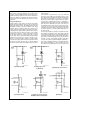
FIGURE 20. Capacitive Transducer
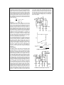
The linearity of voltage controlled oscillators can be improved by employing the LM2907 as a feedback control element converting the frequency back to voltage and comparing with the input voltage. This can often be a lower cost
solution to linearizing the VCO than by working directly on
the VCO itself in the open loop mode. The arrangement is
illustrated in Figure 22.
Analog Systems Building Block
The LM2907, LM2917 series characterize systems building
block applications by the feature that the output from the
device is proportional only to externally programmed inputs.
Any or all of these inputs may be controlled inputs to provide the desired output. For example, in Figure 20 the capacitance transducer can be operated as a multiplier. In
flow measurement indicators, the input frequency can be a
variable depending on the flow rate, such as a signal generated from a paddle wheel, propeller or vortex sensor4. The
capacitor can be an indication of orifice size or aperture
size, such as in a throttle body. The product of these two will
indicate volume flow. A thermistor could be added to R1 to
convert the volume flow to mass flow. So a combination of
these inputs, including control voltage on the supply, can be
used to provide complex multiplicative analog functions with
independent control of the variables.
Phase-locked loops (PLL) are popular today now that low
cost monolithic implementations are available off the shelf.
One of their limitations is the narrow capture range and
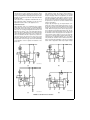
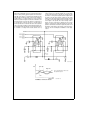
hold-in range. The LM2907 can be employed as a PLL helper. The configuration is shown in Figure 21. The LM2907
here serves the function of a frequency-to-voltage converter
which puts the VCO initially at approximately the right frequency to match the input frequency. The phase detector is
then used to close the gap between VCO and input frequency by exerting a control on the summing point. In this way,
given proper tracking between the frequency-to-voltage
converter and the VCO, (which is a voltage-to-frequency
converter), a wide-range phase loop can be developed.
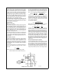
TL/H/7451 – 40
FIGURE 22. Feedback Controlled VCO
Digital Interface
A growing proportion of the complex control systems today
are being controlled by microprocessors and other digital
devices. Frequently they require inputs to indicate position
or time from some mechanical input. The LM2907 can be
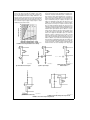
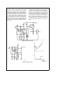
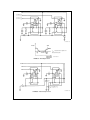
used to provide zero crossing datum to a digital system using the circuits illustrated in Figure 23. At each zero crossing
of the input signal the charge pump changes the state of
capacitor C1 and provides a one-shot pulse into the zener
diode at pin 3. The width of this pulse is controlled by the
internal current of pin 2 and the size of capacitor C1 as well
as by the supply voltage. Since a pulse is generated by each
zero crossing of the input signal we call this a ‘‘two-shot’’
instead of a ‘‘one-shot’’ device and this can be used for
doubling the frequency that is presented to the microprocessor control system. If frequency doubling is not required
and a square wave output is preferred, the circuit of Figure
24 can be employed. In this case, the output swing is the
same as the swing on pin 2 which is a swing of half supply
voltage starting at 1 VBE below one quarter of supply and
going to 1 VBE below three-quarters of supply. This can be
increased up to the full output swing capability by reducing
or removing the negative feedback around the op amp.
TL/H/7451 – 39
FIGURE 21. Phase-Locked Loop Helper
Added f to V Greatly Increases Capture and Hold Range
13