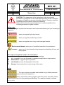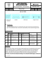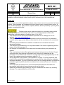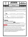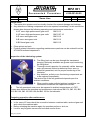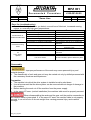
1
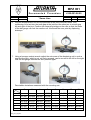
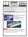
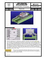
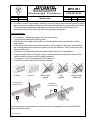
Documented ProcedureBPA
MPZ 001
Documented
Department
Rev. Index
Date
TB / Schell
D
3.05.2011
Procedure
Assembly Plan – Toothed Racks
Servo Line
4100-001-06.05
Page
Name
released
Drive Systems
Rack and Pinion Drives
MPZ_001_engl.doc
1
01.06.05
01.06.05
24
Schell
Lorch
Documented ProcedureBPA
MPZ 001
Documented
Department
Rev. Index
Date
TB / Schell
D
3.05.2011
Procedure
Assembly Plan – Toothed Racks
Servo Line
4100-001-06.05
Page
Name
released
2
01.06.05
01.06.05
24
Schell
Lorch
Table of Contents
Company address
……………………………………………………………….….2
Safety notes
….............................……………………………………………….….3
Signs and symbols
………………………………………………………………..….3
Safety
………………………………………………….……………………………..…3
Item number
…………………………………………………………………………...5
Identification
…………………………………………………………………………...6
Description ….…………………………………………………………………….…….……6
Owerview of racks…………………………………………………………………...….……6
Proper use …………………………………………………………………………………...7
Transport and handling …………………………………………………………………...8
Storage
……………………………………………………………………………….…..9
Preparing the installation
…………………………………………………………...9
Mounting instructions ..………….……………………………………………….…….10
Contact surface
…………………………………………….………………….…10
Pinning
……………………………………………………………………….….13
Contact and supporting surfaces…….………………………………..…………....14
Pinning
……………………………………………………………………..……15
Mounting the gear unit ……………………………………………………………..……16
Engaging the gear unit …………………………………………………………..………17
Final inspection …………………………………………………………………..………17
Operating conditions pinion / rack …………………………………………..………19
Starting up the lubricator unit …..……...…….………………………….…..…………19
Maintenance
………………………………………………………………….…..…...20
Putting out of operation, preparation
……………………………………………20
Visual check
……………………………………………………………………21
Inspection of the lubricating system
……………………………………………21
Restarting operation after maintenance
……………………………………………21
Error list (troubleshooting)
……………………………………………………………22
Disassembly
…………………….……………………………………………………..22
Preparation ……………………………………………………………………………22
Disassembling the rack ……………………………………………………………23
Lubricants ………………………………………………………………………………...…23
Lubrication of rack and pinion drives
……………………………………...…….23
Disposal
……………………………………………………………………………...……24
Lubricants ……………………………………………………………………………24
Seals ………………………………………………………………………………...…24
Metals
……………………………………………………………………………24
Hoses
……………………………………………………………………………24
Felt gearwheels
……………………………………………………………………24
Company contact
ATLANTA Antriebssysteme
Telephone 0049(0)7142-7001-0
E. Seidenspinner GmbH & Co. KG
Telefax
0049(0)7142-7001-99
Adolf-Heim-Straße 16/18
E-Mail
[email protected]
http://www.atlantagmbh.de
D 74321 Bietigheim-Bissingen
Internet
MPZ_001_engl.doc
Documented ProcedureBPA
MPZ 001
Documented
Department
Rev. Index
Date
TB / Schell
D
3.05.2011
Procedure
Assembly Plan – Toothed Racks
Servo Line
4100-001-06.05
Page
Name
released
3
01.06.05
01.06.05
24
Schell
Lorch
CAUTION! The observance of the instructions in this documented
procedure is prerequisite for the undisturbed operation and the contingent
acceptance of liability on account of possible defects. Therefore study the
operating instructions before starting the assembly.
Make sure that this documented procedure is made accessible to the
mounting personnel in legible condition.
Safety notes
The following signal symbols and words are used in the instructions to give you a warning or
suggestion.
warns you against high injury hazard.
warns you against possible injury hazard.
warns you against minor injury and/or damage hazards.
Environmental hazard warns you of a pollution hazard for the environment.
Transport
warns you of injury hazards during transport and handling of heavy and
bulky objects.
Other signs and symbols used in the instructions:
☞
by a „handling instruction“ you are asked to do something.
☺
by a „suggestion“ you are informed of a possible simplification or improvement.
Maintenance: suggests optimal operation.
Identification: shows the description of the rack.
ִ
Storage: informs about the correct storage of the racks.
Safety
The racks may be assembled and installed only by skilled personnel
having the necessary knowhow and experience.
Always wear safety helmet, goggles, protective gloves, and safety shoes
when lifting the rack out of its packing and handling it. For reasons of weight, a second
MPZ_001_engl.doc
Documented ProcedureBPA
MPZ 001
Documented
Department
Rev. Index
Date
TB / Schell
D
3.05.2011
Procedure
4100-001-06.05
Page
Name
released
Assembly Plan – Toothed Racks
Servo Line
4
01.06.05
01.06.05
24
Schell
Lorch
person should be called in or a crane be used, if the weight exceeds 8 kg. Always have a
second person lend a hand, if the length exceeds 1000 mm in order to prevent bending and
injury due to false posture. The crane must always be operated by a crane driver. The rack
to be carried must be properly secured and, if necessary, the ends of the rack marked in a
clearly visible way. There must always be sufficient safe distance from hanging loads. Make
sure that there are no persons present under overhead loads.
Improper handling of heavy loads may lead to serious or even deadly
injuries.
☺ The table below shows the masses of the individual racks. The lengths are rounded
to round figures. The mass stands for the biggest cross-section.
Module
Length
(mm)
200
250
500
1000
1500
2000
3000
1
1.5
1.591
2
2.5
0.41
0.82
1.64
-
0.51
1.03
2.06
4.11
-
0.39
0.78
1.55
-
0.85
1.00
2.20
4.40
6.15
8.80
8.49
1.10
2.21
4.38
8.80
-
Mass of the rack in kg
3
3.183
4
5
6
8
10
2.70
2.70
3.00
4.40
9.50 10.67
1.61
1.55
2.83
3.44
4.83 11.10
3.22
3.10
5.65
6.90 10.50 22.38
6.44
6.20 11.31 17.10 25.00 44.85 70.60
9.66
19.97 20.40 30.30
12.88 12.40 22.61 34.20 50.00 89.71
19.32
33.93
-
12
18
120
Mark the swivelling radius of the rack with a warning sign and a barring
tape. This area must be blocked during transport and handling so that no persons may be
endangered.
Before starting transportation, the path must be inspected for possible
slipping hazards or other disturbing influences and, if necessary, made safe.
Before starting transportation it must be ascertained that the overall
dimensions of the rack permit safe handling. Possible obstacles are to be removed or
bypassed.
Always wear gloves when handling racks, because racks (especially
those with helical teeth) have sharp edges.
In order to avoid injury due to false posture the height of the mounting
bench must be chosen in such a way that it suits the height of the mechanic. An adjustable
MPZ_001_engl.doc
Documented ProcedureBPA
MPZ 001
Documented
Department
Rev. Index
Date
TB / Schell
D
3.05.2011
Procedure
Assembly Plan – Toothed Racks
Servo Line
4100-001-06.05
Page
Name
released
5
01.06.05
01.06.05
24
Schell
Lorch
mounting bench would be needed if mechanics of different height were to work at the same
bench.
Suitable supports or trestles must be provided in order to prevent hand
or fingers from being squeezed and bruised when depositing the unit onto the bench or on
a table.
It is also important to consider the point of gravity of the rack when
setting it down because otherwise the unit could tilt or fall. Consequences could be heavy
contusions of the limbs. A suitable support should also be provided when displacing the
elements to avoid bending.
For fitting the screws, a suitable working height should be chosen for
the mechanic. Furthermore it is important to choose a suitable screwdriver to avoid shocks
within the wrist. The work surroundings must be perfectly prepared for this process in order
to avoid becoming bruised while working.
Whenever having touched the rack without gloves, wash your hands
after work because the racks are oiled.
In order to avoid micro-sliding all racks must be pinned in addition to
being fastened with fixing screws. This additional pinning prevents the rack from
changing its position and also the fixing screws from loosening.
Item number
☺ The item number A) is on the rack.
☺ Example: Racks for continuous linking.
MPZ_001_engl.doc
Documented ProcedureBPA
MPZ 001
Documented
Department
Rev. Index
Date
TB / Schell
D
3.05.2011
quality and
precision
Procedure
Assembly Plan – Toothed Racks
Servo Line
module
4100-001-06.05
Page
Name
released
with bores
6
01.06.05
01.06.05
24
Schell
Lorch
length of rack
Identification
☞ The rack is identified by item number and order code as well as the manufacturer’s
logo. This identification also ensures the retraceablitiy of the manufacturing process.
Overview of racks
Class
Helical toothed
Series
Module
Straight toothed
Heat-treatment
Tolerance
Series Module
of teeth
of teeth
46 .. … 5; 6; 8; 10; 12
28 .. … 2; 3; 4; 5
induction hardened
case- hardened
4
5
UHPR
48 .. … 5; 6; 8; 10; 12
29 .. … 2; 3; 4; 5
HPR
29 .. … 2; 3; 4
28 .. … 2; 3; 4
29 .. … 1,5; 2; 3; 4; 5; 6; 8; 10; 12 28 .. … 2; 3; 4; 5; 6; 8; 10; 12
29 .. … 2; 3; 4; 5; 6; 8; 10
28 .. … 2; 3; 4; 5; 6; 8
carburized- hardened
induction hardened
induction hardened
6h
6h
7h
PR
39 .. … 2; 3; 4; 5
38 .. … 2; 3; 4; 5
induction hardened
quenched and tempered
8h
8 e 27
BR
47 .. … 1,5; 2; 3; 4; 5; 6; 8; 10
25 .. … 1; 1,5; 2; 3; 4; 5; 6; 8; 10 soft
39 .. … 1,5; 2; 3; 4; 5; 6; 8; 10; 12 27 .. … 1; 1,5; 2; 3; 4; 5; 6; 8; 10 induction hardened
34 .. … 2; 3; 4; 5; 6
induction hardened
34 .. … 2; 3; 4; 5
33 .. … 2; 3; 4; 5
9 e 27
10 e 27
10 e 27
Description
Rack and pinion drives convert the rotary motion and torque of a gearwheel into the powertransmitting linear motion of a toothed rack. This takes place when the operating pitch
cylinder of the gearwheel meshes with the common pitch surface of the rack without
slipping. The rolling axis is thus the instantaneous axis of motion of the gearwheel in
relation to the rack. In rack and pinion drives the motion is transmitted by positive
connection. The teeth are therefore shaped in such a way that imaginary pitch cylinders can
be inscribed in both functional partners rolling on one another without slipping. At the point
MPZ_001_engl.doc
Documented ProcedureBPA
MPZ 001
Documented
Department
Rev. Index
Date
TB / Schell
D
3.05.2011
Procedure
Assembly Plan – Toothed Racks
Servo Line
4100-001-06.05
Page
Name
released
7
01.06.05
01.06.05
24
Schell
Lorch
of contact the peripheral speed of both operating pitch circles is identical. Racks are
available in different designs to be chosen by the customer to suit the intended use.
Proper use
Toothed racks are used in applications where rotary motions are to be converted into linear
motions. The advantage, as compared with other types of gear units with linear motion, is
their excellent efficiency, high precision, speed, stiffness, and the possibility of joining them
infinitely one behind the other.
Toothed racks may be used exclusively for converting rotary motion
with torque into power-transmitting linear motion in machine and plant construction
applications under atmospheric conditions from +10 to +60°C.
☞ The maximum force values permissible are specified in our catalogue or on our
website: http://www.atlantagmbh.de
☞ The layout must be made strictly in accordance with our instructions. Any deviation
requires written approval by Atlanta; otherwise this will be considered non-contractual
use.
☞ Exceeding the permissible force shall be considered non-contractual use and is
therefore forbidden.
☞ The maximum permissible force is only transmittable if the screw is tightening with the
torque of the table on page 10
☞ No changes or modifications of the rack must be made without prior permission by
Atlanta.
☞ The case-hardened racks (StrongLine) are hardened and ground on all sides. Except
at the pin holes they must be consumed in use, this may no reworking can be
performed. In the helical rack module 4, only one side to the ongoing assembly can be
used. (See catalog servo-drive systems, page ZA - 5).
☞ Wrong alignment (see chapter „Final Inspection“ on page 17) of the gearwheel with
relation to the rack shall be considered non-contractual use and is therefore forbidden.
☞ Improper lubrication, e.g. lack of lubricant and/or use of a wrong lubricant, or insufficient
protection against pollution shall be considered non-contractual use and is therefore
forbidden.
☞ If several racks are linked in line, it must be assured that the pitch lies within the
permissible individual pitch error tolerances also at the joints.
☞ Atlanta will not assume any liability for any non-contractual use and/or any resulting
damage. The responsibility lies with the user.
MPZ_001_engl.doc
Documented ProcedureBPA
MPZ 001
Documented
Department
Rev. Index
Date
TB / Schell
D
3.05.2011
Procedure
Assembly Plan – Toothed Racks
Servo Line
4100-001-06.05
Page
Name
released
8
01.06.05
01.06.05
24
Schell
Lorch
Transport and handling
☞ Observe all safety regulations applying to transport and handling with lifting gear.
☞ Make sure that the load is handled and set down slowly and carefully.
☞ Especially when transporting and handling long racks (≥ 2000 mm), avoid any leverage
upon the rack. Favourable lever arm ratios are as shown in the following drawing:
☞ If necessary, have one or more persons lend a hand.
☞ Transportation is possible within a temperature range from –10 to +60°C.
☞ The appropriate kind of packing is chosen dependent on the means of
transportation which may be by air, by land or by sea:
- Airfreight: In boxes
- By truck: In boxes or on transport pallets
- By sea: In boxes or containers.
☞ For handling pallets or boxes suitable handling equipment should be used.
Improper handling of heavy loads may cause serious or even deadly
injuries.
Improper handling or transportation may lead to transport damages.
☞ Heavy shocks are to be avoided.
☞ The packing should be removed only as much as is necessary for further internal
transportation.
ִ
Storage
If the rack is not going to be installed immediately after delivery, the following measures
should be taken:
☞ Protect the rack against corrosion. The storerooms must be dry. Remove the anticorrosive agent only immediately before the installation. When storing for a period of
more than one month, renew the anti-corrosive coating.
MPZ_001_engl.doc
Documented ProcedureBPA
MPZ 001
Documented
Department
Rev. Index
Date
TB / Schell
D
3.05.2011
Procedure
Assembly Plan – Toothed Racks
Servo Line
4100-001-06.05
Page
Name
released
9
01.06.05
01.06.05
24
Schell
Lorch
☞ Avoid any unfavourable leverage on the rack during storage (for lever ratios see
paragraph “Transport and handling”).
☞ Protect the rack against dust or other pollution.
☞ Do not damage the teeth or the supporting/contact surfaces.
☞ Avoid any metal-to-metal contacts between the racks during storage. Put a layer of
protective foil or oil paper between them.
Unpackíng
☞ Check the delivery for completeness by means of the accompanying documents.
Wear gloves for unpacking the rack because it is oiled and may
have sharp edges.
☞ Check the rack for damage. Any transport damages should be reported
immediately.
☞ Dispose of packing materials as required by the local disposal regulations.
Preparing the installation
Lifting gear may be required for the installation oft he racks. Make
sure that suitable, sufficiently dimensioned equipment is available.
☞
☞
☞
☞
☞
Adjust your torque wrench and check its function.
Wear gloves while assembling in order to avoid contact corrosion.
Inspect the racks for external damage and soiling.
A damaged or soiled rack must neither be mounted nor operated.
All contact and supporting surfaces of the rack and the machine bed must be
degreased and cleaned carefully.
☞ The threaded holes in the machine bed must not be degreased since otherwise the
friction value would be too high when tightening the screws and the required initial
stressing force of the screw would not be reached. Apply a little bit of oil, if
necessary.
☞ Use screws as supplied (neither oil, nor degrease them).
☞ Use only grade 12.9 screws.
MPZ_001_engl.doc
Documented ProcedureBPA
MPZ 001
Documented
Department
Rev. Index
Date
TB / Schell
D
3.05.2011
Procedure
Assembly Plan – Toothed Racks
Servo Line
4100-001-06.05
Page
Name
released
10
01.06.05
01.06.05
24
Schell
Lorch
Mounting instructions
Contact surface
The machine bed should enable easy installation and
grease-free mounting of the rack.
1. Position the first rack on the machine bed, adjust it
concentrically, and clamp it to the contact surface with a
screw clamp. Insert the hexagon socket screws without
fully tightening them yet. Adjust the supporting surface of
the rack in relation to the machine guide. Then tighten the
hexagon socket screws as shown in the torque table
below, beginning in the middle and continuing outwards.
The screw clamps may be removed.
Hexagon socket screws 12.9
Tightening torque in Nm
Tightening torque in lbf in
M6
16
142
Contact surface
No supporting surface available
agefläche vorhanden
M8
40
354
M12
135
1195
M16
340
3010
M20
660
5842
M30
2300
20357
M36
4100
36288
Fit the second rack at the joint and
clamp it with screw clamps
against the contact surface of the
machine bed. Insert the hexagon
socket screws and tighten them
slightly so that aligning is still
possible. The screw clamps may
be removed.
2. Insert the mating companion piece over the joint so that it meshes with the teeth of
the two racks and fix it on the opposite using a suitable contact surface.
Mating piece
Suitable
contact surface
MPZ_001_engl.doc
Documented ProcedureBPA
MPZ 001
Documented
Department
Rev. Index
Date
TB / Schell
D
3.05.2011
Procedure
Assembly Plan – Toothed Racks
Servo Line
4100-001-06.05
Page
Name
released
11
01.06.05
01.06.05
24
Schell
Lorch
☺ Mounting example on the machine bed
3. Remove the mating companion piece and the auxiliary contact surface.
4. Exact alignment of the racks at the joint
is obtained with the aid of a mounting set
consisting of a displacement device, three
magnetic measuring rolls and a measuring
bridge with dial gauge as well as a hexagon
wrench.
☺ Suitable sizes and a description can be
taken from our servo catalogue or our
web-site: http://www.atlantagmbh.de.
5. Put the measuring bridge on a smooth-ground surface and set the dial gauge to
zero.
zero setting
MPZ_001_engl.doc
Documented ProcedureBPA
MPZ 001
Documented
Department
Rev. Index
Date
TB / Schell
D
3.05.2011
Procedure
4100-001-06.05
Page
Name
released
Assembly Plan – Toothed Racks
Servo Line
12
01.06.05
01.06.05
24
Schell
Lorch
6. Plug the displacement unit into the pinholes at the joint of the two racks. One
measuring roll is laid into the tooth gap at the joint and the other two in a tooth gap
left and right of the joint. Position the measuring bridge on the rolls so that the feeler
of the dial gauge can feel the medium roll. Now seek the zero point by displacing
sideways.
7. Using a hexagon socket wrench adjust the set-screw of the displacing unit in such a
way that the rack, which is not yet firmly screwed, can be moved to the left or the right
until the dial gauge reaches the zero position again.
Permissible deviations measured with the mounting set:
m
Q
4
5
6
7
8
9
10
MPZ_001_engl.doc
2
3
4
5
6
8
10
12
±0.007
±0.01
±0.014
±0.027
±0.027
±0.041
±0.008
±0.011
±0.015
±0.03
±0.03
±0.042
±0.008
±0.011
±0.023
±0.032
±0.032
±0.045
±0.004
±0.008
±0.016
±0.023
±0.033
±0.033
±0.047
±0.004
±0.016
±0.036
±0.049
±0.004
±0.014
±0.038
-
±0.004
±0.015
±0.041
-
±0.16
±0.062
-
Documented ProcedureBPA
MPZ 001
Documented
Department
Rev. Index
Date
TB / Schell
D
3.05.2011
Procedure
Assembly Plan – Toothed Racks
Servo Line
4100-001-06.05
Page
Name
released
13
01.06.05
01.06.05
24
Schell
Lorch
8. Slightly tighten the hexagon socket screws on the not yet fully fixed rack and
loosen the set-screws at the displacement unit. Remove the displacement unit from
the pinholes of the racks.
9. Using a torque wrench tighten the hexagon socket screws as shown in the torque
table one after the other starting in the middle and continuing outwards.
10. Check the pitch once more and repeat steps 5 to 9, if necessary.
11. Racks shorter than 1 m must be additionally pinned.
Pinning
☞
Clamp the rack with screw clamps at all
pinholes as shown on the picture.
☞ Drill the pinholes into the machine bed
to match the holes provided in the rack.
☞ Ream each pair of holes
simultaneously to the required
tolerance fit H7 for the straight pins.
MPZ_001_engl.doc
Documented ProcedureBPA
MPZ 001
Documented
Department
Rev. Index
Date
TB / Schell
D
3.05.2011
Procedure
Assembly Plan – Toothed Racks
Servo Line
4100-001-06.05
Page
Name
released
14
01.06.05
01.06.05
24
Schell
Lorch
☞ Now fix the racks permanently with the straight pins. For this purpose we
recommend to use hardened straight pins according to DIN EN ISO 8734.
☞ All racks must be pinned in addition to being fastened with fixing screws in order to
prevent micro-sliding. This additional pinning prevents the rack from changing its
position and also the fixing screws from loosening.
☞ Notice applicable to tensioning gearboxes: If the torque is transmitted via a tensioning
gearbox or tensioning system where 2 pinions are in mesh on the same rack, the entire
torque must not exceed the displacement force of the screws. The rack should be as
long as possible but not shorter than 1 meter. Please contact us.
The machine bed has contact and supporting surfaces
The rack has a chamfer between contact surface and
supporting surface in order to assure a perfect fit in the
machine bed. The machine bed should enable easy
mounting of the rack.
1. Position the first rack on the machine bed against the contact surface and the supporting
surface, adjust it concentrically and clamp it with screw clamps to these surfaces. Then
insert the hexagon socket head screws and tighten them according to the torque table on
page 8, starting in the middle and continuing outwards. Position the second rack at the joint
and clamp it with screw clamps to the contact and supporting surfaces of the machine bed.
Insert the hexagon socket head screws and tighten them slightly so that the racks can still
be adjusted. The screw clamps may be removed.
Mating piece
MPZ_001_engl.doc
Clamping device
2. Insert the mating companion piece over
the joint so that it meshes with the teeth of
the two racks and clamp it with a suitable
clamping device on the supporting surface.
Documented ProcedureBPA
MPZ 001
Documented
Department
Rev. Index
Date
TB / Schell
D
3.05.2011
Procedure
Assembly Plan – Toothed Racks
Servo Line
4100-001-06.05
Page
Name
released
15
01.06.05
01.06.05
24
Schell
Lorch
3. Tighten the hexagon socket screws
of the second rack in such a way that
adjustment is still possible. Then
remove the companion piece.
☺
The following is a mounting example on the machine bed
☞
Steps 4 to 10 are the same as with the mounting instruction without
supporting surface.
Pinning
☞ Clamp the rack with screw
clamps at all pinholes as shown
on the picture opposite.
☞ Drill the pinholes into the machine
bed according to the holes
provided in the rack.
☞ Ream the drilled holes together to
the tolerance fit H7 for the
straight pins.
MPZ_001_engl.doc
Documented ProcedureBPA
MPZ 001
Documented
Department
Rev. Index
Date
TB / Schell
D
3.05.2011
Procedure
Assembly Plan – Toothed Racks
Servo Line
4100-001-06.05
Page
Name
released
16
01.06.05
01.06.05
24
Schell
Lorch
☞ Now secure the rack permanently with straight pins. We recommend to us hardened
straight pins acc. to DIN EN ISO 8734.
☞ All racks must be pinned in addition to being fastened with fixing screws in order to
prevent micro-sliding. This additional pinning prevents the rack from changing its
position and also the fixing screws from loosening.
☞ Notice applicable to tensioning gearboxes: If the torque is transmitted via a tensioning
gearbox or tensioning system where 2 pinions are in mesh on the same rack, the entire
torque must not exceed the displacement force of the screws. The rack should be as
long as possible but not shorter than 1 meter. Please contact us.
Mounting the gear unit
Before mounting the gear unit on the machine
table it must be equipped with pinion shaft
and lubricator.
(See separate instructions).
The machine table must be designed in such
a way that the gear unit can be readily
mounted and adjusted.
An example is shown on the picture below.
In the case of Z axes (vertical assembly) the machine table must be
properly secured before positive connection with rack and gear unit because otherwise it
could roll off due to its own weight and cause personal injury and material damage.
☞ Mount the gear unit provisionally on the machine table. Do not yet fully tighten the
fixing screws. Mounting example: see picture below.
MPZ_001_engl.doc
Documented ProcedureBPA
MPZ 001
Documented
Department
Rev. Index
Date
TB / Schell
D
3.05.2011
Procedure
Assembly Plan – Toothed Racks
Servo Line
4100-001-06.05
Page
Name
released
17
01.06.05
01.06.05
24
Schell
Lorch
Engaging the gear unit
☞ Push the adjusting unit, consisting for example of the gear unit and two lateral angle
irons, manually into the gearing until the pinion meshes with only little backlash with the
rack. Then slightly fix the adjusting unit with the screws. Move it over the length of the
travelling path and seek the high point. When the pinion is properly engaged in the rack
the adjusting unit can be fixed permanently; if not, it must be readjusted. At the low point
of the traverse there will be a play of the tooth flanks the size of which depends upon
the quality of rack and pinion. Depending upon the quality of the rack the circumferential
backlash can vary more or less.
Do not mount the pinion to the rack under tension so as to produce
freedom from backlash. This would lead to the failure of the gearing
due to wear and tear or rupture of teeth.
MPZ_001_engl.doc
Documented ProcedureBPA
MPZ 001
Documented
Department
Rev. Index
Date
TB / Schell
D
3.05.2011
Procedure
Assembly Plan – Toothed Racks
Servo Line
4100-001-06.05
Page
Name
released
18
01.06.05
01.06.05
24
Schell
Lorch
☺ In order to ensure a traversing movement free from play over the whole travelling length
we recommend to replace the pinion shaft inside the gearbox by a pre-load pinion shaft.
The mounting and adjusting instructions for this item as well as the torque to be
transmitted can be seen from the pertinent operation description.
Final inspection
☞ If necessary, remove the grease from the tooth flanks.
☞ Coat the tooth flanks with marking paint.
☞ Shift the machine table several times so that the pinion runs over the paint coated
tooth flanks.
☞ At the same time check the smooth operation of the gearing. The power required and
the running noise must remain the same over the full distance. There must not be any
bumps at the joints.
☞ Check the area where the paint has been rubbed off from the tooth flanks.
☞ Judge the adjustment of the gear unit by checking the tooth contact by means of the
contact patterns shown on the following sketches.
☞ If necessary, correct the alignment of the gear unit.
☞ Check the racks at the joint for precision of pitch.
Correct
Rechtwinkligkeit
Rectangularity
<0,05mm
mm to
zu A
A
<0.05
Correct
Not at right
angles
Not
parallel
Wrong center
distances
Parallelism
Parallelität
<0.03
mmzutoB B
<0,03 mm
B
A
The rectangularity and parallelism tolerances are only applicable to crowned ATLANTA
gears and pinion shafts.
MPZ_001_engl.doc
Documented ProcedureBPA
MPZ 001
Documented
Department
Rev. Index
Date
TB / Schell
D
3.05.2011
Procedure
Assembly Plan – Toothed Racks
Servo Line
4100-001-06.05
Page
Name
released
19
01.06.05
01.06.05
24
Schell
Lorch
s
ao
The center distance "ao" pinion and rack is set as a
function of the tooth-flank backlash "s":
s = min. 0.03 / max. 0.3
For module 1 to 2,5: s = max. 0,1 mm
For module 3 to 4: s = max. 0,2 mm
For module 5 to 12: s = max. 0,3 mm
This value may be doubled for lifting axles.
Operating conditions pinion / rack
Lacking or insufficient lubrication leads to damage to the teeth.
☞ Ensure proper lubrication and timely replacement of the grease cup.
☞ Pay attention to the correct meshing of pinion and rack.
☞ In the case of X and Y axes (horizontal installation without gearbox) it should be
possible to move the freewheeling machine table by hand uniformly over the full
travelling distance (while checking for tension-free installation). In the case of Z axes the
machine table must be properly secured.
Starting up the the lubricating unit
☺ The lubricating unit consists of a mounting bracket, an
electronically controlled lubricator, a set of connecting
hoses, a mounting axle, and a felt gearwheel.
Depending upon the mounting position on the gearbox,
the felt gearwheel can be fixed on the mounting bracket
in various positions.
☞ When mounting the lubricator on the gearbox, make
sure that the teeth of the felt gearwheel mesh perfectly
with the teeth of the pinion shaft. Due to the rectangular
slots provided in the mounting bracket the lubricating
unit can be displaced on the gear unit.
☞ Before switching on the lubricator, make sure that the hose is filled without any air
bubbles and that the felt gearwheel is filled with suitable lubricant.
☺ Information as to the mounting dimensions, possible mounting positions, and type of
lubricant can be seen from our catalogue or our web-site
http://www.atlantagmbh.de.
☺ If due to restricted space conditions the lubricator cannot be installed as shown above,
the individual components can also be used without the mounting bracket. In this case
MPZ_001_engl.doc
Documented ProcedureBPA
MPZ 001
Documented
Department
Rev. Index
Date
TB / Schell
D
3.05.2011
Procedure
Assembly Plan – Toothed Racks
Servo Line
4100-001-06.05
Page
Name
released
20
01.06.05
01.06.05
24
Schell
Lorch
the attachment of the mounting axle with the felt gearwheel and the supply of the
lubricant from the grease cup by means of the set of connecting hoses must be adapted
to the existing mounting conditions.
☞ Please be aware that in the case of grease lubrication the hose must not be longer than
1.5 m. There must not be any kinks, and before starting up the lubricator, the hose must
be filled with the suitable lubricant without air bubbles. Furthermore the felt gearwheel
must also be soaked with the suitable lubricant.
☞ The center distance „a“ between pinion and felt gearwheel is calculated by the following
formula:
dR + dF
dR – pitch circle of pinion; dF – pitch circle of felt gearwheel
2
☞ The center distance „a“ between rack and felt gearwheel is calculated by the following
formula:
d
a = h0 + F
h0 – pitch height of rack; dF – pitch circle felt gearwheel
2
a=
☺
Further suggestions as to the proper start-up of the whole lubricating system are
contained in the operating instructions BKI 101; BKI 102; BKI 104, and BKI 105.
Maintenance
Putting out of operation, preparations
☞ Mind the instructions in the chapter „Safety“
☞ The machine into which the rack and pinion drive is installed must be shut down.
☞ Cut off the power supply before starting any maintenance work.
☞ In the case of Z axes (vertical installation) the machine table must be properly secured.
When disassembling racks and gear unit, the positive connection to the
machine table is interrupted. If, in the case of Z axes the machine table is not properly
secured, it can roll off due to its own weight thus causing personal injury and material
damage.
☞ Use only original spare parts. Atlanta shall not warrant for other parts.
☞ When replacing racks, always use new screws (see table p.9) and pins.
☞ For pinning, bore the pin holes, which are predrilled in the rack, together with those in
the machine bed to the next bigger pin size. Then ream them simultaneously to the
required H7 fit for straight pins. Continue through all other installation steps as
described in the chapter “Mounting instructions / Pinning”.
☞ Racks may be replaced only by authorized people.
MPZ_001_engl.doc
Documented ProcedureBPA
MPZ 001
Documented
Department
Rev. Index
Date
TB / Schell
D
3.05.2011
Procedure
Assembly Plan – Toothed Racks
Servo Line
4100-001-06.05
Page
Name
released
21
01.06.05
01.06.05
24
Schell
Lorch
Visual check
☞ The entire drive system must be visually checked for external damage and leakage.
☞ Any defective or leaking components are to be repaired immediately. In this connection
please also observe the following operating and maintenance instructions:
☺ HT servo high-performance gear units
BWS 113
☺ HP servo high-performance gear units
BWS 107-10
☺ E servo wormgear units
BWS 110
☺ B servo wormgear units
BWS 112
☺ BG bevel-gear units
BWK 115
☞ Clean pinion and rack.
☞ Product-related information regarding maintenance questions can be ordered from the
ATLANTA technical department.
Inspection of the lubricating system
☺ The filling level can be seen through the transparent
housing. Optionally available are grease cups monitoring
the filling level.
☞ Thorough visual inspection for externally visible damage
such as loosened, kinked or defective hose, worn or
soiled felt gearwheel, and for proper functioning of the
lubricator.
☞ Any defective, soiled or non-functioning components are
to be replaced immediately.
The service life of the felt gearwheel depends upon the
ambient conditions.
☺ When working under polluted ambient conditions, we
recommend to shorten the inspection intervals.
☺
The felt gearwheel must never be exposed to ambient temperatures of >70°C.
Please also observe the operating and maintenance instructions BKI 101; BKI 102; BKI
103; BKI 104; BKI 105; BKI 106 and BKI 109 for the lubricator.
Restarting operation after maintenance
☞ Reinstall all safety devices.
☞ In the case of Z axes check the connection between machine table, rack and gear unit
and unlock the machine table.
☞ Before releasing the machine again for operation perform a test run.
☞ Look for any forgotten screws and tools and remove them.
MPZ_001_engl.doc
Documented ProcedureBPA
MPZ 001
Documented
Department
Rev. Index
Date
TB / Schell
D
3.05.2011
Procedure
Assembly Plan – Toothed Racks
Servo Line
4100-001-06.05
Page
Name
released
22
01.06.05
01.06.05
24
Schell
Lorch
Error list (troubleshooting)
☞ React immediately whenever you detect unusual loss of lubricant, increased running
noises, or unusually high gear temperatures.
Defect
Possible cause
Remedy
Lubricating interval too big
Dosage too small
No lubrication or
Ambient temperature too high
insufficient lubrication
Lubricant dosing device defective
Lubricant dosing device empty
No lubrication or insufficient lubrication
Increased running
noise
Tooth defects such
as
wear, pitting,
rupture
Wrong installation of pinion/rack
Check technical data
Check technical data
Check supply temperature of lubricant
See „Inspection oft he lubricating system“
Replace dosing device
See remedy in case of no or insufficient
lubrication
Check installation and load data, replace
defective parts
See “Final Inspection”
See remedy in case of no or insuffcient
lubrication
See „Final inspection“
Too much stress
Check load data, replace defective parts
Tooth gearing defect
Wrong installation pinion/rack
No lubrication or insufficient lubrication
Disassembly
Improper performance of the work may cause personal injury and
material damage.
☞ The disassembly of rack and gear unit may be carried out only by skilled personnel with
the necessary knowhow and experience.
Preparation
☞ The machine into which the drive system is installed must be shut down.
☞ It must be ensured that the drive system can be removed without danger of damage to
the machine .
☞ Before starting the work cut off the machine from the power supply.
☞ In the case of Z axes (vertical installation) the machine table must be properly secured.
When disassembling the racks and the gear unit the positive connection to
the machine table is interrupted. If, in the case of Z axes, the machine table is not properly
secured, it can roll off due to its own weight thus causing personal injury and material
damage.
MPZ_001_engl.doc
Documented ProcedureBPA
MPZ 001
Documented
Department
Rev. Index
Date
TB / Schell
D
3.05.2011
Procedure
Assembly Plan – Toothed Racks
Servo Line
4100-001-06.05
Page
Name
released
23
01.06.05
01.06.05
24
Schell
Lorch
Disassembling the rack
☞ All fixing screws must be loosened before the rack can be removed from the pinned
fastening with the aid of suitable tools.
☞ Remove the racks carefully in order to avoid damage to the drive system and adjoining
components.
☞ Use only original spare parts. Atlanta shall not warrant for other parts.
☞ When replacing racks, always use new screws (see table p.9) and pins.
☞ For pinning, bore the pin holes, which are predrilled in the rack, together with those
in the machine bed to the next bigger pin size. Then ream them simultaneously to
the required H7 fit for straight pins. Continue through all other installation steps as
described in the chapter “Mounting instructions / Pinning”.
Lubricants
Lubrication of rack and pinion drives:
For the continuous lubrication of rack and pinion drives we recommend
to use electronically controlled lubricators. Together with the electronically controlled
lubricator you can use the felt gearwheel or the sliding brush.
Item numbers and descriptions are contained in our catalogue or the web-site
http://www.atlantagmbh.de.
Recommended lubricants are the following:
☺
Klüber Microlube GB 0
Order code 65 90 002 (1 kg)
☺
Klüber Structovis AHD
Order code. 65 90 003 (1 kg)
The following lubricants have also been tested with good results:
☺
Oest Langzeitfett LT 200
☺
BP Energrease LS EP 00
☺
DEA Glissando 6833 EP 00
☺
Fuchs Lubritech Gearmaster ZSA
☺
Molykote G-Rapid plus 3694
MPZ_001_engl.doc
Documented ProcedureBPA
MPZ 001
Documented
Department
Rev. Index
Date
TB / Schell
D
3.05.2011
Procedure
Assembly Plan – Toothed Racks
Servo Line
4100-001-06.05
Page
Name
released
24
01.06.05
01.06.05
Disposal
Lubricants
Environmental hazard
Lubricants are hazardous substances susceptible to pollute soil and water.
☞ Dispose of the lubricants as required by national regulations.
☞ Never mix polyglycolic substances with mineral oils which are intended for
recycling.
Seals
☞ Sealing rings are to be disposed of as compound materials (metal/plastics).
Metal
☞ The drive components are to be separated as follows:
• Iron
• Aluminium (housings, covers)
• Non-ferrous metal (worm gears; motor windings)
Hoses
☞ Hoses are to be disposed of as plastic materials.
Felt gearwheels
☞ Felt gearwheels can be disposed of as residual waste.
MPZ_001_engl.doc
24
Schell
Lorch