1
PumaVI
Embossing machine
User Manual
Serial No. Embossing Unit:
Serial No. Electronic Cabinet .:
PUMA VI
Blista - Brailletec
_________________________________________________________________________________
Dokumentation
-2-
PUMA VI
Blista - Brailletec
Table of Contents
Technical Data
Working Temperature
Weight
Space Requirement
Embossing specifications
Materials for Printing Plates
Operation
Operating Voltage
Power Consumption
4
4
4
5
5
5
5
5
Installation and Operation
Delivery
Accessories
Options
Control Cabinet Installation
Embossing Unit Installation
Controls
Embossing Unit (overview)
Cautions
Connecting the Puma VI
Operation
6
6
6
7
8
9
11
11
12
13
Operating Modes
Manual Mode
PC Mode (Automatic mode before 2005)
Test Mode
Error Messages in Test Mode
Error Messages in PC and Manual Mode
The Keyboard
15
15
15
15
15
16
Setting and Correcting the Page Format
Large Print
Medium Print
Dot Height
Format Specifications (table)
Adjusting the Dot Height
Top Plate Margin
The Sensors "F1", "F2" and "F3"
Interpoint and Adjustment
17
18
19
19
20
21
21
23
The Control
The Drives
Connectors and Drives
The Embossing Process
24
25
26
_________________________________________________________________________________
Dokumentation
-3-
PUMA VI
Blista - Brailletec
Computerized Operation
The serial port RS 232
Data Coding
Special Codes
Autocorrect System Defaults
Using Older Printer Drivers
Printer Driver
27
27
28
28
29
29
Maintenance Information
Embossing Unit Care Information
Trouble-Shooting
32
32
_________________________________________________________________________________
Dokumentation
-4-
PUMA VI
Blista - Brailletec
Technical Data
Working Temperature
0°-40° C
Weight
Control Cabinet
Embossing Unit
Punch
Case for Control Cabinet
Case for Embossing Unit
Case for Punch
150 kg
85 kg
43 kg
60 kg
58 kg
6 kg
Space Requirement
Embossing unit and
switch board
_________________________________________________________________________________
Dokumentation
-5-
PUMA VI
Blista - Brailletec
Embossing Specifications
Embossing speed
18 cells / per second
Caracter size
Dot spacing
Cell spacing
Cells per line
Line spacing
large print
2.7 mm
6.6 mm
36
10.8 mm
medium print
2.5 mm
6.0 mm
40
10.0 mm
Graphics capability with special Graphics Stamp (fine pitch spacing)
Other printing formats available on request
Printing plate materials:
Size:
Width
Length
Thickness / double-plate
max. 285 mm
max. 340 mm
max. 0.60 mm
Materials:
Zinc:
Aluminium:
Plastic:
degree of purity 99.9 %
DIN 1706
degree of purity 99.5 %
DIN 1712 or 1745
Hard PVC/ Matt / Anti-static
Operation:
Braille keyboard with special keys
Serial Port RS 232: 9600, 8, n, 1
(see page 27)
Operating voltages
selectable from 110 Volt to 240 Volt 50 / 60 Hz
Power consumption
1.1 KW
_________________________________________________________________________________
Dokumentation
-6-
PUMA VI
Blista - Brailletec
Installation and Operation
Delivery
Please check the delivery for completeness first.
The embossing machine consists of:
1
1
1
1
1
1
Embossing Unit
Control Cabinet
Braille Keyboard
Communications Cable
Driver Software (DOS, WIN 9x)
Instruction Manual (incl. documentation for Control Cabinet + Berger SPS)
Accessories
Qty
1
1
1
1
1
1
1
1
1
1
1
1
1
1
1
2
2
Description
Item No.
Adjusting Pin
Set of Transmission Wire
Eye Screw DIN 580 M16
Thickness Gauge
0.05 - 1 mm
Set of Hex Socket Screw Key 1.5-6
Fork Wrench (SW = opening 5.5 and 7) DIN 894
Fork Wrench (SW = opening 13) DIN 894
Fork Wrench (SW = opening 30) DIN 894
Screwdriver for Slotted Screws 4x100 DIN 5270
Screwdriver for Recessed-Head Screws 1x80
Screwdriver for Recessed-Head Screws 2x100
Screwdriver for Recessed-Head Screws 3x150
Clock Oil Type 5 50ml
Plastic Oiler
Sample Printing Plates with brailled Test Sheets
Fuse 16 Amp.
Fuse 6 Amp.
EE - 11 890
EE - 13 809
NO - 10 667
WZ - 10 668
WZ - 10 567
WZ - 10 655
WZ - 10 658
WZ - 10 661
WZ - 10 651
WZ - 13 554
WZ - 13 556
WZ - 13 557
ZU - 10 669
ZU - 13 935
ZU - 14486
ZU - 14487
Options:
Optional Accessories:
1 Toothed Belt X-drive
1 Toothed Belt Y-drive
2 Microswitch
Pneumatic Punch
Graphics Software and Graphics Stamp
_________________________________________________________________________________
Dokumentation
-7-
PUMA VI
Blista - Brailletec
Control Cabinet Installation
Always check shipping case for any damage that may be caused by water, pressure, etc.
1.
Loosen all screws in cover plate "A" and front plate "B" and
remove plates.
2.
Take out Control Cabinet of shipping case gently.
3.
Turn securing feet "C" upwards to move carriage.
_________________________________________________________________________________
Dokumentation
-8-
PUMA VI
Blista - Brailletec
Embossing Unit Installation
1.
Loosen all screws in cover plate "A" and front plate "B"
and remove plates.
2.
Take out spare parts package and Braille Keyboard.
3.
Screw eye screw "C" in Embossing Unit and gently lift out
Embossing Unit of shipping case with a lever or similar and
place it on Control Cabinet.
4.
Screw the ground line of the Control Cabinet to the Embossing
Unit (item "D").
_________________________________________________________________________________
Dokumentation
-9-
PUMA VI
Blista - Brailletec
Controls
Control Cabinet left side:
"A" =
"B" =
"C" =
"D" =
Main Switch
Pilot Lamp power "on"
Key Switch power "on"
Control Cabinet Door Lock
_________________________________________________________________________________
Dokumentation
- 10 -
PUMA VI
Blista - Brailletec
Controls
Control Cabinet right side:
"A" =
"B" =
"C" =
"D" =
"E" =
"F" =
"G" =
"I" =
Braille Keyboard Connector
9-Pin PC Sub-D Connector
Operating Mode Selector Switch
Cancel Trouble Switch
Trouble Light H1
Trouble Light H2
Trouble Light H3
Operating Voltage 24V "on"
Graphics Mode Graph / Text
Control Cabinet Door Lock
_________________________________________________________________________________
Dokumentation
- 11 -
PUMA VI
Blista - Brailletec
Embossing Unit (overview)
A = Positioning and Safety Off-Switch
B = Cable Channel
C = Ground Connection
D = Securing Foot
Cautions:
The PUMA VI was designed for the production of printing plates of the materials
specified in section "Technical Data" only. using other materials may damage the
machine.
Before operation, always check for correct voltage.
The ground cable must be fastened with screws to the Control Cabinet and the
Embossing Unit.
Control and power cables may not be affected by any environmental influence.
It is most important to observe the operating conditions.
All protection devices must be installed before operating the machine.
In order to avoid accidents, never leave any object or your hand within the XCarriage movement area.
Make sure that there is no object under or in-between the printing plate.
_________________________________________________________________________________
Dokumentation
- 12 -
PUMA VI
Blista - Brailletec
Connecting the PUMA VI
1.
First, connect the control cables as shown in the drawing.
These cables are not interchangeable.
2.
Connect the Braille Keyboard.
3.
Plug in the mains cable.
_________________________________________________________________________________
Dokumentation
- 13 -
PUMA VI
Blista - Brailletec
Operation
Before operating the PUMA VI, the operator should read this User's Handbook
thoroughly or attend a training course of the Blista-Brailletec's Servicing Department
to familiarise himself with the operation of the PUMA VI and observe cautions.
Procedure
1.
Open the plate holder and position the plate so that the fixing pins on the
holder are inserted in the holes previously made in the plate. Close
the plate holder "P" to lock the plate in position.
2.
Turn on mains voltage using the Main Switch "C" and then the control
voltage by means of Key Switch "E". Then the Pilot lamp "D" goes on.
.
_________________________________________________________________________________
Dokumentation
- 14 -
PUMA VI
Blista - Brailletec
3.
Turn on control voltage (24 V) with Push-button "F". Then the green
lamp inside this switch goes on. Select the desired operating mode
with Selector Switch "C".
4.
Press Start Button "N" on Embossing Unit. Lamp "O" lights up and the
X-carriage is positioned. Press Start Button "N" again. Now the
machine is ready for work.
.
_________________________________________________________________________________
Dokumentation
- 15 -
PUMA VI
Blista - Brailletec
Operating Modes
The Manual Mode
Set Selector Switch "C" to Hand (right Control Cabinet). The Start Key must be
pressed a second time. The green signal light "0" on the embossing table shows
the machine ready for work. Any braille character entered from the keyboard is
embossed.
The PC Mode (Automatic Mode)
The PC mode allows to emboss a) text in braille or b) tactile
graphics.
a) Embossing Text in Braille
Set Selector Switch "C" to "PC" (right Control Cabinet). Set
Selector Switch "G" for graphics to "Text" ("Grafik aus" before 2005).
Press Start Key N. The green signal light shows the machine ready
for work and the serial port is enabled. Now any text previously
converted into braille characters by the PUMA VI printer driver
program can be received via the serial port.
b) Embossing Tactile Graphics
In order to obtain good-quality print-outs of tactile graphics, you
should first replace the embossing stamp for text print-outs by the
embossing stamp for tactile graphics.
Set Selector Switch "C" to "PC" (right Control Cabinet).
Set Selector switch "G" for graphics to "Graph". Press the
Start Key "N". The green signal light shows the machine ready for
work.
Tactile graphics previously prepared using the BrailleGraf drawing
program can now be received via the serial port.
The Test Mode
Set Selector Switch "C" to Test (right Control Cabinet). Press the
Start Key. The green signal light shows the machine ready for work.
Now a stored test program runs which may be repeated as often as
desired.
The Test Mode allows to test important functions and components
in the PUMA VI. The errors listed below can be shown by the
signal lights H1 through H3 (on right Control Cabinet).
Error Messages in the Test Mode
H1
0
1
0
1
0
1
H2
0
0
1
1
1
0
H3
1
1
0
1
1
0
Embossing sensor defective / Autocorrect System activated
End-of-line sensor defective
Safety switch actuated
Page start sensor/Y-motor defective
Line start sensor defective
X-motor defective
Errors occurring during normal operation of the PUMA VI are shown by the
following error messages:
Error Messages in the Manual / PC Mode
_________________________________________________________________________________
Dokumentation
- 16 -
PUMA VI
H1
0
1
0
0
1
1
1
Blista - Brailletec
H2
0
0
1
1
0
1
1
H3
1
1
0
1
0
0
1
Autocorrect System activated
Carriage jumped onto left limit switch
Safety switch actuated
Carriage moved onto right limit switch
Number of characters exceeds max. line length
number of lines exceeds max. page length
Graphics Mode switch >OFF<
Note:
Any error message shown must first be acknowledged with the red
push-button "D" "Cancel trouble" (right Control Cabinet).
The Keyboard
Key Funktions
Braille Dot 1
Carriage return / Line feed
Braille Dot 2
back space
Braille Dot 3
line feed
carriage return
Braille Dot 4
Braille Dot 5
line back
form feed
Braille Dot 6
Space
The keyboard has a repeat function which starts when a key is kept pressed
down for longer than the time needed for the embossing process.
_________________________________________________________________________________
Dokumentation
- 17 -
PUMA VI
Blista - Brailletec
Setting and Correcting the Page Format
The following information is given for your guidance only.
Modification or re-adjustment of the formats should only be
carried out by trained staff.
The page formats mentioned below are standard and may sometimes
be very different from those in use at the customer's printing house.
If necessary, please ask the Blista Brailletec for more information
about other available formats.
Large Print
_________________________________________________________________________________
Dokumentation
- 18 -
PUMA VI
Blista - Brailletec
Medium Print
_________________________________________________________________________________
Dokumentation
- 19 -
PUMA VI
Blista - Brailletec
Dot Height
Medium Print
Large Print
Format Specifications
Cells per line
Lines per
page
Cells per
page
Medium print
max.40
max.31
1240
Large print
max.36
max.28
1008
Line spacing
Dot 1 to dot 1
Dot spacing
horizontal and vertical
Cell spacing
Dot 1 to dot 1
Medium print 10.00mm
2.50mm
6.00mm
Large print
2.70mm
6.60mm
10.80mm
_________________________________________________________________________________
Dokumentation
- 20 -
PUMA VI
Blista - Brailletec
Adjusting the Dot Height
Should the dot height be re-adjusted after exchanging the embossing pins or after
a longer period of use, then proceed as follows:
1.
2.
Loosen Hex Nut "B".
Re-adjust Shaft Nut "A" to the standard dot height using the adjusting
pin included.
Note:
- Turning Shaft Nut "A" anti-clockwise (see mark +) increases
- Turning Shaft Nut "A" clockwise (see mark -) decreases the dot height.
- One whole rotation of Shaft mooves the Embossing Unit by approx. 2 mm.
- Turning Shaft Nut by one hole mooves the Embossing Unit by approx. 0.33 mm.
Warning!
The adjustment of the dot height is a tricky problem and must therefore be
carried out with a great deal of care. Never adjust the dot height during the
embossing process.
To adjust the dots to the correct height, increase/decrease by very small
amounts. Embossing with too high dots will cause damage to the machine.
_________________________________________________________________________________
Dokumentation
- 21 -
PUMA VI
Blista - Brailletec
Top Margin of the Plate
The top margin of the plate is determined by the contact angle of Sensor "S". This
ensures that the embossing area has the same position on all printing plates. We
recommend the use of our factory-set top margin. If the width of the top margin must
be re-adjusted for the embossing area, then it is necessary to move the contact angle
accordingly.
Note:
Moving the contact angle to the machine front widens the distance between the
embossing area and the top margin of the plate.
Observe: The minimum distance between Sensor "S" and contact angle is 0.20 mm
and the maximum 1 mm.
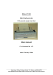
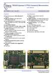
The Sensors "F1", "F2" and "F3"
Sensors "F1" and "F2" determine the beginning of the embossing area at the left
margin of the plate. Switch "D" allows to activate Sensor "F1" or Sensor "F2".
- Activating Sensor "F1" using switch "D" selects the embossing area preferably in
use at the customer's printing house and the standard plate format should be used.
- Activating Sensor "F2" using switch "D" allows the customer to select a second
embossing area. The plate format in use and the embossing area must harmonize
with each other.
- In the "manual mode" Sensor F3 monitors the end of line.
_________________________________________________________________________________
Dokumentation
- 22 -
PUMA VI
Blista - Brailletec
Warning:
Sensors "F1" and "F2" also determines the interpoint quality (see appropriate section).
Therefore their position should not be moved carelessly!
F1 / F2
F3
F3
_________________________________________________________________________________
Dokumentation
- 23 -
PUMA VI
Blista - Brailletec
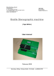
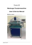
Interpoint Adjustment
In order not to crush the already embossed dots on the front side of the printing plate when
embossing its reverse side, the embossing area on the reverse side must be moved in
horizontal
and vertical direction so that the dots of all braille characters of both sides are embossed
between
the dots of the braille characters of each other side (interpoint). The differing positions of the
embossing areas on the front and reverse sides are determined by the fixing holes
previously made
in the plates for installation on the PUMA VI.
There are two faults that may occur in the interpoint despite high-accuracy in holing the
plates:
1. Both embossing areas are moved against each other in X-direction (line direction)
(see drawing Fault 1 and Fault 2).
2. The printing plate does not move accurately in X- and Y-direction at an angle of 90°
Accurate Interpoint
Fault 1
Fault 2
(Full cell = front side)
1. Adjusting the Interpoint in X-Direction
The positions of the two embossing areas on the front and reverse sides of the plate are
determined by Sensors F1 for the first format and F2 for the second one (see page 21).
Very fine adjustment to the position of the sensors can be made using the set screws
after loosening their holding yokes. In order to adjust the embossing areas for perfect
interpoint, re-adjust the respective sensor by a half of the incorrect displacement.
If dots 1,2,3 in a cell on the plate reverse side are displaced towards dots 1,2,3 of a cell
on the front side (fault 1), then Sensor F1 (or F2) must be moved to the left from the line of
sight of the picture on page 21.
If dots 1,2,3 in a cell on the plate reverse side are
displaced towards dots 4,5,6 of a cell on the front
side (fault 2), then Sensor F1 (or F2) must be moved
to the right from the line of sight of the picture on
page 21.
Printing plate with outlined braille
characters in X- u. Y- direction
2. Re-adjusting the X-Y Orthogonality
If the carriage does not transport the plate on the PUMA
VI at exactly a 90° angle in the X- and Y-directions, then
the characters will be crushed in the interpoint, in parti
cular in the last line of the plate. For re-adjustment, the
bar with the fixing pins for the printing plate must be readjusted by a half of the cell displacement after
loosening the screw at the bottom fixing pin.
.
_________________________________________________________________________________
Dokumentation
- 24 -
PUMA VI
Blista - Brailletec
The Control
The PUMA VI uses a CPU, the so-called Store-Programmed Control "SPS" made by the
Berger Co. to initiate and monitor all of its functions (see enclosed description).
The complete electromechanical construction of the Embossing Unit in the PUMA VI
can be subdivided into the following components:
- X-drive with a five-phase stepper
- Y-drive with a two-phase stepper
- Embossing drive with servomotor and own motor- and position monitoring
- Bottom embossing unit section with rotary magnets and sensors for the
Autocorret System
- Inductive sensors for position monitoring
Note:
All the connectors in the PUMA VI are covered with a loop which checks the PUMA
VI for connecting passage when switched on. The PUMA VI will not start if a connector
is not properly closed!
The Drives
X-Stepper (X-Drive Motor)
The X-drive uses a 5-phase stepper made by the Berger Co. Detailed descriptions of the
Berger stepper are attached to this documentation.
Stepper Y-Drive (Line Feed Motor)
The Y-drive uses a 2-phase stepper and is driven by its own circuit board (line feed
module).The line feed board receives the necessary control signals from the CPU which
are then processed for the Y-drive.
The Embossing Motor
The embossing motor, a servomotor, has its own control unit. This receives a start pulse
from the CPU, however, the actual motor drive (power and speed monitoring) and the
embossing stamp position control via an incremental signal transmitter is initiated and
monitored by this own control unit.
The Bottom Embossing Section (Magnet Unit)
The bottom embossing section has six rotary magnets which are directly driven by
the CPU. The rotary magnets lift the embossing pins over an inclined plane to the
embossing position and lock.
On the embossing unit are installed the sensors for the Autocorrect Systems. These six
sensors monitor the movements of the embossing pins with their electronics. The embossed
character is regenerated from the movement of the embossing pins and compared with the
character previously sent from the PC to the PUMA VI. If there is a difference, The PUMA VI
tries to emboss this character correctly or it stops the embossing process and outputs an
error message (see pages 14, 15).
_________________________________________________________________________________
Dokumentation
- 25 -
PUMA VI
Blista - Brailletec
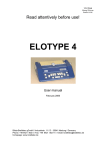
Connectors and Drives
SPS
Note:
The drawing gives you an owerview of connections, drive and sensors of predecessor PUMA
Vb. As PUMA VI consists of similar components ans the same way, we took over the sketch.
_________________________________________________________________________________
Dokumentation
- 26 -
PUMA VI
Blista - Brailletec
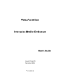
The embossing Process
The timing for the embossing process can be subdivided into two main steps as follows (see
circle diagram):
- Plate movement to the next character position and
- the actual embossing time.
After the PUMA VI has been switched on, the embossing stamp is located in the upper dead
centre. As soon as the start button is pressed to start embossing in the PC mode, the
CPU sets the corresponding pins for the character to be embossed by driving the rotary
magnets. Then the servomotor control receives the command to start the embossing
process.
Then the embossing stamp moves from the upper to the bottom dead centre. The
embossing stamp
touches the plate approx. 8 ms before the bottom dead centre and it has embossed the
character when reaching the bottom dead centre. When reaching the bottom dead centre,
the
servomotor control sends a signal to the CPU. The CPU clears the rotary magnets and
sends
the next character to be embossed to the rotary magnets. After a waiting time of approx.
10.5 ms after the bottom dead centre, the embossing stamp leaves the plate. Now the Xmotor
is started and moves the plate to the next character position. After approx. 37 ms the plate
reaches the new position. In the PC mode, the embossing stamp is not stopped
in the upper dead centre and immediately runs against the plate after it is stopped. And the
embossing process resumes for the next braille character.
Upper dead centre
Rotation time
55,6ms
Embossing
time
Waiting time
Bottom dead centre
_________________________________________________________________________________
Dokumentation
- 27 -
PUMA VI
Blista - Brailletec
Computerized Operation
The serial port RS 232
In order to send a document from a PC to the PUMA VI, the PC must be first connected to
the PUMA VI via a serial port (RS 232). The port in the PC should be configured as follows.
Baud Rate:
Parity:
Data Bits:
Stop Bits:
9,600
none
8 Bit
1
The data transfer is checked using the software handshake with X-on/X-off. The PUMA VI
has the capability of buffering up to 7 pages of braille before embossing.
The PUMA VI is equipped with a 9-pin Sub-D connector with the following pin assignment:
Pin 2:
Pin 3:
Pin 5:
RxD receive data
TxD transmit data
GND
The Data Coding
Text to be printed out must first be converted into the so-called transparent code before
it is sent from the PC to the PUMA VI by character. The conversion of the characters into
the transparent code is done according to the following rules:
A braille character (dots 1 through 6) is represented as a Byte:
1 o o 4
2 o o 5
3 o o 6
Dot 1 =
Dot 2 =
Dot 3 =
Dot 4 =
Dot 5 =
Dot 6 =
Controlbit =
Controlbit =
20
21
2²
2³
24
25
26
27
(LSB)
(MSB)
If a braille dot is contained in a braille character, then the Bit corresponding to the dot is set
to 1. Dots that do not exist in a braille character are encoded with 0.
Example 1: The character "s" is represented in braille by the dots 2, 3, 4. Thus, the Byte
corresponding to the "braille s" is encoded as follows:
27 26 25 24 2³ 2² 21 20
0 0 0 0 1 1 1 0
The Byte corresponds in Hexadecimal code to the value 0E hex.
Example 2: The character "y" is represented in braille by the dots 1, 3, 4, 5, 6. Thus, the Byte
corresponding to the "braille y" is encoded as follows:
27 26 25 24 2³ 2² 21 20
0 0 1 1 1 1 0 1
The Byte corresponds in Hexadecimal code to the value 3D hex.
_________________________________________________________________________________
Dokumentation
- 28 -
PUMA VI
Blista - Brailletec
The ASCII codes of the print characters must be converted in the PUMA VI printer driver
software into the hexadecimal values of the corresponding braille characters.
Example 1: The print character "s" is stored in the PC in ASCII code as 73 hex. Assigned to
the 73 hex in the ASCII-braille table is the value 0E hex.
Example 2: The print character "y" is stored in the PC in ASCII code as 79 hex. Assigned to
the 79 hex in the ASCII-braille table is the value 3D hex.
Special Codes:
The PUMA VI requires special control characters which are encoded as follows:
Character
Blank
Form Feed
Carriage Return / CR
Letter "e"
Letter "h"
ASCII - value in hex
20
0C
0D
65
67
Braille - code in hex
80
83
81 ( 85 / 87 * )
91 (see Note)
93 (see Note)
* The PUMA VI initiates the line feed on its own as soon as it receives the carriage return
character at the end of each line. The carriage return can be performed with the three
following characters, where the value
81
85
87
performs a line feed of
performs a line feed of
performs a line feed of
4 feed units (standard line feed)
3 feed units
2 feed units.
A feed unit corresponds to the dot spacing in the braille cells. For example 2.5 mm in
medium print, 2.7 mm in large print or the dot spacing of a cell size made to customer's
specification. The different line feeds allow the PUMA VI to also emboss 8-dot braille in
interpoint using an appropriate PC program, where the individual 8-dot braille cells are
divided into two characters to first be embossed as 6-dot characters. After a smaller line
feed, dots 7 and 8 can then be added in the next line, for example with pins 1 and 2 of the
embossing head.
Note: 11 hex and 13 hex are the ASCII characters for X-on and X-off. If the indicated
code is not used for "e" and "h", then the PUMA VI interprets each "e" and "h" as X-on/X-off.
This would absolutely cause errors in communication between the PC and the PUMA VI
and provide erroneous print-outs!!
Autocorrect System Defaults
During data transfer, the Autocorrect System in the PUMA VI always checks the braille page
to be embossed for its embossing area already before the embossing takes place characters
per line, lines per page).
Therefore each line must be closed with a CR (81 / 85 / 87 hex) and the last line of each
page finished with an end-of-page character only (83 hex).
The selected embossing format presets the embossing area for the PUMA VI. If the embossing area sent from the PC to the PUMA VI does n o t correspond to the preset one, then
no embossing will take place. In this case the PUMA VI outputs an error message using
signal lamps H1 through H3 (see page 15).
_________________________________________________________________________________
Dokumentation
- 29 -
PUMA VI
Blista - Brailletec
The PUMA VI monitors the embossing area by counting each character sent via the port. Fill
characters, such as 00 hex or FF hex, are also counted and n o t skipped or cleared.
Using Older Printer Drivers
There are two alternatives for the PUMA VI to operate using an existing PC program,
e.g. for the PUMA V:
1) Changing the software of the existing program
Change the older printer driver program as follows:
a) Handshake from
hardware handshake with DTR to
software handshake with X-on / X-off.
b) In the ASCII braille table, change
the code for "e" from 11 hex to 51 hex and
the code for„h" from 13 hex to 53 hex.
Background information: 11 hex and 13 hex are the ASCII characters for X-on and X-off. If
the characters "e" and "h" are not changed as described, the PUMA VI interprets each "e" /
"h" as X-on / X-off. This would cause communication errors between the PC and the PUMA
VI as well as erroneous print-outs.
A Printer Driver
The PUMA VI can also be operated using our older printer driver software for the PUMA Vb.
This printer driver is always included. Therefore,
- to load the program, enter PUMA.EXE.
- When the logo PUMA V appears on the screen, press <RETURN> and the
following StatusLine will appear on the screen:
StatusLine: | Help Alt-H | COM1: 9600,n,8,1 | EXIT Alt-D
COM1:9600,n,8,1 shows the standard settings of port COM1 for PUMA
VB / VI. COM2 can also be activated from the help menu with (Alt-H).
Alt-D returns you to leave the program. Additionally, however, you will be
asked to confirm:
REALLY, YOU WANT TO LEAVE Y/N?
According to your confirmation, you will leave the program or return to the StatusLine.
Alt-H With this command you will obtain the following help menu:
PUMA V - HELP
Port output
Show ASCII - Braille Table
Load the Reference Table
Leave PUMA V
Send file
Alt - A
Alt - B
Alt - C
Alt - D
PgDn
_________________________________________________________________________________
Dokumentation
- 30 -
PUMA VI
Blista - Brailletec
Alt-A
activates COM1 or COM2.
Alt-B
Calls up the ASCII - Braille Table, in which are declared/assigned the braille dot
combinations to the corresponding characters in the ASCII Table. This table is also
called User Table, since the assignments may be changed by the user. Multiple
codings are possible. To enter a change, open the table by pressing F5, type the
number of the ASCII character to be encoded and press the <RETURN> key. Then
enter the encoded value for the corresponding braille dot combination according to
the example below. Assigned to the braille dots is a fixed valence:
Dot 1 = 1
Dot 2 = 2
Dot 3 = 4
Dot 4 = 8
Dot 5 = 16
Dot 6 = 32
Example: X = braille dots 1,3,4,6 = 1+4+8+32 = 45
The values of the respective dot combination for the braille character are added
and entered as a sum. Then press the <RETURN> key. Each entry must be activated
again with F5 to avoid any unwanted change in the table. To leave the table, press
<ESC>.
Then you will be asked to confirm:
SAVE Y/N?
Alt-C calls up the reference table contained in the program. When called up, the reference
table overlays the user table and restores the original ASCII - braille assignment.
PgDn Pressing this key initiates sending a file from the PC to the PUMA V / PUMA VI.
Then you will be asked to
ENTER FILENAME:
If you fail to enter the correct filename, the following message appears on the screen:
FILE NOT FOUND !
Cancel with |ESC|.
|RET|
Continue with |RET|.
returns you to: ENTER FILENAME
|ESC| returns you to the StatusLine
If an available file has been entered correctly, you will be asked to enter the numbers of the
start page and the last one:
_________________________________________________________________________________
Dokumentation
- 31 -
PUMA VI
Blista - Brailletec
from page:
to page:
and the possibility to cancel
Cancel with |ESC|;
This returns you to the StatusLine.
If the page entered has been correct, the following message will be displayed:
Page x found ! Start with |RET| Stop with |SpaceBar|
|RET|
sends the text to PUMA V. Then the machine starts embossing.
|SpaceBar|
Pressing this key during the embossing process will cause the machine to
emboss the text contained in the buffer memory of PUMA Vb / PUMA VI and
stop when finished.
_________________________________________________________________________________
Dokumentation
- 32 -
PUMA VI
Blista - Brailletec
Maintenance Information
Embossing Unit Care Information
During the embossing process, only the bottom embossing unit section of the PUMA VI is
subject, with its translating parts and embossing pins, to mechanical wear and permanent
soiling in particular. Embossing the dots and moving the metal plate cause rubbed-off parts
of material mixing with oil and forming sticky dirt in the pins guide. Therefore the embossing
pins in the bottom embossing unit section should be cleaned after regularly.The dirt depends
on the material in use. Therefore, we recommend that you first clean the PUMA VI once per
month or every two months maximum and then decide yourself how often the machine
should be cleaned.
Rubbed-off parts from the plates also stick in the holes of the embossing stamp. Therefore,
we recommend that you always watch the holes with a mirror and remove the dirt when
cleaning the embossing pins. To this end, the stamp should be dismounted. The dirt can
easily be removed with a 1.9 mm diameter drill (for medium print) and a 2.0 mm diameter
drill (for large print).
Trouble-Shooting
If the PUMA VI does not emboss what it should do, despite regular maintenance of the
embossing pins and built-in safeguarding systems (embossing area monitoring, Autocorrect
System), start the PUMA VI again and emboss a test page while watching the embossing
process. Does it emboss the customary test pattern? Do all the dots (1 through 6) have the
same height? If any of the signal lights H1 trough H3 shows an error in the test mode and
you are unable to remove the error, then please contact us by MAIL, PHONE, FAX or EMAIL
as indicated below:
Blista-Brailletec gGmbH
Industriestrasse 11
D-35 041 MARBURG / Lahn
Fon: +49 6421 802 0
Fax: +49 6421 802 14
e-mail: [email protected]
_________________________________________________________________________________
Dokumentation
- 33 -