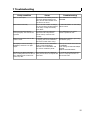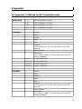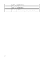
1
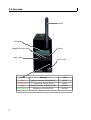
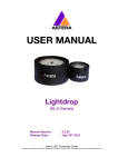
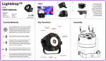
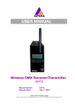
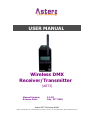
USER MANUAL
Wireless DMX
Receiver/Transmitter
(ART3)
Manual Version:
Release Date:
3.2.20
July. 23rd.2010
Astera LED Technology GmbH
Address : Nahestrasse 68-70, 55593 Rüdesheim an der Nahe, Germany Tel.: +49(0)6536-355361 Email: [email protected]
1 Table of Contents
1 Table of Contents......................................................................................2
2 Safety........................................................................................................3
3 Getting Started.........................................................................................4
3.1 Introduction................................................................................................4
3.2 Overview....................................................................................................5
3.3 Mounting/Connection...................................................................................6
3.4 LCD Display.................................................................................................6
3.5 Navigation...................................................................................................6
3.6 Radio PIN .................................................................................................6
4 Operation Modes.......................................................................................7
4.1 DMX Transmitter.........................................................................................7
4.2 RC Transmitter ...........................................................................................7
4.3 DMX Receiver..............................................................................................8
4.4 RC Receiver................................................................................................9
4.5 Control Lamps...........................................................................................10
5 Setup.......................................................................................................11
6 Technical Data........................................................................................14
7 Troubleshooting......................................................................................15
8 Appendix.................................................................................................16
8.1 Appendix 1: DMX tab for RC Transmitter mode............................................16
8.2 Appendix 1: Customizable Programs...........................................................18
9 Disposal...................................................................................................19
2
2 Safety
Before you operate the unit, read this manual carefully.
Make sure to keep the manual, in case you need to consult this manual again or you give the unit to another
person.
Always make sure to include this manual if you hand out
the unit to another person.
Keep in mind that this manual cannot address all possible dangers and environments. Please use your own
caution when operating.
Do not operate the unit in areas where the usage of radio frequency or mobile phones is prohibited, like for example in airplanes, or when it may cause interference or
danger.
Only qualified personnel may repair this product.
Don't open the case.
This device conforms to CE -or- FCC regulations, see type
label!
This device radiates in the 868 MHz or 915 Mhz bands.
Always make sure, that your national regulations allow
the use of this device!
3
3 Getting Started
3.1 Introduction
Astera's ART3 is a wireless DMX receiver/transmitter that can be used to control a setup of
Astera Lamps and/or third party lamps with a DMX control desk.
There are five operation modes:
1. DMX Transmitter:
Transmits one DMX universe that will be received by all light fixtures or Wireless DMX
receivers that are set up appropriately.
2. RC Transmitter:
the ART3 controls Wireless Astera lamps,
the same way an ARC2 remote control
would do but the parameters are set by an
DMX control table. The whole light setup
can be controlled in a way the ARC2 would
do but there is a DMX desk in control.
The basic advantages of this operation mode are a higher range and that data is only sent
during changes. With only 20 DMX channels you can control a whole setup of lamps.
3. DMX receiver:
one DMX universe can be received.
4. RC Receiver
This mode is useful to integrate third party
RGB lamps into a remote controlled light
setup. Up to 32 RGB fixtures can be connected to the DMX output, all controllable
individually. The ART3 will replay all the programs that can be set up by the remote control.
5. Control Lamps
The ART3 can work as a simple remote
control to set programs and colors similar
to the ARC2 remote control. This is useful if
you forget to bring your ARC2.
4
3.2 Overview
Antenna
LCD Display
Navigate through menu
Confirm
Back / Menu
Power on/off
5
Color
Meaning
XLR
red
Ready to transmit, XLR is INPUT
INPUT
red, flickering
Transmitting, XLR is INPUT
INPUT
green
Ready to receive, XLR is OUTPUT
OUTPUT
green, flickering
Receiving, XLR is OUTPUT
OUTPUT
3.3 Mounting/Connection
3.4 LCD Display
Definition of symbols:
[1] - Receiving
[3] - Transmitting
[4] - Settings are stored in the memory
(shown by a short blinking of this symbol)
[5] - Synchronization between units is active
[8] - Battery status
3.5 Navigation
Navigation is done over the + and – buttons. Enter confirms a selection or moves deeper in
the navigation. Back aborts a selection or moves up in the navigation.
In the top level of the navigation you can choose between the 5 operation modes and the
setup menu.
3.6 Radio PIN
Astera offers the possibility to operate several ART3 that are in reach of each other without
interfering into each others data. Up to 5 different radio PINs can be set for this.
To set a radio pin, choose SETUP, then RADIO PIN and choose a unique number.
This has to be performed for both ART3 that are communicating with each other or
for an ARC2 and ART3 if they are to communicate on a special radio channel.
Although you can use up to five pairs of ART3 or ARC2 in one room it is recommended not
to place them closely together. At least 1m of disctance should be between the transmitting
units to avoid radio interferences. Their performance is influenced by the occupation of the
available frequency bands!
6
4 Operation Modes
As there are numerous settings, it is recommended to do a FACTORY RESET before setting
them up. This can be found in the SETUP menu (chapter 5)
As already explained in paragraph 3.1 on page 5, there are five basic operation modes:
1. DMX transmitter
2. RC transmitter
3. DMX receiver
4. RC receiver
5. Control Lamps
To select a different operation mode, press the plus and minus key until you find the
desired mode. Then press Enter to confirm.
4.1 DMX Transmitter
Simply choose DMX TRANSMITTER to start this mode. The ART3 is already set to
DMX Transmitter when you get it or after you perform a Factory Reset.
As soon as the XLR connector detects a DMX signal the ART3 starts transmitting.
This is indicated by a flickering blue power-LED.
When the DMX signal is lost, the transmission is interrupted.
The DMX data is compressed to fit the bandwidth of the wireless link. Due to this fact, the
frame rate depends on the amount of changes done in the DMX stream between each frame.
Assuming a good RF link, the refresh rate should be at a minimum of 10 Hz; usually it will
stay at 20 Hz – 44 Hz.
4.2 RC Transmitter
To start this mode, choose RC TRANSMITTER in the top navigation and confirm
with Enter.
This operation mode offers several advantages over the Wireless DMX modes and should be
preferred over the DMX Transmitter operation mode. Setting up this operation mode takes
longer then for the DMX Transmitter mode but the advantages are:
1. Much higher RF range.
2. Only 20 DMX channels are needed to control a whole light setup.
3. Easy setup of light fixtures.
4. Less programming effort needed to archive varied light shows.
7
When choosing the RC Transmitter mode you can control ART3 transmitters as well as wireless Astera lamps. Two values can be set in the RC Transmitter mode:
RC DMX Address
Chooses the ART3's input DMX address from 0-511.
DMX Tab
Three DMX tabels that control the lamps can be chosen. Each one has a predefined set of
DMX channels and their effects on the lamps.
A table showing the DMX channels for each tab can be found in Appendix 1.
While the DMX Tabs STANDARD and EXTENDED offer the same possibilities as the ARC2 remote control just that you input the values directly at a DMX light controller the DMX Tab
SIMPLE RGB offers an easy way to set the same color to all lamps in reach of the ART3.
4.3 DMX Receiver
To start this mode, choose DMX RECEIVER in the top navigation and confirm with
Enter.
As soon as a Wireless DMX signal is received by the antenna, the power-LED start flickering
green, and the XLR connector outputs DMX data. If the signal is lost, the transmission stops.
DMX Failure:
When in the DMX Receiver mode you can also set a value for DMX Failure in case the DMX
signal is interrupted and the ART3 does not receive any DMX data. Four values are possible:
Hold:
If the DMX reception times out, the output keeps unchanged and the
last received DMX frame is displayed.
Emergency Light: If the DMX reception times out, the light turns white.
Blackout:
If the DMX reception times out, all light turns black.
Auto Program:
If the DMX reception times out the ART3 displays any of the 20 preprogrammed programs.
8
4.4 RC Receiver
To start this mode, choose RC RECEIVER in the top navigation, confirm with
Enter.
By using the RC Receiver mode, third-party RGB lamps can be integrated in a light setup
that is not controlled by Wireless DMX but by the ARC2 remote control.
Up to 32 externally connected RGB fixtures can be controlled individually. The ART3 has to
be setup to the number of connected pixels, to replay programs correctly. This is done using
the AUTO PIXELS parameter.
Apart from Auto Pixels a range of values can be set to control the connected third-party
lamps directly from the ART3 without the need for an ARC2 remote control:
Auto Pixels
Sets the number of pixels that replay programs. Setting the value to
ten means that a program will stretch over ten lamps.
Local Group
Assigns the lamps to one of the four groups for easy addressing.
Local Set Number Assigns the lamps to one of 256 possible sets for easy addressing.
Program
Plays one of 20 pre-defined programs that can be customized with
colors, intensity, power scheme, speed, fade, directions, etc.
Intensity
Sets the brightness of the lamps.
Power Scheme
Three different power schemes can be set to optimize the lamp for
high-brightness, maximum runtime or normal playback.
Speed
Sets the speed with which a program is played.
Fade
Sets the fading transitions between between different colors from hard
transitions to smooth transitions.
Direction
Sets the direction of a program and whether it loops continuously or is
played only once.
Strobo Speed
Starts the strobe-light and defines the frequency of the strobe effect
Random Mode
Switches a random mode on which displays programs at a changing
rate.
Random Fade
Defines the random fade.
Random Speed
Defines the random speed.
Groups
GROUPS defines over how many of the 4 Groups a displayed program
stretches. Usually this is set automatically by the ART3.
Offset
Offset defines where the LOCAL GROUP starts. Usually this is set
automatically by the ART3.
Chain Size
Creates a chain of lamps that enable programs to stretch over several
lamps.
Position in Chain Assigns a position inside the chain to all lamps connected to the ART3
Set Size
Defines over how many lamps a set stretches.
Position in Set
Defines which position in a set a lamp has.
Color 1
Sets color 1 that is used to display programs
9
Color 2
Color 3
Color 4
Sets color 2 that is used to display programs
Sets color 3 that is used to display programs
Sets color 4 that is used to display programs
4.5 Control Lamps
To start this mode, choose CONTROL LAMPS in the top navigation and confirm
with Enter.
The ART-1 can be used as a remote control, providing basic functionality of the ARC2 remote
control. Although the ARC2 is easier to control as it has more buttons and a more compact
size, the ART3 can do most of the ARC2 functions in case no ARC2 is available.
Target Lamps
Offers a range of possibilities to target several lamps of all the lamps in
range. It is possible to target lamps by type, serial number, group, set
number or by tapping several lamps
Program
Plays one of 20 predefined programs that can be customized with
colors, intensity, power scheme, speed, fade, directions, etc.
Intensity
Sets the brightness of the lamps.
Power Scheme
Three different power schemes can be set to optimize the lamp for
high-brightness, maximum runtime or normal playback.
Speed
Sets the speed with which a program is played.
Fade
Sets the fading transitions between between different colors from hard
transitions to smooth transitions.
Direction
Sets the direction of a program and whether it loops continuously or is
played only once.
Strobo Speed
Starts the strobe-light and defines the frequency of the strobe effect
Random Mode
Switches a random mode on which displays programs at a changing
rate.
Random Fade
Defines the random fade
Use Random Cols Uses random colors to display programs
Color 1
Sets color 1 that is used to display programs
Color 2
Sets color 2 that is used to display programs
Color 3
Sets color 3 that is used to display programs
Color 4
Sets color 4 that is used to display programs
10
5 Setup
The setup offers advanced settings that can be done before or after an event like factory reset, forming groups of lamps, calibrating colors and setting a keylock when giving away the
ARC2.
To enter the SETUP menu, while in the top level of the navigation press the minus
button ( - ) until you see SETUP, then confirm with Enter. If you are not sure in
which level you are, press the home button, to get to the top level.
If SETUP does not appear on pressing the ( - ) button, check the KEYLOCK setting!
Create a Set:
Sets are similar to groups and combine several lamps which can be ad
dressed at the same time and arranged in a preferred order to stretch
effects over them. Unlike groups, a huge number of sets (256) can be
programmed and targeted with the Target Lamps button. A set can also
be applied to only 1 lamp if this lamp needs to be targeted quickly.
Create a Chain: Chained lamps will stretch their effects and programs over several lamps.
For example the FLAG RUNNING program can send a pixel running one
AL6 until it reaches its edge, then continue on the next AL6. To allow a
smooth running along the chain, correct positions have to be assigned to
each lamps.
DMX Setup:
Some Astera lamps do not have a LCD-display so the ARC2 can be used
to set them up for DMX usage. Also, Astera lamps with LCD-display might
be easier configured remotely for DMX because their display cannot be
reached.
DMX Address: Sets the DMX address
DMX Pixels:
All pixels:
Every pixel can be controlled individually
by DMX
Reduced Pixels:
Pixels are combined to achieve a
fewer pixel count for easier control. Please refer to the
manual of the specific device to see how many pixels
will be present on DMX when this setting is chosen.
One Pixel: The device can be controlled with only
three DMX channels. All pixels are combined into one.
DMX Tab:
Several different DMX tables can be chosen.
11
RGB S RGB S..:
For each pixel there are three
channels RGB and one channel stroboscope.
RGB RGB S S..:
All RGB channels are followed by
all stroboscope channels.
Effect Mode Fix:
The 4 user colors are controlled
by one channel per color (generates basic colors).
Effect Mode RGB: The 4 user colors are controlled
by three DMX channels each.
Strobe:
Single:
Multiple:
Off:
DMX Failure:
Remote Setup:
One DMX channel is supplied for the control of the stroboscope function and all
pixels will strobe Identical. When using
this setting, DMX TAB should not be set
to RGB S RGB S ..
For each pixel, the stroboscope can be
controlled individually.
Stroboscope is turned off globally.
Sets the behavior of the light in case of an interrupted
DMX signal.
Hold:
The output keeps unchanged, the last
received DMX frame is displayed.
Emergency Light: If the DMX reception times out,
the light turns white.
Blackout:
If the DMX reception times out, all light
turns black.
Usually all configuration settings, like changing the DMX address,
chain configuration and so on is done directly on the units. This might
not be feasible if several units with the same settings have to be con
figured with the same settings or a unit is not equipped with a LCD-dis
play.
Remote Group chooses one of the 4 groups. Input Select lets
you choose between XLR DMX, Wireless DMX,
Remote Control function. Standalone or Auto.
Input Select
If a lamp has several input signals (for example it is
connected to a DMX cable but should be targeted
by the ARC2) the preferred input signal can be
defined
XLR DMX
for the signal of wired DMX
Wireless DMX for the signal of wireless DMX
Remote Control for the radio signal of the ARC2
12
Standalone
AC Failure
Manual White Calibration:
to keep the last input signal
(for example 1 color) until another
input source is chosen.
Auto
Automatically chooses an input
source
Emergency Light If no AC signal is detected, the
light turns white.
No Action
no action
Blackout
If no AC signal, all light turns
black.
You can enable automatic white calibration or
manually adjust the red, green and blue levels that
are used to display white color.
Radio Pin:
The Radio Pin makes it possible for different customers to operate their
lamps at the same place without influencing other lamps. The 4-digit pin
can be set to a unique value and paired with selected lamps. To activate
the radio pin, choose a pin on lamps and remote control, then press PAIR
WITH LAMPS.
Factory Reset:
Selecting THIS REMOTE will reset all settings including keylocks and all
MEMORY programs.
Resetting LAMPS will ask you to tap individual lamps to select which of
the lamps in range you want to reset.
For event rental companies a factory reset of the ARC2 remote should be
done after each rental job to avoid misleading settings from customers.
13
6 Technical Data
General
Temperature (operation)
5 °C – 40 °C
Temperature (transport)
-25 °C – 55 °C (70 °C for 24h)
Altitude
up to 2000 m over sea level
Environment
indoor
Input Power
110-240V, 50-60Hz AC
Radio Frequency
RF coverage
50m up to 300m
Frequency
Europe: 868.000 MHz – 869.750 MHz
US: 902MHz – 928 MHz
WARNING
The user must make sure, that the national regulations
allow the operation of this RF device!
If this is neglected, serious harm may occur!
14
7 Troubleshooting
Faulty condition
Cause
Troubleshooting
Units are out of sync
Adjustment of the SPEED parameter Press SEND button or change
can cause deviation between the
PROGRAM.
units; also the units will drift out of
sync after a few hours.
Units behave incorrectly
Due to the vast number of settings, Do FACTORY RESET on units and/or
one can not always predict behavior remote control.
of the units, if setup was already
done earlier.
One/a few units don't play the
correct program, even if it was set
up earlier.
If a unit is powered up after the
light scene was setup with the
remote control, if will not work
correctly.
Press SEND button on remote
control to update the unit.
One/a few units don't react on the
remote control.
Its possible, that those units are set
to a group, that is not activated in
the remote control under Group.
Change Group setting or put unit(s)
into another group.
The display of a unit is showing
BLACKOUT, and there is no light
output.
Either the unit is set to BLACKOUT
mode, or DMX-FAILURE/AC
FAILURE is set to BLACKOUT and
one of these conditions persist.
Press I/O on remote control and set
to DISABLED.
Check settings of DMX-FAILURE/AC
FAILURE.
Maybe do FACTORY RESET.
One ART3 is on DMX Transmitter
The two ART3 are set to different
Go to SETUP then RADIO PIN and
and is sending data and one ART3 is radio pins and don't correspond with choose a unique pin number. Do
set to DMX Receiver but does not
each other.
this for both units.
receive any data.
15
8 Appendix
8.1 Appendix 1: DMX tab for RC Transmitter mode
SIMPLE RGB
STANDARD
EXTENDED
1, 2, 3
Color of all lamps in group 1
4, 5, 6
Color of all lamps in group 2
7, 8, 9
Color of all lamps in group 3
10, 11, 12
Color of all lamps in group 4
1
Dimmer
2
Strobe
3
Program
4
Speed
5
Fade
6
Direction:
0..63 loop+ffw, 64..127: ffw, 128..190: rew, 191..255:
loop+rew
7
Send to groups
8
Send-mode:
00..10 send on modify, 11..245: do not send, 246..255:
send all parameters
9, 10, 11
C1 (color channel 1)
12, 13, 14
C2 (color channel 2)
15, 16, 17
C3 (color channel 3)
18, 19, 20
C4 (color channel 4)
1
Dimmer
2
Strobe
3
Program
4
Speed
5
Fade
6
Direction:
0..63 loop+ffw, 64..127: ffw, 128..190: rew, 191..255:
loop+rew
7
Send to groups
8
Send-mode:
00..10 send on modify, 11..245: do not send, 246..255:
send all parameters
16
17
9, 10, 11
C1 (color channel 1)
12, 13, 14
C2 (color channel 2)
15, 16, 17
C3 (color channel 3)
18, 19, 20
C4 (color channel 4)
21
Set-Address:
if > 0: dont use groups setting, send to this set#
8.2 Appendix 1: Customizable Programs
Name
ONE COLOR STATIC
TWO COLOR STATIC
THREE COLOR STATIC
FOUR COLOR STATIC
ONE COLOR FADE
Light Effect
Used colors
All pixels show the same color
C1
Same as ONE COLOR STATIC, but
C1 C2
not all pixels show the same color,
C1 C2 C3
they are divided into 2, 3 or 4 parts.
C1 C2 C3 C4
All pixels show the same color, but C1 C2 C3 C4
the color changes between all four
USER COLORS.
TWO COLOR FADE
Same as ONE COLOR FADE, but not C1 C2 C3 C4
all pixels show the same color, they C1 C2 C3 C4
THREE COLOR FADE
are divided into 2, 3 or 4 parts.
FOUR COLOR FADE
C1 C2 C3 C4
SIMPLE RUNNING
All pixels have C1 color, except one,
C1 C2
that is running over them with C2.
DOUBLE RUNNING
Same as SIMPLE RUNNING, but
C1 C2
two pixels are running over the
background, in opposite directions.
TWO COL RUNNING
Same as DOUBLE RUNNING, but
C1 C2 C3
the two pixels are of different color.
FLAG RUNNING
A “flag” consisting of three color C1 C2 C3 C4
stripes
is
running
over
the
background.
DOUBLE FLAG RUNNING Same as FLAG RUNNING, but two C1 C2 C3 C4
flags are running in opposite
directions.
SPIRAL 4 COLORS
The color of all pixels is changing C1 C2 C3 C4
pixel by pixel from one color to the
next. If the geometry of the unit
allows it, the direction is circular.
SPIRAL 2 COLORS
Same as SPIRAL 4 COLORS, but
C1 C2
the movement starts at both and in
opposite directions, and moves back
after all pixels are changed.
RAINBOW
A moving rainbow is shown on the
none
units.
FIRE
A flickering fire-like effect is
C1 C2
displayed. C1 is the background color,
randomly pixels flash and flicker with
C2.
ROTOR
The rotor programs are much like the C1 C2 C3 C4
FADE programs, but if the units are
of tower-like shape, then a clockwise
running rotor can be seen.
ROTOR SPLIT 2
Same as ROTOR, but two rotors in C1 C2 C3 C4
opposite directions are running.
ROTOR SPLIT 4
Same as ROTOR, but four rotors in C1 C2 C3 C4
opposite directions are running.
18
9 Disposal
Follow local ordinances and/or regulations for disposal!
PACKAGING:
The unit is shipped in protective packaging.
This packaging can be recycled!
UNIT:
Don't throw the unit into the garbage at the end of its
lifetime.
Make sure to dispose is according to your local ordinances and/or regulations, to avoid polluting the environment!
BATTERIES:
Don't throw empty batteries into the garbage!
Bring them to a collecting point for used batteries!
19
This instruction manual is part of the device and persons operating the device must have access to it at any time.
Safety precautions mentioned in the instruction manual have to be observed.
If the device is being sold, this instruction manual has to be included.
Translations
If the device is being sold, this instruction manual has to be translated into the national language of the destination country.
If discrepancies occur in the translated text, the original instruction manual has to be used to solve them tor the
manufacturer has to be contacted.
©2010, Astera LED Technology GmbH
All rights reserved
Rüdesheim an der Nahe, Germany
20