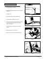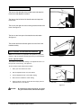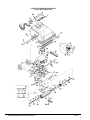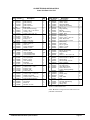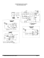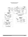
1
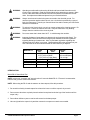
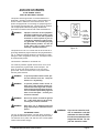
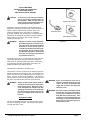
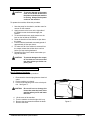
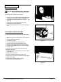
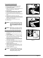
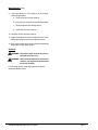
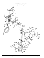
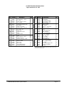
E
PB-12
Operator's
Manual
Power Brush
For Extraction
READ THIS BOOK
This book has important information for the use and safe operation of this machine. Failure to read
this book prior to operating or attempting any service or maintenance procedure to your Clarke
machine could result in injury to you or to other personnel; damage to the machine or to other property
could occur as well. You must have training in the operation of this machine before using it. If you
cannot read English, have this manual explained fully before attempting to operate this machine.
All directions given in this book are as seen from the operator’s position at the rear of the machine.
For new books write to: ALTO U.S. Inc., 2100 Highway 265, Springdale, Arkansas 72764.
Form No. 78010C
5/00
CLARKE TECHNOLOGY
Printed in the U.S.A.
Table of Contents
Operator Safety Instructions ........................................................................................................... 3
Introduction ..................................................................................................................................... 4
How To Assemble the Machine ....................................................................................................... 5
Machine Controls ............................................................................................................................ 7
How to Prepare The Machine for Operation .................................................................................... 7
How to Adjust the Brush ......................................................................................................... 7
How to Connect the Hoses ..................................................................................................... 8
How to Adjust the Handle ........................................................................................................ 8
Instruction for Connection to the Power Supply and Electrical Ground .................................. 9
How to Operate the Machine .......................................................................................................... 11
Maintenance of Machine ................................................................................................................. 11
How to Remove the Brush ................................................................................................. 11
How to Install The Brush .................................................................................................... 12
How to Remove the Brush Drive Belt ................................................................................ 12
How to Install the Brush Drive Belt .................................................................................... 13
How to do Maintenance After Each Use of Machine .......................................................... 13
Upper Unit Drawing ......................................................................................................................... 16
Parts List ............................................................................................................................ 17
Lower Unit Drawing ......................................................................................................................... 18
Parts List ............................................................................................................................ 19
Wiring Diagram 120V ...................................................................................................................... 20
Wiring Diagram 230V ...................................................................................................................... 21
CLARKE TECHNOLOGY PB-12 Operator's Manual
Page 2
OPERATOR SAFETY INSTRUCTIONS
WARNING
AVERTISSEMENT
ADVERTENCIA
DANGER:
Failure to read and observe all DANGER statements could result in
severe bodily injury or death. Read and observe all DANGER
statements found in your Owner's Manual and on your machine.
WARNING:
Failure to read and observe all WARNING statements could result in
injury to you or to other personnel; property damage could occur as
well. Read and observe all WARNING statements found in your
Owner's Manual and on your machine.
CAUTION:
Failure to read and observe all CAUTION statements could result in
damage to the machine or to other property. Read and observe all
CAUTION statements found in our Owner's Manual and on your
machine.
DANGER:
Failure to read the Owner's Manual prior to operating or attempting any service or
maintenance procedure to your machine could result in injury to you or to other
personnel; damage to the machine or to other property could occur as well. You
must have training in the operation of this machine before using it. If you or your
operator(s) cannot read English, have this manual explained fully before attempting
to operate this machine.
DANGER:
Operating a machine that is not completely or fully assembled could result in injury
or property damage. Do not operate this machine until it is completely assembled.
Inspect the machine carefully before operation.
DANGER:
Machines can cause an explosion when operated near flammable materials and
vapors. Do not use this machine with or near fuels, grain dust, solvents, thinners,
or other flammable materials.
DANGER:
Using a machine with a damaged power cord could result in an electrocution. Do
not use the machine if the power cord is damaged. To prevent damage to the
power cord, do not move this machine over the power cord. Always lift the power
cord over the machine. Do not use the electrical cord to move the machine.
DANGER:
Electrocution could occur if maintenance and repairs are performed on a unit that
is not disconnected from the power source. Disconnect the power supply before
attempting any maintenance or service.
DANGER:
Electrocution or fire could occur if the machine is used on a power circuit that
repeatedly trips or is undersized. Have a licensed electrician check the fuse,
circuit breaker or power supply, and/or contact your local Clarke distributor for
assistance.
WARNING:
Operating this machine from anywhere other than the back of the machine could result in
injury or damage. Operate this machine only from the rear.
WARNING:
Machines can topple over if guided over the edges of stairs or loading docks and cause
injury or damage. Stop and leave this machine only on a level surface. When you stop
the machine, put all switches into their "OFF" position.
WARNING:
Any alterations or modifications of this machine could result in damage to the machine or
injury to the operator or other bystanders. Alterations or modifications not authorized by
the manufacturer voids any and all warranties and liabilities.
CLARKE TECHNOLOGY PB-12 Operator's Manual
Page 3
WARNING:
Operating a machine without observing all labels and instructional information could
result in injury or damage. Read all machine labels before attempting to operate. Make
sure all of the labels and instructional information are attached or fastened to the machine. Get replacement labels and plates from your Clarke distributor.
WARNING:
Always use a three-wire electrical system connected to the electrical ground. For
maximum protection against electric shock, use a circuit that is protected by a ground
fault circuit interrupter. Consult your licensed electrician and/or contact your local Clarke
distributor for assistance.
WARNING:
To reduce risk of electric shock, use only on carpet moistened by cleaning process. Do
not immerse. Protect the machine from rain. Keep the machine in a dry building.
Always clean the machine with a clean dry cloth.
WARNING:
Do not use water that is hotter than 140°F. It could damage the machine.
WARNING:
Improper discharge of waste water may damage the environment and be illegal. The
United States Environmental Protection Agency has established certain regulations
regarding discharge of waste water. Also, city and state regulations regarding this
discharge may be in effect in your area. Understand and follow the regulations in your
area. Be aware of the environment hazards of chemicals that you dispose.
Model PB-12
Dimensions
Weight
Shipping Weight
Noise (dBA)
Vibration (m/s/s)
04016B
04017B
115V
230V
17.75" (45.1 cm) Long
16.75" (42.5 cm) Wide
8.78" (22.5 cm) High (Base)
60 lbs.
60 lbs.
66 lbs.
70 lbs.
04087A
230V
45 cm long
43 cm wide (base)
23 cm high
< 70
< 2.5
INTRODUCTION
Model PB-12 Power Brush Tool
NOTE: In this book, "machine" and "power brush tool" mean the Model PB-12. "Extractor" means another
machine that gives the solution and vacuum.
NOTE: When using the PB-12 and the extractor to clean carpets, follow this procedure.
1. Do not walk on freshly cleaned carpets for at least four hours or until the carpet is dry to touch.
2. Do not remove aluminum or plastic pieces that have been placed under the legs of the furniture until the
carpet is dry.
3. Do not allow children or pets to crawl or walk around on the damp carpet.
4. Vacuum right after the carpet is dry and then vacuum the carpet once a week or as needed.
CLARKE TECHNOLOGY PB-12 Operator's Manual
Page 4
How To Assemble The Machine
To assemble the machine, follow this procedure:
1. Put the machine on a bench.
2. Put the brush adjusting lever in the unlock position.
See figure 1
3. Lift the cover.
Figure 1
4. Remove the pivot pin from the plastic bag.
5. Put the handle in position. See figure 2
6. From the inside of the machine, slide the pivot pin
through the handle tube tongue and the main
frame. See figure 3.
7. Close the cover. Put the lever in the locking
position.
Figure 2
8. Install the cotter pin. See figure 4.
9. Remove the locking cam from the plastic bag.
Figure 3
Figure 4
CLARKE TECHNOLOGY PB-12 Operator's Manual
Page 5
How To Assemble The Machine (cont)
10. Remove the nut and one plain washer from the
locking cam. Leave one plain washer on the
locking cam. See figure 5
11. Raise the handle and align the holes.
See figure 6.
Figure 5
12. Insert the cam through the link arms and the
handle tube clamp. See figure 7.
13. Install the washer and the locking nut.
Figure 6
14. Install the solution hose around the outside of the
handle to the fitting on the handle tube.
See figure 8.
15. Install the vacuum hose. See figure 9.
Figure 7
Figure 9
CLARKE TECHNOLOGY PB-12 Operator's Manual
Figure 8
Page 6
THE CONTROLS
The lever on the right side of the handle starts and stops the
brush motor and applies the solution.
The lever on the left side of the handle starts and stops the
brush motor.
The lever on the right side of the housing raises and lowers the
brush. See figure 10.
Figure 10
The lever on the lower part of the handle locks the handle.
See figure 11.
The solution and brush indicator lights are on the front of the
handle assembly.
HOW TO PREPARE THE MACHINE FOR OPERATION
NOTE: For instructions for preparation and operation of your tank
extractor, read the operator's manual given with your tank extractor.
Figure 11
How To Adjust The Brush
The machine has seven brush settings. The adjustment lever is on
the right side of the housing. See figure 12.
To set the brush height, follow this procedure:
1.
Place your foot behind one wheel.
2.
Pull the adjustment lever out of the detent.
3.
Put the adjustment lever in the "HIGH" setting.
4.
Move the lever toward the "LOW" setting.
5.
When the brush comes in contact with the carpet, push the
adjustment lever in the detent.
1. The Lever
2. The Settings
Figure 12
CAUTION:
Be careful when cleaning long shag. The carpet
can go around the brush, and slow and stop the
CLARKE TECHNOLOGY PB-12 Operator's Manual
Page 7
How To Prepare The Machine For Operation (cont)
How to Connect the Hoses
The hoses for the solution and vacuum are provided with
the tank extractor.
Connect the vacuum hose to the hose connector on the
extractor and to the hose connector on the power brush
tool.
The solution hose has quick-disconnect couplings. To
connect the solution hose to the extractor, follow this
procedure:
1. Pull the knurled collar back.
Figure 13
2. Put the coupling over the fitting on the handle assembly.
3. Release the knurled collar.
See figure 13
How To Adjust The Handle
To adjust the handle, follow this procedure:
1. The locking lever is on the lower part of the handle tube.
Lift the lever with your foot.
2. Lower the handle to the best operating position.
NOTE: For best operation, raise the handle until the
wheels are just above the floor. Keep your back
straight.
Figure 14
3. Using your foot, push the locking lever down. See figure
CLARKE TECHNOLOGY PB-12 Operator's Manual
Page 8
120 VOLT, 50/60 CYCLE MACHINES
INSTRUCTIONS FOR CONNECTION
TO THE POWER SUPPLY
AND THE ELECTRICAL GROUND
This product must be grounded. If it should malfunction or
breakdown, grounding provides a path of least resistance for
electric current to reduce the risk of electric shock. This
product is equipped with a cord having an equipment-grounding conductor and grounding plug. The plug must be inserted
into an appropriate outlet that is properly installed and
grounded in accordance with all local codes and ordinances.
WARNING:
Improper connection of the equipmentgrounding conductor can result in a risk
of electric shock. Check with a qualified
electrician or service person if you are
in doubt as to whether the outlet is properly grounded. Do not modify the plug
provided with the product - if it will not
fit the outlet, have a proper outlet installed by a qualified electrician.
PLATE
SCREW
OUTLET
MUST BE
CONNECTED
TO THE
ELECTRICAL
GROUND
GROUND PIN
Figure 15
This product is for use on a nominal 120 volt circuit and has a
grounding attachment plug that looks like the plug illustrated in
Fig. 15. Make sure that the product is connected to an outlet
having the same configuration as the plug. No adaptor should
be used with this product.
This machine is intended for commerical use.
For maximum protection against electric shock, use a circuit
that is protected by a ground fault circuit interrupter. The
green (or green and yellow) conductor in the cord is the
ground wire. Never connect this wire to any terminal other
than the ground terminal.
WARNING:
To prevent possible electric shock, protect the machine from rain. Keep the
machine in a dry building.
WARNING:
To prevent possible electric shock, always use a 3-wire electrical system connected to the electrical ground. For maximum protection against electrical shock,
use a circuit that is protected by a ground
fault circuit interrupter. Consult your
electrical contractor.
WARNING:
Do not cut, remove or break the ground
pin. If the outlet does not fit the plug,
consult your electrical contractor.
WARNING:
Have worn, cut, or damaged cords and
plugs replaced by an authorized service
person.
WARNING:
EXTENSION CORDS
Use only an approved extension cord with three conductors, a
plug with three terminals, and a connector body with three holes.
The machine has a power cord with wire size 14 AWG (AWG
means American Wire Gauge).
CLARKE TECHNOLOGY PB-12 Operator's Manual
If you use an extension cord,
use an extension cord with
minimum wire size 14 AWG.
Do not use an extension cord
longer than 50 feet. Do not
join two extension cords.
Page 9
230 VOLT MACHINES
INSTRUCTIONS FOR CONNECTION
TO THE POWER SUPPLY
AND THE ELECTRICAL GROUND
CAUTION:
This machine will operate only on AC frequency and electrical voltage shown on
the nameplate. Make sure you have the
correct frequency and voltage before connecting the power cord to an outlet.
This product must be grounded. If it should malfunction or
breakdown, grounding provides a path of least resistance for
electric current to reduce the risk of electric shock. This
product is equipped with a cord having an equipmentgrounding conductor and grounding plug. The plug must be
inserted into an appropriate outlet that is properly installed
and grounded in accordance with all local codes and
ordinances. See figure 16
WARNING:
Improper connection of the equipmentgrounding conductor can result in a risk
of electric shock. Check with a qualified
electrician or service person if you are
in doubt as to whether the outlet is properly grounded. Do not modify the plug
provided with the product - if it will not fit
the outlet, have a proper outlet installed
by a qualified electrician.
PIN EARTHING CONTACT
EUROPEAN PLUG
SIDE EARTHING CONTACT
Figure 16
This product is for use on a nominal 230 volt circuit and has
a grounding attachment plug that looks like the plug illustrated in Fig. 16. Make sure that the product is connected to
an outlet having the same configuration as the plug. No
adaptor should be used with this product.
This machine is intended for commerical use.
This machine must be connected to the electrical ground to
protect the operator from electrical shock. The machine has a
power cord with two main conductors and one earthing conductor. Connect the plug to the receptacle. The green and
yellow conductor in the cord is the ground wire. Never connect
this wire to any terminal other than the ground terminal.
WARNING: Always use this machine with an AC threeconductor electrical system connected to
the electrical ground. Replace any worn,
cut or damaged cords. Replace any damaged plugs, receptacles, or connector bodies. Do not move the machine over an electrical cord. Always lift the cord over the
machine.
EXTENSION CORDS
Use only an approved extension cord with two main conductors and one earthing conductor. The machine has a power
cord with wire size 1.5mm2.
CLARKE TECHNOLOGY PB-12 Operator's Manual
WARNING: If you use an extension cord, use an
extension cord with minimum wire size
1.5mm2. Do not use an extension cord
longer then 15 meters. Do not join two
extension cords.
WARNING: Do not cut, remove or break the ground
terminal. Do not try to fit a three-terminal plug into a receptacle or connector
body that does not fit the plug. If the
receptacle or connector body does not
fit the plug, see your authorized Clarke
dealer to get an authorized person to
make the connection.
Page 10
HOW TO OPERATE THE MACHINE
CAUTION:
To prevent damage to the power
cord, do not let the brush touch
the power cord when the machine
is running. Always lift the power
cord over the machine.
To operate the machine, follow this procedure:
1. Start the pump for the solution, and the motor for
vacuum on the extractor.
2. Apply pressure to the lever on the right side of
the handle to start the brush and apply the
solution.
3. To start the brush motor, apply pressure to the
lever on the left side of the handle.
4. Raise the handle until the wheels are just above
the carpet.
5. Pull the machine backward at a steady speed of
approximately 30 feet per minute.
6. To make sure all of the solution is removed from
the carpet, release the solution lever one foot
before you stop moving backward.
7. Release the lever for the brush motor when you
stop the machine.
CAUTION:
To prevent damage to the carpet,
do not clean an area more than
two times unless you let the carpet dry first.
MAINTENANCE OF THE MACHINE
How To Remove The Brush
To remove the brush, follow this procedure:
1. Disconnect the electrical plug from the electrical
outlet.
2. Put the machine on a bench.
3. Put the brush adjusting lever in the unlock position. See figure 17.
CAUTION:
4.
5.
6.
7.
Be careful not to damage the
hoses that enter the back of the
machine when you lift and lower
the cover.
Lift the cover of the machine.
Turn the machine so that the right side is up.
Remove the two screws that fasten the brush.
Remove the brush.
CLARKE TECHNOLOGY PB-12 Operator's Manual
Figure 17
Page 11
MAINTENANCE (cont)
How To Install The brush
CAUTION: Keep all fadteners tight. Keep adjustments according to specifications.
To install the brush, follow this procedure:
1. Put the two pins on the brush housing plate in the
two holes in the brush end plate. See figure 18
2. Make sure the shaft assembly is in position. See
figure 19.
3. Install the two screws that fasten the brush.
4. Lower the cover if the machine.
5. Put the brush adjustment lever in the locking position.
Figure 18
How to Remove The Brush Drive Belt
To remove the brush drive belt, follow this procedure:
1. Disconnect the elctrical plug from the electrical outlet.
2. Put the machine on a bench.
3. Release the handle.
4. Turn the machine so the right side is up.
5. Loosen the four screws that hold the motor.
6. Slide the motor toward the front of the machine.
7. Put the brush adjusting lever in the unlock position.
8. Lift the cover.
9. Remove the two screws that fasten the brush.
10.Remove the brush.
11. Remove the three screws that hold the belt guard.
See figure 20.
12. Remove the belt guard.
13. Turn the machine so that the left side is up.
14. Remove the two pins from the brush housing plate.
15. Remove the plate.
16. Remove the bolt that holds the pulley.
17. Remove the pulley and the belt.
Figure 19
Figure 20
CLARKE TECHNOLOGY PB-12 Operator's Manual
Page 12
How to Install The Brush Drive Belt
To install the brush drive belt, follow this procedure:
1. Turn the machine so that the left side is up.
2. Put the belt on the pulley.
3. Make sure the spacer is in position between the outside frame and the pulley. See figure 21.
4. Install the pulley.
5. Install the bolt that holds the pulley. See figure 22.
6. Install the belt guard with the three holding screws.
7. Turn the machine so that the right side is up.
8. Install the brush with the two screws that hold the
brush.
9. Install the belt on the pulley on the motor.
10. Install the belt, slide the motor toward the back of the
machine. The tension of the belt is corrrect when the
belt is tight but not extended.
11. Tighten the four screws that hold the motor.
12. Close the cover.
Figure 21
WARNING: To prevent electrical shock, always
disconnect the electrical plug from
the electrical outlet before doing any
repair or maintenance to this machine.
WARNING: Maintenance and repairs must be
done by authorized personnel only.
Figure 22
After each use of the machine, follow this procedure:
1. Flush the solution system with clean water from
the extractor.
2. Disconnect the solution hose and the vacuum hose
from the machine.
3. Drain the solution system. To drain the solution
system, press the pin in the male connector. Apply
pressure to the brush and solution lever.
4. Disconnect the plug from the electrical outlet. For
storage, put the electrical cord around the cord hook
and the top of the handle.
5. Use a stick of wood approximately six inches long
to remove the carpet fibers and objects caught under the brush housing.
6. Wipe the machine with a dry cloth.
7. Check the objects in the vacuum opening. Use a
stick to remove any objects caught under the brush
housing. See figure 23
8. Check for leaks at all connections.
Figure 23
CAUTION: To prevent damage to the spray jet,
do not push a wire or other object
through the opening in the jet.
CLARKE TECHNOLOGY PB-12 Operator's Manual
Page 13
MAINTENANCE (cont)
9. Check the spray jet. If the spray jet is not working,
follow this procedure.
a. Remove the jet from the machine.
b.
Put the jet into a solution of ammonia and water.
c. Blow compressed air through the jet.
d. Install the jet on the machine.
10. Use a dry cloth to wipe the machine.
11. Apply a small amount of silicone lubricant to the quickdisconnect fittings on the brush adjustment lever.
12. Every three months, apply a drop of light oil to the handle
pivot and the axles of the wheels.
Electrical
WARNING: Electrical repairs must be done by authorized personnel only.
WARNING: After electrical repairs are done to the
machine, the machine must be tested
for electrical safety.
For electrical repairs, return this machine to a Clarke
Authorized Repair Center.
CLARKE TECHNOLOGY PB-12 Operator's Manual
Page 14
NOTES
CLARKE TECHNOLOGY PB-12 Operator's Manual
Page 15
CLARKE TECHNOLOGY Model PB-12
Upper Unit Drawing 5/00
CLARKE TECHNOLOGY PB-12 Operator's Manual
Page 16
CLARKE TECHNOLOGY Model PB-12
Upper Unit Parts List 5/00
Ref.
1
2
3
4
5
6
7u
8
9
10
11
Part No.
16702A
16700A
446760
962936
446860
37400A
35233A
437531
980603
962929
42231A
42214A
12
442060
13u 962954
14
768340
15
500241
16
61102A
17
911690
18
49000A
19
84807A
20
49603B
21
737140
22
727595
23
64325A
24
930005
25
449061
26u 35232A
Description
Lever Assembly - Switch
Lever Assembly - Switch
Pin - Pivot
Screw- #13-16 x ¾ HiLo
Plug - Rubber
Plug
Cover, Housing Switch, Rear
Strain Relief
Washer, #10 Shake
Screw, #10-32 x 3/8 Pn Hd
Cord, Power, 35'
Cord, Power, 35'
Clamp, Cord
Screw, 8-18 x 7/8 HiLo
Spring
Adapter, Switch
Bracket, Switch
Switch
Wire, Assembly, Jumper
Screw, 6-32 x 15/8
Harness Assembly, Handle
Nipple, Quick-Disconnect
Reducer, Brass
Hook, Cord
Rivet, 1/8 Pop
Tube, Handle Support
Housing, Switch Front
Qty.
1
1
2
9
1
1
1
1
2
2
1
1
1
2
2
2
1
2
2
2
1
1
1
1
2
1
1
Ref.
27
28
29
30
Part No.
925600
911933
73267B
44101A
44100A
31
920248
32
980645
33
440302
34
962891
35
980652
36
19300A
37
743381
38
442001
39
15600A
40
509240
41u 747553
42
920110
43
67400A
44
440301
45
980349
46
441301
47
925592
48
461404
49
925036
50
66500A
51
47711A
NI* 899254
Description
Pin, ¼ x 17/8
Terminal, Ring
Label, Switch Housing
Lamp Indicator - 220V
Lamp Indicator - 120V
Nut, 3/8 - 16 Lock
Washer, 3/8 Plain
Arm Link LH
Screw, 5/16 - 18 x 2.0 Hx
Washer, 5/16 Lock
Tube Assembly, Handle
Fitting
Clamp, Handle Tube
Hose, Assembly
Tongue, Handle Tube
Strain, Relief
Nut, 5/16 - 18 ESNA
Shaft, Link Arms
Arm, Link RH
Washer, Wear
Bolt, Locking Cam
Pin, ¼ x 1" Lg. Groove
Cam, complete Locking
Pin, Cotter
Pin, Handle, Tongue, Pivot
Terminal, .25 FIFQDC
Tie, Wire
Qty.
1
1
1
1
1
1
1
1
2
2
1
1
1
1
1
1
2
1
1
1
1
1
1
3
1
2
1
NOTE: u indicates a change has been made since the last
publication of this manual.
CLARKE TECHNOLOGY PB-12 Operator's Manual
Page 17
CLARKE TECHNOLOGY Model PB-12
Lower Unit Drawing 5/00
84
7
CLARKE TECHNOLOGY PB-12 Operator's Manual
Page 18
CLARKE TECHNOLOGY Model PB-12
Lower Unit Parts List 5/00
Ref.
1
2
3
4
5
6
7u
8
9u
10
11
12
13
14
15
16u
17
18
19
20
21
22
23
24
25
26
27
28
29
30
31
32
33
34
35
36
37
38
39
40
41
42
43
44
Part No.
35105B
635139
215104
215103
305160
NI
77376A
962957
352030
962098
925004
67101A
606640
31202A
930074
930124
34201A
67600A
628382
980646
612050
439760
15600A
59700A
59735A
57200A
81600A
53600A
15601B
50900A
67401A
877307
962954
761140
701130
63400B
962015
962968
980603
962929
696614
962557
920068
53601A*
36500B
Description
Hose Vac
Label, Warning
Label, Warning
Label, Caution
Label, Inspection
Label, Serial
Label, Clarke Technology
Screw, ¼-20 x ½ Pn St HiLo
Housing, Outer
Screw, ¼-20 x ¾ FL ST
Pin, 1/16 Cotter
Rod, Cam
Plate, Cam Rod
Bumper, 12"
Rivet, 1/8 Dia. Pop
Rivet, 3/16 x .59 Lg.
Gasket, Shoe 12"
Shoe, 12"
Spring, Rod Return
Washer, ¼ Plain
Clamp, Cam Rod
Wheel, 5" Dia.
Hose, Assembly
Valve, Solenoid 220V
Valve, Solenoid 120V
Pulley, Motor
Nut, ¼-20 Speed
Elbow, 1/8 St. 45
Hose Assembly
Belt Gear
Shaft, Wheel Axle
Ring, Snap
Screw, #10-16 x 1 HiLo
Bushing, Snap
Bushing, snap
Frame, Main 12"
Screw, #10-24 x 3/8 Pan Hd.
Screw, #10-24 x ½ Pan Hd.
Washer, #10 Shake
Screw, #10-32 x 3/8 Pan Hd.
Plate and Shaft Assembly
Screw, ¼-20 x ¾ Hx Hd.
Nut, #10-24
Elbow, 90°
Manifold, 12" Asm.
Qty.
Ref.
1
1
1
1
1
1
1
8
1
2
1
1
1
1
3
4
1
1
1
1
2
2
Ref
1
1
1
4
1
1
1
1
2
4
1
1
1
4
2
4
2
1
4
1
1*
1
45
46
47
48
49
50
51
52
53
54
55
56
57
58
59
60
61
62
63
64
65
66
67
68
69
70
71
72
73
74
75
76
77
78
68347A*
980195
743650
747650
740250
915012
467308
902567
747522
56253A*
60703A
34100A
962799
746654
962801
747851
696902
920256
980651
980202
748150
902658
747350
67800A
962324
48500A
962507
170637
954002
44643A
816181
920200
73225A
962268
79
80
81
82
83
84
NI
NI
NI
NI
980982
51809A*
53955A*
85328A*
56459A
60076A
911413
912064
16283A
722021
Part No.
Description
Tube, with/Caps
Washer, Wave
Guard, Thread
Seal, Brush Roller
Adapter, Brush Bearing
Key, 3/32 x ½
Ring, Retaining
Bearing
Race, Brush Bearing
Nozzle, Spray
Brush, 12"
Guard, Pulley
Screw, ¼-20 x 3/8 Soc. Hd.
Plate, Brush Drive
Screw, #10-24 x 1 Fit Hd.
Shield, Pulley
Pulley, Brush
Nut, 5/16 -18 Hex
Washer, 5/16 Plain
Washer, Wave
Sleeve, Bearing
Bearing, Brush Pulley
Ring, Retaining
Spacer
Screw, 5/16 -18 x 1½ Hx. Hd.
Tubing
Screw, #10-24 x 3/8 Rd. St.
Clamp, Wiring
Wire Assembly, Ground
Motor, 120/230V
Sleeving (included on 49603B)
Nut, #10-24 Hex
Label, Brush Adjust
Screw, Set 8-32 x 5/16
(comes w/pulley(57200A)
Washer
Clamp
Flange, Clamp
Screw
Strain, Relief
Plate
Wire, Nut
Terminal, Solenoid Ring
KIt, Literature
Clamp, Hose
Qty.
1*
1
1
1
1
1
1
1
1
3*
1
1
2
1
3
1
1
1
1
1
1
2
1
1
1
1
1
1
1
1
1
1
1
1
8
2*
2*
2*
1
1
2
1
1
1
*NOTE: Included with item # 44.
NOTE: u indicates a change has been made since the last
publication of this manual.
CLARKE TECHNOLOGY PB-12 Operator's Manual
Page 19
CLARKE TECHNOLOGY Model PB-12
120 Volt Wiring Diagram 4/95
CLARKE TECHNOLOGY PB-12 Operator's Manual
Page 20
CLARKE TECHNOLOGY Model PB-12
230 Volt Wiring Diagram 4/95
CLARKE TECHNOLOGY PB-12 Operator's Manual
Page 21
NOTES
ALTO® PRODUCT SUPPORT BRANCHES
U. S. A. Locations
HEAD OFFICE
European Locations
PRODUCTION FACILITIES
ALTO U.S. Inc., St. Louis, Missouri
16253 Swingley Ridge Road, Suite 200
Chesterfield, Missouri 63017-1725
PRODUCTION FACILITIES
ALTO U.S. Inc., Springdale, Arkansas
2100 Highway 265
Springdale, Arkansas 72764
(501) 750-1000
Customer Service - 1-800-253-0367
Technical Service - 1-800-356-7274
ALTO U.S. Inc., Bowling Green, Ohio 43402
1100 Haskins
SERVICE FACILITIES
ALTO U.S. Inc., Carlstadt, New Jersey 07072
150 Commerce Road
(201) 460-4774
ALTO U.S. Inc., Elk Grove, Illinois 60007
2280 Elmhurst Road
(847) 956-7900
ALTO U.S. Inc., Denver, Colorado 80204
1955 West 13th Ave.
(303) 623-4367
ALTO U.S. Inc., Houston, Texas 77040
7215 North Gessner Road
SALES AND SERVICE FACILITIES
ALTO U.S. Inc., Madison Heights, Michigan 48071-0158
29815 John R.
(810) 544-6300
ALTO U.S. Inc., Marietta, Georgia 30062
1355 West Oak Common Lane
(770) 973-5225
CLARKE TECHNOLOGY
AMERICAN SANDERS TECHNOLOGY
A.L. COOK TECHNOLOGY
Customer Service Headquarters and Factory
2100 Highway 265
Springdale, Arkansas 72764
(501) 750-1000
Technical Service
1-800-356-7274
ALTO Danmark A/S, Aalborg
Blytaekkervej 2
DK-9000 Aalborg
+45 72 18 21 00
ALTO Danmark A/S, Hadsund
Industrikvarteret
DK-9560 Hadsund
+45 72 18 21 00
SALES SUBSIDIARIES
ALTO Canada Ltd., Rexdale Ontario
24 Constellation Ct.
(416) 675-5830
ALTO Overseas Inc., Sydney (Australia)
1B/8 Resolution Drive
Caringbah NSW 2229
+61 2 9524 6122
ALTO Cleaning Systems Asia Pte Ltd., Singapore
No. 17 Link Road
Singapore 619034
+65 268 1006
ALTO Deutschland GmbH, Frondenberg (Germany)
Ardeyer Str. 15
D-58730 Frondenberg
+49 2373 754 200
ALTO Cleaning Systems (UK) Ltd., Penrith
Gilwilly Industrial Estate
Penrith
Cumbria CA11 9BN
+44 1768 868 995
ALTO France S.A. Strasbourg
B.P. 44, 4 Place d’Ostwald
F-67036 Strasbourg
Cedex 2
+33 3 8828 8400
ALTO Nederland B.V. Vianen
Stuartweg 4C
NL-4131 NJ Vianen
+31 347 324000
ALTO Sverige AB, Molndal (Sweden)
Aminogatan 18
Box 4029
S-431 04 Molndal
+46 31 706 73 00
ALTO Norge A/S, Oslo (Norway)
Bjornerudveien 24
N-1266
+47 2275 1770
CLARKE TECHNOLOGY WARRANTY
This Clarke Industrial/Commercial Product is warranted to be free from defects in materials and workmanship under normal use and service for a period of one year from the date of purchase, when operated
and maintained in accordance with Clarke's Maintenance and Operations instructions.
This warranty is extended only to the original purchaser for use of the product. It does not cover normal
wear parts such as electrical cable, rubber parts, hoses and motor brushes.
If difficulty develops with the product, you should:
(a). Contact the nearest authorized Clarke repair location or contact the Clarke Service Operations Department, 2100 Highway 265, Springdale, Arkansas 72764, for the nearest authorized Clarke repair location.
Only these locations are authorized to make repairs to the product under this warranty.
(b). Return the product to the nearest Clarke repair location. Transportation charges to and from the repair
location must be prepaid by the purchaser.
(c). Clarke will repair the product and or replace any defective parts without charge within a reasonable time
after receipt of the product.
Clarke's liability under this warranty is limited to repair of the product and/or replacement of parts and is
given to purchaser in lieu of all other remedies, including INCIDENTAL AND CONSEQUENTIAL DAMAGES.
THERE ARE NO EXPRESS WARRANTIES OTHER THAN THOSE SPECIFIED HEREIN. THERE ARE NO
WARRANTIES WHICH EXTEND BEYOND THE DESCRIPTION OF THE FACE HEREOF. NO WARRANTIES,
INCLUDING BUT NOT LIMITED TO WARRANTY OF MECHANTABILITY, SHALL BE IMPLIED. A warranty
registration card is provided with your Clarke product. Return the card to assist Clarke in providing the
performance you expect from your new floor machine.
ALTO U.S. INC., 2100 Highway 265, Springdale, Arkansas 72764.
CLARKE TECHNOLOGY reserves the right to make changes or improvements to its machine
without notice.
Always use genuine Clarke Parts for repair.
2100 Highway 265
Springdale, Arkansas, 72764