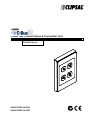
1
C-Bus Two Channel Infrared Transmitter Unit Installation Instructions 5034NIRT Series REGISTERED DESIGN REGISTERED PATENT Intelligent Building Series C-Bus Infrared Transmitter Installation Instructions Table of Contents Section..................................................................................................... Page 1.0 Product Range ........................................................................................3 2.0 Description ..............................................................................................3 3.0 Installation Instructions............................................................................4 3.1 Mounting Considerations...................................................................4 3.2 Infrared Emitter Leads .......................................................................4 3.3 Connection to the C-Bus Network .....................................................5 3.4 High Speed Serial Connection...........................................................6 4.0 Status Indicators......................................................................................7 4.1 Unit IR1 Indicator:..............................................................................7 4.2 C-Bus IR2 Indicator: ..........................................................................7 5.0 C-Bus System Clock ...............................................................................8 6.0 C-Bus Network Burden............................................................................8 7.0 C-Bus Power Requirements ....................................................................8 8.0 Power Up Load Status ............................................................................8 9.0 Power Surges and Short Circuit Conditions ............................................9 10.0 Megger Testing .......................................................................................9 11.0 Standards Complied................................................................................9 12.0 Programming Requirements.................................................................. 10 12.1 Programming C-Bus Operating Parameters .................................... 10 12.2 Programming Infrared Operating Parameters ................................. 10 12.3 Important Warning ........................................................................... 10 13.0 Electrical Specifications......................................................................... 11 14.0 Mechanical Specifications ..................................................................... 11 Copyright Notice Copyright 2002 Clipsal Integrated Systems Pty Ltd. All rights reserved. Trademarks • Clipsal is a registered trademark of Gerard Industries Pty Ltd. • C-Bus is a registered trademark of Clipsal Integrated Systems Pty Ltd • Intelligent Building Series is a registered trademark of Clipsal Integrated Systems Pty Ltd • CIRCA is a trademark of Clipsal Integrated Systems Pty Ltd All other logos and trademarks are the property of their respective owners. Disclaimer Clipsal Integrated Systems reserves the right to change specifications or designs described in this manual without notice and without obligation. © Copyright 2002 Clipsal Integrated Systems Pty Ltd Page 2 Intelligent Building Series C-Bus Infrared Transmitter Installation Instructions 1.0 Product Range 5034NIRT C-Bus Two Channel Infrared Transmitter Unit, 2000 Series C5034NIRT C-Bus Two Channel Infrared Transmitter Unit, C2000 Series SC5034NIRT C-Bus Two Channel Infrared Transmitter Unit, SC2000 Series SL5034NIRT C-Bus Two Channel Infrared Transmitter Unit, SL2000 Series E5034NIRT C-Bus Two Channel Infrared Transmitter Unit, E2000 Series S5034NIRT C-Bus Two Channel Infrared Transmitter Unit, S2000 Series 5100HSC High Speed Programming Cable (optional accessory) 2.0 Description The C-Bus Two Channel Infrared Transmitter Unit is a C-Bus Output Unit that allows control of third party devices over the medium of IR. The IR Unit is typically used for the control of audio visual equipment, such as televisions and video cassette recorders. Other infrared capable devices such as motorised blinds, air-conditioning and other products can also be controlled. The Unit can store an on-board library of up to 200 IR commands for control of these 3rd party devices (dependant on IR code length and protocol type). Specialised software tools are provided for programming the Unit (known as CIRCA software – C-Bus Infrared Commissioning Application). The CIRCA software allows the user to select IR codes to use, and to assign C-Bus events that trigger these IR codes to be transmitted. It allows the same configuration to be uploaded to multiple Units without requiring the creation of a new program for each Unit. A high speed programming cable is available for this device (catalogue number 5100HSC) to facilitate fast downloads to the Unit. This is especially useful where there are installations consisting of a large number of IR Units on a single Network. The IR codes can also be downloaded via the C-Bus Network. The C-Bus Infrared Transmitter does not support C-Bus2 Learn Mode. © Copyright 2002 Clipsal Integrated Systems Pty Ltd Page 3 Intelligent Building Series C-Bus Infrared Transmitter Installation Instructions 3.0 Installation Instructions A typical installation of the 5034NIRT C-Bus Infrared Transmitter is shown below: 3.1 Mounting Considerations • The E5034NIRT Unit is a British Standard Wall Plate, and may only be mounted using deep style wall boxes (Clipsal Catalogue Number E157). Do not use the shallow wall box (E157S). • All other units may be mounted using any of the standard Clipsal Australian Pattern Wall Boxes and other Mounting Accessories. • It is recommended that the Unit be mounted close to the floor, and discreetly located behind the control equipment. This will ensure a tidy installation. 3.2 Infrared Emitter Leads • The two IR output channels are connected by means of two 3.5mm mini audio mono sockets located on the front of the Unit. • The recommended emitter leads to use with this product are the single head (cat. no. 8050LD) or the dual head (cat. no. 8050/2LD) IR emitter leads. • The use of the recommended emitter leads will still allow the supplied remote for the device to function as the emitter head is transparent to IR. • Extension leads may be used on the emitter leads of up to 50m of category 5 or similar cable, such that the cable capacitance does not exceed 10nF. • The 3.5mm mini audio sockets are NOT isolated from C-Bus. Care must be taken to ensure that these connector housings are not grounded, or otherwise connected to an earth referenced voltage source (must be left floating). © Copyright 2002 Clipsal Integrated Systems Pty Ltd Page 4 Intelligent Building Series C-Bus Infrared Transmitter Installation Instructions 3.3 Connection to the C-Bus Network Installation requires connection to the unshielded twisted pair C-Bus Network Cable. The illustration below shows the recommended technique for cable termination giving the best electrical performance. It is required that Category 5 data cable is used, Clipsal catalogue number 5005C305B. The C-Bus Network connection is polarity sensitive, and is clearly marked on the rear of the Unit. C-Bus Connection Colour 5034NIRT Remote ON Remote ON C-Bus Neg (-) C-Bus Pos (+) C-Bus Neg (-) C-Bus Pos (+) Remote OFF Remote OFF Green/White Green Orange/White Blue Blue/White Orange Brown/White Brown Not Connected Not Connected C-Bus Neg (-) C-Bus Pos (+) C-Bus Neg (-) C-Bus Pos (+) Not Connected Not Connected * Note: The 5034NIRT does not have Remote Override (On/Off) functions, however these connections must be maintained for correct operation of these services across the C-Bus Network. © Copyright 2002 Clipsal Integrated Systems Pty Ltd Page 5 Intelligent Building Series C-Bus Infrared Transmitter Installation Instructions 3.4 High Speed Serial Connection The 5034NIRT Infrared Transmitter Unit requires programming and configuration. This can be achieved over the existing C-Bus Network cabling (via a PC Interface), however download times may be excessive (approx 15 minutes maximum for full configuration download). C-BUS NETWORK C-BUS 5034NIRT C-BUS IR TRANSMITTER Unit IR1 5500PC C-BUS PC INTERFACE C-Bus IR2 RS232 SERIAL COMMUNICATIONS CABLE PERSONAL COMPUTER (PC) CIRCA SOFTWARE A custom 4-pin connector is fitted to the side of the Unit for connecting the optional high-speed programming interface. This cable is available as an optional extra (catalogue number 5100HSC). Download times are significantly reduced using this method (2 minutes maximum). Please note that the connection is polarity sensitive. The four pin header should be connected such that the metal terminals are exposed when inserted from the rear, as shown in the drawing opposite. REAR VIEW C-BUS NETWORK 5034NIRT C-BUS IR TRANSMITTER Unit IR1 C-Bus IR2 5100HSC High Speed Serial Cable RS232 PERSONAL COMPUTER (PC) CIRCA SOFTWARE DO NOT LEAVE 5100HSC PERMANENTLY CONNECTED !!! © Copyright 2002 Clipsal Integrated Systems Pty Ltd Page 6 Intelligent Building Series C-Bus Infrared Transmitter Installation Instructions Note: Care must be taken when using the 5100HSC High Speed Serial Cable. Please note the following recommendations: • • • • The 5100HSC High Speed Serial Cable contains custom electronics (I2C), and is approximately 1 metre in length. Do not attempt to extend the length of this pre-terminated cable. If additional distance is required then use an RS232 extension lead (maximum recommended length 20m). The custom electronics imbedded within the 5100HSC are powered from the 5V rail provided by the PC serial port. When the 5100HSC is connected to the 5034NIRT Infrared Transmitter Unit the C-Bus Network is effectively grounded. This is generally not recommended, and can seriously affect the operation of the C-Bus Network. Do not leave the 5100HSC permanently connected. Special PC Communications Port Settings are not necessary (eg start bits, stop bits, baud, parity etc) as the CIRCA software will override these settings as required. 4.0 Status Indicators 4.1 Unit IR1 Indicator: If the Unit is powered and functional, the UNIT IR1 indicator will be illuminated and steady. This indicator may also flash to indicate C-Bus Network Communications traffic is being seen by the Unit. Indicator Status Meaning On Flashing Off Super-Bright Flashing* Power on and functional C-Bus communications in progress Unit has no power IR Transmission in progress – Channel One 4.2 C-Bus IR2 Indicator: This indicator shows the status of the C-Bus Network at this Unit. If sufficient network voltage and a valid C-Bus clock signal are present then the “OK” signal will be displayed (steady on). If a network is connected which has more current load than the power supplies can support, this indicator will flash to show a marginal network voltage. If there is no C-Bus Network Clock present then this indicator will not light. Indicator Status Meaning On Flashing Off C-Bus Network operational Insufficient power to support network No C-Bus Clock present or insufficient power to support network or C-Bus not connected (check terminations) IR Transmission in progress – Channel Two Super-Bright Flashing* * Note that this feature can be disabled using the CIRCA software. © Copyright 2002 Clipsal Integrated Systems Pty Ltd Page 7 Intelligent Building Series C-Bus Infrared Transmitter Installation Instructions 5.0 C-Bus System Clock The Infrared Transmitter Unit incorporates a software selectable C-Bus System Clock used for synchronising data communications waveforms on the C-Bus Network. This feature may be enabled using the C-Bus Installation Software. At least one C-Bus System Clock is required to be active for successful Network communications. No more than three units on any C-Bus Network should have active Clock circuitry, so this option should normally be disabled using the C-Bus Installation Software. 6.0 C-Bus Network Burden The Infrared Transmitter Unit incorporates a software selectable C-Bus Network Burden. This Network Burden may or may not be required to ensure correct operation of the C-Bus Network. If in doubt, consult the C-Bus Calculator – Network Design Verification Software Utility. The Network Burden can be enabled using the C-Bus Installation Software. CAUTION: The Graphical User Interface (GUI) software is designed to prevent the Burden from accidental selection. The following steps are required to correctly enable the Network Burden from the GUI: 1. 2. 3. 4. 5. 6. 7. Set the Unit Address to 001; Turn to the ‘Global Tab’ of the GUI; Select the Network Burden check box (cross inside box for ON); Click the OK button; Select ‘Save to Network’ and/or ‘Save to Database’; Click the OK button; then Repeat steps 3 and 4 within 20 seconds, to save your selection. To disable the Network Burden the same process applies except the Burden selection check box is cleared (remove cross). 7.0 C-Bus Power Requirements The 5034NIRT Infrared Transmitter Unit draws 32mA from the C-Bus Network. Adequate C-Bus Power Supply Units must be installed to support the connected devices. If in doubt, consult the C-Bus Calculator – Network Design Verification Software Utility. 8.0 Power Up Load Status The status of any infrared controlled device may be affected by mains power loss. For example: a television set which was on will lose power, and may not return to the On state after a mains power failure. In such a case the Infrared Transmitter may be used to turn the device back On, provided adequate means implemented to detect the power loss. © Copyright 2002 Clipsal Integrated Systems Pty Ltd Page 8 Intelligent Building Series C-Bus Infrared Transmitter Installation Instructions 9.0 Power Surges and Short Circuit Conditions The C-Bus Infrared Transmitter Unit is not directly connected to mains, however the mains voltage which is used to supply power to the C-Bus Network must be limited to the range specified. Each Unit incorporates transient protection circuitry and additional external power surge protection devices should be used to enhance system immunity to power surges. It is strongly recommended that overvoltage equipment such as the Clipsal 970 is installed at the switchboard. 10.0 Megger Testing Megger testing of an electrical installation that has C-Bus Units connected will not cause any damage to C-Bus Units. Since C-Bus Units contain electronic components, the installer should interpret megger readings with due regard to the nature of the circuit connection. Megger testing must never be performed on the C-Bus data cabling or terminals as it may degrade the performance of the Network. 11.0 Standards Complied Standard/Directive Title AS/NZS 3100:1997 General Requirements for Electrical Equipment IEC 742:1983; Requirements for Safety Extra Low Voltage © Copyright 2002 Clipsal Integrated Systems Pty Ltd Page 9 Intelligent Building Series C-Bus Infrared Transmitter Installation Instructions 12.0 Programming Requirements The 5034NIRT C-Bus Infrared Transmitter Unit requires programming in order to operate correctly: 12.1 Programming C-Bus Operating Parameters The C-Bus Infrared Transmitter Unit must be programmed to set a unique identification (Unit Address) and the mode of operation on the C-Bus Network. C-Bus Installation Software v2.3.0 (or higher). can be used to configure the: • • • • • Project Name Part Name Unit Address Clock (Enable/Disable) Network Burden (Enable/Disable) 12.2 Programming Infrared Operating Parameters Specialised software is provided to configure the infrared codes, and associate each to a C-Bus Network Variable (Group Address) so that it may be triggered. The software is known as the CIRCA Software (C-Bus Infrared Commissioning Application). To install the CIRCA software, simply insert the CD into the CD Drive of your personal computer or laptop and follow the on-screen prompts. The CD-ROM also contains Online Documentation. Please refer to the C-Bus Infrared Transmitter Programming Reference for further information relating to the programming of the Unit’s infrared operating parameters. Please note the following : • • • • • • • • • The Unit is programmed using the CIRCA Software. The Unit can be programmed over C-Bus. Alternatively, the Unit can be programmed using the optional high-speed download device (catalogue number 5100HSC). The Unit incorporates a 32kB memory, of which the maximum library size is 21.5kB for IR codes and protocol definitions. Actions (IR codes) can be triggered by C-Bus Group Addresses. Group Addresses may be switched, or may make use of discrete levels to initiate actions. The Unit supports up to 255 different actions. The Unit can be programmed to respond to C-Bus commands on up to 8 different C-Bus Applications. Special provision is made for infrared codes which require termination. The number of IR transmission frames can be set using the software. Please refer to the C-Bus Infrared Transmitter Programming Reference for further information. 12.3 Important Warning The use of any non C-Bus Software in conjunction with the hardware installation without the written consent of Clipsal Integrated Systems may void any warranties applicable to the hardware. © Copyright 2002 Clipsal Integrated Systems Pty Ltd Page 10 Intelligent Building Series 13.0 C-Bus Infrared Transmitter Installation Instructions Electrical Specifications Catalogue No. 5034NIRT C-Bus Supply Voltage Current Drawn AC Input Impedance Electrical Isolation Rating IR Ports IR Port Output Voltage IR Port Output Current IR Port Terminals IR Code Formats Supported IR Transmission Delay Communication Speed C-Bus Unit Type C-Bus System Clock C-Bus Network Burden Maximum Number of Units on a Single C-Bus Network C-Bus Input Terminals Shipping Weight Storage Temperature Range Operating Temperature Range Operating Humidity Range Dimensions (L x W x H) 14.0 15-36Vdc 32mA 50kΩ @ 1kHz 3.75kV RMS from C-Bus to mains 2 5Vdc (maximum) 20mA (maximum rated continuous output) 2 x 3.5mm mono mini audio jacks IR Carrier Frequencies 0 – 455kHz Pulsed IR Code Formats (carrier-less) 200ms (minimum delay between consecutive commands) ~ 300 bits/sec (via C-Bus) ~ 10 kbits/sec (via 5100HSC) PC_IRT2 Software Selectable Software Selectable 50 Units 0.2 – 1.5mm2 (24-16AWG) 90gm -10 – 60oC 0 – 45oC 10 – 95% RH 116 x 76 x 34mm (84mm Mounting Centres) 87 x 87 x 34mm (60mm Mounting Centres) Mechanical Specifications 32 77 Unit IR1 C-Bus IR2 117 All dimensions are in millimeters. No user serviceable parts inside. © Copyright 2002 Illustration shows Australian pattern 5034NIRT Only Clipsal Integrated Systems Pty Ltd Page 11 Further Information For further information about configuring this product and other C-Bus devices, please consult the documentation supplied. Further assistance can be obtained as follows: • C-Bus Manuals The 5000M/2 C-Bus Technical Manual provides a comprehensive and definitive guide to Clipsal C-Bus. Includes hardware and software specifications, product datasheets, system design and installation guides, and software overview with fully worked programming examples. • C-Bus Installation Software The 5000S/2 C-Bus Installation Software (includes 5000M/2 C-Bus Technical Manual) may be used to unlock the power and flexibility of Clipsal C-Bus. Unit operation may be completely customised to suit user requirements. Advanced control functions may be programmed. • C-Bus Installer Training Courses Contact your nearest Clipsal Integrated Systems Sales or Technical Support Officer and enquire about Clipsal C-Bus Installer Training and Certification Programs today !! • Technical Support and Troubleshooting For further assistance, please consult your nearest Clipsal Integrated Systems Sales Representative or Technical Support Officer. Technical Support Hotline Technical Support Email Sales Support Email Clipsal Integrated Systems Website 1 300 722 247 (Cost 25¢ per call, Australia Only) [email protected] [email protected] clipsal.com/cis Products of Clipsal Integrated Systems Pty Ltd ABN 15 089 444 931 Head Office 12 Park Terrace, Bowden South Australia 5007 International Phone +61 8 8269 0560 International Fax +61 8 8346 0845 Internet clipsal.com/cis E-Mail [email protected] 1036293