1
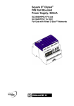
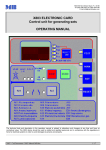
C-Bus DALI Gateway Installation Instructions 5502DAL REGISTERED PATENT Intelligent Building Series C-Bus DALI Gateway Installation Instructions Table of Contents Section ................................................................................................................. Page 1.0 Product Range....................................................................................................3 2.0 Description..........................................................................................................3 3.0 Capabilities .........................................................................................................3 4.0 C-Bus Indicators .................................................................................................3 4.1 Unit/Comms Indicator...................................................................................3 4.2 C-Bus Indicator:............................................................................................4 5.0 Wiring Instructions ..............................................................................................4 6.0 C-Bus System Clock...........................................................................................5 7.0 Connection to the C-Bus Network ......................................................................5 8.0 Network Burden ..................................................................................................6 9.0 C-Bus Side Programming Requirements............................................................6 10.0 Power Surges and Short Circuit Conditions .......................................................7 11.0 Megger Testing...................................................................................................7 12.0 Important Warning ..............................................................................................7 13.0 Standards Complied ...........................................................................................7 14.0 Product Specifications ........................................................................................7 15.0 Mechanical Specifications ..................................................................................7 Copyright Notice Copyright 2004 Clipsal Integrated Systems Pty Ltd. All rights reserved. Trademarks • Clipsal is a registered trademark of Clipsal Australia Pty Ltd. • C-Bus and C-Bus2 are registered trademarks of Clipsal Integrated Systems Pty Ltd. • Intelligent Building Series is a registered trademark of Clipsal Integrated Systems Pty Ltd. All other logos and trademarks are the property of their respective owners. Disclaimer Clipsal Integrated Systems reserves the right to change specifications or designs described in this manual without notice and without obligation. © Copyright 2004 Clipsal Integrated Systems Pty Ltd. Page 2 Intelligent Building Series C-Bus DALI Gateway Installation Instructions 1.0 Product Range 5502DAL C-Bus DALI Gateway 2.0 Description The 5502DAL C-Bus DALI Gateway unit is a C-Bus system support device designed to provide an isolated communications path between a C-Bus Network and two DALI Networks. For ease of installation the unit is DIN rail mounted, measuring 4M wide (1M = 17.5 +0.5/-0.0 mm). 3.0 Capabilities The DALI Gateway provides two C-Bus connections through the use of RJ45 connectors, allowing similar units to be quickly looped together. In normal operation, the unit draws 32mA from the C-Bus Network. The DALI Gateway is capable of generating C-Bus Clock signals. Each DALI Network can have up to 64 addressable DALI devices, such as fluorescent ballasts and low voltage transformers. The DALI Gateway does not have its own DALI addresses, i.e. it is transparent and is not "visible" for other DALI devices. The DALI Gateway provides two-way communication, i.e. selected C-Bus messages are routed to an appropriate DALI Network, and DALI lightning messages are routed to the C-Bus Network. The DALI Gateway constantly monitors both DALI Networks. It is capable of detecting and reporting to C-Bus faulty lamps in fluorescent ballasts or failed DALI units. DALI Networks are insulated from C-Bus and from each other by optocouplers. The insulation is capable of withstanding mains voltage. In the initial release the unit contains a pre-programmed C-Bus to DALI and DALI to C-Bus addressing structure. C-Bus Group Address DALI Address 0..3F 40..4F 50..5F 60 80..BF C0..CF D0..DF E0 DALI 1 short addresses 0..3F DALI 1 group addresses 0..F DALI 1 broadcast scenes 0..F DALI 1 broadcast DALI 2 short addresses 0..3F DALI 2 group addresses 0..F DALI 2 broadcast scenes 0..F DALI 2 broadcast SAFETY NOTE: DALI Networks are not rated as SELV despite of their low operating voltage of 16V. An assumption shall be made that a live mains voltage might occasionally appear on DALI wiring because of wiring errors or insulation faults. 4.0 C-Bus Indicators 4.1 Unit/Comms Indicator If the unit is powered and functional, the Unit/Comms indicator will be illuminated and steady. During data transfer on the RS232 port the Unit/Comms indicator will flash. Indicator Status Meaning On Flashing Power on and functional Data exchange in progress © Copyright 2004 Clipsal Integrated Systems Pty Ltd. Page 3 Intelligent Building Series C-Bus DALI Gateway Installation Instructions 4.2 C-Bus Indicator: This indicator shows the status of the C-Bus Network at this unit. If sufficient network voltage and a valid C-Bus Clock signal are present then the “OK” signal will be displayed (steady on). If a network is connected which has more current load than the power supplies can support, this indicator will flash to show a marginal network voltage. If there is no C-Bus Network Clock present this indicator will not light. Indicator Status Meaning On Flashing Off C-Bus Network operational Insufficient power to support network No C-Bus Clock present or insufficient power to support network or C-Bus not connected (check terminations). Lamp Ballast Mains 5.0 Wiring Instructions DALI 2 Network Mains Supply DALI Power Supply Mains Supply DALI Power Supply DALI 1 2 C-Bus2 C-Bus Category 5 Cable 5005C305B Ballast DALI Mains Lamp DALI 1 Network 2 8 1 7 4 6 5 3 CAT 5 Surface Box SMRJ88A5/1 DALI Gateway C-Bus Network C-Bus Patch Cord RJ5CB300PL NOTE: • The mutual twist of solid and dotted conductors of opposing coloured conductors. This ensures a good electrical termination, with favourable common mode noise characteristics. • A maximum of 64 DALI devices (max.) can be connected on a single DALI output channel. • A maximum of 50 DALI Gateways device can be connected on a single C-Bus Network • A maximum torque of 1.4Nm should be applied to the mains rated screw terminals. • Each DALI network must be interconnected with a maximum total wiring of 300m. • The wire used should be mains rated with double insulation and a minimum 1.5mmsq cross section. • Rubber bungs are supplied (3 off) for unused RJ45 connectors, to stop foreign bodies from entering the unit. Always ensure these bungs are installed when the unit is to be mounted inside a mains rated enclosure. © Copyright 2004 Clipsal Integrated Systems Pty Ltd. Page 4 Intelligent Building Series C-Bus DALI Gateway Installation Instructions Note: Clipsal Integrated Systems Pty Ltd does not manufacture DALI units, power supplies, commissioning software or any other product or service associated with DALI aside from the DALI Gateway itself, as described in this Installation Instruction. Check individual DALI component requirements. 6.0 C-Bus System Clock The DALI Gateway unit incorporates a software selectable C-Bus System Clock. The System Clock is used to synchronise data communications waveforms on a C-Bus Network. At least one active C-Bus System Clock is required on each C-Bus Network for successful communications. No more than three units on any C-Bus Network should have Clock circuitry enabled, so this option should normally be disabled using the C-Bus Installation Software. If a System Clock is required, it can be enabled from the ‘Global Tab’ on the Graphical User Interface (GUI) for the unit. 7.0 Connection to the C-Bus Network Installation requires connection to the unshielded twisted pair C-Bus Network Cable. The illustration following, shows the recommended technique for cable termination giving the best electrical performance. It is required that Category 5 data cable is used, Clipsal catalogue number 5005C305B. RJ Pin 1 2 3 4 5 6 7 8 C-Bus Connection Colour Remote ON * Remote ON * C-Bus Neg (-) C-Bus Pos (+) C-Bus Neg (-) C-Bus Pos (+) Remote OFF * Remote OFF * Green/White Green Orange/White Blue Blue/White Orange Brown/White Brown The DALI Gateway does have Remote Override (ON/OFF) functions. If both Remote ON wires are shorted together then it causes 5502DAL C-Bus DALI Gateway to issue a global message "Direct Arc Power 100%" to both DALI networks. If both Remote OFF wires are shorted together then it causes 5502DAL C-Bus DALI Gateway to issue a global message "Indirect Arc Power OFF" to both DALI networks. Remote ON has higher priority that Remote OFF, e.g. when both signals are activated the last command to both DALI networks will be "Direct Arc Power 100%". © Copyright 2004 Clipsal Integrated Systems Pty Ltd. Page 5 Intelligent Building Series C-Bus DALI Gateway Installation Instructions 8.0 Network Burden The DALI Gateway product incorporates a software selectable Network Burden. The Network Burden can be enabled using the C-Bus Installation Software. A Network Burden may or may not be required to ensure correct operation of the C-Bus Network. If in doubt, consult the C-Bus Calculator (Network Design Verification Software Utility) before proceeding with the hardware installation. CAUTION: The Graphical User Interface (GUI) software is designed to prevent the Burden from accidental selection. The following steps are required to correctly enable the Network Burden from the GUI: 1. 2. 3. 4. 5. 6. 7. Set the Unit Address to ‘001’; Turn to the ‘Global Tab’ of the GUI; Select the Network Burden check box (cross inside box for ON); Click the OK button; Select ‘Save to Network’ and/or ‘Save to Database’; Click the OK button; then Repeat steps 3 and 4 within 20 seconds, to save your selection. To disable the Network Burden the same process applies except the Burden selection check box is cleared (remove cross). Important Note: Always disable all 5100PC Interface Network Burdens before installing C-Bus DIN range products, which include a power supply (non “P” suffix versions). If a burden is required, use the built-in burden on the DIN Rail unit only. 9.0 C-Bus Side Programming Requirements The DALI Gateway product incorporates a C-Bus PC Interface Module for communications to the C-Bus Network. Programming of the C-Bus side of the Network Interface can be done in the same manner as programming a standard PC Interface. The DALI Gateway must be programmed to set a unique identification (Unit Address) and mode of operation on the C-Bus network. The C-Bus Installation Software can be used to configure all operational parameters. The DALI Gateway can be programmed using 5000S/2 C-Bus Installation Software v2.1.3 (or higher). The latest C-Bus Service Pack is a software plug-in designed to upgrade your existing C-Bus Installation Software v2.0 to the current build standard. Many new features and enhancements are added, including programming support for latest release C-Bus products. The latest C-Bus Service Pack is available for download from the Clipsal Integrated Systems Web Site ‘www.Clipsal.com/cis’. If web access is not available, simply complete the software coupon included. Forward the coupon to us and we will mail a CD-ROM containing the Service Pack to you. For further information about programming this and other C-Bus units, please refer to the C-Bus Technical Manual (5000S/2, 5000M/2). © Copyright 2004 Clipsal Integrated Systems Pty Ltd. Page 6 Intelligent Building Series 10.0 C-Bus DALI Gateway Installation Instructions Power Surges and Short Circuit Conditions The 5502DAL C-Bus DALI Gateway is not directly connected to the mains, however voltage surges applied to the AC/DC input should be avoided. Each unit incorporates transient protection circuitry, but additional external power surge protection devices should be used to enhance system immunity to power surges. It is strongly recommended that overvoltage equipment such as the Clipsal 970 be installed at the switchboard. 11.0 Megger Testing Megger testing must never be performed on the C-Bus data cabling or terminals as it may degrade the performance of the Network. Megger testing of mains wiring of an electrical installation that has C-Bus Units connected will not cause any damage to C-Bus Units. Since C-Bus Units contain electronic components, the installer should interpret megger readings with due regard to the nature of the circuit connection. 12.0 Important Warning The use of any non C-Bus Software in conjunction with the hardware installation without the consent of Clipsal Integrated Systems Pty Ltd. may void any warranties applicable to the hardware. 13.0 Standards Complied Standard/Directive Title AS/NZS 3548 Limits and Methods of Measurement of Radio Interference of Information Technology Equipment General Emission IEC 61000-6-3 14.0 Product Specifications Catalogue No. 5502DAL Series C-Bus Input Voltage C-Bus Current Drawn 15 – 36VDC 32 mA C-Bus Side Terminal RJ45 Connectors (2 off) DALI Side Terminals Screw terminals Max Devices Connected to C-Bus Network 50 Operating Temperature Range 0 - 450C Operating Humidity Range 10 - 95% RH Weight 130g Dimensions 72 x 85 x 65 (L x W x D in millimeters) 15.0 Mechanical Specifications All dimensions are in millimeters. No user serviceable parts inside. © Copyright 2004 Clipsal Integrated Systems Pty Ltd. Page 7 Further Information For further information about configuring this product and other C-Bus devices, please consult the documentation supplied. Further assistance can be obtained as follows: • C-Bus Manuals The 5000M/2 C-Bus Technical Manual provides a comprehensive and definitive guide to Clipsal C-Bus. Includes hardware and software specifications, product datasheets, system design and installation guides, and software overview with fully worked programming examples. • C-Bus Installation Software The 5000S/2 C-Bus Installation Software (includes 5000M/2 C-Bus Technical Manual) may be used to unlock the power and flexibility of Clipsal C-Bus. Unit operation may be completely customised to suit user requirements. Advanced control functions may be programmed. • C-Bus Installer Training Courses Contact your nearest Clipsal Integrated Systems Sales or Technical Support Officer and enquire about Clipsal C-Bus Installer Training and Certification Programs today !! • Technical Support and Troubleshooting For further assistance, please consult your nearest Clipsal Integrated Systems Sales Representative or Technical Support Officer. Technical Support Hotline Technical Support Email Sales Support Email Clipsal Integrated Systems Website 1 300 722 247 (Cost 25¢ per call, Australia Only) [email protected] [email protected] clipsal.com/cis Products of Clipsal Integrated Systems Pty Ltd ABN 15 089 444 931 Head Office 12 Park Terrace, Bowden South Australia 5007 International Phone +61 8 8440 0500 International Fax +61 8 8346 0845 Internet clipsal.com/cis E-Mail [email protected] 1036459