1
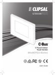
C-Touch Spectrum Colour Touchscreen
C-5000CT2 Series
Installation Instructions
C-Bus C-Touch Spectrum Colour Touchscreen
Installation Instructions
Contents
1
2
3
4
5
6
7
8
9
10
11
Product Range
Important Notes
Description
Installation
4.1
Location
4.2
Multiple Units
Mounting Instructions
5.1
Mounting in Stud Walls
5.2
Wall Box
5.3
Desktop Mounting
5.4
Attaching the Wall Mount Unit's Fascia
Wiring Details
6.1
C-Bus Network Connection
6.2
RS-232 Connection
C-Bus Requirements
Unit Reset
Specifications
Standards Complied
Two-Year Warranty
3
5
5
8
8
10
11
11
12
13
14
15
15
17
18
19
20
22
23
C-Bus and Clipsal are registered trademarks of Schneider Electric.
C-Touch and C-Touch Spectrum are trademarks of Schneider Electric
Saturn and Neo are trademarks of Schneider Electric.
All other trademarks are the property of their respective owners.
The information in this manual is provided in good faith. Schneider Electric has
endeavoured to ensure the relevance and accuracy of the information, but assumes
no responsibility for any loss incurred as a result of its use. Schneider Electric does
not warrant that the information is fit for any particular purpose, nor does it endorse
its use in applications that are critical to the health or life of any human being.
Schneider Electric reserves the right to update the information at any time without
notice.
December 2009
2
C-Bus C-Touch Spectrum Colour Touchscreen
1
Installation Instructions
Product Range
C-Touch Spectrum Wall Mounted Colour Touchscreen
Catalogue Number
US models are in
brackets ()
Description
C-SC5000CT2-WE
Touchscreen, wall mount, plastic surround, white
C-SC5000CT2-BK
Touchscreen, wall mount, plastic surround, black
C-SC5000CT2-CM
Touchscreen, wall mount, plastic surround, cream
C-5080CT2-GF
Touchscreen, wall mount, Saturn surround, white
C-5080CT2-3
Touchscreen, wall mount, Saturn surround, cream
C-5080CT2-7
Touchscreen, wall mount, Saturn surround, mid-brown
C-5080CT2-6
Touchscreen, wall mount, Saturn surround, black
C-5050CT2-GB
Touchscreen, wall mount, Neo surround, battleship
grey/brushed aluminium
C-5050CT2-WE
Touchscreen, wall mount, Neo surround, white
C-5050CT2-BK
Touchscreen, wall mount, Neo surround, black
C-5050CT2-28
Touchscreen, wall mount, Neo surround, white/ brushed
aluminium
C-BS5000CT2
Touchscreen, wall mount, brushed stainless steel
surround
C-BB5000CT2
Touchscreen, wall mount, polished brass surround
C-SC5000CTL2-WE
Touchscreen, wall mount, c/w Logic Engine, plastic
surround, white
C-SC5000CTL2-BK
Touchscreen, wall mount, c/w Logic Engine, plastic
surround, black
C-SC5000CTL2-CM
(SLC5000CTL2CM)
Touchscreen, wall mount, c/w Logic Engine, plastic
surround, cream
C-5080CTL2-GF
(SLC5080CTL2WE)
Touchscreen, wall mount, c/w Logic Engine, Saturn
surround, white
C-5080CTL2-3
(SLC5080CTL2CM)
Touchscreen, wall mount, c/w Logic Engine, Saturn
surround, cream
C-5080CTL2-7
(SLC5080CTL2BR)
Touchscreen, wall mount, c/w Logic Engine, Saturn
surround, mid-brown
C-5080CTL2-6
(SLC5080CTL2BK)
Touchscreen, wall mount, c/w Logic Engine, Saturn
surround, black
C-5050CTL2-GB
(SLC5050CTL2GB)
Touchscreen, wall mount, c/w Logic Engine, Neo
surround, battleship grey/brushed aluminium
3
C-Bus C-Touch Spectrum Colour Touchscreen
Installation Instructions
C-5050CTL2-WE
(SLC5050CTL2WE)
Touchscreen, wall mount, c/w Logic Engine, Neo
surround, white
C-5050CTL2-BK
(SLC5050CTL2BK)
Touchscreen, wall mount, c/w Logic Engine, Neo
surround, black
C-5050CTL2-28
Touchscreen, wall mount, c/w Logic Engine, Neo
surround, white/ brushed aluminium
C-BS5000CTL2
(SLCBS5000CTL2)
Touchscreen, wall mount, c/w Logic Engine, brushed
stainless steel surround
C-BB5000CTL2
(SLCBB5000CTL2)
Touchscreen, wall mount, c/w Logic Engine, polished
brass surround
Wall box
5000CT2WB
Infrared remote
5035TX2
RS-232 cable
5000CT2RS232
Table 1. Wall Mount Touchscreen product range
Note:
Wall units are shipped with a USB cable, a stylus and a parts kit.
C-Touch Spectrum Desktop Colour Touchscreen
Product
Fascia Colour
White
C-Bus
C-Touch Spectrum
Colour Desktop
Touchscreen
Grey
Black
Logic
Engine
Catalogue
Number
No
C-5000CTD2-WE
(SLC5000CTD2WE)
Yes
C-5000CTDL2-WE
No
C-5000CTD2-GY
Yes
C-5000CTDL2-GY
No
C-5000CTD2-BK
(SLC5000CTD2BK)
Yes
C-5000CTDL2-BK
Infrared
Remote Control
—
—
5035TX2
RS-232 Cable
—
—
5000CT2RS232
Table 2. Desktop Touchscreen product range
Note:
4
Desktop units include a curly C-Bus cable with two RJ45 connectors.
C-Bus C-Touch Spectrum Colour Touchscreen
2
Installation Instructions
Important Notes
Be aware of the following information for installation:
•
The C-Touch Spectrum Touchscreen is for indoor use only.
•
The touchscreen is never connected directly to mains building power
and does not require building power for its operation.
•
Using any non-C-Bus software with C-Bus hardware without the written
consent of Clipsal may void any hardware warranties.
•
Changes or modifications not expressly approved by Clipsal could void
the user’s authority to operate the equipment (under FCC rules).
•
To comply with EMC regulations the included ferrite filter must be fitted
to the C-Bus cable connected to the unit.
•
Do not Megger test the touchscreen units or the C-Bus network cables.
3
Description
The C-Bus C-Touch Spectrum Colour Touchscreen provides sophisticated
control of an entire C-Bus system from one location. Using the appropriate
software, you can:
•
Configure the screens for convenience of use.
•
Control devices and scenes.
•
By using C-Bus and the logic engine interface, you can use schedules
and timer control for lighting, HVAC, shutters and blinds telephony and
third-party devices
•
Configure an audible alarm.
5
C-Bus C-Touch Spectrum Colour Touchscreen
Installation Instructions
Features and Capabilities
The C-Touch Spectrum Colour Touchscreen is available in wall-mounted or
desktop configuration in a variety of colours and fascia styles. A wall box is
available for wall mounting. The desktop touchscreen can be permanently
attached to a shelf or counter top. The touchscreen includes an IR window
for remote control interface using a hand held C-Bus remote control.
To program the touchscreen a PC is connected to the USB interface. Clipsal
configuration software is downloaded from the Web. Projects are created
using PICED software and then transferred to the memory in the
touchscreen. The latest versions of software can be downloaded from the
Internet.
Units with a logic engine use an RS-232 connection to interface with thirdparty devices.
The touchscreen is powered by the C-Bus network and requires no mains
connection or power pack. The touchscreen has a real-time clock. For your
convenience, the internal CPU automatically controls the contrast and
brightness of the LCD screen.
The CPU also controls the brightness of the white LED backlight. A
proximity sensor turns on the backlight as you approach. This feature can
be switched off, if not desired.
By setting access levels and passwords, you can set up the touchscreen to
restrict access to touchscreen functions.
Notes:
•
The desktop touchscreen cable connections are located at the bottom of the
base.
•
The RS-232 connector on non-logic engine models has no function.
•
The wall mounted touchscreen's USB connector is behind the front fascia.
•
The C-Bus hand held remote control is not included with the touchscreen.
Figure 1 and Figure 2 show the connection points for the C-Bus network
cable, USB jack and the RS-232 logic engine port.
6
C-Bus C-Touch Spectrum Colour Touchscreen
Installation Instructions
Figure 1. Wall Mount touchscreen connection points
Figure 2. Desktop Touchscreen connection points
Note that the RS-232 connector is present on all units. On non-logic engine
units this connector has no function.
7
C-Bus C-Touch Spectrum Colour Touchscreen
4
Installation Instructions
Installation
When installing the touchscreen be careful not to scratch or otherwise
damage the plastic parts. Do not wipe the LCD screen with anything other
than a clean soft cloth. Refer to the User's Guide for care instructions.
4.1
Location
It is important to select the right location to install the C-Bus C-Touch
Spectrum Colour Touchscreen. Follow these guidelines when choosing a
location for the unit:
•
The touchscreen is designed for indoor use only.
•
Do not install the touchscreen where it will be exposed to:
o
Dripping or splashing liquids
o
Direct sunlight or a source of heat
o
High humidity or condensation
•
The screen has a typical viewing angle of 50° to the left and right, 70°
up and 40° down. Take this into account when choosing the mounting
height. The desktop touchscreen has a tilting front. Refer to Figures 3
and 4.
•
Provide easy access to the unit for switching lights and selecting
scenes.
•
Provide a clear area in front of the touchscreen for reception of infrared
signals from a remote control.
•
Do not mount opposite windows or other sources of bright light, as the
reflections make viewing difficult.
8
C-Bus C-Touch Spectrum Colour Touchscreen
Installation Instructions
Figure 3. Wall Mounted touchscreen unit’s viewing angles
Figure 4. Desktop unit's angle of tilt
9
C-Bus C-Touch Spectrum Colour Touchscreen
4.2
Installation Instructions
Multiple Units
Multiple touchscreens can be installed on a C-Bus network. These units
may be programmed to operate cooperatively or independently of each
other. Take care not to mount units where a single IR remote control
transmission can be received by multiple. Otherwise, multiple units may
trigger a scene, with unpredictable results.
Figure 5. Take care not to overlap IR transmission/reception zones
10
C-Bus C-Touch Spectrum Colour Touchscreen
5
Installation Instructions
Mounting Instructions
The wall-mounted units can be installed in stud/plasterboard walls (such as
timber frame internal walls) using the built-in mounting flaps, or in solid walls
(such as brick or stone) or stud walls using a wall box. The desktop unit is
placed on a solid flat surface and can be permanently attached to a shelf or
counter.
5.1
Mounting in Stud Walls
Caution
To avoid damage to the mounting hardware and to the plasterboard, do not
over tighten the mounting screws.
To install a wall-mounted unit in a stud/plasterboard wall:
1. Cut an appropriately sized hole using the provided template. Ensure you
leave sufficient clearance from studs and other obstructions.
2. Remove the green screw-terminal connector and wire to C-Bus.
3. Plug the connectors into the unit (C-Bus and RS-232 if used) and place
the touchscreen in the wall.
4. Tighten the four mounting screws to rotate and tighten the mounting
flaps.
Figure 6. Tighten the screws and the mounting flaps rotate and clamp the wall
11
C-Bus C-Touch Spectrum Colour Touchscreen
5.2
Installation Instructions
Wall Box
The Wall Box (catalogue number 5000CT2WB) for the C-Touch Spectrum
Touchscreen lets you mount the unit within a solid wall construction such as
brick or stone. The wall box (see Figure 7) may also be used to mount a unit
in timber or metal-framed stud walls.
Figure 7. The wall box for use with stud/plasterboard walls.
To mount the touchscreen using the wall box:
1. Prepare a hole in the wall or place the wall box against a beam of the
wall frame (in stud walls).
2. Fix the wall box into the wall or frame, in an appropriate manner.
3. Feed the cable(s) through to the wall box.
4. Remove the green plastic connector and wire to C-Bus.
5. Remove the four mounting flaps and fixing screws from the touchscreen
(these are not required).
6. Insert the screws provided in the parts pack through the holes identified
in Figure 8.
7. Hold the touchscreen up to the wall box and plug the cables into the
connectors (C-Bus and RS-232 if used).
8. Tighten the screws to fix the touchscreen to the wall box.
12
C-Bus C-Touch Spectrum Colour Touchscreen
Installation Instructions
Figure 8. Remove the flaps and insert the screws into the identified holes
5.3
Desktop Mounting
The desktop model can be permanently attached to a counter top or table.
Remove the base cover using a flat blade screwdriver.
Figure 9. Mounting the Desktop Touchscreen
13
C-Bus C-Touch Spectrum Colour Touchscreen
5.4
Installation Instructions
Attaching the Wall Mount Unit's Fascia
It is highly recommended that you remove power from the touchscreen
before removing or attaching the fascia.
To attach the Wall Mount unit's fascia:
1. Position the fascia over the touchscreen, with the indicator window on
the right hand side. Press the top of the fascia against the wall just
above the touchscreen.
2. Slide the fascia down over the top of the touchscreen so it clips to the
chassis.
3. Press the bottom of the fascia, on each side, so it snaps into place.
2
3
Figure 10. Attaching the fascia (Wall Mounted Touchscreen)
To remove the fascia, insert the head of a flat head screwdriver into each
slot at the base of the fascia, and twist.
14
C-Bus C-Touch Spectrum Colour Touchscreen
6
Installation Instructions
Wiring Details
Two connectors are provided on the rear of the wall-mounted units. These
are the C-Bus and RS-232. The USB programming connector is located on
the front of the unit, behind the fascia.
The C-Bus and RS-232 connections for the desktop touchscreen are
located on the bottom of the base piece. The USB programming connector
is located on the right hand side of the screen.
6.1
C-Bus Network Connection
The connection to the C-Bus network on the wall mount touchscreen is
made via the removable screw-type connector on the rear of the unit. The
desktop unit has an RJ45 socket located on the bottom of the base.
Note:
The desktop version is supplied with a curly cord that has an RJ45 plug at
each end.
Use Cat-5 Unshielded Twisted Pair (UTP) C-Bus cable, and an appropriately
wired 4-pin plastic plug or RJ45 connector. The use of bootlace ferrules
(crimps) for screw terminals is recommended for a reliable connection.
C-Bus cable conductor assignments are provided in Table 3. The Clipsal
catalogue numbers for the C-Bus Cat-5 UTP cables are 5005C305B (solid
conductors) and 5005C305BST (stranded conductors).
Terminal
C-Bus Connection
Colour
—
C-Bus Negative (—)
blue & white
+
C-Bus Positive (+)
blue
—
C-Bus Negative (—)
orange & white
+
C-Bus Positive (+)
orange
Remote OFF
brown + brown & white
Remote ON
green + green & white
C-Bus
Not connected
Table 3. C-Bus network cable wire colour assignments
15
C-Bus C-Touch Spectrum Colour Touchscreen
Installation Instructions
Figure 11. C-Bus network cable connections
The touchscreen does not have Remote Override functions (Remote
ON/Remote OFF). However, if more than one C-Bus cable is connected to
the unit, the Remote Override connections should be maintained across the
cables to ensure correct operation of these services.
Install a ferrite filter on the C-Bus network cable between the touchscreen
and the nearest connection to the network to apply an additional level of
filtering for compliance with EMC regulations.
Figure 12. Ferrite filter placement on the C-Bus network cable
16
C-Bus C-Touch Spectrum Colour Touchscreen
6.2
Installation Instructions
RS-232 Connection
The RS-232 serial port connection is useable on logic engine models only.
The connection point is a 3.5 mm stereo jack with pinouts for RxD, TxD and
GND. A special RS-232 cable is available (Clipsal cat. number
5000CT2RS232).
Pinouts are provided in Table 4. The RS-232 port allows you to connect
external devices to the unit, such as security and control equipment.
Note:
If using the RS-232 port to connect to external devices, ensure that
you use a suitable shielded data cable. Cable length should be
limited to 15 metres for communication at up to 19,200 bps, or
7.5 metres at 38,400 bps.
Pin
Name
Description
Tip
TxD
Transmit Data
Ring
RxD
Receive Data
Sleeve
GND
Ground
Table 4. RS-232 pinouts for the Logic Engine connection
17
C-Bus C-Touch Spectrum Colour Touchscreen
7
Installation Instructions
C-Bus Requirements
The C-Bus C-Touch Spectrum Colour Touchscreen must be programmed
with a unique unit address. This is accomplished using C-Bus Toolkit
software, available at the Clipsal Integrated Systems (CIS) web site,
http://www.clipsal.com/cis. Go to the Technical section and select
'Downloads.'
The touchscreen must be configured with a software project customised for
a particular C-Bus installation. The project is produced using the
Programming Interface for C-Bus Embedded Devices (PICED) software. The
PICED software is available from the Downloads location cited previously.
After creating a project using the PICED software, connect the USB
programming cable from the touchscreen to your PC. Use the ‘Transfer
Project to unit’ option to upload the project to the touchscreen. This option
is located in the PICED software Transfer menu.
The touchscreen configuration files should be saved to disk and kept in an
archive at your premises. It is also recommended to give a copy to the
customer.
C-Bus Power
The touchscreen draws its operating power from the C-Bus network. The
unit does not supply power to the C-Bus network. The touchscreen is never
connected to building power.
Adequate C-Bus network power supply units must be installed to support
connected devices. The Network window of a C-Bus Toolkit project
provides a summary of a C-Bus network according to the units added to the
Database. This can be helpful in determining the power supply requirements
of a particular network.
C-Bus Clock
The touchscreen incorporates a software selectable C-Bus system network
clock. The clock is used to synchronise data communication over a C-Bus
network. The touchscreen’s C-Bus system clock is enabled as default. Its
state can be changed from the unit’s 'Global' tab in C-Bus Toolkit.
18
C-Bus C-Touch Spectrum Colour Touchscreen
8
Installation Instructions
Unit Reset
The wall mount touchscreen has a button that can be used to recover the
unit if the firmware becomes corrupted. The Unit Reset button is located on
the front of the unit, under the fascia, immediately above the USB
connector. The button is pressed when the unit is powered, using a pin or
paper clip to break the sticker through the white dot.
Do not use this button if the unit is operating normally. If you have questions
regarding the use of the Unit Reset button, contact Technical Support.
Caution
Pressing the Unit Reset button will erase ALL firmware and project data in
the unit and reset it.
After pressing the Unit Reset, the touchscreen ceases operation and
displays a blank (black) screen. The blue power LED remains on. Firmware
can then be reloaded using the ‘Recover C-Touch 2’ option from the
Transfer menu in PICED.
19
C-Bus C-Touch Spectrum Colour Touchscreen
9
Installation Instructions
Specifications
Parameter
Description
Display type
4.7 inch (119 mm) CSTN LCD, 320 x 240 pixels,
65536 colours
Display luminance
120 cd/m2
Viewing angle
Left, right: 50°; up: 70°; down: 40°
The desktop unit has a 45 degree backward
angle of tilt from vertical
Backlight type
White LED with proximity sensor (the proximity
feature can be turned off)
Touch surface durability
1 million presses (typical)
C-Bus supply requirement
15 to 36 V DC @ 75 mA required for normal
operation. Does not provide current to the C-Bus
network.
C-Bus connection type
4-wire terminal block, Wall Mounted
RJ45, Desktop
AC Impedance
13 kΩ @1 kHz
Maximum number of
controlled loads
255 group addresses on each of 10 applications
Network clock
Software selectable
Network burden
Software selectable
Programming port
USB type B (front of unit, behind fascia on wall
mount; on upper side of fascia on desktop)
Third party interface
RS-232 port (logic engine models only)
RS-232 connection type
3.5 mm stereo socket
Warm up time
< 10 seconds
Operating temperature
0 to 40 °C (32 to 104 °F)
Operating humidity
10 to 90% RH
20
C-Bus C-Touch Spectrum Colour Touchscreen
Installation Instructions
Dimensions for the wall-mounted and desktop touchscreen units.
21
C-Bus C-Touch Spectrum Colour Touchscreen
10
Installation Instructions
Standards Complied
DECLARATIONS OF CONFORMITY
Australian/New Zealand EMC & Electrical Safety Frameworks and Standards
Standard
Title
AS/NZS CISPR22
Information technology equipment – Radio disturbance
characteristics – Limits and methods of measurement
European Standards
Standard
Title
EN 55022
Information technology equipment – Radio disturbance
characteristics – Limits and methods of measurement
EN 55024
Information technology equipment – Immunity
characteristics – Limits and methods of measurement
USA Standards
Standard
FCC Part 15 Radio Frequency Devices, Subpart B for unintentional radiators.
This device complies with Part 15 of the FCC Rules. Operation is subject to the following two
conditions: (1) this device may not cause harmful interference, and (2) this device must accept
any interference received, including interference that may cause undesired operation.
Changes or modifications to this device that are not expressly approved by Clipsal or Schneider
Electric could void the user's authority to operate the equipment.
Other International Standards
22
Standard
Title
CISPR 22
Information technology equipment – Radio disturbance
characteristics – Limits and methods of measurement
CISPR 24
Information technology equipment – Immunity
characteristics – Limits and methods of measurement
C-Bus C-Touch Spectrum Colour Touchscreen
11
Installation Instructions
Warranty Statement
The C-Bus C-Touch Spectrum Colour Touchscreen carries a two-year warranty
against manufacturing defects.
Warranty Statement
The benefits conferred herein are in addition to, and in no way shall be deemed to
derogate; either expressly or by implication, any or all other rights and remedies in
respect the Schneider Electric product, that the consumer has under the
Commonwealth Trade Practices Act or any other similar State or Territory Laws.
The warrantor is Schneider Electric, with registered offices worldwide.
This Schneider Electric product is guaranteed against faulty workmanship and
materials for a period of two (2) years from the date of installation.
Schneider Electric reserves the right, at its discretion, to either repair free of parts
and labour charges, replace or offer refund in respect to any article found to be faulty
due to materials, parts or workmanship.
This warranty is expressly subject to the Schneider Electric product's having been
installed, wired, tested, operated and used in accordance with the manufacturer's
instructions.
Schneider Electric shall meet all costs of a claim. However, should the product that is
the subject of the claim be found to be in good working order, the claimant shall
meet all such costs.
When making a claim, the consumer shall forward the Schneider Electric product to
the nearest office of Schneider Electric with adequate particulars of the defect within
28 days of the fault occurring. The product should be returned securely packed,
complete with details of the date and place of purchase, description of load, and
circumstances of malfunction.
For all warranty enquiries, contact your local Clipsal or Schneider Electric
sales representative. The address and contact number of your nearest office
can be found at http://www.clipsal.com/locations or by telephoning
Technical Support 1300 722 247 (CIS Technical Support Hotline).
23
Technical Support
For further assistance in using this product, consult your nearest Clipsal
Integrated Systems (CIS) Sales Representative or Technical Support
Officer.
Technical Support Contact Numbers
Australia
1300 722 247 (CIS Technical Support Hotline)
New Zealand
0800 888 219 (CIS Technical Support Hotline)
Northern Asia
+852 2484 4157 (Clipsal Hong Kong)
South Africa
011 314 5200 (C-Bus Technical Support)
Southern Asia
+603 7665 3555 Ext. 236 or 242 (CIS Malaysia)
United Kingdom
0870 608 8 608 (Schneider Electric Support)
Technical Support email:
[email protected]
Clipsal Australia Pty Ltd
clipsal.com
A member of Schneider Electric
Contact us clipsal.com/feedback
National Customer Service Enquiries
Tel 1 300 2025 25
Fax 1 300 2025 56
Schneider Electric reserves the right to change
specifications, modify designs and discontinue
items without incurring obligation. Every effort is
made to ensure that descriptions, specifications
and other information in this document are
correct. No warranty is given in respect thereof
and the company shall not be liable for any error
therein.
The identified trademarks and copyrights are the
property of Schneider Electric, unless otherwise
noted.
© Schneider Electric.
F2229
December 2009, MS18539