1
ROOMAIR CONDITIONER
Useand CareManual
L_
Remote Control
Mechanical
AW-05CR1
FM
AW-06CR1
FM
AW-08CR1
FM
Control
AW-05CM1
FD
AW-06CM1
FD
AW-08CM1
FD
77 7 7 7
Thank you for purchasing an WINTAIR
®room air conditioner. Please read this "Use and Care Manual" carefully
before installing and using this appliance. Keep this manual for future reference.
bl c_aso!_sc_s_o
con'par
,_ a_,_a;onc co/_a_oWINTAIR ®
a_,_ lan_:_ to_
de Jsoy
h/far_te[_m_;_rto"ar_tescjeh;,staary
Jt arestel'wod.lc;to
Co_seTveesterran
a p ra co[;suta
oei_e
For Service Call 1 877 465 3566
Pars obtener servicio t(7cnlco, Ilarse a! I 877 465 3566
futuro.
iiiiiiiiiiiiii
Page
Air Conditioner Safety .........................................
2-3
Introduction and Parts Identification
4-5
.............................
Electrical Specifications
.........................................
6
Tips Before Installation
.........................................
7
Installation Instructions
......................................
8-10
Operating Instructions
......................................
Care and Maintenance
.........................................
15
Troubleshooting Guide .........................................
16
Warranty
17
...................................................
11-14
Page
Introducci6n
.................................................
Identificaci6n de las Piezas
..................................
Especificaciones EI6ctricas
.....................................
Consejos Antes dela Instalaci6n
..................................
18
18-19
20
21
Instrucciones de Instalaci6n
..................................
22-24
Instrucciones de Operaci6n
..................................
25-28
.......................................
29
Cuidado y Mantenimiento
Guia para la Soluci6n de Problemas ...............................
30
Garantia ....................................................
31
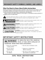
What You Need to Know About Safety instructions
Warning and important Safety instructions appearing in this manual are not meant to cover
all possible conditions and situations that may occur. Common sense, caution, and care
must be exercised when operating or cleaning tools and equipment.
Always contact your dealer, distributor, service agent, or manufacturer about problems or
conditions you do not understand.
This is the safety alert symbol. It is used to alert you to potential personal injury hazards.
y all safety messages that follow this symbol to avoid possible injury or death.
_
ANGERwill
indicates
imminently
hazardous
avoided,
result an
in death
or serious
injury. situation which, if not
_
ARNING
indicates
hazardous
situation which, if not
avoided,
could
result ainpotentially
death or serious
injury.
_
AUTIONmay
indicated
a potentially
hazardous
situation which, if not
avoided,
result in
minor or moderate
injury.
_
potentially used
hazardous
which,
not avoided,
mayaresult in
CAUTION
withoutsituation
the safety
alertif symbol
indicated
property damage.
IMP RTANTSAFETYINSTRUCTIONS
To
reduce the risk of fire, electrical
shock, or injury when using your air
conditioner, follow these basic precautions:
= Plug into a grounded
3-prong outlet.
Do not use an extension
• DO not
remove
ground
prong.
Unplug air conditioning
before servicing.
• Do not use
an adapter.
cord.
Use two or more people to move
and install air conditioner.
SAVE THESE INSTRUCTIONS
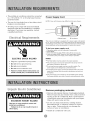
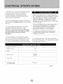
• The portable air conditioner should be connected
to a 115 V, 60 Hz, 15- or 20-amp fused 3-prong
grounded outlet.
The use of a time-delay fuse or time-delay
breaker is recommended.
circuit
Power Supply
NOTE:
Your
unit's
Cord
device
may differ
from
the one shown.
B
All wiring must comply with local and national
electrical codes and be installed by a qualified
electrician. If you have any questions, contact
a qualified electrician.
Ebctdcal
/equirements
A Reset Button
B Test Button
This room air conditioner is equipped with a power supply cord required
by UL. This power supply cord contains state-of-the-art
electronics that
sense leakage current. If the cord is crushed, the electronics detect leakage
current and power will be disconnected
in a fraction of a second.
To test your power supply cord:
1. Plug power supply cord into a grounded
2. Press RESET.
3-prong
outlet,
3. Press TEST (listen for click; Reset button will trip and pop out).
4. Press and release RESET (listen for click; Reset button will latch
and remain in).The power supply cord is ready for operation,
ELECTRIC SHOCK HAZARD
Plug into a grounded 3-prong outlet.
Do not remove ground prong.
Do not use an adapter.
Do not use an extension cord.
• Failure to follow these instructions can
result in death, fire, or electrical shock.
NOTES:
• The Reset button must be pushed in for proper operation.
• The power supply cord must be replaced if it fails to trip when the
test button is pressed or fails to rest,
• Do not use the power supply cord as as an off/on switch, The
power supply cord is designed as a protective device.
• A damaged power supply cord must be replaced with a new power
supply cord obtained from the product manufacturer and must not
be repaired,
• The power supply cord contains
the tamper-resistant
Unpack the Air Conditioner
Remove
no use serviceable
par_s. Opening
case voids all warranty and performance
packaging
claims,
materials
Remove and properly dispose of packaging materials.
Remove tape and glue residue from surfaces before
turning on the air conditioner. Rub a small amount
of liquid dish soap over the adhesive with your fingers.
Wipe with warm water and dry.
Do not use sharp instruments, rubbing alcohol,
flammable fluids, or abrasive cleaners to remove
tape or glue. These products can damage the
surface of your air conditioner.
Handle air conditioner
with care.
Thank you for choosing this room air conditioner to cool your home. This USE AND CARE MANUAL
provides information necessary for the proper care and maintenance of your new room air conditioner.
If properly
maintained,
your air conditioner
instaflation
difficulties,
read instructions
instaflation
and operation
will give you many years of trouble free operation.
completely
before starting.
This manual contains
To avoid
information
for the
of your room air conditioner.
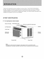
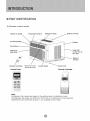
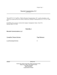
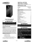
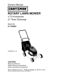
,-PART IDENTIFICATION
For mechanical
Interior Air Outlet
control
Horizontal
model
Air Vane
_'
Fresh Air Lever(for
'\ Vertical Air Vane
8K model only)
Cabinet
Air Filter(Inside)
Front
Panel
Interior Air
Inlet Grille
Exterior
Air Inlet
Control
.J
Knob
J
J
........Power Cord
Note:
The figures in this manual are based on the external view of a standard model.
Consequently,
the shape may differ from that of the air conditioner
you have selected,
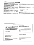
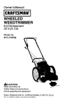
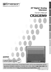
PART MDENTMFMCATMON
D,- Remote
contro_
Interior Air Outlet
modem
Horizontal Air Vane
Exterior Air Inlet
Vertical Air Vane
Air Filter
Cabinet
Front Panel
Rear Grill
(in the rear of
the unit)
Interior Air
Inlet Grille
Exterior
Air Inlet
Remote Controller
Control
Panel
Fresh Air Lever
(Model 8K Only)
Control Panel
Power Cord
Remote Controller
Airconditione_
Note:
The figures in this manual are based on the external view of a standard model.
Consequently, the shape may differ from that of the air conditioner you have selected.
Horizontal air vane and Fresh air lever is not available for this model
1. All wiring must comply with local and national
electrical codes and must be installed by a
licensed electrician.
Once you have any
questions regarding the following
contact a licensed electrician.
2. Check available
wiring problems
this unit.
If the air conditioner
has a serial plate rating
of 1 15 volts and up to and including 7.5 amps
the unit maybe on a fuse or circuit breaker
with other devices.
However, the maximum
amps of all devices on that fuse or circuit
breaker can not exceed the amps of the fuse
of circuit breaker.
instructions,
power supply and resolve any
BEFORE
installing and operating
3. For your safety and protection,
If the air conditioner
has a serial plate rating
of 1 15 volts and greater than 7.5 amps it
must have its own fuse or circuit breaker,
and no other device or unit should be
operated on the fuse or circuit breaker.
this unit is
grounded through the power cord when
plugged into a matching wall outlet. If you are
not sure whether
your wall outlet is properly
grounded,
please
electric Jan.
consult
4. The wall outlet(3-pin)
(3-pin) on the power
CAPACITY
RATED VOLTS
AMPS
of personal
injury,
to the unit before
must match the plug
cord supplied
with the unit.
DO NOT use plug adapters or extension cords.
See (Table f) for receptacle and fuse information.
COOLING
To avoid the possibility
disconnect
the power
installing or servicing.
a licensed
5. The rating plate on the unit contains
and other technical
data.
electrical
The rating plate is located
on the right side of the unit.
5K.
6K,
8K
125
15
WALL OUTLET
FUSE SIZE
Time Delay Fuse
(or circuit breaker)
15
Plug type
Table 1
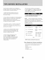
Your RoomAir
Conditioner
unit is designed to
be highly efficient and save energy. Follow these
recommendations
for greater efficiency.
Your RoomAir Conditioner
was designed
for easy installation in a single or double-hung
window. NOTE: This unit is NOT designed for
vertical (slider type) windows.
1. Select thermostat setting that suits your
comfort needs and leave the thermostat at
that chosen setting.
To avoid installation/operating
difficulties,
read the instructions thoroughly.
2. The air filter is very efficient in removing
airborne
particles. Keep the air filter clean. Typically, filter
should be cleaned once a month. More
frequent cleaning may be necessary
on outdoor and indoor air quality.
depending
NOTE:
Save the shipping carton and packing
materials for future storage or transport of the unit.
Please check the contents of the hardware kit
against the corresponding
installation of the unit.
3. Use drapes, curtains, or shades to keep direct
sunlight from heating your room, but DO NOT
obstruct the air conditioner. Allow three (3) inches
around unit to circulate.
See lists below. (Fig. 1)
3/4"Screws
(12)
4. Start your air conditioner before outdoor
air becomes hot and uncomfortable. This
(_
1/4" Screws
avoids an initial period of discomfort
(_
Top Channel(I)
factory installed
while
model check list, prior to
(_
(8)
(_
the unit is cooling off the room.
Foam(1 )
Side Curtain RH(1)
Side Curtain LH(1)
L Bracket(2)
5. When outdoor temperature
Seal(l)
is cool
Side Bracket(2)
enough, use HIGH or LOW FAN
only. This circulates indoor air, providing
some cooling comfort, and utilizes less
electricity than when operating on a
cooling setting.
Fig.1
NOTE: Surplus
Tools Needed
screw(s)
for spare use.
for Window
Installation:
• Screw Drivers: Both Phillips and Flat Head
• Power Drill: 1/8 inch diameter drill bit
• Pencil
• Measuring
• Scissors
• Carpenter's
Tape
Level
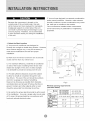
F.Yourunitwasdesigned
toevaporate
condensation
undernormal
conditions.
However,
underextreme
Because
thecompressor
is located
onthe
humidity
conditions,
excesscondensation
maycause
controls
sideoftheunit(rightside),thisside
the basepantooverflow
totheoutside.
willbeheavier
andmoreawkward
tomanipulate. Theunitshouldbeinstalled
wherecondensation
Inadequate
support
oncontrolsideoftheunit
run-offcannotdriponpedestrians
orneighboring
canresultinpersonal
injuryanddamage
toyour
properties.
unitandproperty.
Therefore,
itis recommended
tohavesomeone
assistyouduringtheinstallation
ofthisunit.
1.SelecttheBestLocation
A.Yourroomairconditioner
wasdesigned
to
fiteasilyintoa singleordoublehungwindow.However,
sincewindow
designs
vary,itmaybenecessary
to
makesomemodifications
forsafeandproper
installation.
<
/
Awning
B.Makesurethewindow
andframearestructurally
soundandfreefromdry,rottedwood.
C.Formaximum
efficiency,
installtheairconditioner
onsideofthehouseor building
whichfavorsmore
shadethansunlight.
If theunitisindirectsunlight,
it isadvisable
toprovide
anawning
overtheunit.
"_-----X
30" Min.
Side
D.Provide
sufficient
clearance
aroundthecabinet
toallowforampleaircirculation
through
theunit.
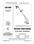
See(Fig.2). The rear of the unit should be outdoors
obstruction
E. Be certain the proper electrical outlet is within reach
of the installation. Use only a single outlet circuit rated
at 15 amps. All wiring should be in accordance with
local and national electrical codes.
obstacle.i
Ground
and not in a garage nor inside of a building.
Keep unit as far away as possible from obstacles
and obstructions and at least 30" above the floor or
ground. Curtains and other objects within a room
should be prevented from blocking the air flow.
_
Fence,
wall, or
other
Fig.2
Window opening requirements
(see table below)
""---._od
Size
el
_
Cabinet size
(W*H*D)
Min, Window
Width
AW-05CM1FD
AW -05OR1FM
AW-06CRIFM
AW -06CM1 FD
17.7" "12,4" "15.7"
AW -08CR1 FM
AW-08CM1FD
18.5" "13.7" "17.7"
20.9"
21.6"
Max.
Width Window
31.9"
32.6"
Min, Window
Height
3 8"
1 .
1 5.4"
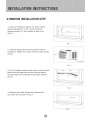
WINDOW INSTALLATION
STEP
1. If your air conditioner cabinet 18" wide, it will fit
window openings 21" to 32" in wide. Minimum
opening height is 14" from bottom of sash to sill
(Fig. 1).
Fig. 1
2. Insert the guide panels into the guides of the air
conditioner. Fasten the curtains to the unit with screws
(Fig. 2).
1/4"
Fig. 2
3. Cut the adhesive-backed
seal strip the window width.
Remove the backing from the seal strip and attach
the seal strip to the underside of the bottom window.
(Fig. 3)
Fig. 3
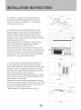
4. Measure the inside window sill width and find
the center line as shown in Fig. 4.
Fig. 4
Screws
5. Install the L brackets on the outer sill with the
Outer
Inner
Sill
Sill
Center
Line
short side of the bracket against the back of the
inner sill. Install one L bracket 7.5" to each side
of center line. See Fig. 5.
Short
6. Carefully lift the air conditioner and slide it into
the open window. Make sure the bottom guide of
the air conditioner drops into the notches of the L
Side
Fig. 5
brackets. When the air conditioner drops into the L
brackets, the air conditioner will be centered in window
opening as show in Fig. 6.
While steadying the air conditioner, carefully bring
the window sash down behind the top channel
of the air conditioner, as shown in Fig. 7.
First, fix both sides onto the window sill with two 3/4"
screws and one 2/5" screw ( which is unscrewed from
each side of the unit). Then fix top channel to widow
sash with one 3/4" screw and fix side curtain frames
with four 3/4" screws as shown in Fig.6.
Fig.
7. If storm window presents interference, fasten a
2" wide wood strip to the inner window sill across
the full width of the sill. The wood strip should be thick
6
_jSeal
enough to raise the height of the window sill so that
the unit can be installed without interference from the
storm window frame, as show in Fig. 8.
Top of wood strip should be approximately 3/4" higher
than the storm window frame to help condensation to
drain properly to the outside.
Install a second wood strip (approximately 6" long by
L Brack_tt---_
11/2"wide and same thickness as first strip) in the center
of the outer sill flush against the back of the inner sill.
Screw the L brackets into this strip.
Fig.7
3/4"Clearance
This will raise the L bracket as shown in Fig. 8.
_Stolrn
window
inne_rr siJI
r_]
Fig.8
fr .....
_Mechanicai
control
model
MODE
The mode knob controls fan speeds and cooling
speeds. To set desired cooling temperature,
rotate the mode knob dial to the appropriate
simply
OFF
setting. See Fig. 9.
Thermostat
THERMOSTAT
knol_
Mode knob
The thermostat automatically controls the cooling
cycle (compressor) of the air conditioner to maintain
room temperature. However, the fan motor will
continue to operate after the compressor
cycle) is completed.
(cooling
See Fig.9.
Fig.9
LOW FAN will circulate the air at a minimum speed
without cooling.
HIGH FAN will circulate the air at a maximum
without cooling.
speed
LOW COOL provides cooling, automatically with
minimum air circulation. Recommended for nighttime use.
When using FAN control,
turn slowly allowing
When using THERMOSTAT,
HIGH COOL provides cooling, automatically with
quick cooling or for extremely hot days. Once room
is cooled, reduce setting to LOW COOL.
OFF will completely
shut-off the unit.
NOTE: After setting the mode, allow 3
minutes before switching to another mode.
unit
to adjust.
minutes
before
changing
be sure to allow three
temperature.
too quickly may cause an overload
blown fuse.
Adjusting
resulting
in a
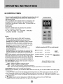
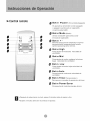
>- CONTROLPANEL
You can easily operate this air conditioner by pressing relevant
button on the control panel as well as the remote control,
ON/OFF BUTTON
Control Panel
The air conditioner will be started when it is energized or will
be stopped when it is in operation, if you press this button.
When the air conditioner is heating, allow 3 minutes after you
press this button.
Mode button
Each time Mode button is pressed, the operation
mode is changed in sequence:
5K_ 6K. 8K cooling only:
COOLING
FAN ONLY
ENERGY SAVING
COOLING
Mode:
Cooling (with fan speed Lo, Med. High): Compressor
cyctes to maintain Temperature Set Point, Fan remains
on at selected speed during compressor OFF cycle.
Cooling (Auto Fan Speed): Compressor Cycles to maintain
Temperature Set Point. Fan speed is controlled from room
temperature. Fan remains on during compressor OFF cycle.
Fan Only: Circulates
and riflers room air at selected speed.
Energy Saving (with fan speed Lo. Med. High)=
Fan cycles ON and OFF with compressor over a wider
range of temperatures,
Indication
Energy Saving (with Auto Fan Speed): Fan cycles ON and
OFF with compressor at a wider range of temperatures. Fan
speed dur¿ng ON cycle is dependent
NOTE= After
switching
setting
the mode.
to another
Temperature
display
mode.
range
allow three (3} minutes
below
Room Temperature
above 99°F, the Temperature
Sutton:
auto. low. medium,
High
Medium
Low
Auto
Timer
Highest
Normal
Lowest
Works
Button:
before
32°E the Temperature
Used to select
fan speed
Medium fan speed
Room
is from 0°C (32°}=) to 38_C (99°FL
Room Temperature
Fan Speed
Auto fan speed
,J_ Lowfan spee_
on room temperature.
In the FAN ONLY Mode.
symbols of LED on control panel :
display
L0.
display
H1.
_" High fan speed
in sequence
_
C0oltng
,,_ Fan only
88-
u,_
_
Energy-saving Display set ternp
Display set trainer
Q Timer
Above LED _ights on when
the relevant mode is in use.
and high.
fan speed for maximum cooling
fan speed for average cooling
and quietest s_eed, greater dehumidification
ie Cooling and Energy-Saving mode to vary fan speed based on room temperature.
Used to set or cancel
When the unit is in operation,
is 0 to 24 hours.
timer
operation.
you can set OFF TIMER. When the unit is OFF, you can set ON TIMER. T_mer setting
if the OFF TIMER is set. the time LED displays
the remaining
range
time to turn off the unit for only 12 seconds, then LED
shifts to display set temperature,
ff you press TIMER button within the 12 seconds, OFF TIMER will be cancelled,
if the ON TIMER is set. the timer LED displays the remaining time to turn on the unit. If you want to cancel ON TIMER.
press TIMER button.
A V
Button:
Used to set room temperature
NOTE: Temperature
setting
in COOLING
mode or used to set time in TIMER mode.
range is from 19_C (66_F) to 31 °C (88°F).
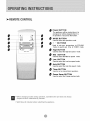
: REMOTE CONTROL
Power BUTTON
The appliance will be started when it is
energized or will be stopped when it is
in operation, if you press this button.
Power
Timer
MODE BUTTON
Used to select the operation mode.
Mode
Powe'TSave r
_iiiiiiiiiiii_iiiiiiii
+ -- BUTTONS
Used to set room temperature in COOLING
mode or used to set time in TI MER mode.
High BUTTON
Used to select the high fan speed mode.
Mid BUTTON
Used to select the Mid fan speed mode.
Low BUTTON
Used to select the Low fan speed mode.
Auto BUTTON
Used to select the Auto fan speed mode.
Timer BUTTON
Used to set or cancel timer operation..
Power Saver BUTTON
Used to select the Energy-saving mode,
at once. modes
Wait three
minutes.
o respond
hen changing
during(3)operation,
• Wait three (3) minutes before restarting
sometimes
the appliance.
the unit does not always
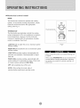
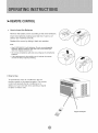
: REMOTE CONTROL
How to insert the Batteries
Remove the battery cover according
to the arrow direction.
Insert new batteries making sure that the (+) and (-) of
battery are matched correctly.
Reattach the cover by sliding it back into position.
Note:
,
Use 2 LR06 AAA (1.5 volt) batteries.
Do not use rechargeable
batteries.
Replace batteries
with new ones of the same type
when the display
becomes
dim.
* Do not mix old batteries
properly.
with
new ones.
Dispose
* If the replacement
is done within one (1) minute,
control
will keep original
presetting.
• How
of old batteries
the remote
to Use
To operate the room air conditioner, aim the
remote control to the signal receptor. The remote
control will operate the air conditioner at a
distance of up to 23 feet when pointing at signal
receptor of indoor unit.
\
Signal receptor
Whenservicing
theairconditioner,
besureto
turnthemodeswitchtothe"OFF"position
and
disconnect
thepowercordfromtheelectrical
outlet.
[e,Z_eJul[e]_J
DO NOT forget to install the air filter. If the air
conditioner is left to operate without the air filter,
dust is not removed from the room and may
cause your air conditioner to fail.
When the air filter inlet grill and cabinet are dirty,
wipe with lukewarm water (below 104°F).Use of
mild detergent is recommended.
1. DO NOT use gasoline, benzine, thinner or
other chemicals on the air conditioner as these
substances may cause damage to the paint finish
and deformation of plastic parts.
2. Never attempt to pour water directly in front
of the unit as this will cause deterioration of
the electrical
Cleaning
insulation.
Cleaning
of Air Filter
1. Remove dust clogged in the filter by
tapping it or vacuum clean it.
2. Wash the filter well with lukewarm
the Air Filter
40°C (104°F)while
water below
rubbing lightly. To get better
If the air filter becomes clogged with dust, air-flow
is obstructed and reduces efficiency. The air filter
results, wash it with soapy water or a neutral
cleaning agent.
should be cleaned once a month. More frequent
3. Rinse the filter well using clean water then
cleaning may be necessary
and indoor air quality.
dry completely.
depending
on outdoor
End-of-Season
Air Filter
Removal
Care
1. Operate the fan alone for half a day to dry out
the inside of the unit.
The air filter on the above models is located
behind the air intake front grill.
2. Turn off power and remove plug from wall socket.
3. Clean filter.
To remove the air filter, grasp the filter handle(tab)
located on the up (center) side of the air inlet grille
and slide the air filter to the up.
To reinstall the air filter, reverse the above
procedure.
4. Store in a dry location.
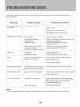
Frequently,
a problem
possible solution.
is minor
call may not be necessary,
POSSIBLE
PROBLEM
Air conditioner
and a service
will
use this troubleshooting
CAUSE
SUGGESTED
No power to the unit.
Check connection
power source.
not operate
guide
for a
SOLUTION
of power cord to
Check fuse or circuit breaker.
Set MODE knob to position other
than "OFF".
Inefficient
or no cooling
Dirty air filter.
Clean or replace
Inappropriate capacity
for application.
Check with dealer to determine
capacity for application.
air filter.
Blocked air flow.
Remove obstruction
outdoor louvers.
Power interruption, settings
change too quickly, or
compressor overload tripped.
Let fan run to restart compressor
(in approximately
10 minutes).
Noisy unit
Loose parts.
Inadequate support.
Tighten loose parts.
Provide additional support to unit.
Odors
Formation of mold, mildew, or
algae on wet surfaces.
Remove drain plug and drain base pan.
Replace drain plug.
proper unit
from grill or
Clean unit thoroughly.
Water dripping outside
Condensation run-off is normal
during hot and humid weather
Add flexible
Water dripping
Unit is not properly angled to
allow water to drain outside,
Unit must be installed on an angle for proper
condensation run-off. Check the unit and
make adjustments.
Low outside temperature.
When outdoor
65°F or below,
cooling mode.
operation until
Unit air filter is dirty.
Remove
inside
Ice or frost build-up
tubing to redirect water flow.
temperature is approximately
frost may form when unit is in
Switch unit to FAN (only)
frost melts.
and clean filter.
NOTE:
If circuit
breaker
is tripped
repeatedly,
or fuse is blown
more
than once,
contact
a ficensed
technician.
II REMOTECONTROLAW-05CR1FM m AW-08CR1FM
5 YEAR
FULL
WARRANTY
This product is warranted for five years from the date of original purchase. Any part which fails in materials
or workmanship will be replaced within the warranty period. This warranty covers in-home service.
A copy of your proof-of-purchase,
with date of purchase, and product name included, is required to
arrange this service repair.
For the name and location of an authorized service provider nearest you, please CALL 1-877-465-3566.
Please reference product name, brand name, and model number when you call.
This warranty does not apply if the damage occurs because of accident, improper handling or operation,
shipping damage, abuse, misuse, unauthorized repairs made or attempted, or the use of the product
for commercial use, or any other use for which it was not intended.
ALL WARRANTIES, EXPRESSED OR IMPLIED, LAST FOR FIVE YEARS FROM THE DATE OF ORIGINAL
PURCHASE. THIS WARRANTY DOES NOT COVER LIABILITY FOR INCIDENTAL OR CONSEQUENTIAL
DAMAGES FOR ANY CAUSE WHATSOEVER.
This warranty is extended to the original owner and any succeeding owner for products purchased for home
use within the USA. Some states do not allow the exclusion or limitation of incidental or consequential
damages. This warranty gives you specific rights, and you may also have other rights which may vary
from state to state. To know what your legal rights are, consult your local or state consumer
affairs
office or your state's Attorney
General.
II MECHANICAL CONTROLAW=05CM1FD m AW=08CM1FD
1 YEAR
FULL
WARRANTY
4 YEAR
EXTENDED
PLUS
WARRANTY
ON THE SEALED
This product is fully warranted for a period of one year
of original purchase. Any part which fails in materials
warranty period. This warranty covers in-home service.
of purchase, and product name included, is required to
SYSTEM
plus four years on sealed system from date
or workmanship will be replaced within the
A copy of your proof-of-purchase,
with date
arrange this service repair.
For the name and location of an authorized service provider nearest you, please CALL 1-877-465-3566.
Please reference product name, brand name, and model number when you call.
This warranty does not apply if the damage occurs because of accident, improper handling or operation,
shipping damage, abuse, misuse, unauthorized repairs made or attempted, or the use of the product
for commercial use, or any other use for which it was not intended.
ALL WARRANTIES, EXPRESSED OR IMPLIED, LAST FOR FIVE YEARS FROM THE DATE OF ORIGINAL
PURCHASE. THIS WARRANTY DOES NOT COVER LIABILITY FOR INCIDENTAL OR CONSEQUENTIAL
DAMAGES FOR ANY CAUSE WHATSOEVER.
This warranty is extended to the original owner and any succeeding owner for products purchased for home
use within the USA. Some states do not allow the exclusion or limitation of incidental or consequential
damages. This warranty gives you specific rights, and you may also have other rights which may vary
from state to state. To know what your legal rights are, consult your local or state consumer affairs
office or your state's Attorney General.
Gracias per elegir este aire acondicionade
para enfriar su hegar. Este MANUAL DE USO Y MANTENIMIENTO
proporciona la informaciOn necesaria para cuidar y mantener en forma adecuada su nuevo aire acondicionado.
Funcionard sin problemas durante muchos aries si le brinda el mantenimiento apropiado. Para evitar
problemas al instalarlo, lea completamente las instrucciones antes de comenzar. Este manual contiene
informaciOn acerca de la instalaciOn y el funcionamiento
del aire acondicionado
para habitaciones.
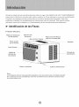
Identificaci6n de las Piezas
:_ Modelo
Mec&nico
Aleta de Aire
Horizontal
\
\, Aleta de Aire Vertical
Rejilla de Ventilaci6n
de Aire Interior
\\\\\\\\
Palanca de Aire Fresco
(s61o en el modelo 8K)
\
Filtro de Aire
(en el interior)
Gabinete
Panel Frontal
Rejilla
Entrada
Aire
Entrada de
Aire Exterior
de
de
interior
Tirador
Controlado
Cable de Alimentaci6n
Nota:
Las im6genes de este manual est(_n basadas en la vista externa de un modelo est_ndar.
En consecuencia,
es probable que la forma sea diferente a la delaire acondicionado
que usted seleccion6.
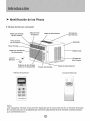
Identificaci6n de las Piezas
}b Modelo de Remoto controlador
Rejilla de Entrada
de Aire Interior
Aleta de Aire
Horizontal
Aleta de Aire Vertical
Entrada de
Aire Exterior
Filtro de Aire
(en el interior)
Gabinete
Panel Frontal
Rejilla de Ventilaci6n
de Aire Interior
Control
Remoto
Reji!!a Atras
Entrada de
Aire Exterior
....
Palanca de Aire Fresco
(s61o en el modelo 8K)
Panel de Control
Tirador Controtado
Cable de Aiimentaci6n
Control
Remoto
L?? X i7
¸
l
®r:
Nota:
Las in-_.igenes de este manual estdn basadas en la vista externa de un modelo est_tndar.
En consecuencia,
es probable que la forma sea diferente
a la del aire acondicionado
que usted seleccion6.
1. Todos los cables deben cumplir
el6ctricos
locales y nacionales
un electricista
licenciado.
relacionadas
comuniquese
con los c6digos
y los debe instalar
Si tiene preguntas
con las siguientes instrucciones,
con un electricista
licenciado.
2. Verifique el suministro de energ[a disponible y
resuelva cualquier problema con los cables ANTES
de instalar y hacer funcionar
esta unidad.
3. Para su seguridad y protecci6n, esta unidad estd
conectada a tierra a traves del cable de alimentaci6n
cuando se Io enchufa a un tomacorriente
provisto de conexi6n
que el tomacorriente
Para evitar lesiones fi sicas, desconecte
suministro
de energia
de la unidad
antes de instalarla o repararla.
a tierra. Si no est6 seguro de
de pared cuenta con la
conexi6n a tierra apropiada,
electricista licenciado.
4. El tomacorriente
de pared
consulte
Consulte
de pared (de 3 clavijas)
de enchufe
debe
ni cables de extensi6n.
la Tabla 1 para obtener informaci6n
de recept6culos
Tipos
de Recept6culos
5K, 6K, 8K
Capacidad
y Fusibles
de Voltios
125
acerca
Amperios
y fusibles.
5. El r6tulo de la unidad contiene datos electricos
t6cnicos. Dicho r6tulo se encuentra en el lado
derecho
el
con un
coincidir con el enchufe (de 3 clavijas) del cable de
alimentaci6n suministrado con la unidad. NO utilice
adaptadores
Si el r6tulo del aire acondicionado
indica 1 15
voltios y hasta 7.5 amperios,
la unidad se
puede conectar
a un cortacircuito
o fusible
utilizado por otros dispositivos.
No obstante,
la suma de los amperios
m6ximos de todos
los dispositivos
conectados
a dicho
cortacircuito
o fusible no deben exceder los
amperios
del mismo.
Si el r6tulo del aire acondicionado
indica 115
voltios y m6s de 7.5 amperios, debe tener su
propio fusible o cortacircuito y no se deber6
conectar ningan otro dispositivo o unidad a dicho
fusible o cortacircuito.
y
15
Tomacorriente
de Pared
de la unidad.
Tama_o
del Fusible
15
Fusible con Retardo
Tipo de enchufe
(o Cortacircuito)
Tabla
1
Su unidad de AireAcondicionado
para Habitaciones
se ha disen_ado para Iograr un alto rendimiento y
ahorrar energia electrica. Siga las siguientes
sugerencias para Iograr un mayor rendimiento.
El AireAcondicionado
dise_ado
en ventanas
unidad
para Habitaciones
de modo tal que resulte
armadas
sencillas
NO se ha disehado
se ha
Ricil su instalaci6n
o dobles.
NOTA:
para ventanas
esta
verticales
(de tipo deslizante).
1. Ajuste
el termostato
agradable
y d6jelo
a un nivel que le resulte
en el nivel seleccionado.
las instrucciones.
2. El filtro de aire es muy eficiente
particulas
que se desplazan
limpio el filtro de aire.
limpiarse
a la hora de eliminar
por el aire. Mantenga
Pot Io general,
el filtro deber6
una vez al mes. Es probable
necesario
limpiarlo
de la calidad
que sea
con m6s frecuencia
del aire exterior
dependiendo
o interior.
NOTA:
conserve
la caja de la unidad
de empaque
para almacenarla
futuro.
de instalar
Antes
contenido
del juego
del modelo
listas
(Fig.
y los materiales
o transportarla
la unidad
de herrajes
correspondiente.
compare
en el
el
con la lista de control
Consulte
las siguientes
1 ).
3. Puede utilizar tapices, cortinas o pantallas para
evitar que la luz directa del sol caliente su habitaci6n,
pero NO obstruya el aire acondicionado. Permita
que el aire circule alrededor de la unidad sin
obstrucciones.
(_>
Tornillos de 3/4" (12)
Tornillos
4. Encienda
el aire acondicionado
temperatura
exterior
sea demasiado
antes
de que la
elevada
desagradable.
De esta manera evitar6
mientras la unidad enfria la habitaci6n.
_
de 1/4" (8)
Sello (1)
Espuma (1)
Canal Superior (1)
y
instalado en la fdbrica Cortina Lateral Derecha (1)
sufrir calor
5. Cuando la temperatura exterior es Io suficientemente
fresca, utilice s61o HIGH FAN (ventilador al m_ximo) o
LOW FAN (ventilador al mf nimo). Esto hace que el aire
interior circule a una temperatura agradable y consume
menos energia electrica que si hiciera funcionar la
unidad como enfriador de aire.
Soporte en L (2)
Cortina Lateral Izquierda (1
Soporte Lateral (2)
_
l_
Fig.1
Nota:
Torni!lo
Excedente
Para d Uso de Reserva.
Herramientas Necesarias para la Instalaci6n en Ventana:
Destornilladores:
Philips y de cabeza plana
Taladro el_ctrico: broca de 1/8 pulgada de di6metro
L_piz
Cinta matrica
Tijeras
Nivel de carpintero
V_
I_ _ _Z_II_
_ _IIV_l
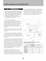
F. La unidad estd dise_ada
bajo condiciones
Debido
a que el compresor
de los controles
se encuentra
(a la derecha
bajo condiciones
de extrema humedad, es probable que la condensaci6n
del lado
de la unidad),
para evaporar la condensaci6n
normales. No obstante,
excesiva haga que la bandeja base se desborde hacia el
este
lado sen1 m_s pesado y mcis dificil de manipular.
Si la unidad no se sostiene bien de dicho lado
exterior. Por Io tanto la unidad deber6 instalarse
donde la descarga
de la condensaci6n
pueden
paso de peatones
ni en las propiedades
producirse
unidad
lesiones
y a su propiedad.
recomendamos
solicite
a otras
la Mejor
que facilita
armadas
sencillas
que los diseRos
probable
vecinas.
le
esta unidad
Ubicaci6n
para habitaciones
su colocaci6n
o dobles.
tiene un
realizar
/
debido
son tan variados,
que sea necesario
Toldo
en ventanas
No obstante,
de ventana
modificaciones
a la
personas.
A. El aire acondicionado
dise_o
y da_os
Pot Io tanto,
que para instalar
ayuda
I. Seleccione
ffsicas
en un lugar
no gotee sobre el
a
es
algunas
para Iograr una instalaci6n
segura
y
adecuada.
B. AsegLirese de que la ventana y el marco tengan
una estructura firme y que la madera no est6 rajada
ni podrida.
C. Para Iograr el m6ximo rendimiento, instale el aire
acondicionado del lado de la casa o edificio donde
Cerca,
30" Min.
Obstrucci6n
haya mds sombra que sol. Si la unidad se encontrara
expuesta a la luz del sol, es aconsejable colocarle un
toldo encima.
lateral
_
pared u
otro
obst(iculo.i
Suelo
D. Deje suficiente
espacio
alrededor
circulaci6n
del gabinete
permitir
una amplia
unidad.
Vea (Fig. 2). La parte
deber_
dar al aire libre y no a un garaje
un edificio.
Mantenga
obst6culos
que puedan
menos
precauciones
cualquier
otro objeto
obstruyan
ni al interior
de
Io m6s lejos posible
de
obstrucciones
para evitar
dentro
Fig.2
de la unidad
a 30" del nivel del piso o del suelo.
tomarse
que las cortinas
la unidad
tomacorriente
el_ctrico
tomacorriente
de 15 amperios
adecuado.
para el aire acondicionado.
con los c6digos
de un
Utilice
un
electricos
exclusivo
los cables
locales
Tama_o
_
Taman'0
delgabinete
(A*H*L)
cerca
con circuito
Todos
delo
_-....Mo
o
de una habitaci6n
de instalar
Requisitos
para las aberturas
(consulte
la siguiente
tabla)
de ventanas
y pot Io
Deberdn
el flujo de aire.
E. Aseg_rese
cumplir
de aire a traves de la
posterior
la unidad
causar
para
deberdn
y nacionales.
AW-05CM1FD
AW-05CR1FM
AW-08CR1FM
AWAw
-06CRI_06CM1FMFD
AW -08CM1FD
17.7" "12.4" "15.7"
Aberturaminima
deVentana
2 0.9"
Aberturam_xima
deVentana
31.9
MinutaAltura
de Ventana
13.8"
18.5" "13.7" "17.7"
21.6"
"
3 2.6"
1 5.4"
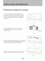
_Pasos para la instalaci6n en ventanas
1. Si el aire acondicionado tiene un gabinete de 18"
de ancho, podr6 colocarse en aberturas de ventanas
de 21"a 32" de ancho. La altura minima de abertura
es de 14" desde la parte inferior del marco hasta el
umbral (Fig. 1).
Fig. 1
2. Inserte los paneles guia en las gu[as del aire
acondicionado. Sujete las cortinas a la unidad con
los tornillos (Fig. 2).
_t"
Fig. 2
/l<
i
3. Corte la tira de sello adhesivo del ancho de la ventana.
Quite el revestimiento de la tira adhesiva y p6guela en el
interior de la parte inferior de la ventana (Fig. 3).
Fig. 3
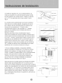
4. Mida el ancho del interior del umbral de la ventana y
deliria la I_nea central tal como se indica en la Fig. 4.
Fig. 4
Tornillos
de 1/4"
Jmbral
Extemo
Tornillo
de 3/4 " Umbral
la parte posterior del umbral interno. Instale un soporte
en L a 7.5" de cada lado de la Ifnea central. Vea la
Interne
Lf nea Central
5. Instale los soportes en L en el umbral externo, de
modo que la parte m_s corta del soporte apoye contra
Tornillo
Lado
det
de 3/4"
Corto
Soporte
./'"
Fig. 5.
6. Levante el aire acondicionado con mucho cuidado y
deslf celo por la ventana abierta. AsegQrese de que la
Fig.
5
Fig.
6
guia inferior del aire acondicionado se inserte en las
ranuras de los soportes en L. Cuando el aire
acondicionado apoye en los soportes en L, quedard
centrado en la abertura de la ventana tal como se
indica en la Fig.6.
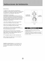
Mientras acomoda el aire acondicionado, baje el
marco de la ventana con mucho cuidado y ap6yelo en el
canal superior del aire acondicionado, tal como se indica
en la Fig. 7. Primero, ajuste ambos lados al umbral de la
ventana con dos tomillos de 3/4" y uno de 2/5" (que se
destornilla de cada lado de la unidad). Luego ajuste el
canal superior al marco de la ventana con un tornillo de
3/4" y ajuste los marcos de la cortina lateral con cuatro
tornillos de 3/4", tal como se indica en la Fig. 6.
7. Si una ventana resistente a huracanes interfiere,
adhiera una tabla de madera de 2" de ancho al umbral
Alrededor
de 5 °
interno de la ventana, a Io largo de todo el ancho del
umbral. La tabla de madera deber_ ser Io suficientemente
gruesa como para elevar la altura del umbral de la
ventana, de modo que la unidad pueda instalarse sin
que el marco de la ventana resistente a huracanes
interfiera, tal como se indica en la Fig. 8.
Para que sea atil, la parte superior de la tabla de madera
deber6 estar aproximadamente 3/4" m6s arriba que el
marco de la ventana resistente a huracanes para sumidero.
sopor
Fig.7
Instale una segunda tabla de madera (de aproximadamente
6" de largo por 1 1/2" de ancho y el mismo grosor de la
Espacio
primera tabla) en el centro del umbral externo contra la
parte posterior del umbral interno. Atornille los soportes
en L a esta tabla. Esto elevar_ el soporte en L tal como se
indica en la Fig. 8.
Fig.8
de 3/4"
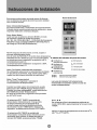
MODE (Modo)
La perilla de modo controla las velocidades de
ventilador y de enfriamiento. Para fijar una temperatura
de enfriamiento, simplemente haga rotar la perilla y
col6quela en el nivel deseado. Vea la Fig. 9.
THERMOSTAT (Termostato)
El termostato controla autom_ticamente
el ciclo de
OFF
Control de
Termostato \
Control
de Modo
enfriamiento (compresor) del aire acondicionado
para
mantener la temperatura del ambiente. No obstante, el
motor del ventilador continuar_ funcionando una vez
finalizado el funcionamiento
del compresor
enfriamiento).
Vea la Fig. 9.
(ciclo de
LOW FAN (Ventilador al Minimo) har_ que el aire
circule a una velocidad m _nima sin enfriar.
Fig.9
HiGH FAN (Ventilador al M('_ximo) har(i que el aire
circule a una velocidad m(:_xima sin enfriar.
LOW COOL (Fr_o Minimo) enfr_a el ambiente
autom6ticamente
con una circulaci6n m inima de aire.
Se recomienda durante la noche.
HIGH COOL (Frio M(iximo) enfria el ambiente
autom_ticamente
de manera r6pida o durante d ias de
calor intenso. Una vez que la habitaci6n est6 fr ia,
reduzca el nivel a LOW COOL.
OFF (Apagado)
apaga la unidad completamente.
NOTA: Despu6s de seleccionar
minutos antes de pasar a otro.
VentilaciOn de aire fresco
un nivel, espere 3
se ra a mantener
en la
posici6n cerrado. Usando s61o para limpiar humos
y/o odores de la habitaci6n, tire a comenzar. Vea
la Fig. 10.
Cuando utilice la perilla de control de ventilador,
hdgala girar lentamente
para permitir que la unidad
se adapte al nivel.
Cuando utilice THERMOSTAT,
aseg_rese de esperar tres
minutos antes de cambiar la temperatura.
Si la cambia
demasiado
r_pido es posible que cause una sobrecarga
y
se queme el fusible.
Panel de Control
Este aire acondicionado
se puede operar f6cilmente
con los botones
del panel de control
as_como
tambi_n
con el control
remoto.
Bot6n (Encendido/Apagado)
si presiona este bot6m encender_el aireacondicionado.
Cuando el aire acondieionado
esta de calefacci6n, se per
imprentar este bot6n 3 minutos despues,
Bot6n Mode (Modo)
Cada vez que se presiona el bot6n MODE. el modo
de operacian cambia en estas seeuencias:
5K, 6K, 8K COOLINGONLY.COOLING (Enfriamiento)
FAN ONLY ($61o ventilador)ENERGY
SAVING(Ahorro
de Energla) COOLING(Enfriamiento);
NOTA: Despu6s de seleccionar
un nivel, espere 3
minutos
antes de pasara
otro.
Con el modo de FAN ONLY, El recinto
de la temperatura
Dehabitaci6n ser_ Desde 0 _C(32°F) basra 38"C(99°F ).
La temperatura de la habitaci6n es superior a32 °F,
|a temperatura lucer_ LO.
La temperatura de la habitaci6n es superior a 99_F.
la temperatura lucer_ H1.
Bot6n Fan Speed (Velocidad del Ventilador)
Se utiliza para seleccionar la velocidad det ventilador
en secuencia: autom_tica, baja, media y alta (baja y
media son de]a misma velocidad de ventilador),
Bot6n Timer (Temporizador)
Se utiliza para programar o cancelar
funciona miento del temporizador,
el
S_mbolos del indicador
_
Ventilador en
velocidad automat{ca
Ventilador en
velocidad baja
Ventilador en
velocidad media
del panel dei control:
_:< Enfriamiertto
S_Io ventflador
O
Tem_orizador
_]: Aho_o
de energJa
Ventflador en
velocidad alta
Mostrar temperatura
f}jada
Mostrar hora programada
Las luces del indicador LED antedormente
mencionadas so encienden cuando se usan los
modos correspond_entes_
Cuando la unidad estaen funcionamiento,
puede
seleccionar
OFFTIMER
(Apagar Temporizador).
Cuando la unidad est_apagada, puede seleccionar
ON TIMER (Encender Temporizador),
El rango de horas para programarel temporizador
es de0 a24 horas.
Si selecciona OFF TIMER, la pantalla del
temporizador indicar_durante t2 se gundos
el tiempo restante para el apagado de la
unidad y luego indicar61a temperatura fijada.
Si presiona el bot6n TIMER dentro de esos 12
segundos, se desactivar_la funci6n OFF TIMER.
Si selecciona
ON TIMER,
la pantalla
det
temporizador indicar6el tiempo restante para el
encendido dela unidad_ Si desea cancelar la
funci6n (3 N TIMER, presioneel
bot6n TIMER.
Bot6n A T
Se utiliza para fijar la temperatura
modo COOLING e para programar
TIMER.
ambiente on
la hera en modo
NOTA: el range de temperaturasoscila
(66 °F)y 31°C (88°F).
entre t 9°C
: Control remoto
0
Bot6n
Power
(Encendido/Apagado)
El aparato se encenderd si est6 apagado
o apagar6 cuando este en operaci6n,
si oprime este bot6n.
0 Bot6n
Utilice
0
Mode
(Modo)
este bot6n para seleccionar
el modo de operaci6n.
Power
Timer
Mode
Power Saver
Temp/Time
0
Bot6n
0
Bot6n High
+-
Botones de ajuste de temperatura
oprima
para ajustarla
temepraturadel
cuarto.
oprima para programar la hora.
Paraajustarelmodoalta
ventilador.
Bot6n
velocidadde
Mid
Para ajustarel
modo mediana
baja) velocidad de ventilador.
Bot6n
Low
Para ajustarel
ventilador.
Bot6n
modo
baja velocidad
de
Auto
Para ajustarel
ventilador.
Bot6n
(almismo
modoauto
Timer
Para ponero
velocidad
de
(Temporizador)
cancelarla
operaci6n
de timer.
Bot6n Power Saver
Para ajustar
el modo de energia-ahorro.
, Despues de seleccionar un nivel, espere 3 minutos antes de pasar a otto.
• Espere 3 minutos antes de recomenzar el aparato.
Control
remoto
• Colocai6n
de las pilas
Retire la tapa de las en el sentido de la flecha.
Introduzca las pilas nuevas,con cuidado de
que coincidan los polos(+)y(-).
Vuelva a instalar la tapa,desliz_ndola otra vez
a su posici6n.
Nota:
• Utilice pilas 2 LR06 AAA (1.5V) .No uti_ce pilas
recargables.Sustituya
las pilas por otras nuevas del
mismo tipo cuando
la pantalla aparezca
atenuada,
• Si la sustituci6n
se realiza en el plazo de 1 minuto, el mando
a distancia
conservar_E
los valores prefijados
oridinales(Este
funci6n es s61o para controlador
remoto
de LCD).
• C c6mo
use
Para operar el aire acondicionado,
apunte el controlador
remoto la se_ar del receptor.
El controladorremoto
sera aoperar elaire acondiciondo
con unadiatancia
hasta23
piescuando
apuntaa
laseSar
del receptorde
la unidad.
Receptor
de seSal
Cuando
repare el aire acondicionado,
aseg_rese
de
colocar la perilla de modo en OFF y luego desconectar
el cable de alimentaci6n del tomacorriente
electrico.
1. NO utilice gasolina,
productos
qufmicos
estas sustancias
y deformar
bencina,
disolvente
u otros
en el aire acondicionado,
pueden dan_r el acabado
ya que
de pintura
las piezas de pkistico.
2. Nunca derrame agua directamente
en el frente de la
unidad ya que da_'ar[a
el_trico.
Limpieza
del Filtro
el aislamiento
de Aire
Si el filtro de aire se obstruye
queda obstruido
que sea necesario
dependiendo
con polvo, el flujo de aire
y reduce el rendimiento
filtro de aire deberci limpiarse
de la unidad.
se encuentra
limpiarlo con m6s frecuencia
de la calidad de aire exterior o interior.
mencionados
detr_s
de la rejilla de entrada
Para quitarlo
El
una vez al mes. Es probable
C6mo Quitar el Filtro de Aire
El filtro de aire de los modelos anteriormente
de aire delantera.
tome el mango del filtro (leng i.leta) ubicado en
la parte superior (centro) de la rejilla de entrada
deslfcelo hacia arriba. Para volver a
instalarlo
NO o[vide instalar el filtro de aire. Si el a[re
acondicionado
funciona sin el flltro de aire,
el poivo no se puede elim[nar de la
habitaci6n y es posible que la unidad se
descomponga.
Cuando la rejilla de entrada de aire y el
gabinete est6n sucios, I{ mpielos con agua
templada (por debaj de los 104 °F). Se
recomienda
el uso de un detergente
suave.
realice los procedimientos
anteriores
de aire y
a la inversa.
NO olvide instalar el filtro de aire. Si el aire acondicionado
funciona
sin el filtro de aire, el polvo no se puede eliminar
la habitaci6n
yes
L[mpieza del Filtro de A[re
1. Elimine el polvo acumulado en el fikro. Para
ello aplf quele unos golpes suaves o una
aspiradora dom6stica.
2. Lave bien el fikro con agua templada, de
temperatura inferior a los 40"C (104°F), mientras
Io frota suavemente. Para obtener mejores resukados,
I_velo con agua jabonosa o con un producto de
limpieza neutro.
3. Enjuague bien el filtro con agua limpia y luego
s6quelo completamente.
posible que la unidad se descomponga.
de
Cuidado de Fin de Temporada
1. Haga funcionar el ventilador durante medio dfa
para que se seque el interior de la unidad.
2. Ap_guelo y desench_felo del tomacorriente de
pared.
3. Limpie el fikro.
4. Almac6nelo en un lugar seco.
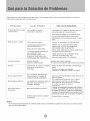
Generalmente
losproblemas
sonsencillosyes probable
quenoseanecesario
Ilamaraunt6cnico.
Estagufapuedeayudarlo
aresolverlos.
PROBLEMA
CAUSAPOSlBLE
SOLUCI6NSUGERIDA
Elaireacondicionado Launidadnorecibe
nofunciona
suministroelectrico.
Enfriapocoo nada
Unidadruidosa
Verifiquesi el cabledealimentaci6n
e
staconectado
altomacorriente.
Verifiqueel fusibleo el cortacircuito.
Fijeel FANCONTROL
(controldel
ventilador)en unaposiciOn
quenosea
OFF.
Filtrodeairesucio.
Limpieo reemplace
el filtro deaire.
Hableconel representante
para
Capacidadinadecuada
determinarcu(_l
es la capacidad
parala aplicaci6n.
adecuadaparala aplicacidn.
Flujodeaireobstruido.
Quitetodaobstrucci6n
dela rejllao de
Cortedeenergfaelectrica, laspersianasexteriores.
se cambidde
nivel
Hagafuncionarel ventiladorpara
demasiadorr_pido
o se
reiniciarel compresor(en
dispar6elinterruptorpor
10minutos).
sobrecargadelcompresor. aproximadamente
Olores
Piezassueltas.
Ajustelaspiezassueltas.
Soporteinadecuado.
Proporcionesoporteadicionala la unidad.
Formaci6n
demohouhongos Quiteeltapdndedrenajeylabandeja
sobrelas superficies
base.
hamedas.
Cambieel tap6ndedrenaje.
Limpiela unidadenformacompleta.
Goteaaguaafuera
Esnormalladescargade
condensaci6n
cuandoel
climaesG'flidoy h_medo.
Goteaaguaadentro
Launidadnoest6bieninclina
da comoparapermitirel
desagt_e
externo.
Seformahieloo
escarcha
Bajatemperaturaexterior.
Utilice
tuberfas
flujo de agua.
para
desviar
el
La unidad debe instalarse
con un ligero
desnivel
para permitir
una descarga
adecuada
de la condensaci6n.
Verifique
la unidad y realice los ajustes
necesarios.
Cuando la temperatura
exterior sea inferior a
los 65°F es posible que se forme escarcha
si
la unidad funciona en modo de enfriamiento.
Cambie el funcionamiento
de la unidad a FAN
(solamente)
Elfiltro deairedela unidad
est(_sucio.
flexibles
Quite
elfiltro
hasta
que la escarcha
se derrita.
ylimpielo.
NOTA:
Si el cortacircuito interrumpe la corriente varias veces o el fusible se quema mas de una vez, comuniquese
con un t_cnico licenciado.
II C0NTROLA REMOT0 AW-05CR1FM m AW-08CR1FM
GARANTJA
COMPLETA
DE 5 AltOS
Este producto se garantiza por 5 aSos a partir de la fecha de la compra orignaL Cualquier parte que falle
en materiales o la ejecuci6n ser& substituida dentro del periodo de la garanteia. Esta garantia incluye
servicio a domicilio. Una copia de su prueba de la compra, con la fecha de la compra del producto
incluida, se requiere para acordar esta reparaci6n del servicio.
Para el nombre y la Iocalizaci6n de un prestador de servicio autorizado Io m&s cerca posible a usted, Ilame
por favor al 1-877-465-3566. Refi6rase por favor al nombre del producto, a la marca, y al nQmero de
modelo cuando usted llama.
Esta garantia no se aplica se el danno ocurre debido a accidente, manejo u operaci6n incorrectos, daSos
de transporte, abuso, uso err6neo, reparacion no autorizada, el uso comercial del producto utro uso para
el cual no fuera pensado.
TODAS LAS GARANTJAS, EXPRESADAS O IMPLICADAS, DURAN POR 5 ANOS A PARTIR DE LA FECHA
DE LA COMPRA ORIGINAL. ESTA GARANTJA NO CUBRE LA RESPONSABILIDAD POR LOS DANOS
FORTUITOS O CONSECUENTES PARA CUALESQUIER CAUSA EN NINGUNCASO.
Esta garantia se extiende al dueSo original y a cualquier dueSo subsiquiente
para los productos comprados
para el uso casero dentro de los E.E.U.U_ Algunos estados no permiten la exclusi6n o la limitaci6n de daSos
fortuitos o consecuentes.
Esta garantia le da las derecho especfficos, y usted puede tambi6n tenet otras
erechos que puedan variar de estado a estado. Para saber cuAles son, sus derechas
su oficina local del consumidor
o a la procuraduria
de su estado.
legales consulte
a
II C0NTROLA MECANIC0 AW-05CM1FD m AW-08CM1FD
GARANTJA
COMPLETA
DE 1 ANOS
Este producto se garantiza por 1 aSos (5 aSos garantia para el compresor) a partir de la fecha de la
compra orignal. Cualquier parte que falle en materiales o la ejecuci6n ser& substituida dentro del
periodo de la garantia. La garantia includy servicio a domicilio. Una copia de su prueba de la compra,
con la fecha de la compra del producto incluida, se requiere para acordar esta reparaci6n del servicio.
Para el nombre y la Iocalizaci6n
de un prestador de servicio autorizado
Io m&s cerca posible
a usted, Ilame pot favor al 1-877-465-3566. Refi6rase por favor al nombre del producto, a la marca,
y al nQmero de modelo cuando usted llama.
Esta garantia no se aplica si el daSo ocurre debido a accidente, manejo u operaci6n incorrectos,
daSos de transporte, abuso, uso err6neo, reparacion no autorizada, el uso comercial del producto
utro uso para el cual no fuera pensado.
TODAS LAS GARANTJAS, EXPRESADAS O IMPLICADAS, DURAN POR 5 ANOS A PARTIR DE LA
FECHA DE LA COMPRA ORIGINAL. ESTA GARANTJA NO CUBRE LA RESPONSABILIDAD POR LOS
DANOS FORTUITOS O CONSECUENTES PARA CUALESQUIER CAUSA EN NINGUNCASO.
Esta garantia
se extiende
al dueSo original
y a cualquier
dueSo subsiquiente
para los productos
comprados
para el uso casero dentro de los E.E.U.U_ Algunos
estados
no permiten
la exclusi6n
o
la limitaci6n
de daSos fortuitos
o consecuentes.
Esta garantia le da las derecho especificos,
y usted
puede tambi6n
tenet
sus derechas
legales
otras erechos que puedan variar de estado
consulte
a su oficina local del consumidor
a estado. Para saber cu&les son,
o a la procuraduria
de su estado.
WIN'[
@2006 WlNT
. Kelon Air Conditioner Co., Ltd., and Kelon USA. Eric.At] rights reserved,
Kelon Air Conditioner Co., Ltd.
No.12 Qiaodong Road
Ronggui, Shunde, Guangdong China 528303
Pttnied
Kelon USA, inc.
8000 Virginia Manor Rd., Suite 170
Bettsville, MD 20705
i_ Ch_a
Version
No. 819042702-01