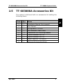
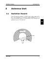
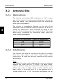
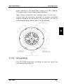
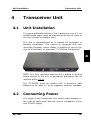
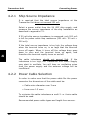
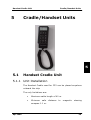
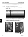
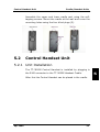
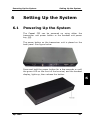
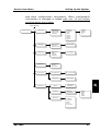
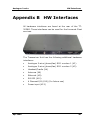
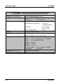
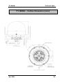
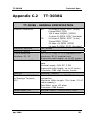
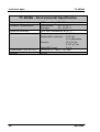
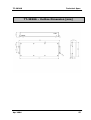
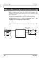
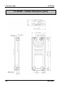
1
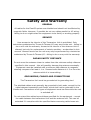
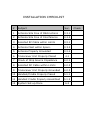
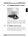
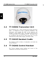
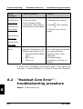
Thrane & Thrane A/S Capsat® Fleet33 TT-3088A Installation Manual Copyright© Thrane & Thrane A/S ALL RIGHTS RESERVED Information in this document is subject to change without notice and does not represent a commitment on the part of Thrane & Thrane A/S. It is recommended to download the latest version of the manual from the Thrane Extra net or request this from the distributor. © 2004 Thrane & Thrane A/S. All rights reserved. Printed in Denmark. Document No: TT98-120087-A Release date: 14 April 2004. Safety and Warranty GENERAL All cables for the Fleet33 system are shielded and should not be affected by magnetic fields. However, if possible do not run cables parallel to AC wiring – failing to do so might cause the equipment to be faulty or working properly. SERVICE User access to the interior of the Transceiver Unit is prohibited. Only technicians authorised by Thrane & Thrane A/S may service the unit - failing to do so will void the warranty. Access to the interior of the Antenna Unit is allowed, but only for replacement of certain modules - as described in this manual. General service on the unit may only be performed by a technician authorised by Thrane & Thrane A/S - failing to do so may void the warranty. RADAR SAFETY DISTANCE Do not move the antenna closer to radars than the minimum safety distance specified in this manual - this will possibly damage the antenna eventually. Equipment must be installed with a minimum safe distance to magnetic steering compass of at least 1.1 m. Personal safe distance is 1.3 m from the antenna while it is transmitting. GROUNDING, CABLES AND CONNECTIONS The Transceiver Unit must be grounded at its grounding stud. The shielded cables must generally be grounded in both ends, except for the cable between transceiver and Cradle, which shall not be grounded in the Cradle end. Connections of all types of equipment must be done while the unit is switched off. Do not extend the cables beyond those specified for the equipment – except the cable between the transceiver Unit and the antenna unit. This can be extended if it complies with the specified data concerning cable losses etc. POWER SUPPLY The operation voltage is 24 VDC. Note that long-term operation below 24 VDC should be avoided. It is recommended supply to provide supply from the ship hot 24 VDC power bus. Maximum peak power requirement for F33 is 110 W and maximum average power consumption is 60 W. If a 24 VDC power bus is not available, an external 115/230 VAC to 24 VDC power supply can be used. EQUIPMENT VENTILATION To ensure adequate cooling of the transceiver a 5 cm unobstructed space must be maintained around all sides of the unit (except the bottom side). Transceiver Unit ambient temperature range: -25 to +55°C. Failure to comply with the rules listed above will void the warranty! INSTALLATION CHECKLIST # Subject Sec. 1 Antenna Site Free of Obstructions 3.2.1 2 Antenna Site Free of Interference 3.2.2 3 Selected RF Cable within Limits 3.3.1 4 Antenna Mast within Specs. 3.3.2 5 Antenna Properly Grounded 3.3.4 6 Transceiver Unit Properly Placed 4.1 7 Check of Ship Source Impedance 4.2.1 8 Selected DC Cable within Limits 4.2.2 9 Transceiver Unit Properly Grounded 4.2.3 10 Handset/Cradle Properly Placed 5.1.1 11 Handset Cradle Properly Assembled 5.1.2 12 System Set-up Done 6.3 Check Blank page Table of Contents Table of Contents 1 About the Manual ...................................................... 1 2 TT-3088A System Units.............................................. 3 2.1 TT-3008G Antenna Unit ........................................ 3 2.2 TT-3038G Transceiver Unit.................................... 4 2.3 TT-3622E Handset Cradle ..................................... 4 2.4 TT-3620G Control Handset .................................... 4 2.5 TT-683088A Accessories Kit .................................. 5 3 Antenna Unit ............................................................ 7 3.1 Radiation Hazard ................................................. 7 3.2 Antenna Site ....................................................... 8 3.2.1 Obstructions .............................................. 8 3.2.2 Interference............................................... 8 3.3 Unit Installation................................................. 10 3.3.1 Antenna Coaxial Cable............................... 10 3.3.2 Antenna Unit Mast Design .......................... 11 3.3.3 Antenna Unit Mounting .............................. 12 3.3.4 Grounding ............................................... 13 4 Transceiver Unit...................................................... 4.1 Unit Installation................................................. 4.2 Connecting Power .............................................. 4.2.1 Ship Source Impedance............................. 4.2.2 Power Cable Selection ............................... 4.2.3 Grounding ............................................... 15 15 15 16 16 18 5 Cradle/Handset Units ............................................... 5.1 Handset Cradle Unit ........................................... 5.1.1 Unit Installation........................................ 5.1.2 Handset Cradle Assembly .......................... 5.2 Control Handset Unit .......................................... 5.2.1 Unit Installation........................................ 19 19 19 20 21 21 April 2004 i Table of Contents 6 Setting Up the System ..............................................23 6.1 Powering Up the System......................................23 6.2 Shutting Down the System...................................24 6.3 Service User Menu ..............................................24 6.3.1 LES Config................................................26 6.3.1.1 “Allowed LES” selection..................26 6.3.2 Help Desk ................................................27 6.3.2.1 Inserting a new entry ....................27 6.3.2.2 Deleting an entry ..........................28 6.3.2.3 Editing an entry ............................28 6.3.3 IMN Config ...............................................29 6.3.4 PIN Codes ................................................31 6.3.4.1 Changing the Super User Pin ..........31 6.3.4.2 Changing the Service User PIN........32 6.3.4.3 Unblocking a Super User PIN ..........32 6.3.5 Dflt. Setting..............................................33 6.3.6 Calibration................................................33 7 Service and Repair ...................................................37 8 Trouble Shooting......................................................39 8.1 Error messages ..................................................39 8.2 “Handset Com Error” - troubleshooting procedure .40 Appendix A Part Numbers.................................................43 Appendix B HW Interfaces ................................................45 Appendix B.1 Analogue 2-wire ...................................46 Appendix B.2 Cradle/Handset ....................................47 Appendix B.3 LAN ....................................................48 Appendix B.4 RS-232................................................49 Appendix B.5 Discrete I/O .........................................50 Appendix C Technical Spec. ..............................................51 Appendix C.1 TT-3008G ............................................51 Appendix C.2 TT-3038G ............................................55 Appendix C.3 TT-3622E ............................................59 Appendix C.4 TT-3620G ............................................61 ii Apr 2004 About the Manual 1 About the Manual 1 This manual has the following chapters: Chapter 2 TT-3088A System Units – an overview of the components in the system. Chapter 3 Antenna Unit – a list of guidelines of how to select a proper antenna site and how to install the antenna unit. Chapter 4 Transceiver Unit describes how to install the transceiver unit and how to connect power to the system. Chapter 5 Cradle/Handset Units lines out how to assemble and install the Handset Cradle and the Control Handset. Chapter 6 Setting Up the System runs through the different basic settings of the system. Chapter 7 Service and Repair – an overview of the service and repair facilities on the system Chapter 8 Trouble Shooting refer to this is trouble occurs. Appendix A – System Part List and Options Appendix B – Description of the different interfaces Appendix C – Technical Specification of the various units. Apr 2004 1 About the Manual 1 Blank page 2 Apr 2004 TT-3008G Antenna Unit 2 TT-3088A System Units TT-3088A System Units 2 The basic system consists of four units: The Antenna Unit (Above Deck Unit - ADU), the Transceiver Unit (Below Deck Unit - BDU), the Handset Cradle and the TT-3620G Control Furthermore an accessories kit is delivered system. 2.1 TT-3008G TT-3038G TT-3622E Handset. with the TT-3008G Antenna Unit The antenna unit consists of a stabilised antenna with RFunit and an antenna control unit (ACU) with internal GPS. All communication between the antenna unit and the transceiver unit goes through a single coaxial cable. The antenna unit is protected by a fibreglass radome. Apr 2004 3 TT-3088A System Units TT-3038G Transceiver Unit TT 2 2.2 TT-3038G Transceiver Unit The transceiver unit – which contains the primary electronic parts – is designed for wall or desktop installation. The transceiver unit supplies 28 VDC to the antenna unit through a single coaxial cable. The power requirement is 105 W peak and 60 W average at 24 VDC. The power shall be provided by the ship hot 24 VDC power bus, or by an external VAC to VDC power supply (minimum 4.5A). 2.3 TT-3622E Handset Cradle The Handset Cradle includes a loudspeaker and holds the Control Handset. 2.4 TT-3620G Control Handset The Control Handset allows dialling and control of the Transceiver Unit and the Antenna Unit. 4 Apr 2004 TT-683088A Accessories Kit 2.5 TT-3088A System Units TT-683088A Accessories Kit The system is delivered with an accessories kit holding the following items: Apr 2004 Item Qty Name 1 1 Installation Manual (this manual) 2 1 User Manual 3 1 Configuration CD-ROM 4 1 10m Handset Cradle Cable 5 2 Transceiver Unit Mounting Bracket 6 1 7-pole connector for X12 7 1 4-pole connector for X13 8 1 Power Cable for TT3038C/G 9 1 Antenna RF Grounding Strap 2 5 TT-3088A System Units TT-683088A Accessories Kit TT 2 Blank page 6 Apr 2004 Radiation Hazard 3 3.1 Antenna Unit Antenna Unit Radiation Hazard The F33 antenna radiates 21 dBW (max.) with a gain of 14 dBi. This translates to a minimum safety distance of 1.3 m from the antenna while it is transmitting. This is based on a radiation level of 0.8 mW/cm2. 3 M IC R O W A V E NO PERSON NEL based on 8 W /m 2 1 .3 m 25° Apr 2004 7 Antenna Unit 3.2 Antenna Site Antenna Site 3.2.1 Obstructions The antenna unit rotates 360° and down to –25° in pitch and roll to allow for continuous pointing even during the worst sea states. Any obstructions within this volume can cause signal degradation. The amount of degradation depends on the size of the obstruction and the distance from the antenna. As a rule of thumb any obstruction, which subtends an angle of less than 3° at the antenna will have limited effect. The table below gives a guideline for obstruction sizes, which will cause limited degradation. 3 Distance to Obstruction Size of Obstruction 3m 5m 10 m 20 m 16 cm 26 cm 52 cm 105 cm 3.2.2 Interference The antenna unit must be mounted as far away as possible from the ship radar and other high power radio transmitters, as these can severely compromise the system performance. Radar It is difficult to give exact guidelines for minimum distance between the radar and the TT-3008G - as radar power, radiation pattern, frequency and pulse length/shape varies widely from radar to radar. Since a radar radiates a fan beam width a horizontal with of a few degrees and a vertical width up to +/-15°, the worst interference can be 8 Apr 2004 Antenna Site Antenna Unit avoided by mounting the TT-3008G at a different level – such that the unit is installed min. 15° above or below the radar. RADAR d 15° min . 15° min . 3 The minimum acceptable distance to a radar antenna is determined by the power emitted by the radar. The table below contains some “rule of thumb” distances as a function of the radar power. Radar power 0 – 10 kW 30 kW 50 kW d min. operational* 4m 7m 12 m d min. damage* 1m 2m 4m * When unit is installed outside radar fan beam. Apr 2004 9 Antenna Unit Unit Installation At antenna unit positions more than 60° above or below the radar, it should be possible to reduce “d min. operational”. It is strongly recommended to verify interference free operation experimentally before the installation is finalised. Even if experiments show that interference free operation can be obtained at shorter distances than the “d min. operational” given above, the antenna unit must never be installed closer to a radar than the “d min. damage” given above. Other Inmarsat Systems 3 Recommended minimum safe distance to other Inmarsat antennas (like Inmarsat B or Inmarsat C) is 10 m. Other Transmitters See curves in Appendix C.1 for Minimum Recommended Distance to Transmitters in the frequency range below 1000 MHz. Other Precautions Do not place the TT-3008G close to a funnel, as smoke deposits are corrosive. Furthermore, deposits on the radome can degrade performance. 3.3 Unit Installation 3.3.1 Antenna Coaxial Cable The coaxial cable for connection between the antenna unit and transceiver unit is not part of the basic system. Make sure that a sufficient length of cable is ordered; refer to Appendix A for selected cable options. 10 Apr 2004 Unit Installation Antenna Unit The transceiver unit and the antenna unit are connected by a single 50 Ω double screen coaxial cable. The maximum length of the coaxial cable depends on the type of cable used. The table below shows the specifications for Thrane & Thrane A/S standard cables. Cable Type RG223 RG214 SA07272 SA12272 Max. Length 10 m 30 m 50 m 70 m 3 The coaxial cable can be extended if it complies with the specified losses incl. connection listed below. • Maximum RF loss, 1525 – 1660 MHz: 10 dB • Maximum DC loss, Rloop: 0.5 Ω Where exposed to mechanical wear - on deck, through bulkheads, etc. - steel pipes should protect the cables. Standard procedures should otherwise be followed for cabling in ship installations. 3.3.2 Antenna Unit Mast Design The antenna mast must be designed to carry the 4.5 kg weight of the antenna unit. It must also be able to withstand wind forces up to 140 knots on the radome as well as onboard vibrations. Apr 2004 11 Antenna Unit Unit Installation 3 3.3.3 Antenna Unit Mounting The TT-3008G can now be installed on the mounting pole using the pole mount kit. The only electrical connector is a single TNC-Type connector in the bottom of the antenna. The antenna tracking system is directional why the heading direction of the antenna unit is extremely important, as setting the wrong heading will cause the antenna to lose track of the satellite as soon the ship start to move. An 12 Apr 2004 Unit Installation Antenna Unit arrow placed on the black base defines the F33 heading. This must point in the ships forward direction. After having connected the antenna cable to the unit – ensure that the connector assembly is properly protected against seawater and corrosion. As a minimum, the use of self-amalgamating rubber tape is recommended. 3 3.3.4 Grounding The TT-3008G should be grounded to ship hull using the grounding strap (item 9). Apr 2004 13 Antenna Unit Unit Installation 3 Blank page 14 Apr 2004 Unit Installation 4 4.1 Transceiver Unit Transceiver Unit Unit Installation To ensure adequate cooling of the transceiver unit a 5 cm unobstructed space must be maintained around all sides of the unit (except the bottom side). The unit is manufactured as a cabinet for bulkhead or desktop installation. The cabinet is equipped with two mounting brackets, which makes it possible to secure the unit on a bulkhead, cf. Appendix C.2 “Outline Dimensions”. 4 NOTE: It is very important that the unit is placed in an area where access to the hull or equivalent grounding can be reached within 0.5 m. The TT-3038G must be placed with a minimum safe distance of at least 0.1 m to magnetic steering compass. 4.2 Connecting Power The length of the Transceiver Unit power cable depends on the type of cable used and the source impedance of the ship 24 VDC supply. Apr 2004 15 Transceiver Unit Connecting Power 4.2.1 Ship Source Impedance It is required that the total source impedance at the Transceiver Unit does not exceed 250 mΩ. Select a power outlet from the 24 VDC ship supply, and measure the source impedance of the ship installation as described in appendix C.2. If 50 mΩ ship source impedance is measured, only 200 mΩ is left for power cable loop resistance (250 mΩ - 50 mΩ = 200 mΩ). If the total source impedance is too high the voltage drop when the terminal turns on, is so large that the terminal turns off again. When it turns off the voltage drop goes down to zero and the terminal turns on again, and therefore the terminal rapidly turns on and off. 4 The cable inductance should not exceed 5µH. If the inductance is too high, the Transceiver Unit Power Supply may start to oscillate. You will hear an oscillating noise from the power supply and the antenna voltage will be insufficient. 4.2.2 Power Cable Selection In order to make sure that the power cable fits the power connector the dimensions of the cable must be: • Cable outer diameter max 3 mm • Inner core 1.5 mm2 To minimize the cable inductance a multi 2- or 4-wire cable should be used. Recommended power cable types and length from source: 16 Apr 2004 Connecting Power Cable Type Transceiver Unit Length from source. (source imp. < 50mΩ) 2 x 1.5mm2 Length from source. (source imp. < 100mΩ) 0 – 10 m 0–7m 2 x 2 x 1.5mm 10 – 20 m 7 – 14 m Power converter > 20 m > 14 m 2 or extra battery The power connecter have the option of running four cables instead of two, which allow the cable to be twice as long. 4 Cables with larger cross-section area that 1.5 mm2 may be connected to the TT-3038G by use of the pigtail that is supplied with the system (683088A; item 8). By use of this pigtail, you may extend the cable length as long as you keep the total source impedance < 250 mΩ and cable inductance < 5µH. The TT-3038G is equipped with an internal 10A thermal circuit breaker; therefore no external fuse is necessary in order to protect the unit. However, in order to avoid short Apr 2004 17 Transceiver Unit Connecting Power circuit in the power cable/connector, the ship DC outlet should be protected by a 10 Amp fuse or circuit breaker. When the TT-3038G is turned off, the voltage measured directly on the transceiver unit power connector, should be in the range 24V DC -10%/+30%, i.e. 21.6V – 31.2V. As the power cable voltage loss may be significant, it is recommended to check the input voltage of the unit also when transmitting at a high power level. Setting up a 9.6K data connection can insure this. Under these circumstances the voltage measured directly on the transceiver unit power connector should be higher than 18.3 V. 4.2.3 Grounding The TT-3038G should be grounded to ship hull using the ground bushing on the rear side of the transceiver unit. 4 18 Apr 2004 Handset Cradle Unit 5 Cradle/Handset Units Cradle/Handset Units 5 5.1 Handset Cradle Unit 5.1.1 Unit Installation The Handset Cradle used for F33 can be placed anywhere onboard the ship. The only limitations are: Apr 2004 • Maximum cable length of 40 m. • Minimum safe distance compass 1.1 m. to magnetic steering 19 Cradle/Handset Units Handset Cradle Unit No special grounding of the Handset Cradle is required. 5.1.2 Handset Cradle Assembly The Handset Cradle comes with an assembly kit holding the following parts: Item Qty Name 1 4 Screw, Sheet screw 3,5 x 25 A4 2 4 Rubber Blind Plug, 3622A 3 1 Relieving Clamp 4 6 Screw 3 x 10 PT Self tapping 5 2 Screw 3 x 6 PT Self tapping 6 1 Blind Plate Connect the cable and secure the cable using the relieving clamp (3). A small self-adhesive tape is placed on the PCB to match the cable together with the cable relief clamp. Connect the speaker an insert the blind plate (6). 5 20 Apr 2004 Control Handset Unit Cradle/Handset Units Assemble the upper and lower cradle part using the selftapping screws. Mount the cradle at the wall and cover the mounting holes using the four blind plugs (2). 5.2 Control Handset Unit 5.2.1 Unit Installation The TT-3620G Control Handset is installed by plugging in the RJ45 connector to the TT-3622E Handset Cradle. After this the Control Handset can be placed in the cradle. Apr 2004 21 5 Cradle/Handset Units Control Handset Unit Blank page 5 22 Apr 2004 Powering Up the System 6 6.1 Setting Up the System Setting Up the System Powering Up the System The Capsat F33 can be powered up using either the transceiver unit power button or the handset unit power key, . The power button on the transceiver unit is placed on the back panel. See figure below. Press and hold the power button for a few seconds or until the green LED on the front of the terminal, and the handset display, lights up, then release the button. 6 Apr 2004 23 Setting Up the System 6.2 Shutting Down the System Shutting Down the System Press and hold either power buttons for a few seconds, while the handset display shows the message shown below. Powering Down Let go of the button when the display shows the message below, and the green LED on the front of the terminal starts flashing. Thrane F33 Goodbye Note: Wait at least 10 seconds after a shut down, before trying to power up the F33 system again. 6.3 Service User Menu Before the system is ready to make the first call – some basic system configuration is necessary. The Service User is the only user having access to all functionality in the system. The Service User must therefore perform all changes to the configuration. 6 The system configuration can be accessed via the handset or by running the FleetCp program from a PC connected to the transceiver (cf. User Manual section 5.1 “System Setup from PC”). All configuration information is stored in the configuration module. It takes approx. 10 sec for the system to update 24 Apr 2004 Service User Menu Setting Up the System and store configuration information. When configuration information is changed or added wait min. 10 sec before shutting down the system. Service User PIN Service User LES Config Default LES PreferredLES Allowed LES Reset LES Help Desk Scroll through Help desk phone numbers IMN Config MiniM Voice MPDS 9.6K Fax 9.6K Data PIN Codes SeU-PIN Chg SU PIN SU Unblock Dflt. Setting Calibration W-Atlantic E-Atlantic Pacific Indian Spare 1 Spare 2 Spare 3 Spare 4 LES001 LES002 LES003 etc. Edit numbers Tel. number Customer Dflt. Not in this release Factory Dflt. Ok to reset? IQ-calib Perform IQ calibration? IQ-const Modulator Demodulator 6 IAmp: QAmp: IOff: QOff: Phase: MO adjust W-Atlantic E-Atlantic Pacific Indian Best choice Apr 2004 25 Setting Up the System Service User Menu 6.3.1 LES Config This menu is used to select a list of LES operators. It contains the following sub menus: • Default LES • Preferred LES • Allowed LES • Reset LES “Allowed LES” is the only menu that is special to the Service User menu. For the description of the other LES configuration sub menus you are referred to the User Manual. 6.3.1.1 “Allowed LES” selection The Allowed LES list can be selected under the Service User menu. The Service User/supplier can decide, which LES are allowed to be used in a selected ocean region. Use or to toggling between options. 6 26 • Select Service User from the main menu and press. • Type the Service user PIN code and press to enter the Service user menu. • Select LES Config and press . • Select Allowed LES and press . • Select ocean region and press . • A list of all available LES should appear and for each LES intended to be on the list press . • Press to update the Allowed LES list. Apr 2004 Service User Menu • Setting Up the System To remove a LES from the list, press and then to update the list. The configuration must be done for each Ocean Region. Only the LES marked in the Allowed LES list can be selected as Default or Preferred LES. If no Allowed LES list is made all LES are accessible. It is then the Preferred LES list that decides, which LES that can be used as Default LES. 6.3.2 Help Desk The Help Desk menu can be used to select and initiate calls to certain numbers, which may provide help in case you have forgotten your PIN code. Editing/inserting and deleting entries can only be done from the service user menu. Each entry contains a name, phone number of the entry and a LES access code. 6.3.2.1 Inserting a new entry Use or to toggling between options. Apr 2004 6 • Select Service User from the main menu and press . • Type the Service user PIN code and press to enter the Service user menu. • Select Help Desk and press . A list of entries should now appear. • To add a new entry press . 27 Setting Up the System Service User Menu • Insert the name and press . • Insert the number and press . • Insert the LES access code and press . • To exit service menu and return to ready mode press tree times. 6.3.2.2 Deleting an entry There is only room for ten numbers in the Help desk phone book. If there is no more room for new phone numbers, one entry will have to be deleted before a new number can be added. Use or to toggling between options. 6 • Select Service User from the main menu and press . • Type the Service user PIN code and press to enter the Service user menu. • Select Help Desk and press . A list of entries should now appear. • Select an entry and press to delete the entry. • To exit service menu and return to ready mode press tree times. 6.3.2.3 Editing an entry Use or to toggling between options. • 28 Select Service User from the main menu and press . Apr 2004 Service User Menu Setting Up the System • Type the Service user PIN code and press to enter the Service user menu. • Select Help Desk and press . A list of entries should now appear. • Select an entry and press to edit the entry. • Edit the name and press . • Edit the number and press . • Edit the LES access code and press . • To exit service menu and return to ready mode press • tree times. To exit service menu and return to ready mode press tree times. 6.3.3 IMN Config Inmarsat Mobile Numbers are assigned to the terminal during service commissioning (done by the Service Provider, ISP). The IMN Configuration menu is subdivided into the services available: • • • • mini-M voice 9.6kbps fax 9.6kbps data MPDS 6 In each menu, all IMN’s associated with a specific service should be inserted. Note: The IMN-number has to be defined, before the service can be routed to an interface. The service will not be listed in the routing table, unless it has an IMN defined. Apr 2004 29 Setting Up the System Service User Menu After inserting the IMN number and pressing the handset will show “ID” and a number. The ISP may also have indicated the corresponding ID along with an IMNnumber. If the ID shown by the terminal corresponds with the ID given by the ISP press . If not, then press to correct the ID, type in the correct ID and confirm with . If the ISP has not indicated the ID for each IMN number two situations exist: 1) If there is not more than one IMN-number pr. service and the IMN list is empty, the ID shown by the terminal will always be correct and thus just press . 2) If there is more than one IMN-number pr. service and the IMN list is empty, the rule is that the first (or upper) IMN on the returned commissioning form will have the lowest ID and each subsequent IMN-number will have an ID which is 1 higher than the predecessor. Note: In case the IMN’s are combined with the wrong ID’s, the wrong interface may be activated for incoming calls. Furthermore, reference IMN for a hardware interface when making outgoing will be wrong. Thus service type and billing will be otherwise than expected. The ISP may help you with this. 6 ID’s are entered as decimal and the allowed range pr. service type is as follows: Service Mini-M Voice 9600 Fax 9600 Data MPDS 30 ID – range 1 – 15 17 – 31 33 – 47 161 – 175 Apr 2004 Service User Menu Setting Up the System 6.3.4 PIN Codes Access to some of the terminal functionality is restricted by PIN codes. Two kinds of PIN codes exist, Super User and Service User PIN. For both PIN code types the length must be between 4 and 8 digits long and contains digits between 0 and 9. If the Super user/Service User PIN code is entered incorrectly 5 times, the PIN becomes blocked. A blocked Super User PIN can be unblocked with a PUK code (Normally known to the Super User) or by a Service User. The default factory Service User PIN code is ‘12345678’. A blocked Service User PIN can be unblocked with a PUK code or by a Service User. Normally the Service User PUK code is only known by Thrane & Thrane A/S and/or the supplier. 6.3.4.1 Changing the Super User Pin Use or to toggling between options. Apr 2004 6 • Select Service User from the main menu and press . • Type the Service User PIN code and press to enter the Service user menu. • Select PIN Codes and press . • Select SU PIN and press . • Press to change the PIN. 31 Setting Up the System Service User Menu • Enter new PIN and press • Retype PIN and press . The display will now show if the PIN was OK saved to memory. 6.3.4.2 Changing the Service User PIN Use or to toggling between options. • Select Service User from the main menu and press . • Type the Service User PIN code and press to enter the Service user menu. • Select Pin Codes and press . • Select SeU–PIN Chg and press . • Press to change the PIN. • Enter new PIN and press • Retype Pin and press . The display will now show if the PIN was OK saved to memory. 6.3.4.3 Unblocking a Super User PIN 6 Use or to toggling between options. 32 • Select Service User from the main menu and press . • Type the Service User PIN code and press to enter the Service user menu. • Select PIN Codes and press . • Select SU–Unblock and press . Apr 2004 Service User Menu Setting Up the System 6.3.5 Dflt. Setting The Capsat F33 offers the possibility of changing the system configuration to Factory Default Setting. Please note the current configuration will be lost. Use or to toggling between options. • Select Service User from the main menu and press . • Type the Service User PIN code and press to enter the Service user menu. • Select Dflt. Setting and press . • Select Factory Dflt. and press . • Press to confirm that you want to return to Factory Default Setting. 6.3.6 Calibration Normally the system is factory calibrated, but in some situations like service or repair additional calibration might be needed. Use or to toggling between options. Apr 2004 • Select Service User from the main menu and press . • Type the Service User PIN code and press to enter the Service user menu. • From the Service User menu select Calibration and press . • Select either IQ-calib, IQ-const or MO adjust and press . 33 6 Setting Up the System Service User Menu Below each submenu is described: IQ-calib This selection will perform an IQ-calibration. When activated, calibration might run for about 10 minutes. While calibrating, the handset display will show “Calibrating Wait...” and when finished the display shows “Done” and the terminal will reset itself. If calibration fails the display shows “Failed Try Again” for 20 seconds or until you press any key. IQ-const: This selection is used to read the IQ constants for Modulator and Demodulator. The IQ-constant order is: Iamp, Qamp, Ioff, Qoff, Phase. MO adjust: This selection will adjust the system Master Oscillator (MO). Normally the MO adjustment is maintained during normal use of the terminal. Under special conditions, e.g. system not used for a very long time, the MO long-term drift will prevent satellite synchronisation. This will be revealed by an error message after power-up showing “Wait for NCS”. 6 This selection will readjust the MO. Fine-tuning will take place automatically during subsequent normal use. When adjustment is started the following list is shown: o o o o o 34 W-Atlantic E-Atlantic Pacific Indian Best Coice Apr 2004 Service User Menu Setting Up the System Choose the satellite you think has the best signal in the present conditions. If you choose “Best choice” the satellite will be selected on the basis of the GPS position reported from the antenna. When a satellite has been chosen, the adjustment procedure will start. This adjustment may be very long (hours) as both master oscillator frequency as well as antenna direction is scanned. At the end the display will show whether or not the adjustment was successful. If the adjustment was unsuccessful no changes will be made to the MO. 6 Apr 2004 35 Setting Up the System Service User Menu Blank page 6 36 Apr 2004 Service User Menu 7 Service and Repair Service and Repair The Thrane & Thrane Fleet systems are designed to operate without preventive routine maintenance. Although the system is designed and built very service friendly, we strongly recommend that any acting service technician have been trained specifically on the product. Repairs or repair attempts performed by unqualified personnel may limit the warranty. The warranty on the system is defined and outlined by the Distributor that supplied the system. For further information on warranty and service, you may also use the Thrane and Thrane home page at http://www.tt.dk. Repairs inside the transceiver or antenna unit is not recommended to be carried out on board, instead units should be replaced, if defective and repaired at a qualified workshop on shore. 7 Apr 2004 37 Service and Repair Service User Menu Blank page 7 38 Apr 2004 Error messages 8 Trouble Shooting Trouble Shooting If the antenna unit should fail an error message will be sent to the Alarm log (cf. User Manual sections 4.1.6 “Alarm Log” and 2.4 “The Control Handset”). 8.1 Error messages An error message does not pinpoint the exact location of the unit, which is causing the fault – but it gives an idea of where to start troubleshooting. An error message can be hardware or software related. If an error message is received - start the trouble shooting by restarting the system. Error Message FEU Status Heat alarm FEU Status Burst alarm FEU Status Power alarm Antenna Link down Apr 2004 Possible Reasons Actions a) System error or b) Temperature inside radome exceeds 90°C or c) Cooler fan failure or d) HPA failure a) System error or b) HPA failure a) System error or b) HPA failure a) System error or b) Antenna cable disconnected/faulty or c) Antenna unit failure Restart the system Restart the system Restart the system 1) Check cable and restart the system otherwise 2) Return the unit for repair 8 39 Trouble Shooting “Handset Com Error” - troubleshooting procedure Error Message Possible Reasons Actions Motor Error Azm drive a) System Error b) ACU module faulty c) Azimuth motor faulty d) Elevation motor faulty 1) Restart the system or 2) Replace ACU module or 3) Return the unit for repair No communication between Transceiver and Handset caused by e.g.: • Handset/cradle cable error • BDE error • ADE error As this error indicates an error that may be caused by many different reasons, there is an elaborate troubleshooting procedure to follow (cf. below) Motor Error Azm wind Motor Error Elv drive Motor Error Elv wind Handset Com Error If other error messages then those shown in the table are received – contact supplier or Thrane & Thrane for Support. 8.2 “Handset Com Error” troubleshooting procedure Step 1: Check alarm log 8 40 Apr 2004 “Handset Com Error” - troubleshooting procedure Trouble Shooting Check for any active/recent alarms. E.g. low voltage may cause the error and therefore look for any low voltage alarms. Step 2: Below Deck Equipment (Transceiver, Handset, Cradle) or Above Deck Equipment (Antenna) error? • • • • Remove power Disconnect antenna cable Reinstall power Switch on system (disregard “Antenna link down” error”) Does “Handset Com error” still appear? If yes, it is a below deck error. If no, it is an above deck error. Step 3a (if Below Deck Equipment error): • • • Check/replace Handset Check/replace Cradle If these replacements do not remove the error return defective transceiver for repair Step 3b (if Above Deck Equipment error): • • • • Switch system off. Connect the antenna cable. Switch system on. In antenna: • Check the DSP LED (flash). If no, check 28V to antenna. • Check BITE Error LED (off). If no, replace ACU. • Check the RX LED (flash). If no, check com. cables. 8 Apr 2004 41 Trouble Shooting “Handset Com Error” - troubleshooting procedure Blank page 8 42 Apr 2004 Part Numbers Appendix A Part Numbers TT-3088A Capsat Fleet33 Capsat® Capsat® Capsat® Capsat® Fleet33 Fleet33 Fleet33 Fleet33 Antenna (ADU) Transceiver Unit (BDU) Handset Cradle Control Handset (4 wire) TT-3008G TT-3038G TT-3622E TT-3620G Capsat Fleet33 Antenna Cables 10 meter cable, RG223, TNC/TNC TT37-403064-942 20 meter cable, RG214, TNC/TNC TT37-403064-944 30 meter cable, SA07272, TNC/TNC TT37-403064-945 50 meter cable, SA12272, TNC/TNC TT37-403064-947 Note: Antenne cable not included in the acc. package. Capsat Fleet33 Accessories Capsat® Fleet33 Capsat® Fleet33 Capsat® Fleet33 Capsat® Fleet33 Capsat® Fleet33 Capsat® Fleet33 *) Included in the Power Connector*) TT31-202329-104 *) I/O Connector TT31-202329-107 *) User Manual TT98-120086 *) Installation Manual TT98-120087 *) CDROM (incl. FleetCp) TT83-120449 Mast Mount Kit TT683088A-920 TT-3088A accessories package. Optional Capsat Fleet33 Cradle Cables 10 m cradle cable*) TT683088A-952 25 m cradle cable TT683088A-954 40 m cradle cable TT683088A-955 *) Included in the TT-3088A accessories package. Apr 2004 43 Part Numbers Capsat Fleet33 Spare Part Units Capsat® Capsat® Capsat® Capsat® Capsat® Capsat® 44 Fleet33 Fleet33 Fleet33 Fleet33 Fleet33 Fleet33 Antenna Unit Transceiver Unit Handset Cradle Control Handset Accessories Kit Mast Mount Kit S-403008G S-403038G S-403622E S-403620G S-683088A S-683088A-920 Apr 2004 Analogue 2-wire HW Interfaces Appendix B HW Interfaces All hardware interfaces are found at the rear of the TT3038G. These interfaces can be used for the Inmarsat Fleet services. The Transceiver Unit has the following additional hardware interfaces: Apr 2004 • Analogue 2-wire (phone/fax) RJ11 number 1 (X1) • Analogue 2-wire (phone/fax) RJ11 number 2 (X2) • Handset/Cradle (X4) • Antenna (X6) • Ethernet (X9) • RS-232 (X10) • 4 Discreet I/O (X12) (For future use) • Power input (X13) 45 HW Interfaces Appendix B.1 Analogue 2-wire Analogue 2-wire The transceiver has two RJ11 ports, which can be used for connection of analogue phone or fax. The connector outline and pin assignments are described in the figure and table below. 1 Pin Number 1 Pin Function - 2 3 2-Wire ( tip ) 4 2-Wire (ring) 5 6 - Max cable length from unit to phone/fax is 200 meter. 46 Apr 2004 Cradle/Handset Appendix B.2 HW Interfaces Cradle/Handset The transceiver has one 4-wire Cradle/Handset ports with RS-485 data control. The handset can be used to setup the terminal and also can be used to make or receive phone calls. The connector outline and pin assignments are described in the figure and table below. 5 1 15 11 Pin Number 1 2 3 4 5 6 7 8 9, 10, 11, 12, 13, 14, 15 Shield Pin Function Audio Out Hi Audio Out Lo Audio In Hi Audio In Lo +28VDC GND SDA SDB GND Maximum cable length unit to Handset/Cradle is 40 meter. Apr 2004 47 HW Interfaces Appendix B.3 LAN LAN The transceiver has one 10baseT Ethernet port for LAN use. 1 Pin number 1 2 3 4 5 6 7 8 48 Pin Function TxP TxN Rxp RxN - Apr 2004 RS-232 HW Interfaces Appendix B.4 RS-232 The transceiver has one RS-232 port. The RS-232 port is a standard 9 - pin serial ports with a maximum port speed of 115.2 kbps. It can be used for the following applications: • 9.6k Data Service or MPDS Service • Configuration of the terminal via Fleet CP software 5 9 Pin Number 1 2 3 4 5 6 7 8 9 Apr 2004 Name DCD RxD TxD DTR GND DSR RTS CTS RI 1 6 Signal Data Carrier Detect Received Data Transmitted Data Data Terminal Ready Ground Data Set Ready Request To Send Clear To Send Ring Indicator 49 HW Interfaces Appendix B.5 Discrete I/O Discrete I/O The transceiver also has a discrete I/O interface containing four input/outputs, of the open collector type. Inputs may be used for outputs for external alarms, debit pulses, BAnswer, payphone interface etc. The connector outline and pin assignments are described in the table below. 1 Pin Number 1 2 3 4 5 6 7 50 Connection Discrete I/O 1 Discrete I/O 2 Discrete I/O 3 Discrete I/O 4 Common Return +28 VDC/50 mA Out GND Apr 2004 TT-3008G Technical Spec. Appendix C Technical Spec. Appendix C.1 TT-3008G TT-3008G - GENERAL SPECIFICATION Rx Freq. Band TX Freq. Band Channel Spacing Antenna element G/T EIRP Return loss Cable losses Input Voltage Antenna Power range, operational 1525.0 – 1559.0 MHz 1626.5 – 1660.5 MHz 1.25 kHz Gain (RX-band, min): 13.5 dBi Gain (TX-band, typical): 14.0 dBi G/T ≥ -12.5 dBK Min. EIRP: 5 dBW Max. EIRP: 21 dBW Better than –12 dB/50Ω RF attenuation: max. 10 dB DC resistance: max. 0.5 Ω Max. Cable length between BDU and ADU: RG223: 10 meter RG214: 30 meter SA 07272: 50 meter SA 12272: 70 meter 28 V 10 W – 108 W Moment at base interface Apr 2004 51 Technical Spec. TT-3008G TT-3008G - Environmental Specification Degree of protection Ambient Temperature Vibration Icing Wind Ship motions: Dimensions (H x D) Weight 52 IP66 according IEC-529 Operational: -25° to 55° C Storage: -40° to 80° C Frequency range: 3-100 Hz Acceleration spectral: 3-13 Hz, +12 dB/octave Density: 13-100 Hz, 0.011 g2/Hz Total RMS level: 1.0 g Up to 25mm of ice. Normal operation with relative average wind velocity up to 140 knots Roll: +30°, period 8 sec., 0.5 g tan. Pitch: +10°, period 6 sec., 0.5 g tan. Yaw: +8°, period 50 sec. Surge: +0.2 g Sway: +0.2 g Heave: +0.5 g Turning rate: +/- 6 deg/s; 1 deg/s2 Headway: 30 knots 345 mm x Ø350mm 4.5 kg Apr 2004 TT-3008G Technical Spec. TT-3008G – Outline Dimension [mm] Apr 2004 53 Technical Spec. TT-3008G TT-3008G – Minimum Recommended Distance to Transmitters Frequency range below 1000 MHz Distance to F33 antenna 54 Apr 2004 TT-3038G Technical Spec. Appendix C.2 TT-3038G TT-3038G - GENERAL SPECIFICATION Channel modulation Antenna Connector Antenna Voltage 2-wire telephone interface; X1, X2 4-wire Handset; X4 LAN; X9 Data Terminal Interface or Message Terminal; X10 Power Input; X13 Apr 2004 RX: 5.6 kbps O-QPSK, SCPC (voice) 6 kbps BPSK, TDM 134.4 kbps 16QAM, (MPDS) 24 kbps O-QPSK, SCPC (fax/data) TX: 5.6 kbps O-QPSK, SCPC (voice) 3 kbps BPSK, TDMA 28 kbps π/4-QPSK (MPDS) 24 kbps O-QPSK, SCPC (fax/data) TNC-female +28V 600 Ω ITU-T Rec. G. 473, standard DTMF telephone, RJ-11 modular jack. Supported cable length: up to 200 meters Analogue 4-wire interface with RS-485 data. Nominal supply: 28V DC, 3.5W Supported cable length: up to 40 meters Connector: DB9 High Density female Ethernet: 10baseT Serial EIA standard RS-232 E, Hayes compatible. Maximum Cable Length: 15m (max. 2.5 nF cable capacity). Data Rate: up to 115 kbps. Connector: DB9 female. Nominal 24VDC (-10%/+30%), 4.5A 55 Technical Spec. TT-3038G TT-3038G - Environmental Specification Degree of protection Ambient Temperature Relative Humidity Vibration Dimensions (H x W x D) Weight 56 IP52 according IEC-529 Operational: -25° to 55° C Storage: -40° to 80° C 95% non-condensing at 40° C Frequency range: 3-100 Hz Acceleration spectral: 3-13 Hz, +12 dB/octave Density: 13-100 Hz, 0.011 g2/Hz Total RMS level: 1.0 g 50 mm x 377 mm x 130 mm 1.9 kg Apr 2004 TT-3038G Technical Spec. TT-3038G – Outline Dimension [mm] Apr 2004 57 Technical Spec. TT-3038G TT-3038G – Measuring the Ship Source Impedance Select a power outlet from the ship 24 VDC system, and measure the source impedance of the ship installation as described below. Measure the voltage without load (R.var disconnected). Set the current to e.g. 1 Amp by adjusting R.var - and measure the corresponding voltage change. Example: 1 Amp and 50 mV. Source impedance: 50 mV/1 Amp = 50 mΩ. Battery 24 VDC BDU Power outlet Ship Installations A V 58 R.var Apr 2004 TT-3622E Appendix C.3 Technical Spec. TT-3622E TT-3622E – General Specifications Interface to transceiver Interface to Handset Power consumption Compass safety distance Connector type: DB9HD male Connector type: M80-8881005 (female on cable), M80-8671022 (male to PCB) Audio RX, 2 wire balanced, 600 Ohm Audio TX, 2 wire balanced, 600 Ohm Max. 40m Cable Connector type: RJ45 10-pole female Max. 75mA @ 28V supply voltage 125 cm. TT-3622E – Environmental Specifications Degree of protection Ambient temperature: Relative Humidity Vibration Dimensions (H x W x D) Weight Apr 2004 IP40 according IEC-529 Operational: -15° to 55° C Storage: -40° to 80° C 95% non-condensing at 40° C Frequency range: 3-100 Hz Acceleration spectral: 3-13 Hz, +12 dB/octave Density: 13-100 Hz, 0.011 g2/Hz Total RMS level: 1.0 g 160.5 mm x 61 mm x 28mm 0.18 kg excl. cable 59 Technical Spec. TT-3622E TT-3622E – Outline Dimension [mm] 60 Apr 2004 TT-3620G Technical Spec. Appendix C.4 TT-3620G TT-3620G – General Specifications Display Keypad Volume Control Power consumption Compass safety distance Interface 2 ∗12 Alpha, plus additional symbols. Background light. 4 ∗ 3 Numeric Keypad 3 ∗ 3 Function Keypad Att.range > 20 dB 100 mA @ 5 V supply voltage 125 cm Connector type: RJ45 10-pole TT-3620G – Environmental Specifications Degree of protection Ambient temperature: Relative Humidity Vibration Dimensions (H x W x D) Weight Apr 2004 IP40 according IEC-529 Operational: -15° to 55° C Storage: -40° to 80° C 95% non-condensing at +40° C Frequency range: 3-100 Hz Acceleration spectral: 3-13 Hz, +12 dB/octave Density: 13-100 Hz, 0.011 g2/Hz Total RMS level: 1.0 g 200 x 52 x 33 mm 0.24 kg 61 Technical Spec. TT-3620G TT-3620G – Outline Dimension [mm] 62 Apr 2004