1
USER MANUAL
SAILOR TT-3084A Fleet 77
SAILOR TT-3086A Fleet 55
Thrane & Thrane A/S
SAILOR Fleet77 TT-3084A
SAILOR Fleet55 TT-3086A
User Manual
Document number: TT98-116874-I
Release date: August 26, 2008
Disclaimer
Any responsibility or liability for loss or damage in connection with the use of this
product and the accompanying documentation is disclaimed by Thrane & Thrane. The
information in this manual is provided for information purposes only, is subject to
change without notice, may contain errors or inaccuracies, and represents no
commitment whatsoever by Thrane & Thrane. This agreement is governed by the laws of
Denmark.
Manuals issued by Thrane & Thrane are periodically revised and updated. Anyone
relying on this information should satisfy himself/herself as to the most current version.
Providers with access to Thrane & Thrane’s Extranet may obtain current copies of
manuals at: http://extranet.thrane.com.
Thrane & Thrane is not responsible for the content or accuracy of any translations or
reproductions, in whole or in part, of this manual from any other source.
Copyright
© 2008 Thrane & Thrane A/S. All rights reserved. Printed in Denmark.
Trademark Acknowledgements
•
Inmarsat is a registered trademark of the International Maritime Satellite
Organisation (IMSO) and is licensed by IMSO to Inmarsat Limited and Inmarsat
Ventures plc.
•
Inmarsat’s product names are either trademarks or registered trademarks of
Inmarsat.
•
WinPoET is a trademark of iVasion, a RouterWare Company.
•
Other product and company names mentioned in this manual may be trademarks or
trade names of their respective owners.
Safety Summary
1
The following general safety precautions must be observed during all
phases of operation, service and repair of this equipment. Failure to comply
with these precautions or with specific warnings elsewhere in this manual
violates safety standards of design, manufacture and intended use of the
equipment. Thrane & Thrane A/S assume no liability for the customer's
failure to comply with these requirements.
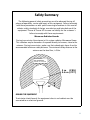
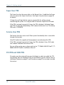
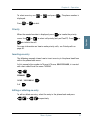
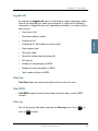
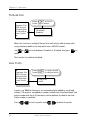
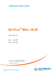
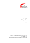
Microwave Radiation Hazards
During transmission the antenna in this system radiates Microwave Power.
This radiation may be hazardous if exposed directly to humans, close to the
antenna. During transmission, make sure that nobody gets closer than the
recommended minimum safety distance. The minimum safety distance to the
antenna on the focal line, is 3.6m.
MICROWAVE
NO PERSONNEL
based on 10W/m2
2 m (F55)
3.6 m (F77)
25°
GROUND THE EQUIPMENT
To minimize shock hazard, the equipment chassis and cabinet must be
connected to an electrical ground.
iii
DO NOT OPERATE IN AN EXPLOSIVE ATMOSPHERE
Do not operate the equipment in the presence of flammable gases or fumes.
Operation of any electrical equipment in such an environment constitutes a
definite safety hazard.
KEEP AWAY FROM LIVE CIRCUITS
Operating personnel must not remove equipment covers. Component
replacement and internal adjustment must be made by qualified
maintenance personnel. Do not replace components with the power cable
connected. Under certain conditions, dangerous voltages may exist even
with the power cable removed. To avoid injuries, always disconnect power
and discharge circuits before touching them.
DO NOT SERVICE OR ADJUST ALONE
Do not attempt internal service or adjustments unless another person,
capable of rendering first aid resuscitation, is present.
iv
Table of Contents
Chapter 1
About the Manual
Chapter 2
Introduction
The Inmarsat Fleet Service ..................................................3
The SAILOR Fleet77 system..................................................7
The SAILOR Fleet55 system ............................................... 10
Hardware Interfaces...........................................................13
The Handset...................................................................... 22
Distress Cradle .................................................................. 33
Chapter 3
Getting started
Getting ready to make a call..............................................35
Use of PIN codes. ..............................................................39
Normal calls.......................................................................41
Distress call....................................................................... 43
MPDS connection ..............................................................45
ISDN Connection ............................................................... 47
Chapter 4
Operation
Menu System ....................................................................49
Call functions ....................................................................60
Super User functions.........................................................64
Chapter 5
PC programs
System set-up using FleetCP .............................................95
v
Table of Contents
Setting up data equipment .............................................. 105
Setup using Ethernet/PPPoE............................................ 129
Chapter 6
Troubleshooting
List of Error messages...................................................... 135
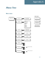
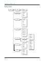
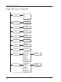
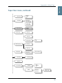
Appendix A
Menu Tree
Glossary
....................................................................................... 165
Index
....................................................................................... 169
vi
Chapter 1
About the Manual
1
Congratulations on purchasing your SAILOR Fleet product.
Whether you have chosen a TT-3084A SAILOR Fleet77 or a TT-3086A SAILOR
Fleet55, the system makes it possible for you to communicate from virtually
any ocean region in the world using the Inmarsat Fleet service established by
Inmarsat.
Both systems support high-speed data (64 kbit/s circuit switched and packet
data) and high quality voice as well as inexpensive voice services. In addition
the SAILOR Fleet77 optionally supports 128 kbit/s data service.
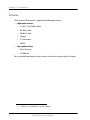
This manual has the following chapters:
•
Introduction - an overview of the Inmarsat Fleet system and its services.
•
Getting started - a description of how to make and receive calls and the use
of PIN codes.
•
Operation - a detailed description of the menu system in the BDU.
•
PC programs - a description of how to use the accompanying configuration
PC software (FleetCP) and to setup the PC for data connections.
•
Troubleshooting – a description of the most common errors, how to deal
with them and how to get further help if necessary.
Additionally you will find a glossary of abbreviations and an index at the end
of the manual.
1
Chapter 1: About the Manual
2
Chapter 2
Introduction
2
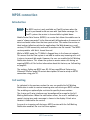
The Inmarsat Fleet Service
2.1
Overview
2.1.1
The Inmarsat Fleet service is based on 4 Geostationary 3rd generation
satellites situated above the equator, but can also operate on the new 4th
generation satellites. Geostationary means that the satellites are always
located in the same position, i.e. they rotate at the same speed as that of the
earth. Each satellite covers a certain area (footprint) and supports a number of
powerful spot-beams making the service available in virtually all ocean
regions on the earth between approximately 70°N and 70°S.
The 4 Geostationary Inmarsat Satellites
The satellites are your connection to the worldwide networks, and they are
managed by the Network Coordination Stations (NCSs), run by Inmarsat. The
primary functions of the NCSs are to constantly keep track of which terminals
are logged on to the system, and assign a free channel whenever a call is
made.
The gateway between the public network and the satellites is operated by
Land Earth Stations (LES). The LESs are run by different operators around the
world.
3
Chapter 2: Introduction
Services
2.1.2
The Inmarsat Fleet service supports the following services:
•
•
High speed services
•
2 x 64 / 2 x 56 kbit/s data1
•
64 kbit/s data
•
56 kbit/s data
•
Speech
•
3.1 kHz audio
•
MPDS
Low speed services
•
Mini-M voice
•
9.6 kbit fax
For a detailed description of each service see the last section of this chapter.
1.
4
128 kbit/s is only available on new F77 systems
The Inmarsat Fleet Service
2222
Chapter 2: Introduction
Introduction
The available services allow for a wide range of applications. Examples are
shown below.
Important
Before a terminal can be used on the network, it has to be
commissioned by one of the Inmarsat Service Providers (ISPs).
In order to use the different Inmarsat Fleet services it is
necessary to have at least one Inmarsat Mobile Number (IMN)
for each of the above mentioned services. In case all 8 services
are commissioned on your terminal, you will have 8 IMN
numbers.
Calling an Inmarsat Fleet terminal corresponds to making international calls.
If the satellite region/area is not known for the terminal the “country” code for
a terminal is 870. When you dial up to an Inmarsat Fleet terminal through the
public network, you have to dial the IMN number in addition to the
international access code for Inmarsat, e.g.:
+870 600 555 555
Making calls from an Inmarsat Fleet terminal corresponds to making
international calls, meaning you must always dial the country code.
The Inmarsat Fleet Service
5
Chapter 2: Introduction
Service explanation
2.1.3
The low speed services have a lower tariff than the high speed services,
because the high speed services are high quality audio or high speed data
services that require more bandwidth.
6
•
The 128 kbit/s UDI (Unrestricted Digital Information) service enables 2 x 64
kbit/s or 2 x 56 kbit/s bidirectional transmission of data to and from
terrestrial ISDN networks
•
The 64 kbit/s UDI (Unrestricted Digital Information) service enables the
bidirectional transmission of data to and from terrestrial 64 kbit/s ISDN
networks. The 56 kbit/s UDI service is similarly used to make a connection
to 56 kbit/s ISDN networks, which are primarily used in North America.
•
The Speech and 3.1 kHz audio services make it possible to establish high
quality analogue connections of a quality equal to terrestrial analogue
connections via digital networks/switches. The Speech service is used for
high quality voice connections, whereas 3.1 kHz audio can be used to
transfer analogue signals between fax machines and modems with an
analogue 2-wire interface. The 3.1 kHz audio service is transparent, and is
suitable for all analogue applications including secure telephones.
•
The MPDS service is a packet data service where the tariff depends on the
amount of data sent and received. This service is a more cost-effective
solution for web browsing, and other applications where there is no need
for constant transmission of data in both directions. It is also suitable for
applications where a constant connection is required, because the user is
no longer charged the “per minute rate”.
•
The Mini-M voice service is only for voice transmission. The voice
transmitted over the satellite is subject to a compression process that
reduces the bandwidth to 4.8 kbit/s and consequently reduces the cost.
•
The 9.6 kbit Fax allows you to send and receive fax messages using a
standard office fax machine. This service replaces the previous Mini-M fax
service. Using this service is usually more cost effective compared to the
3.1 kHz audio service.
The Inmarsat Fleet Service
2222
Chapter 2: Introduction
Overview
2.2
2.2.1
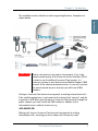
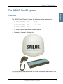
The SAILOR Fleet77 System includes the following system components:
•
TT-3008C SAILOR Fleet77 Antenna (ADU)
•
TT-3038C SAILOR Fleet77 Electronics Unit (BDU)
•
TT-3622B SAILOR Fleet77 Distress Cradle
•
TT-3620F SAILOR Fleet Control Handset (4 wire)
•
Accessories (manual, software, etc.)
For instructions on how to assemble the system, wiring and specifications, see
the Installation Manual.
The SAILOR Fleet77 system
7
Introduction
The SAILOR Fleet77 system
Chapter 2: Introduction
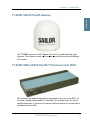
TT-3008C Antenna
2.2.2
The TT-3008C antenna or ADU (Above Deck Unit) is a stabilized high-gain
antenna. The antenna contains all functions for satellite tracking including a
GPS system.
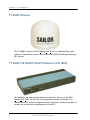
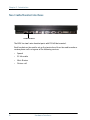
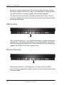
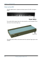
TT-3038C-128 SAILOR Fleet77 Electronics Unit (BDU)
All connectors for external equipment are placed on the rear of the BDU
(Below Deck Unit). On the front a configuration module is attached. This
module stores all system configuration data. It contains all necessary data to
recover the system after a replacement of the BDU.
8
The SAILOR Fleet77 system
2.2.3
2222
Chapter 2: Introduction
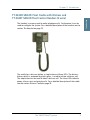
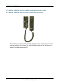
2.2.4
The handset is primary used to make telephone calls. Furthermore it can be
used to configure the system. For a detailed description of the handset see the
section The Handset on page 22.
The cradle has a distress button, a stop button and three LEDs. The distress
button, which is protected by plastic glass, is used to initiate a distress call.
The stop button can be used to abort a distress call. The three LEDs indicate
power, distress test and priority calls. For a detailed description of the cradle
see the section Distress Cradle on page 33.
The SAILOR Fleet77 system
9
Introduction
TT-3622B SAILOR Fleet Cradle with Distress and
TT-3620F SAILOR Fleet Control Handset (4 wire)
Chapter 2: Introduction
The SAILOR Fleet55 system
Overview
2.3
2.3.1
The SAILOR Fleet55 System includes the following system components:
•
TT-3008F SAILOR Fleet55 Antenna (ADU)
•
TT-3038C-WMx SAILOR Fleet55 Electronics Unit (BDU)
•
TT-3622C SAILOR Fleet Cradle without Distress
•
TT-3620F SAILOR Fleet Control Handset (4 wire)
•
Accessories (manual, software, etc.)
For instructions on how to assemble the system, wiring and specifications, see
the Installation Manual.
10
The SAILOR Fleet55 system
2222
Chapter 2: Introduction
2.3.2
Introduction
TT-3008F SAILOR Fleet55 Antenna
The TT-3008F antenna or ADU (Above Deck Unit) is a stabilized high-gain
antenna. The antenna contains all functions for satellite tracking including a
GPS system.
TT-3038C-WMx SAILOR Fleet55/77 Electronics Unit (BDU)
2.3.3
All connectors for external equipment are placed on the rear of the BDU. On
the front a configuration module is attached. This module stores all system
configuration data. It contains all necessary data to recover the system after a
replacement of the BDU.
The SAILOR Fleet55 system
11
Chapter 2: Introduction
TT-3622C SAILOR Fleet Cradle without Distress and
TT-3620F SAILOR Fleet Control Handset (4 wire)
The handset is primarily used to make telephone calls. Furthermore it can be
used to configure the system. For a detailed description of the handset see
section The Handset on page 22.
12
The SAILOR Fleet55 system
2.3.4
2222
Chapter 2: Introduction
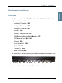
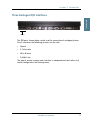
2.4
Overview
2.4.1
The Electronic Units of the SAILOR Fleet77 and the SAILOR Fleet55 have the
following hardware interfaces:
•
Analogue RJ11 number 1 (X1)
•
Analogue RJ11 number 2 (X2)
•
Analogue RJ11 number 3 (X3)
•
Handset 1 (X4)
•
Handset 2 (X5) (For future use)
•
ISDN (Integrated Services Digital Network) (X7)
•
USB (Universal Serial Bus) (X8)
•
Ethernet (X9)
•
Serial connector 1 (X10)
•
NMEA 0183 (X11)
•
4 Discrete I/O (X12)
•
Power Connector (X13)
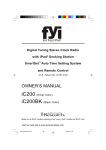
All connectors for these interfaces are found on the rear of the Electronic Unit:
X1 X2 X3
X4
X5
X6 X7 X8
X9
X10
X11
X12
X13
These interfaces can be used for the different Inmarsat Fleet services.
Hardware Interfaces
13
Introduction
Hardware Interfaces
Chapter 2: Introduction
Two Cradle/Handset interfaces
2.4.2
Cradle/Handset
The BDU has two 4 wire handset ports with RS-485 data control.
Each handset can be used to set up the terminal and it can be used to make or
receive phone calls using one of the following services:
14
•
Speech
•
3.1 kHz audio
•
Mini-M voice
•
Distress call
Hardware Interfaces
2222
Chapter 2: Introduction
2.4.3
Introduction
Three Analogue RJ11 interfaces
RJ11
The RJ11 ports shown above can be used for connection of analogue phones.
For all interfaces the following services can be used:
•
Speech
•
3.1 kHz audio
•
Mini-M voice
•
9.6 kbit/s fax
The type of service used on each interface is independent of each other and
can be configured in the Routing menu.
Hardware Interfaces
15
Chapter 2: Introduction
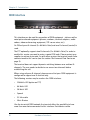
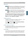
ISDN interface
2.4.4
ISDN
This interface can be used for connection of ISDN equipment – data as well as
voice/picture based equipment (phones, modems, terminal adapters, audio
codecs, video conferencing equipment, STE secure voice, etc.).
On F55 only one B-channel (1 x 64 kbit/s Data) and one D-channel (control) is
used.
The F77 optionally supports two B-channels (2 x 64 kbit/s Data). In order to
enable this service you need to enter a special PIN code. Please contact your
supplier to retrieve a pin code. As with other services the terminal needs to be
commissioned to this service (see the section The Inmarsat Fleet Service on
page 3).
The terminal does not support dynamic switching between one and two Bchannels. The user needs to decide to use one or two channels before
establishing the call.
When using only one B-channel, please ensure that your ISDN equipment is
configured to support one B-channel only.
The following services may be used on the ISDN interface:
•
128 kbit/s UDI (option on F77)
•
64 kbit/s UDI
•
56 kbit/s UDI
•
Speech
•
3.1 kHz audio
•
Mini-M voice
Like the terrestrial ISDN network the terminal offers the possibility to have
more than one device connected to this interface. Each device can be
16
Hardware Interfaces
2222
Chapter 2: Introduction
Note
Introduction
individually addressed when called, and the service type can be selected
individually. This requires that the attached equipment supports MSN
(Multiple Subscriber Number). Depending on the brand of equipment it may
be possible to program the equipment with more MSNs. If a device should
respond to a certain IMN number, it must be programmed in the ISDN
equipment using the IMN as MSN. Note that the equipment will only react if
both MSN and service type (speech, 3.1 kHz audio, 128 kbit/s, 64 kbit/s or 56
kbit/s) fit the ISDN equipment.
When the 128 kbit/s service is not used, the ISDN interface supports
data transmission of one B-channel at 64 or 56 kbit/s as opposed to
two B-channels at 64 or 56 kbit/s available on the terrestrial ISDN
network.
When using satellite equipment a delay is introduced due to the satellite link.
Not all standard ISDN devices are equally good at coping with this.
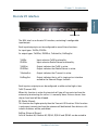
RS-232 interface
2.4.5
RS-232
The RS-232 interface is a standard 9-pin serial ports, with a maximum port
speed of 115.2 kbit/s. The interface supports the following service types:
•
MPDS service
•
Configuration of the terminal via FleetCP software (See the section System
set-up using FleetCP on page 95)
•
Connection of an IP Router
•
64 kbit/s UDI using RS-232
When using the FleetCP program, the PC must be connected to the RS-232
interface.
Hardware Interfaces
17
Chapter 2: Introduction
NMEA 0183 interface
2.4.6
NMEA 0183
The NMEA 0183 interface is a Gyro and Navigation interface. It connects to a
backup GPS antenna, which provides GPS information for the system when the
built-in GPS receiver of the antenna cannot obtain GPS fix.
18
Hardware Interfaces
2222
Chapter 2: Introduction
2.4.7
Introduction
Discrete I/O interface
Discrete I/O
The BDU also has a discrete I/O interface, containing 4 configurable
input/output.
Each input/output pin can be configured to one of these functions:
As input types: TxOffIn, RSOffIn
As output types: TxOffOut, RSOffOut, TxActiveOut, ExtRingOut
TxOffIn:
RSOffIn:
Input activates TxOff functionality.
Input activates Radio Silence functionality.
TxOffOut:
RSOffOut:
Output indicates that TxOff is active.
Output indicates that Radio Silence is active.
TxActiveOut:
Output indicates that Transmit is active.
ExtRingOut:
Output indicates that a call is ringing at an interface
routed to the External Ringer function.
Each input or output pin can be configured as either active high or low.
TxOff (Transmit Off):
When this function is active the terminal will stop all transmission from the
antenna by terminating the call as it is normally done. Distress alarms from
ship or from land will be allowed.
RS (Radio Silence):
This function has higher priority than the Transmit-Off function. If this function
is active any transmission from the antenna will be blocked. Even distress calls
in both directions will be prohibited.
ExtRing (External Ringer):
Calls to Handset #1, Handset #2, RJ11 #1, RJ11 #2 and RJ11 #3 can be routed to
Hardware Interfaces
19
Chapter 2: Introduction
an external ringer connected to an I/O pin with the External Ringer function.
The output signal for the external ringer is activated when an incoming call to
the routed interface is received (ringing). See Routing on page 66.
The above functions can only be activated by the discrete I/O pins. The pins
have to be configured from the Super User menu, which can only be accessed
by entering a password.
USB Interface
2.4.8
USB
USB - Universal Serial Bus – is an interface that allows a single universal plug
to connect PCs. USB replaces the different serial and parallel PC connections
with one standard plug-and-play port. Please note that the USB interface only
supports the 64 kbit/s UDI service at present time.
Ethernet Interface
2.4.9
LAN
The Ethernet interface is a RJ45 connector. It can be used for the MPDS
service. Connect a computer through a switch or hub or connect directly using
a crossover cable.
20
Hardware Interfaces
2222
Chapter 2: Introduction
2.4.10
Introduction
Power Connector
Power
The Power connector must be connected to a 24 V DC floating power supply.
For information on how to connect power, see the Installation Manual.
Hardware Interfaces
21
Chapter 2: Introduction
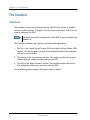
The Handset
2.5
Overview
2.5.1
The handset is the primary interface for the SAILOR Fleet system. It enables
the user to dial numbers, it displays error and status messages, and it can be
used to configure the BDU.
Note
The menu system for configuration of the BDU is only available from
Handset #1.
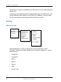
The handset is divided into 3 distinct and inter-working sections.
1. The first is the Liquid Crystal Display (LCD) and Light Emitting Diodes (LED)
section. This section gives the user visual indications about the operation
and status of the system.
2. The second is the Function keys section. This section enables the user to
interact with the software menu system of the BDU.
3. The third is the Alpha-Numeric section. This section enables the user to
dial and perform data entry functions into the BDU.
In the following these sections will be described in details.
22
The Handset
2222
Chapter 2: Introduction
2.5.2
Introduction
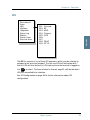
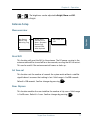
LCD/LEDs
LCD
As shown in the picture above, the top of the handset contains the LCD for
displaying information to the user. It can be adjusted for contrast and is
backlit for viewing in dim light or at night.
The LCD display is graphically shown below:
Scroll Up
Text
Area
Scroll
Down
Mailbox
Signal Strength
IOR:SINGAPOR
Ready
Speaker
Enabled
Handset
Off hook
Secondary
Functions
Enabled
More Options
Available
Pin Code
Locked
Enabled
Alphabetic
Entry Enabled
Locked
The display contains a set of symbols which together with the 4 indicators
below the display gives continuous indication of current status.
The Handset
23
Chapter 2: Introduction
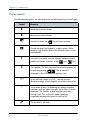
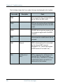
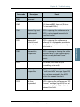
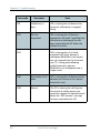
Display symbols
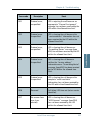
The table below explains the meaning of the symbols appearing in the display.
Symbol
Meaning
More menu entries above.
More menu entries below.
Turned on when the
key has been pressed.
Turned on when the keypad is in alpha mode. Alpha
mode is used to enter letters (for example names in the
phone book).
The value in a menu must be selected between certain
predefined values by means of the
and
keys.
The speaker. The user can turn the external speaker on
and off by pressing
8 . The symbol is
displayed in the LCD when the speaker is on.
24
Short message stored at a LES – see the sections
Mailbox on page 54 and page 82 for further information.
The number of bars () following this antenna symbol
indicates received signal strength. Up to 5 bars may be
displayed. The number of displayed bars may vary
during a call. This is due to a power reduction,
negotiated between the terminal and the LES.
The handset is off hook.
The Handset
2222
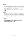
LEDs
There are four LEDs below the LCD display (see below). From left to right they
are Power (GREEN) – Alarm (RED) – Call (AMBER) – Link (GREEN).
Link
Power
Alarm
Call
POWER LED (GREEN): The Power LED indicates that the system has power.
ALARM LED (RED): The Alarm LED indicates that the system has detected a
fault. If the LED is lit the error can be examined in the Alarm log. See the
section Alarm Log on page 55.
CALL LED (AMBER): The Call LED flashes when a call is ringing at the
receiving end and lights constantly when a connection is made.
LINK LED (GREEN): The Link LED indicates that the system is receiving from a
satellite. Note that the LED may not light constantly, because the satellite may
not be transmitting constantly during a call.
The Handset
25
Introduction
Chapter 2: Introduction
Chapter 2: Introduction
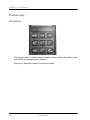
Function keys
2.5.3
Introduction
The Function keys, as shown above, enable the user to enter the menu system
of the BDU and change various settings.
Each key is described in detail in the next section.
26
The Handset
2222
Chapter 2: Introduction
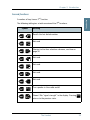
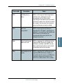
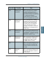
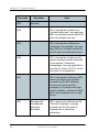
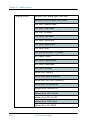
Key description
Symbol
Menu
Introduction
Each key is described in detail below.
Meaning
Menu key: Enters the top level of the menu system. See the
section Menu System on page 49.
The key can also be used to switch the terminal on and off.
To switch on the terminal press the key shortly.
To switch off the terminal press the key for a while and check that
the LCD display counts down to zero before releasing the key.
Exit
OK
C
EXIT key: Similar in function to the Esc-key on a PC. While in the
menu system, pressing Exit will bring the user back one level
until the menu is completely exited. When asked YES or NO by
the system, pressing Exit will be interpreted as a NO response.
When entering data into the BDU, pressing exit will cancel the
entry.
OK key: The opposite of the Exit key. It is similar in function to the
Enter key on a PC. When in the main screen display, pressing OK
will enter the menu system. While in the menus, pressing OK will
enter the selected menu. When entering data, such as phone
numbers or PIN codes, pressing OK will accept the entry.
Clear key: This is a dual function key. The primary function is to
clear the last entered digit. It is similar in function to the
backspace key on a PC.
Secondary function: INSERT. This function is accessed by first
pressing and releasing the
key and then pressing C .
The insert function is used to insert new Inmarsat Mobile
Numbers (IMNs) into the terminal, insert Phone book entries, etc.
The Handset
27
Chapter 2: Introduction
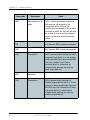
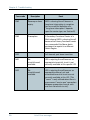
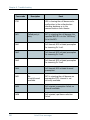
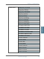
Symbol
Meaning
SCROLL UP key: Also a dual function key. The primary function is
to enable the user to scroll up to menu items not shown on the 2line display of the LCD.
Secondary function: Edit. Allows users to edit previously entered
information in the BDU.
ABC key: Toggles between normal mode and alpha numeric
mode.
Secondary function: Delete. Allows users to delete previously
entered information.
When browsing in the menu system this key can also be used to
toggle the short codes on/off. This feature also includes toggling
displaying of the short codes on/off. These codes can be used as
shortcut to a given menu item by pressing the short code number
using the numeric keys.
2nd key: The 2nd function will be applied to the next key. See
below.
SCROLL DOWN key: Is used to scroll down to menu items not
shown on the 2-line display of the LCD.
Toggles between on hook and off hook.
28
The Handset
2222
Chapter 2: Introduction
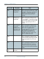
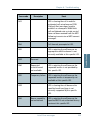
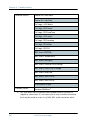
Second functions
Introduction
A number of keys have a 2nd function.
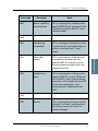
The following table gives a total overview of the 2nd functions.
Symbol
Meaning
Recalls the last dialed number.
Not used
2
Shortcut to the Area selection submenu, see Area on
page 52.
3
Not used.
4
Not used.
5
Not used.
6
7
8
Not used.
pqrs
Turn speaker in the cradle on/off.
Shows C/No “signal strength” in the display. Pressing
returns to the previous state.
The Handset
Exit
29
Chapter 2: Introduction
Symbol
#
0
C
Meaning
Sets the brightness of the LEDs. See LED Dimm on page 76.
Shortcut to the Help desk menu. See Help Desk on page 55.
Insert an entry (for example in phone book)
Edit an existing entry (for example in phone book)
Delete an existing entry (for example in phone book)
30
The Handset
2222
Chapter 2: Introduction
2.5.4
Introduction
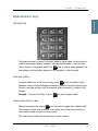
Alpha-Numeric keys
Introduction
The keypad can be in normal (numeric) mode or alpha mode. Normal mode is
used to enter digits (phone numbers) whereas alpha mode is used to enter
letters (names in the phone book). The
key is used to switch between the
two modes and the display indicates if the keypad is in alpha mode.
Entering letters
In alpha mode each of the numeric keys (plus # ) can be used to select
between subsets of the alphabet (and certain special characters) by pressing
the key a number of times until the wanted letter/character is shown on the
display.
Example: To insert the letter C, press 2
3 times in alpha mode.
Using menu short codes
When browsing in the menus
can be used to toggle short codes on/off.
These codes can be used as shortcut to a given menu item by pressing the
short code number using the numeric keys.
The next section shows the relevant keys in alpha mode.
The Handset
31
Chapter 2: Introduction
Available functions in alpha mode
The table below shows the available key functions in alpha mode.
Key
Available characters or functions in alpha mode
-?!,.:’$()+/1
2
ABC2
3
DEF3
4
GHI4
5
JKL5
6
MNO6
7
8
pqrs
PQRS7
TUV8
WXYZ9
32
0
Move cursor (forced)
#
<space>
The Handset
2222
Chapter 2: Introduction
Introduction
Note
2.6
2.6.1
The Distress cradle is only available with the TT-3084A SAILOR
Fleet77 system.
Besides being the base for the handset, the Distress cradle is also where a
Distress call is initiated or ended.
A speaker for hand free operation is located in the lower left side of the cradle.
Press
8
on the handset to toggle the speaker on/off.
Distress Cradle
33
Introduction
Distress Cradle
Chapter 2: Introduction
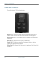
Cradle LEDs and buttons
2.6.2
The cradle includes 3 LEDs and two buttons.
Distress button: The Distress button, which is protected by plastic glass, is
used to initiate a Distress call. See To make a Distress call. on page 43.
Distress Stop button: Is used to abort a distress call before the connection is
established.
Power On LED: Indicates that the system is powered on.
Priority Call LED: Indicates a priority call in progress (distress, safety or
urgency). See Priority calls on page 62.
Distress Test LED: Indicates that a distress test is performed. See DistressTest
on page 79.
34
Distress Cradle
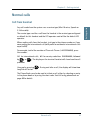
Chapter 3
Getting started
3
Getting ready to make a call
3.1
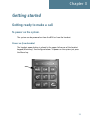
To power on the system.
3.1.1
The system can be powered on from the BDU or from the handset.
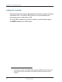
Power on from handset
The handset power button is placed in the upper left corner of the handset
keypad (Menu key). See the figure below. To power on the system just press
the Menu key.
35
Chapter 3: Getting started
Power on from BDU
The BDU power button is placed on the back panel of the BDU. See figure
below.
Press and hold the power button for a few seconds or until the green LED on
the front of the terminal lights up.
Power LED
The display and all LEDs on the handset and the cradle will light up for a few
seconds.
36
Getting ready to make a call
3333
Chapter 3: Getting started
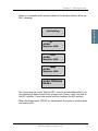
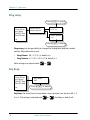
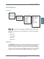
Below is an example of the normal readout of the handset display, while the
BDU is booting.
Getting started
Initialising
AORE:
Wait for NCS
AORE:
Wait for NCS
AORE:
Wait for GPS
AORE: LESNAME
READY
The system may stay in the “Wait for GPS” state for an extended period, if e.g.
the antenna has been turned off for a long time or there is not a free view to
the GPS satellites. It may take several minutes to obtain the GPS position.
When the display reads “READY” as shown above, the system is ready to make
and receive calls.
Getting ready to make a call
37
Chapter 3: Getting started
To power off the system.
3.1.2
The system can be powered off from the BDU or from the handset.
Power off from handset
The handset power button is placed in the upper left corner of the handset
keypad (Menu key).
To power off the system just press and hold the key. After a few seconds the
LCD display starts a count down to zero. When the countdown is finished the
display shows the message “Release Power Button”. Release the key and the
system will power off.
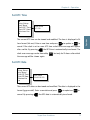
Power off from BDU
Press and hold the power button for a few seconds, until the handset display
shows the message shown below.
Thrane F77
Goodbye
Thrane F55
Goodbye
Release the button and the terminal will shut down.
Note
38
Wait at least 5 seconds after a power down, before trying to power
up the system again.
Getting ready to make a call
3333
Chapter 3: Getting started
Overview
3.2
3.2.1
Access to some of the functions is restricted by a PIN code. Two different kinds
of User PIN codes are used in the system: One PIN for the Super User and one
for the Service User.
Common for both PIN types is that the length must be between 4 and 8 digits
and that they contain digits between 0 and 9.
The normal everyday user (Normal User) can make and receive calls, access
the phone book, choose an ocean region and a default LES, read the alarm log
and status and make a call from the Helpdesk. For a description of these
functions see Menu System on page 49. All other setup changes have to be
carried out by a Super User or a Service User.
Use of PIN codes.
39
Getting started
Use of PIN codes.
Chapter 3: Getting started
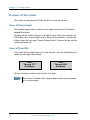
Super User PIN
3.2.2
The Super User has the same rights as the Normal User. In addition the Super
User can access the Super User menu. See Super User functions on page 64
for details.
A Super User will typically be a person responsible for setting up and
maintaining the system. It is only possible to have one Super User PIN code.
If the PIN is entered incorrectly 3 times, the PIN is blocked. A blocked Super
User PIN can only be unblocked by a PUK code or the Service User. The factory
PIN code is ‘12345678’.
Service User PIN
3.2.3
The Service User has access to all Fleet system functionality that is accessible
through the handset.
Only T&T and/or the supplier of the equipment normally know this PIN.
If the PIN is entered incorrectly 3 times, the PIN is blocked. Only a PUK code
can unblock a blocked Service User PIN.
For use of the service menu, please refer to the “TT-3084A SAILOR Fleet77, TT3086A SAILOR Fleet55, Installation Manual”.
STU PIN and 128K PIN
3.2.4
Pin codes must be retrieved from your distributor in order to enable the STU
functionality (Secure Telephone Unit) or the 128 kbit/s service. Please refer to
Additional Features on page 87 and Pin codes on page 97 to see how to enable
the service.
40
Use of PIN codes.
3333
Chapter 3: Getting started
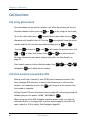
Call from handset
3.3
3.3.1
Any call made from the system uses a service type (Mini-M voice, Speech or
3.1 kHz audio).
The service type used for a call from the handset is the service type configured
as default for this handset and the LES operator used will be the default LES
operator.
When making calls from the handset, just type in the phone number as if you
were making an international call (with prefix for automatic international calls
equal to 00).
For example, to dial the number of Thrane & Thrane (+45 39558800), press
the number:
00 for international calls, 45 for country code then 39558800, followed
by
or #
proceeds.
. The display on the terminal handset will show how the call
Hang up by pressing
long the call lasted.
. During and after a call, the display will show how
The Phone Book can also be used to initiate a call, either by selecting an entry
in the phone book or by using the short code. See Call using phone book on
page 60 for details.
Normal calls
41
Getting started
Normal calls
Chapter 3: Getting started
Calling the terminal
3.3.2
Calling the terminal or a device connected to the terminal is similar to making
international calls. The specific IMN-number1 has to be preceded by the
international access code, which is 870.
To call the IMN-number on a terminal situated in any of the ocean regions,
dial 00870 followed by the IMN number.
1.
42
A terminal may have more IMN numbers, because different services exist and
more devices may be connected to the different hardware interfaces of the
terminal.
Normal calls
3333
Chapter 3: Getting started
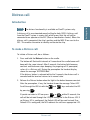
Introduction
Note
3.4
3.4.1
Getting started
Distress call
The distress functionality is available on Fleet77 systems only.
A distress call is an automated way of calling for help (SOS). A distress call
from the Fleet77 system is a voice call, which means that the call will be
connected to an operator at the RCC (Rescue Coordination Center). When the
distress call is connected, the ship’s position and the MES ID are sent to the
RCC. This enables the center to identify and locate the ship.
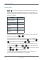
To make a Distress call.
3.4.2
To initiate a Distress call, do as follows:
1. Press and hold the Distress button on the cradle.
The button will flash with intervals of 1 second and the cradle buzzer will
beep with the same interval. After 5 seconds, the button light becomes
constant and the buzzer stops beeping. Any ongoing call is preempted,
unless it is a Distress call. During the preemption the handset display
shows the message ‘DISTRESS Wait’.
If the distress button is released within the 5 seconds, the distress call is
canceled and the terminal returns to its normal state.
2. Release the Distress button when the light in the button becomes constant.
After the preemption, if any, the handset shows the message ‘Select LES’.
Scroll through the LES list with the
by pressing
OK
and
keys and select the LES
.
If you do not select a LES nor press #
or
within 15 seconds, the
call will be initiated through the LES pre-configured in the Distress LES. If
no Distress LES is configured, the Default LES will be used instead. If no
Default LES is configured, the NCS redirects the call to an appropriate LES.
Distress call
43
Chapter 3: Getting started
Note
If a Distress LES is not defined for each Ocean Region, an alarm
will appear and the entry ‘Distress LES is not selected in all
Ocean Regions’ will be added to the alarm log.
To cancel the Distress mode, press and hold the Distress Stop button, after
the button light becomes constant, but before the 15 seconds timer runs
out. The display will then show Distress Aborted.
If the Distress call is continued, the handset will display DISTRESS Calling. The call will be connected to the RCC, the handset will display
DISTRESS - Connected and the cradle LED ‘Priority call’ will light
up. You can now make the Distress call
3. Use the handset to talk to the RCC operator.
The ‘Distress’ button light will stay on until the call is aborted.
Distress call failure.
3.4.3
If the Distress call fails to connect due to a system malfunction (BDU, ADU,
satellite or terrestrial), the light in the cradle ‘Distress’ button will turn off and
the system will return to a normal state.
Distress and Priority call to the ship
3.4.4
The RCC operator can generate a distress alert priority call to the ship. The
‘Priority Call’ LED will start flashing on all cradles, and if the call has distress
priority the buzzer will beep with 1 second intervals. Any calls with lower
priority, including MPDS sessions, are preempted and a busy tone is heard.
Answer the distress and priority call by picking up a handset or by pressing
after which the ‘Priority Call’ LED will light steadily and the buzzer stops
beeping.
The ‘Priority Call’ LED is turned off when the call is terminated.
If the call is not answered by the ship, but terminated by the RCC, the Alarm
LED turns on to indicate that there was an unanswered distress alert or priority
call. Details about the alarm can be checked in the alarm log.
44
Distress call
3333
Chapter 3: Getting started
Introduction
Note
3.5
3.5.1
The MPDS service is only available on Fleet55 systems when the
vessel is positioned inside an area with Spot Beam coverage. On
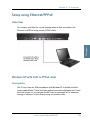
Fleet77 systems the service is also available in global beam.
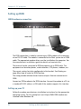
Mobile Packet Data Service (MPDS) is a service that allows the mobile user to
remain “always connected” to the Internet with billing based on the amount of
data transferred rather than the time spent online. This makes the service an
ideal and cost effective solution for applications like Web browsing, e-mail
services, IP/LAN connectivity and small to medium size file transfer. The MPDS
service provides a 64 kbit/s shared channel.
While in MPDS mode the TT-3084A is flagged busy in the Inmarsat network.
This means that the Fleet system is not able to receive any incoming calls until
it returns to normal idle mode. However, the user can enable the Call Waiting
Notification feature. This allows the system to receive voice calls during an
ongoing MPDS call. For further information about this feature, see Call waiting
on page 45.
The sections Setting up MPDS over RS-232 on page 105 and Setup using
Ethernet/PPPoE on page 129 contain descriptions of how to setup an MPDS
connection using your PC.
Call waiting
3.5.2
As indicated in the previous section the user can enable the Call Waiting
Notification in order to receive incoming voice calls during an MPDS session.
The enabling can optionally be restricted to specific phone numbers.
The 4-wire and 2-wire interfaces can be configured for usage for the Call
Waiting Notification. When the notification arrives, the user is notified by a
special ringing tone and a message is shown in the display if the 4-wire
handset is selected for the service.
In case of an incoming call during an MPDS session with the Call Waiting
Notification enabled, the user has three options:
MPDS connection
45
Getting started
MPDS connection
Chapter 3: Getting started
•
The user can reject the preemption of the MPDS connection by pressing
*
or
Exit
on the 4-wire handset (if enabled) or by taking an enabled
2-wire phone off hook, pressing * and placing the phone on hook
again. The ringing stops on all handsets that are configured for the
service.
•
The user can accept the preemption of the MPDS connection by pressing
OK
or #
on the 4-wire handset (if enabled) or by taking an enabled
and placing the phone on hook
2-wire phone off hook, pressing #
again.
The MPDS session is now deregistered and the call gets through after a
short while. The phone to which the call is routed starts ringing and the
call can be answered. Note that the call can be answered on another
interface than the interface that was used to accept the call – e.g. a fax will
normally only be routed to a specific RJ11 connector and not the 4-wire
handset.
•
The user may also choose to do nothing. After a certain time the
notification stops and the preemption of the MPDS connection is implicitly
rejected, if no other lines have accepted the notification.
Configuration of the Call Waiting notification is described in Call Waiting
Notification on page 89.
46
MPDS connection
3333
Chapter 3: Getting started
Introduction
Note
3.6
3.6.1
Getting started
ISDN Connection
The ISDN service is only available on Fleet55 systems when the
vessel is positioned inside an area with Spot Beam coverage. On
Fleet77 systems the services are also available in global beam.
Though 128K can not be guaranteed by INMARSAT.
The Integrated Services Digital Network (ISDN) enables a bidirectional
transmission of data to and from terrestrial ISDN networks.
The mobile ISDN service is charged by connection time. That makes the service
feasible for transmissions that require a large data throughput.
The section Setting up ISDN on page 112 contains a description of how to setup
an ISDN data connection on your PC.
Supported services
3.6.2
The Fleet55 and the generic Fleet77 support a single B-channel (1 x 64 kbit/s
Data) and one D-channel (control).
The Fleet77 optionally supports two B-channels (2 x 64 kbit/s Data). In order to
enable this service a pin code is needed. This pin code can be retrieved from
your distributor. As with other services the terminal needs to be commissioned
to the 128 kbit/s service.
The terminal does not support dynamic switching between one and two Bchannels. The user needs to decide whether to use one or two channels before
establishing the call. The Fleet77 128 kbit/s service does not support mixed
fixed and mobile originated calls, mixed UDI and voice calls nor the ability to
close down one of the B channels dynamically.
For fixed originated calls, the terrestrial user is expected to dial the same INM
number twice for each of the 64kbit/s calls.
Please refer to ISDN interface on page 16 for additional information about the
ISDN interface.
ISDN Connection
47
Chapter 3: Getting started
48
ISDN Connection
Chapter 4
Operation
4
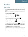
Menu System
4.1
This section describes the functions in the menu system that are available to
all users.
The menu items concerning Distress/Priority call options are only present on
Fleet77 systems.
.
•
To access the menu, press
•
To scroll through the menus, press
•
To enter the selected menu, press
•
To exit to the previous level in the menu system, press
•
To reach a specific menu item, press
Menu
to the entry level. E.g. pressing
menu.
•
or
OK
Menu
.
.
Menu
5
Exit
.
and a number corresponding
will access the 'Alarm Log'
To toggle shortcut numbers on and off, pressing
in the menu system.
The level of access to the menus is divided into 3 groups of users. A Normal
User, a Super User and a Service User.
The Normal User has access to normal everyday functions.
A Super User has the same rights, but can additionally access different setup
menus.
The Service User menu can only be accessed by the supplier or Thrane &
Thrane. The Super User and Service User menus are protected by PIN codes.
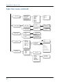
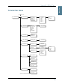
A complete Menu Tree can be found in Menu Tree on page 157.
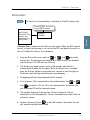
49
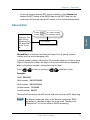
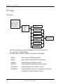
Chapter 4: Operation
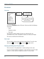
Phonebook
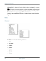
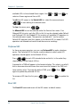
4.1.1
Overview
Phonebook
Area
LES
Mailbox
Helpdesk
Alarm log
Status
Super User
Service User
01 TT
02 TT2
01 539558800
02 5395588xx
Hint
Press
to view the
last nine digits of the
phonenumber
The terminal PhoneBook contains 99 entries. Each entry holds the following
information:
•
Name
•
Telephone number
•
Short code
The telephone number includes call prefix for automatic calls and
international access code. The telephone number can hold up to 22 digits.
The name can hold from 0 to 16 characters.
Short code
The short code can be used for quick access when dialing. To use the short
code, press *
<short code> #
and press #
again to dial.
Viewing and dialing from the phone book
The list of entries in the phone book is sorted according to short code.
An entry in the phone book is displayed as a short code and a name if in alpha
mode or as a short code and a telephone number if in normal mode.
50
Menu System
or #
Press
or
and press
to dial.
Priority
When the wanted number is displayed, press
menu. Use
OK
OK
. The phone number is
to invoke the priority
to select call priority (only on Fleet77). Press #
or
or
to initiate the call.
For more information on how to make priority calls, see Priority calls on
page 62.
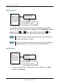
Inserting an entry
The following example shows how to insert an entry in the phone book from
within the phone book menu.
In this example the number to Thrane & Thrane, 004539558800, is inserted
with short code 14 and the name THRANE.
C
THRANE
OK
0045 39558800
14
OK
OK
Editing or deleting an entry
To edit or delete an entry, select the entry in the phone book and press
or
respectively.
Menu System
51
Operation
To select an entry, use
displayed.
4444
Chapter 4: Operation
Chapter 4: Operation
Area
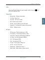
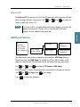
4.1.2
Phonebook
Area
LES
Mailbox
Helpdesk
Alarm log
Status
Super User
Service User
None
*Automatic
W-Atlantic
E-Atlantic
Pacific
Indian
Spare1
Spare2
Spare3
Spare4
The Area menu is used to select ocean region and has the following list of
possible choices:
•
None
•
Automatic
•
W-Atlantic
•
E-Atlantic
•
Pacific
•
Indian
•
Spare 1
•
Spare 2
•
Spare 3
•
Spare 4
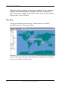
The selected area is marked with an *. If Automatic is selected the terminal
will determine the area by scanning the sky and selecting the satellite with the
best C/No. The selection is changed by choosing an area and then pressing
. Consult a coverage map to see the coverage areas for each ocean
region.
OK
52
Menu System
Phonebook
Area
LES
Mailbox
Helpdesk
Alarm log
Status
Super User
Service User
001:
002:
003:
004:
005:
006:
007:
008:
009:
.
.
.
.
Comsat
BT
KDD
Telenor
OTE
4.1.3
Operation
LES
4444
Chapter 4: Operation
FRAC
ST12
The LES list contains a list of those LES operators, which may be selected as
gateway to the terrestrial network. The last used LES will be marked with *
and this LES will also be the first LES tried next time the terminal is logged on.
Use OK to select. The Area selected in Area on page 52, will decide which
LESs will be available for selection.
See LES Configuration on page 85 for further information about LES
configuration.
Menu System
53
Chapter 4: Operation
Mailbox
Phonebook
Area
LES
Mailbox
Helpdesk
Alarm log
Status
Super User
Service User
4.1.4
List Empty
The Mailbox feature is not supported by all LES operators. The feature handles
messages sent from the LES operator. If a call is made to a terminal which is
busy, switched off, etc. the LES operator may offer the facility to record a short
message. When the terminal becomes operational again, a message is sent
indicating that the LES operator has recorded a short message for the
terminal.
The symbol in the handset display indicates the presence of such
messages.
Each message can be seen in the Mailbox menu and contains the following
information:
•
LES Access Code
•
Service type (voice, fax, data).
To view an entry, select the message and press
message in the section Call Logs on page 64.
54
Menu System
OK
. See how to delete a
Help Desk
Press
to access
the menu directly.
4.1.5
H.Desk empty
Operation
Phonebook
Area
LES
Mailbox
Helpdesk
Alarm log
Status
Super User
Service User
4444
Chapter 4: Operation
The Help Desk is a secondary phone book that can be used for storing up to 10
support phone numbers (e.g. your distributor).
Editing/inserting and deleting entries is done in exactly the same way as with
the phone book, but it can only be done from the super user menu. Each entry
contains a phone number, name of the entry, and a LES access code.
Alarm Log
4.1.6
The Alarm Log, logs all the alarms in the system. From this menu the alarms
can be viewed only. To clear the alarm list see Alarm Log on page 55. Scroll
through the list using the
or
keys. An* in front of the Alarm name
Menu System
55
Chapter 4: Operation
indicates that the alarm is still active. Select an alarm for viewing by pressing
. Each entry for an alarm contains an alarm description and the time and
date when the alarm occurred. It also includes remedies to solve the problem.
See List of Error messages on page 135 for a list of alarms.
OK
The alarm log can hold up to 20 entries. The log will wrap around when the
log is full.
Status
4.1.7
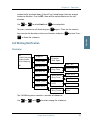
Overview
C/NO
Transiver
RF Block
Bullentin
Antenna
GPS Info
Handset
The Status menu has the following submenus:
56
•
C/No
•
Transceiver
•
RF block
•
Bulletin
•
Antenna
•
GPS info
•
Handset
Menu System
Choosing C/No will display the signal strength in dBHz. Pressing
return to the previous state.
Transceiver
•
Release date: Software release date.
•
Unit Type: Type of unit.
•
Serial No.: T&T serial number.
•
ISN: Inmarsat serial number.
•
PCB No.: Serial number of main CPU board.
•
Forward ID: The Forward ID number of the terminal.
•
SW Ver.: Software version.
Exit
will
Operation
C/No
4444
Chapter 4: Operation
RF Block
•
RX Frequency: Receiving frequency in MHz.
•
TX Frequency: Transmitting frequency in MHz
•
Freq. offset: Frequency offset between 0-1500 Hz.
•
Acc. offset: Acc offset between 0-1500 Hz.
•
AGC: AGC between 0-1024.
•
Gain: Gain between 0-256.
•
TX level: TX level equals LOW or OK.
•
Lo1-Lo3: Lox In or Out of lock.
•
Temperature: Temperature in deg. C.
•
Power mode: Power mode in sleep or normal.
Menu System
57
Chapter 4: Operation
Bulletin
•
Ocean Region: AORW, AORE, POR or IOR.
•
NSR state: Not initialized, initializing or initialized.
•
Type: Mini-M or NG
•
Bulletin page 1-6: Page 1 to 255 or Invalid.
•
Spot beam ID: Spot beam ID number between 1-255.
•
SU CC Rxed: Between 0000-9999.
•
SU CC Txed: Between 0000-9999.
Antenna
The antenna information is divided into two parts: Front End Unit and Antenna
Control Unit, and is primarily intended for service use.
FEU:
58
•
Unit type
•
Serial no.
•
SW version
•
Mode
•
Power
•
Temperature
•
Cable loss
•
Reset count
•
Date
Menu System
4444
Chapter 4: Operation
•
Unit type
•
Serial no.
•
State
•
Input power
•
Control Version
•
Loader ver.
•
FPGA ver.
•
SU ver.
•
RX2 ver.
•
Loader CRC
•
Control CRC
•
FPGA CRC
•
Config CRC
Operation
ACU:
GPS info
•
PositionInfo: Not ready or Latitude and Longitude.
•
Heading: Not ready, heading 0-360 degrees or
Heading N/A Low speed (If speed is equal to or below 1 knot).
•
Speed: Not ready or speed in knots.
•
UTC Time: Not ready or YYYY:MM:DD HH:MM:SS
•
Internal GPS: Not ready or Active and ready.
•
External GPS: Not ready or Active and ready.
Handset
This menu item shows the version of connected 4-wire handsets and cradles.
Menu System
59
Chapter 4: Operation
Call functions
4.2
Call using phone book
4.2.1
The phone book can be used to initiate a call, either by selecting an entry in
or #
the phone book and then pressing
To use the short code, press *
, or by using the short code.
followed by the short code. Pressing
afterwards will establish the call. Pressing #
instead will show the actual
or #
number and the call can then be established by pressing
Pressing
OK
or
instead of
and #
.
, will invoke the priority menu. Use
to select call priority. Press #
or
to initiate the call.
For more information on how to make priority calls, see Priority calls on
page 62.
Short code 0 contains the last dialed number, thus 0
followed by
#
or
will redial the last number.
Call from handset connected to RJ11
4.2.2
Making a call from a (normal 2-wire PSTN) phone connected to one of the
three analogue RJ11 interfaces is done in the same way as a call from the
handset. Just remember to press the #
the number is complete.
key to signal to the terminal that
Calling Thrane & Thrane in Denmark (country code 45) is done by pressing the
following keys on the phone: 0045 39558800 #
When using one of the RJ11 analogue interfaces please make sure that the
selected interface is configured for a service, which supports voice (Mini-M
voice, speech or 3.1 kHz audio). See Routing on page 66.
60
Call functions
4444
Chapter 4: Operation
The display on the terminal handset will show how the call proceeds. After
hanging up (on the 2-wire phone), the display will show how long the call
lasted.
Call from an ISDN phone
4.2.3
Making a call from a phone connected to the ISDN interface is done in the
key to
Operation
same way as a call from the handset. Just remember to press the #
signal to the terminal, that the number is complete.
To call Thrane & Thrane in Denmark (country code 45), press the following
keys on the phone:
0045 39558800 #
The display on the terminal handset will show how the call proceeds. After
hanging up (on the ISDN phone) the display will show how long the call
lasted.
Fax call
Note
4.2.4
This procedure is currently not functional in F55.
Fax calls can be made whether or not the fax has got a keypad.
Making calls from a fax with keypad connected to one of the three analogue
RJ11 interfaces is done as international calls followed by # . To call Thrane
& Thrane in Denmark (country code 45) press the following keys on the fax:
0045 39558888 #
Please make sure that the selected analogue RJ11 interface is configured for a
service which supports fax (9600 fax or 3.1 kHz audio).
The display on the handset will show how the call proceeds.
After hanging up, the display will show how long the call lasted.
Call functions
61
Chapter 4: Operation
Priority calls
Note
4.2.5
The Priority Call functionality is available on Fleet77 systems only.
A priority level can be selected when making a call. The priority levels are
listed in the table below, where Routine-personal is the lowest priority and
Distress is the highest.
Call Type
Priority level
Routine-personal
0-
Routine-professional
0+
Safety
1
Urgency
2
Distress
3
To make a Routine-personal call via the default LES, press the number and
initiate the call by pressing #
or
.
To make a Routine-personal, Routine-professional, Safety or Urgency call
using default LES, press the number followed by
keys to select call priority and press #
OK
or
. Then use the
or
to initiate the call.
To make a priority call using a LES different from the default LES, press the
number followed by
Press
. Use the
or
to open the LES list. Use the
OK
press #
OK
,
or
OK
keys to select call priority.
or
keys to select a LES and
to initiate the call.
A Distress call can only be made by pressing the Distress button on the
Distress Cradle. See To make a Distress call. on page 43.
62
Call functions
4444
Chapter 4: Operation
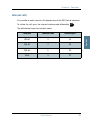
Internal calls
4.2.6
It is possible to make internal calls between any of the RJ11 (2 wire) interfaces.
To initiate the call, press the relevant interface code followed by #
.
Interface
Interface code
Interface port
RJ11 #1
2
X1
RJ11 #2
3
X2
RJ11 #3
4
X3
ISDN
5
X7
Call functions
Operation
The table below shows the interface codes.
63
Chapter 4: Operation
Super User functions
4.3
This section contains a description of the items in the Super User Menu.
Please remember that
can be used to toggle short codes on and off.
Call Logs
4.3.1
Menu overview
------------Call logs
Routing
Data Setup
Contrast
Logged Calls
Total time
Total MPDS
Clear log
Start time
Phone number
Duration
OID
Area
LES acc.code
TNID
CallPriority
Received
Transmitted
Total
The Call log menu has the following submenus
64
•
Logged calls
•
Total Time
•
Total MPDS
•
Clear log
Super User functions
Logged calls
4444
Chapter 4: Operation
•
Start time of call.
•
Destination phone number.
•
Duration of call
•
Originating ID. (Description of service used).
•
Ocean region used.
•
LES access code.
•
Terrestrial network identity (always 0).
•
Call priority.
•
Number of received bytes in MPDS.
•
Number of transmitted bytes in MPDS.
•
Total number of bytes in MPDS.
Operation
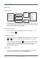
By entering the Logged calls menu it is possible to inspect information about
each of the outgoing calls made on the terminal. A subset of the following
information is logged for each call, depending on whether it is a voice call or a
data session:
Total time
Total Time shows the total accumulated call time since last reset.
Total MPDS
Total MPDS shows the total accumulated number of bytes, used in MPDS
sessions.
Clear log
The call log can be cleared by selecting the Clear Log menu. Press
clear or
Exit
OK
to
to abort.
Super User functions
65
Chapter 4: Operation
The call log can contain up to 500 entries. After that it will start overwriting the
oldest entry.
A warning is generated when the call log contains more than 470 entries. You
may then back up your log data using Fleet CP PC software. If you also clear
the log, you will get a warning again when 30 entries are left.
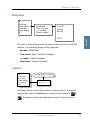
Routing
4.3.2
Menu overview
Y
Routing
Data Setup
Contrast
Handset #1
Handset #2
RJ11 #1
RJ11 #2
RJ11 #3
ISDN
RS232/USB
MiniM voice
{IMN}#
--------------Speech
{IMN}
--------------3.1 KHz Audio
*{IMN}
--------------Ext. Ringer
.
.
Z
The Routing menu is used to associate the services with one or more
interfaces. The menu has been divided into a number of submenus – one for
each interface:
66
•
Handset #1
•
Handset #2
•
RJ11 #1
•
RJ11 #2
•
RJ11 #3
•
ISDN
•
RS-232, USB
Super User functions
IMN numbers
Note
The IMN-number has to be defined before the service can be routed
to an interface. The service will not be listed in the routing table
unless it has an IMN-number defined. (Note that the External Ringer
is not a service and does not need an IMN number).
Note
Some users want the IMN number to reflect the corresponding
telephone number. In this case the user should EDIT the default IMN
number. The INSERT function is only for adding additional IMN
numbers. (or for creating the first IMN in case the list is empty).
When entering one of the above submenus it is possible to scroll through a list
of all relevant IMN-numbers for the interface. In the handset menu, you will
see all IMNs associated with voice: Mini-M voice, Speech, 3.1 kHz audio. The
ISDN menu has the same, but in addition also the services 64 kbit/s and
56 kbit/s and, if enabled, 2x64 kbit/s and 2x56 kbit/s.
Changing routing status
If an IMN has an incoming route to an interface it is marked with “*”. If it has
an outgoing route to an interface, it is marked with a “#”.
It is possible to change the routing-status for each IMN to the opposite by
pressing * for incoming and #
for outgoing. Note that the External
ringer cannot be changed; it is always an output.
Routing an IMN to more interfaces
It is possible to route one IMN to more interfaces. E.g. an IMN can be routed to
all three RJ11 interfaces at the same time. This will enable an incoming call to
be routed to three 2-wire phones simultaneously.
External Ringer
Calls to Handset #1, Handset #2, RJ11 #1, RJ11 #2 and RJ11 #3 can be routed to
an external ringer connected to the I/O interface. The output signal for the
external ringer is activated when an incoming call to the routed interface is
Super User functions
67
Operation
4444
Chapter 4: Operation
Chapter 4: Operation
received (ringing). For information on how to set up the I/O interface for the
External ringer, see I/O Setup on page 92.
Routing matrix
The table below gives an overview of the routing matrix in the Fleet system.
The Xs indicate which service can be routed to the specific interface.
Interface
Service/
Function
Mini-M voice
Handset
RJ11
(1, 2 & 3)
X
X
9600 fax
RS-232/
USB
ISDN
X
X
Speech
X
X
X
3.1 kHz Audio
X
X
X
64 kbit/s
X
56 kbit/s
X
X
Xa
MPDS
2x64 kbit/s
X
2x56 kbit/s
X
External Ringer
X
X
a. Please note that MPDS can only be associated with RS-232 and Ethernet - not
the USB interface. Ethernet is not in the list because it is always MPDS.
68
Super User functions
Routing
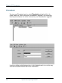
Data setup
Contrast
Ring Setup
Baudrate
Flow control
+++mode
Result codes
4.3.3
115200
57600
38400
.
.
1200
Operation
Data setup
4444
Chapter 4: Operation
This menu is used to setup baud rate and data flow control for the RS-232
interface. The following settings can be configured.
•
Baudrate: 115200-1200
•
Flow control: None | Xon/Xoff | Hardware
•
+++mode: Disabled | Enabled
•
Result codes: Disabled | Enabled
Contrast
4.3.4
Call logs
Routing
Data setup
Contrast
Press to Adjust
Contrast
4.====
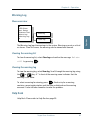
The display contrast of the two handsets can be adjusted. To change the
contrast level, select the Contrast menu and adjust the value with
or
. The contrast can be adjusted between 1 and 8. Default value is 4.
Super User functions
69
Chapter 4: Operation
Ring setup
4.3.5
Press to Adjust
Ring Setup
Key Beep
Set UTC Time
Set UTC Date
Ring Volume
4.====
Ring Volume
Ring Cadence
Ring Cadence
1.=
Press to Adjust
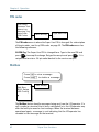
Ring setup gives the possibility to change the ringing tone and the handset
volume. Adjustable values are:
•
Ring Volume: Off | 1 | 2 | 3 | 4, default is 4.
•
Ring Cadence: 1 | 2 | 3 | 4 | 5 | 6 | 7| 8, default is 1.
Both settings are adjusted with
or
.
Key Beep
4.3.6
Ring Setup
Key Beep
Set UTC Time
Set UTC Date
Key beep
Off
Press to Adjust
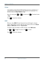
Key Beep, the sound that is heard when a key is pressed, can be set to Off, 1, 2,
3 or 4. The setting is adjusted with
70
or
Super User functions
. Key Beep is default off.
Ring Setup
Key Beep
Set UTC Time
Set UTC Date
Disclose Pos
Edit time
17:29
4.3.7
The current UTC time can be viewed and modified. The time is displayed in 24
hour format {hh:mm}. Enter a new time and press OK to update or Exit to
cancel. If the clock is set to a non-UTC time a clock error message will appear
after a while. By pressing *
, the GPS time is automatically transferred. The
clock error message can be cleared by
the message will be shown again.
Exit
,but only for 24 hours after which
Set UTC Date
4.3.8
Ring Setup
Key Beep
Set UTC Time
Set UTC Date
Disclose Pos
Edit Date
2005-05-23
The current UTC date can be viewed and modified. The date is displayed in the
format {yyyy:mm:dd}. Enter a new date and press
cancel. By pressing *
OK
to update or
Exit
to
, the GPS date is automatically transferred.
Super User functions
71
Operation
Set UTC Time
4444
Chapter 4: Operation
Chapter 4: Operation
Disclose Pos.
Disclose Pos
GPS Source
Allowed Dial
Ph.BookDial
Auto Prefix
4.3.9
*Reveal Pos
Dont Reveal
Press to Scroll
Press to select
It is possible to disable the automatic reporting of position, from the GPS
system. This menu gives the option to change this. Select Reveal Pos or Don't
reveal with the
or
keys. Select the function with the OK key.
Current status is marked with an *. The default setting is Reveal Pos.
Note
Disabling automatic reporting of position means that the terminal
will report spot beam ID instead.
Note
When a user initiates a maritime distress priority call, the position is
reported regardless of the status of the automatic reporting.
GPS Source
Disclose Pos
GPS Source
Allowed Dial
Ph.BookDial
Auto Prefix
•
72
4.3.10
*Internal
External
Press to Scroll
Press to select
If you are using the built-in GPS receiver in the TT-3008C or TT-3008F
antenna, select Internal.
Super User functions
If you are using an external GPS source as backup, select External and
connect the GPS source to the NMEA input on the BDU. Note that the
system will still use the internal GPS source as first choice when possible.
Allowed Dial
Disclose Pos
GPS Surce
Allowed Dial
Ph.BookDial
Auto Prefix
4.3.11
Press to insert mask
Press to delete mask
Operation
•
4444
Chapter 4: Operation
List empty
Allowed Dial is a function that allows the Super User to specify a phone
number mask to restrict outgoing calls.
A phone number matches a dial mask, if the number contains at least as many
digits as the mask and when the digits in the mask match the corresponding
digits in the phone number, starting from the first digit.
C
Press
to insert a mask and
to delete a mask.
Examples:
Mask: 00453955
Valid number: 004539558800
Valid number: 004539558888
Invalid number: 39558800
Invalid number: 004539
The terminal can contain up to 99 entries and each entry can be 22 digits long.
Note
The phone number you enter in the dialer for making an MPDS
connection is a dummy number that is not used. Therefore the
“Allowed Dial” list has no effect on MPDS connecting.
Super User functions
73
Chapter 4: Operation
Ph.Book Dial
4.3.12
Disclose Pos
GPS source
Allowed Dial
Ph.BookDial
Auto Prefix
Press to Scroll
Press to select
*Disabled
Enabled
When this function is enabled, Normal User will only be able to make calls
using the phone book or the Help desk from a SAILOR handset.
Use
select.
or
to scroll between ‘Enabled’ or ‘Disabled’ and press
OK
to
The function is by default disabled.
Auto Prefix
4.3.13
Disclose Pos
GPS Source
Allowed Dial
Ph.BookDial
Auto Prefix
Press to insert prefix
Press to delete prefix
Prefix no.
0045
A prefix, e.g. 0045 for Denmark, can automatically be added to any dialed
number. The prefix is not added to numbers dialed from the phone book. One
prefix number with up to 22 characters can be defined. By default no Auto
Prefix number is specified.
Press
74
C
to insert a prefix and
Super User functions
to delete the prefix.
MiniM Voice
Speech
3.1 kHz Audio
64 kbit/s
56 kbit/s
MPDS
9600 Fax
2x64 kbit/s
2x56 kbit/s
BarServicIn
BarServicOut
LED Dimm
Ant. Setup
4.3.14
Barred
*Not barred
Press to Scroll
Press to select
Operation
BarServiceIn
4444
Chapter 4: Operation
All incoming calls on a specific service can be barred. Scroll through the
services with
or
. Select the service with
be set to Barred or Not barred with
or
OK
and
. The service can then
OK
.
Please note that the 2x64 kbit/s and 2x56 kbit/s services are only visible if
128 kbit/s is enabled.
Default setting is “Not barred” for all services.
Super User functions
75
Chapter 4: Operation
BarServiceOut
4.3.15
BarServicIn
BarServicOut
LED Dimm
Ant. Setup
Barred
*Not barred
MiniM Voice
Speech
3.1 kHz Audio
64 kbit/s
56 kbit/s
MPDS
9600 Fax
2x64 kbit/s
2x56 kbit/s
Press to Scroll
Press to select
All outgoing calls on a specific service can be barred. Scroll through the
services with
or
. Select the service with
be set to Barred or Not barred with
or
OK
and
. The service can then
OK
.
Please note that the 2x64 kbit/s and 2x56 kbit/s services are only visible if 128
kbit/s is enabled.
Default setting is “Not barred” for all services.
LED Dimm
BarServicIn
BarServicOut
LED Dimm
Ant. Setup
DistressTest
4.3.16
Press to Scroll
Press to select
*Bright
Dimm
Off
The brightness of the 4 LEDs on the two handsets can be adjusted. To change
the brightness level, select the LED Dimm menu and adjust the value with
76
Super User functions
4444
Chapter 4: Operation
or
. The brightness can be adjusted to Bright, Dimm and Off.
Default value is Bright.
Menu overview
Ant.Setup
Alarm Log
Warning Log
Reset ACU
Set time out
Num. Skyscan
Mount Pos.
Upload FEU
Auto Upload
4.3.17
Operation
Antenna Setup
Set Time Out
130
Reset ACU
This function will reset the ACU in the antenna. The DC power running in the
antenna cable will be turned off for a few seconds, causing the ACU to restart.
This can be useful if the antenna control freezes or locks up.
Set time out
This function sets the number of seconds the system waits without a satellite
signal before it assumes the tracking is lost. Valid range is 1 to 300 seconds.
Default is 130 seconds. Confirm changes by pressing
OK
.
Num. Skyscan
This function enables the user to define the number of sky scans. Valid range
is 1 to 10 scans. Default is 1 scan. Confirm changes by pressing
Super User functions
OK
.
77
Chapter 4: Operation
Mount Pos.
Because of the built-in GPS, the antenna is capable of finding the satellite
within a few seconds. However, a heading of the ship is also needed. Because
the GPS does not supply the antenna with this information, you must enter a
relative angle of the antenna compared to the ships bow. Valid angles are
0(REAR), 90(PORT), 180(BOW), and 270(STARBOARD) deg, positive in a
clockwise direction. Default angle is 0 deg. Confirm changes by pressing
OK
.
Upload FEU
If a new FEU (Part of the antenna) is installed, this command will upload
software to the FEU, thereby pairing the software in the BDU and FEU. If the
FEU software version in the antenna is different from the version that is stored
in the BDU, you will get a warning. You may then use the “Upload FEU”
command to remove this difference.
Auto Upload
When Auto Upload is enabled, the terminal will automatically check the
antenna software version at startup, and upload the correct version if
necessary. The default setting is “Enabled”.
78
Super User functions
DistressTest
4.3.18
The Distress Test functionality is available on Fleet77 systems only.
Ant.Setup
Distress Test
Alarm Log
Warning Log
Help Desk
Press to Scroll
Press to select
Enable
Disable
A Distress Test is made to test the Distress call system. When the RCC receives
the call, a flag in the message is set, so that the RCC can identify the call as a
test call. Follow this Distress Test procedure:
1. Enter the DistressTest menu and use
or
and OK to enable
distress test. The display on the handset will show ‘Distress Test Enabled’
and the Distress Test LED will start flashing.
2. The Distress test mode remains active in 30 seconds, after which it
automatically disables the test again. While the distress test is enabled,
press the Distress button on the cradle for 5 seconds or until the light on
the button stops flashing and the buzzer stops beeping.
3. All ongoing calls will be preempted after 15 seconds.
4. A list of distress LESs is presented in the handset display. Use
or
and OK to select a LES. If a LES is not selected within 15 seconds, the
pre-configured LES will be selected instead.
5. The handset display will now go from ‘Distress calling’ to ‘Distress
connected’ as the call progresses. ‘Distress connected’ also means that the
test was a success.
or wait 120 seconds, after which the call
6. To abort the test call press
will automatically be disconnected.
Super User functions
79
Operation
Note
4444
Chapter 4: Operation
Chapter 4: Operation
Alarm log
4.3.19
Menu overview
LED Dimm
Ant. Setup
Distress Test
Alarm Log
Warning Log
View log
*NSR
*FEU
.
.
Clear log
Audio Alarm
On
Off
NSR
Corrupt
-----------Time
17:42
-----------Date
11-Feb-02
The Alarm Log, logs all the alarms in the system. From this menu, the alarms
can be viewed and cleared. The alarm log can contain up to 20 entries. When
the log is full, the oldest alarms are deleted.
Clearing the alarm log
To clear the alarm list, select Clear log and confirm the message Delete
all? by pressing
OK
.
Viewing the alarm log
To view the alarm log, select View log. Scroll through the alarm list, using the
or
keys. A * in front of the alarm indicates that it is still active.
To select an alarm for viewing, press OK . Each entry for an alarm contains
an alarm description and the time and date when the alarm occurred. It also
includes remedies to solve the problem. See List of Error messages on
page 135 for a list of alarms.
Audio alarm
You may get an audio alarm when an alarm is added to the alarm log. This
may be turned on and off by entering the Audio Alarm menu.
80
Super User functions
Menu overview
LED Dimm
Ant. Setup
Distress Test
Alarm Log
Warning Log
View log
4.3.20
Clear log
The Warning Log logs the warnings in the system. Warnings are not as critical
as alarms. From this menu, the warnings can be viewed and cleared.
Clearing the warning list
To clear the warning list, select Clear log and confirm the message Delete
all? by pressing
OK
.
Viewing the warning log
To view the warning log, select View log. Scroll through the warning log using
the
or
key. A * in front of the warning name indicates that the
warning is still active.
To select a warning for viewing, press OK . Each entry for a warning
contains a warning description and the time and date when the warning
occurred. It also includes remedies to solve the problem.
Help Desk
4.3.21
Help Desk. Please refer to Help Desk on page 55.
Super User functions
81
Operation
Warning Log
4444
Chapter 4: Operation
Chapter 4: Operation
PIN codes
4.3.22
Ant.Setup
Distress Test
Alarm Log
Warning Log
Help Desk
PIN Codes
SU-PIN Chg
Type New PIN
_
The PIN codes menu is where the Super User PIN is changed. For a description
of the pin codes, see Use of PIN codes. on page 39. The PIN codes menu has
the following submenu.
SU-PIN Chg: The Super User PIN is changed here. Type in the new PIN and
press OK to accept the change. Retype the new pin and press OK . It is
not possible to enter a SU-pin code identical to the service user pin!
Mailbox
4.3.23
Press to view message
Press to delete a message
Mail Box
RJ11 Setup
LES Config
List Empty
The Mailbox feature handles messages being sent from the LES operator. If a
call is made to a terminal that is busy, switched off, etc. the LES operator may
offer the facility to record a short message. When the terminal becomes
operational again, a message is sent indicating that the LES operator has
recorded a short message for the terminal.
82
Super User functions
4444
Chapter 4: Operation
The symbol in the handset display indicates the presence of such
messages.
•
LES Access Code
•
Service type (voice, fax, data).
The following operations are possible:
•
View entries
•
Delete entries.
To View an entry, select the message and press
OK
Operation
Each message can be seen in the Mailbox menu and contains the following
information:
.
To delete an entry, select the message and press
.
RJ11 Setup
4.3.24
Overview
Press
to Scroll
Press to select
Mail Box
RJ11 Setup
LES Config
Volume
PABX
*High
Medium
Low
RJ11 #1-3
Normal mode
PABX mode
The RJ11 Setup menu contains the two submenus Volume and PABX. Use
or
and
OK
to select among them.
Super User functions
83
Chapter 4: Operation
Volume
2-wire phones connected to the RJ11 interfaces may vary in sensitivity. As a
consequence the output volume from the interfaces can be adjusted. The
volume can be set to High, Medium or Low.
Adjust the setting with
is High.
Press
Exit
or
and select with
OK
. The default value
to leave the submenus.
PABX
When you select PABX (Private Automatic Branch eXchange) a submenu
appears where RJ11 #1-3 can be selected. Each of these can be set in Normal
mode and PABX mode (default is Normal mode).
If a PABX is to be connected to an RJ11 connector, select PABX mode.
Use
Press
84
or
Exit
to toggle the values and
OK
to leave the submenus.
Super User functions
to select.
Overview
Mailbox
RJ11 Setup
LES Config
Note
Default LES
PreferredLES
Reset LES
Distress LES
*W-Atlantic
E-Atlantic
Pacific
Indian
Spare 1
Spare 2
Spare 3
Spare 4
4.3.25
001:
002:
004:
005:
006:
007:
008:
009:
.
.
.
.
Comsat
BT
Telenor
OTE
Operation
LES Configuration
4444
Chapter 4: Operation
FRAC
ST12
The Distress LES functionality is available on Fleet77 systems only.
This menu is used to select a list of LES operators. It contains the following
submenus:
•
Default LES
•
PreferredLES
•
Reset LES
•
Distress LES
Default LES
The Default LES list contains a list of the LES operators that may be selected as
gateway to the terrestrial network. The last used LES will be marked with *
and this LES will also be the first LES tried next time the terminal is logged on.
If there is no LES list selected under Allowed or Preferred LES, the Default LES
list will contain the LES list from the satellite bulletin board, meaning all
Super User functions
85
Chapter 4: Operation
available LESs in the selected Ocean region. Use
select an Ocean region and then a LES.
or
and
OK
to
To edit the LES names in the Default LES list, select the name and press
to start editing the selected name.
To clear the name, press
.
An Allowed LES list can be selected under the Service User menu. If an
Allowed LES list exists, only the LESs in this list can be selected under Default
and Preferred LES. An Allowed LES list contains all available LES operators in
the selected ocean region. The operators marked with * can be used as
Default LES operators and thus appear in the Default LES list above. If all LES
operators are allowed and can be used there are no markings.
Preferred LES
As there are many operators, you can use PreferredLES to make selections
easier. The Preferred LES list can be used to indicate in which order LES
operators should appear on the Default LES list.
C for each LES intended to be on the list, in the order they
Press
should appear in the Default LES list.
A prompt for a TNID will appear in the handset display. This value is usually 0,
but in some countries with more than one terrestrial network, the TNID can
have another value. To accept the default TNID, press
again to update the preferred LES list.
To remove a LES from the list, press
list.
OK
and then
. Press
OK
to update the
Reset LES
The Reset LES command resets all the LES names to default names.
86
Super User functions
OK
Distress LES
4444
Chapter 4: Operation
The Distress LES list contains a list of the LES operators which may be selected
when making a Distress Priority Call. Use
Ocean region and then a LES.
Note
or
and
OK
to select an
Additional Features
4.3.26
Mail Box
RJ11 Setup
LES Config
Add. Features
STU Setup
128K Setup
STU PIN
_
STU
Disabled
128 K PIN
_
128K Service
Disabled
The Additional Features menu contains two submenus STU Setup (Secure
Telephone Unit) and 128K Setup. To enable the STU or 128K services a PIN
code must be entered. The PIN code can be retrieved from your distributor.
Use
or
and
OK
to choose STU Setup or 128K Setup.
If the PIN code is successfully entered you can enable or disable the service.
Use
Press
or
Exit
to toggle and
OK
to change.
to leave the submenu.
Super User functions
87
Operation
If a Distress LES is not defined for each Ocean Region, an alarm will
appear and the entry ‘Distress LES is not selected in all Ocean
Regions’ will be added to the alarm log.
Chapter 4: Operation
Data Limits
4.3.27
Overview
RJ11 Setup
LES Config
Add. Features
Data Limits
Limit OFF
000000 Kb
MPDS
ISDN
Limit OFF
00:00 hh:mm
The Data Limits menu enables the user to enter an upper limit for the use of
each high speed connection. This feature is an effective way of preventing that
a user by mistake forgets to close a connection.
The Data Limits menu contains two submenus MPDS and ISDN.
Use
or
and
OK
to select among them.
MPDS
The MPDS submenu contains two parameters: Limit and a value for the
maximum allowed amount of kilobytes that can be transferred in each call.
Limit can be either ON or OFF. If set to ON the MPDS connection will
automatically be closed down if the transferred amount of data exceeds the
entered maximum value. If set to OFF, there will be no limits for the amount of
data that can be transferred.
Use
or
to select Limit and
To enter a maximum limit press
enter a value and press
OK
OK
OK
to manipulate.
again. Then use the numeric keys to
to save. Press
Exit
to leave the submenu.
ISDN
The ISDN submenu contains two parameters Limit and a maximum duration
for each call. Limit can be either ON or OFF. If set to ON the call will
88
Super User functions
4444
Chapter 4: Operation
automatically be closed down if the call has lasted longer than the entered
maximum duration. If set to OFF, there will be no boundaries on the call
duration.
or
to select Limit and
OK
To enter a maximum call duration press
to manipulate.
OK
again. Then use the numeric
keys to enter the duration in hours and minutes and press
Exit
OK
to save. Press
to leave the submenu.
Call Waiting Notification
4.3.28
Overview
Support
Add.Features
Data Limits
Call Waiting
Limit Calls
Disabled
Enabled
Dial Spec.
Yes / No
Handset #1
Handset #2
Notification
Ring Tone
Notification
Ring Tone
RJ11
Pend. Time
Caller #1-5
Ring Tone 1-8
RJ11 #1-3
Ring Type 1-8
Pend. Time
0030
Caller # No
Number
Ring Tones
Handset
RJ11
The Call Waiting menu contains a number of submenus.
Use
or
and
OK
to select among the submenus.
Super User functions
89
Operation
Use
Chapter 4: Operation
Press OK to save the changes and press Exit to leave a menu. Please refer
to Call waiting on page 45 for general information about the Call Waiting
Notification.
Support
The Support menu is used for enabling or disabling the Call Waiting
Notification service. A third option Dial Spec. makes it possible to control the
Support setting using the AT shell command1. Choose the settings by pressing
OK
and press
Exit
to leave the menu.
Limit Calls
The user may not want all calls to interrupt the MPDS sessions. It is possible to
enter up to five phone numbers that are allowed to interrupt the MPDS
sessions while all others will be rejected. If Limit Calls is set to Enabled only
the five phone numbers are allowed to interrupt. If Limit Calls is set to
Disabled all calls are allowed to interrupt. The third option Dial Spec. makes it
possible to control the Limit Calls setting using the AT command2. Please note
that the Limit Calls service is not supported by the LES at present time.
However, it will most likely be available in near future. Choose the settings by
pressing
OK
and press
Exit
to leave the menu.
1.
If Dial Spec. is chosen, support of Call Waiting Notification can be controlled
using the AT shell command +WCWNS=<value> during the MPDS call
setup. Possible values for the AT shell command are: 0 = DISABLED, 1 =
ENABLED, 2 = AUTOMATIC.
2. If Dial Spec. is chosen the Limit Calls setting can be controlled using the AT
command +WCWNR=<value> during the MPDS call setup. Possible values
are: 0 = DISABLED, 1 = ENABLED.
90
Super User functions
Handset #1 and Handset #2
4444
Chapter 4: Operation
The Handset menus each contain two sub items: Notification and Ring Tone.
Notification can be either Yes or No and it controls whether or not the 4-Wire
Handset should be used for Call Waiting Notification.
Ring Tone can be used for choosing among the 8 Ring Tones. Select the
settings by pressing
OK
and press
Exit
to leave the menu.
Operation
RJ11
The RJ11 menu contains two sub items: Notification and Ring Tone.
Notification can be either Yes or No for each of the three RJ11 2-wire
connectors.
Ring Tone can be used for selecting a common 2-wire ring tone among eight
ring tones. The ring tones are described with the two symbols ‘#’ (sound) and
‘ ‘ (no sound). Select the settings by pressing
the menu.
OK
and press
Exit
to leave
Pending Time
The Pending Time is set to 30 seconds by default. The Call Waiting Notification
will continue for a number of seconds corresponding to the value of Pending
Time. If the user chooses to ignore the notification for a longer period the
incoming call will be ignored.
Enter a value and press OK to save when leaving the menu. Press
leave the menu without saving.
Exit
to
Caller #1-5
Each of these items (#1-5) can contain a phone number that is allowed to
interrupt the MPDS sessions, if this function is enabled in the menu item Limit
Calls.
Each number can be individually associated with a ring tone and with the 4Wire handset and/or a number of the RJ11 2-Wire connectors. Configuration is
done as described in the menu items Handset and RJ11.
Super User functions
91
Chapter 4: Operation
I/O Setup
4.3.29
Overview
Add.Features
Data Limits
Call Waiting
I/O Setup
I/O A
I/O B
I/O C
I/O D
Disabled
RsOffIn
RsOffOut
TxOffIn
TxOffOut
ActiveHigh
ActiveLow
TxActiveOut
ExtRingOut
Each input/output pin can be configured to one of these functions:
As input types: TxOffIn, RSOffIn
As output types: TxOffOut, RSOffOut, TxActiveOut, ExtRingOut
92
TxOffIn:
RSOffIn:
Input activates TxOff functionality.
Input activates Radio Silence functionality.
TxOffOut:
RSOffOut:
Output indicates that TxOff is active.
Output indicates that Radio Silence is active.
TxActiveOut:
Output indicates that Transmit is active.
ExtRingOut:
Output indicates that a call is ringing at an interface
routed to the External Ringer function.
Super User functions
4444
Chapter 4: Operation
Each input or output pin can be configured as either active high or low.
TxOff (Transmit Off):
When this function is active the terminal will stop all transmission from the
antenna by terminating the call as it is normally done. Distress alarms from
ship or from land will be allowed.
ExtRing (External Ringer):
Calls to Handset #1, Handset #2, RJ11 #1, RJ11 #2 and RJ11 #3 can be routed to
an external ringer connected to an I/O pin with the External Ringer function.
The output signal for the external ringer is activated when an incoming call to
the routed interface is received (ringing). See Routing on page 66.
The above functions can only be activated by the discrete I/O pins. The pins
have to be configured from the Super User menu, which can only be accessed
by entering a password.
Super User functions
93
Operation
RS (Radio Silence):
This function has higher priority than the Transmit-Off function. If this function
is active any transmission from the antenna will be blocked. Even distress calls
in both directions will be prohibited.
Chapter 4: Operation
94
Super User functions
Chapter 5
PC programs
5
System set-up using FleetCP
5.1
Overview
5.1.1
System set-up can be managed from a PC program called FleetCP, instead of
from the handset. FleetCP can be installed from the enclosed CD-ROM. The
following pages contain a short introduction to FleetCP. The picture below
shows the initial screen, when the program is started.
Connect the BDU to a PC using a standard RS-232 connection.
When connected, The FLEETCP will automatically download the information
from the fleet to the PC. It is also possible to click the red R button on the top
toolbar to read the current configuration from the terminal. Click the red W
button to write any changes to the terminal.
95
Chapter 5: PC programs
Select the functions by clicking in the left menu window. The menu window is
divided into the following groups: Phonebook, Help Desk, Satellite setup,
Phone Setup, Antenna Setup, General Status, Alarm Status, Call Log, Antenna
Alignment and Terminal Window.
The Map
5.1.2
Clicking the map will show the Azimuth and Elevation to the satellites
reachable in that area. See picture below.
The status bar in the lower part of the window shows longitude and latitude as
the cursor is moved around the screen.
96
System set-up using FleetCP
Chapter 5: PC programs
5555
Pin codes
5.1.3
When a correct PIN is entered, the lock icon will become unlocked and turn
green. At the same time a new logout button will appear next to the PIN code
buttons. Click this button to reset the status of all PIN codes.
If a change to the configuration is made without entering a PIN code first, a
popup asking for the PIN will appear when the Write button is pressed. See
below.
To read more about PIN codes see Use of PIN codes. on page 39.
System set-up using FleetCP
97
PC programs
The right side of the status bar shows the status of the PIN codes. If no PIN
codes are entered, all lock icons will be red and locked. Click the appropriate
button to enter or change a PIN code. See the picture below.
Chapter 5: PC programs
Phonebook
5.1.4
To enter new Phonebook entries, select Phonebook and right-click in the
phone book area. Entries here can be modified or deleted in the same way.
See the picture below. For further information, see Phonebook on page 50.
Inserting, editing and deleting entries in the Helpdesk works in a similar way.
See the Installation Manual for further information.
98
System set-up using FleetCP
Chapter 5: PC programs
5555
Satellite Setup
5.1.5
To enter the Satellite Setup window, select Satellite Setup in the left menu and
select the ocean region you want to set up.
PC programs
Satellite Setup offers an easy way of setting up Allowed, Preferred and default
LES. LES operators are dragged and dropped between the three tables. See the
picture below.
Read more about LES configuration in LES Configuration on page 85.
System set-up using FleetCP
99
Chapter 5: PC programs
Phone Setup
5.1.6
Routing
To route calls, select Phone Setup > Routing from the left menu and use the
table.
Click in the cell that corresponds to the service/interface that is to be changed.
Click the * (incoming) or # (outgoing) button in the lower part of the screen to
define it as an incoming or outgoing call. Note that the External Ringer can
only be an output.
To add an IMN, click the New IMN/ID button. See the picture below.
100
System set-up using FleetCP
Chapter 5: PC programs
5555
See Routing on page 66 and IMN Config in the Installation manual for a
detailed explanation about routing, IMN and IDs.
Setting up time and date
To correct the time/date or the language (future option), select Phone Setup >
MMI Setup.
PC programs
Click the Use PC time button to import the time and date from the PC clock. If
the clock is set to a non-UTC time a clock error message will appear on the 4W handset on the BDU after a while. Click OK.
System set-up using FleetCP
101
Chapter 5: PC programs
Barring services
In the Security window call restrictions can be enabled or disabled and an
Auto prefix inserted.
Select Phone Setup > Security to enter the Security window.
See the sections Allowed Dial on page 73, BarServiceIn on page 75 and
BarServiceOut on page 76 for more details.
102
System set-up using FleetCP
Chapter 5: PC programs
5555
Setting up the handsets
In the Cradle/Handset window it is possible to setup ring type, ring volume,
LED brightness and display contrast.
PC programs
Select Phone Setup > Cradle/Handset #1 or #2 to enter the Cradle/Handset
window.
Likewise, settings for other interfaces are available under the submenus RS232, LAN and I/O interface.
System set-up using FleetCP
103
Chapter 5: PC programs
Antenna
5.1.7
Select Antenna Setup from the left menu to change Long term failure timeout,
number of allowed sky scans and the antenna’s mount position relative to the
ship’s bow. See Antenna Setup on page 77 for details.
Select the GPS source you are using.
•
If you are not using a backup GPS source, but only the built-in GPS receiver
in the TT-3008C or TT-3008F antenna, select Internal.
•
If you are using an external GPS source as backup, select External and
connect the GPS source to the NMEA input on the BDU. Note that the
system will still use the internal GPS source as first choice when possible.
The antenna can be rebooted by clicking the Reset ACU button.
Terminal window
5.1.8
The terminal window makes it possible to run AT commands in the same way
as the Windows program HyperTerminal.
Select Fleet Tools > Terminal Window from the left menu to access the
terminal window.
104
System set-up using FleetCP
Chapter 5: PC programs
Setting up MPDS over RS-232
MPDS hardware connection
5555
Setting up data equipment
5.2
5.2.1
PC programs
The illustration below shows typical hardware setup for an MPDS data
connection.
For an MPDS session, connect an RS-232 cable between the COM port of the
computer and the COM ports on the Fleet system. The COM port on the Fleet
system is marked X10.
This setup procedure is intended for PCs running a MS-Windows operating
system.
The PC communicates with the BDU as if it were a modem. Connect the BDU to
a COM port via a standard RS-232 cable.
Configuring the TT-3084A, TT-3084B & TT-3086A
The BDU has to be configured for the right ocean region and LES operator that
provides the MPDS service. This is done using the handset user interface.
Setting up data equipment
105
Chapter 5: PC programs
The RS-232 configuration of the BDU should be (using the handset user
interface, see Data setup on page 69):
Baud rate: 115200 baud
Flow control: Hardware
Setting up your PC
This section describes in general terms how to set up an MS-Windows based
PC, covering Windows 95, 98, 2000 and NT. The screen dumps below are from
Windows 98. For a detailed description with more screen dumps of the
installations, you are referred to the Application Note “Configuring SAILOR
Fleet77 for MPDS” on your MES Software distribution disk or at our web site
www.thrane.com.
Step 1: Install a standard modem
1. From the Control Panel select Modems and add a Standard modem. Do not
let Windows detect the modem, but manually select a standard 33600 bps
Modem.
106
Setting up data equipment
Chapter 5: PC programs
5555
2. Select the appropriate COM port (i.e. the COM port that is connected to the
terminal.
3. Set maximum speed to 115200.
PC programs
4. Set Data bits = 8, Parity = None and Stop bits = 1.
Setting up data equipment
107
Chapter 5: PC programs
5. Important: Enter Advanced settings and type the initialization command
AT+MPDS in the Extra settings field.
AT+MPDS
This string is transferred to the terminal when setting up a connection.
If the MPDS connection is to use another LES than the one already
selected, use the initialization command = AT+MPDS;+WLES=XXX, where
XXX is the LES number.+WLES=XXX is only needed if MPDS LES is different
from default LES.
6. If the terminal is to stay in MPDS mode with no activity for longer periods
of time, the automatic “disconnect when idle” setting in Windows must be
disabled. Refer to your Windows manual on how to do this.
108
Setting up data equipment
Chapter 5: PC programs
5555
Step 2: Create a Dial-up connection
1. Open Dial-up Networking from My computer and click Make new
connection.
2. Select the standard modem defined during step 1 as the dial up device.
3. Enter a dummy telephone number (the number is not used but has to be
defined – write e.g. “1234” as the phone number). We recommend using a
4-digit number
PC programs
4. Give the connection a recognizable name e.g. MPDS connection, and click
Next >.
Setting up data equipment
109
Chapter 5: PC programs
5. Include TCP/IP as allowed network protocol and use default TCP/IP settings
(Server assigned IP address, Server assigned name server addresses etc.).
6. Click OK.
110
Setting up data equipment
Chapter 5: PC programs
5555
An MPDS connection can be started automatically by an application like
Internet Explorer or Outlook Express. The connection can also be established
manually as follows:
1. In Windows, open Dial-Up networking and double click the appropriate
icon.
PC programs
2. Enter username and password if necessary and click Connect.
Wait for the connection to be completed, indicated by a Dial-up
Networking icon in the task bar tray.
Disconnect by right-clicking the tray icon and choosing Disconnect.
Setting up data equipment
111
Chapter 5: PC programs
Setting up ISDN
5.2.2
ISDN hardware connection
The ISDN connection is made by connecting an ISDN modem to the computer
via an RS-232 cable. The modem is connected to the Fleet system via an ISDN
cable. The appropriate modem driver must be installed on the computer. See
the manufacturers installations guide for details on how to do this.
The terminal can be connected to ISDN equipment via an ISDN cable. The
equipment can be video phones, audio recorders, STE phones, modems, etc.
The correct routing has to be configured via the handset. See Routing on
page 66 on how to route the ISDN interface.
The setup procedure below shows how to setup an Internet connection via
ISDN.
Connect an ISDN modem to the ISDN interface. Connect the modem to a PC via
a standard RS-232 cable or a USB cable if the modem supports this interface.
Setting up your PC
Follow the modem manufacturers installation instructions for the appropriate
operating system. For this example a Lasat Unique 1280i ISDN modem was
installed under Windows 98.
112
Setting up data equipment
Chapter 5: PC programs
5555
Step 1: Install a modem
1. From the Control Panel select Modems and add a modem.
PC programs
2. Let Windows detect the modem automatically.
Setting up data equipment
113
Chapter 5: PC programs
114
Setting up data equipment
Chapter 5: PC programs
5555
Step 2: Create a Dial-up connection
1. Open Dial-up Networking from My computer. Click Make new connection.
PC programs
2. Select the Lasat modem defined during step 1 as the dial up device.
3. Click Next.
Setting up data equipment
115
Chapter 5: PC programs
4. Enter the telephone number to the Internet Service Provider. Remember
country code and area code if necessary and click Next >.
5. Give the connection a recognizable name e.g. ISDN connection, and click
Next >.
Include TCP/IP as allowed network protocol and click TCP/IP settings.
116
Setting up data equipment
Chapter 5: PC programs
5555
PC programs
6. Use TCP/IP settings (Server assigned IP address, Server assigned name
server addresses etc.) as recommended by the ISP.
After this, a connection can be started automatically by an application like
Internet Explorer or Outlook Express. The connection can also be established
manually. In Windows, open Dial-Up networking and double click the
appropriate icon. Enter username and password if necessary. Click Connect.
Wait for the connection to be completed, indicated by a Dial-up Networking
icon in the task bar tray.
The connection can be disconnected by right clicking the tray icon and
choosing Disconnect.
Setting up data equipment
117
Chapter 5: PC programs
Setting up 64 kbit/s UDI using USB
Introduction
The USB interface can be used for the 64 kbit/s UDI service from a connected
PC with a Fleet55/77 driver properly installed.
Setting up your PC
This setup procedure is intended for PCs running an MS-Windows operating
system and the screen shots are from a Windows 2000 installation. This
section is divided into two steps: Driver installation and setup of a Dial-up
connection.
Prerequisites
Before connecting the Fleet55/77, insert the Fleet CD-ROM and copy the
directory named drivers to your PC, i.e. to C:\Program Files\Thrane\.
118
Setting up data equipment
5.2.3
Chapter 5: PC programs
5555
Step 1: Install the USB Driver
1. Connect the Fleet BDU to you PC using a standard USB cable. A Found New
Hardware window will appear shortly after.
PC programs
2. After a moment the Welcome to the Found New Hardware Wizard window
appears.
Setting up data equipment
119
Chapter 5: PC programs
3. Click Next > and the Install Hardware Device Drivers window appears.
Select Display a list and click Next >.
4. Click Next > and the Hardware Type window appears. Select Modems and
click Next >.
120
Setting up data equipment
Chapter 5: PC programs
5555
PC programs
5. The Install New Modem window appears. Click Have Disk..
6. Click Browse and choose the directory where you placed the drivers. Then
click OK.
Setting up data equipment
121
Chapter 5: PC programs
7. When the next screen appears click Next >.
8. Click Next >.
122
Setting up data equipment
Chapter 5: PC programs
PC programs
5555
9. Click Yes.
10. Click Finish to complete the driver installation.
Setting up data equipment
123
Chapter 5: PC programs
11. Now open the Control Panel and double click on Phone and Modem
Options.
124
Setting up data equipment
Chapter 5: PC programs
5555
12. Select the Modem tab and choose Properties.
PC programs
13. Select the Advanced tab and enter the initialization string AT+WS45=6 and
press OK.
Setting up data equipment
125
Chapter 5: PC programs
Step 2: Create a Dial-up connection
1. Make a new connection by selecting Start > Settings > Network and Dialup Connections > Make New Connection.
A Welcome to the Network Connecting Wizard window appears.
2. Click Next >.
126
Setting up data equipment
Chapter 5: PC programs
5555
PC programs
3. Select Dial-up to private network and click Next >.
4. Select Thrane & Thrane Fleet USB and click Next >.
Setting up data equipment
127
Chapter 5: PC programs
5. Enter the destination phone number (i.e. Internet Service Provider) and
click Next >.
6. Select For all users or Only for myself and click Next >.
7. Enter a name for the dial-up connection and click Finish.
The system will now connect using USB.
128
Setting up data equipment
Chapter 5: PC programs
5555
Setup using Ethernet/PPPoE
Overview
5.3
5.3.1
PC programs
This chapter describes the set-up and operation of data connections via
Ethernet and PPPoE using various PPPoE clients.
Windows XP with built-in PPPoE client
5.3.2
Prerequisites
The PC must have an Ethernet adapter and Windows XP installed and both
must be operational. There must be a network connection between the PC and
the Fleet system. As an example the BDU can be connected to the computer
through a switch or hub or directly using a crossover cable.
Setup using Ethernet/PPPoE
129
Chapter 5: PC programs
Setting up the connection
1. From the Start menu select Settings, then Network Connections and then
Create New Connection.
This brings up the New Connection Wizard.
2. Click Next >.
3. Select Connect to the Internet and click Next >.
4. Select Setup my connection manually and click Next >.
5. Select Connect using broadband connection requiring user name and
password and click Next >.
6. Type a name for the connection, e.g.”MPDS via PPPoE” and click Next >.
7. Select Anyone and click Next >.
8. Type a random user name and password and click Next >.
9. Select the shortcut on desktop option.
10. Click Finish.
11. Now click the new shortcut on the desktop named MPDS via PPPoE.
The SAILOR F77 system should now make the connection.
Note
130
Because of the relatively long set-up time for a data connection, the
PPPoE connection may sometimes time out.
Setup using Ethernet/PPPoE
Chapter 5: PC programs
5555
Windows 2000 WinPoET PPPoE client
PPPoE Clients
5.3.3
The data connection via Ethernet and PPPoE can be established using various
PPPoE clients.
The PPPoE client WinPoet can be obtained through your local Thrane &
Thrane distributor and works for both Macintosh and PC.
Prerequisites
PC programs
The computer must have a working Ethernet adapter. Connect the BDU to the
computer through a switch or hub or connect directly using a crossover cable.
Installation
The WinPoET program will most likely be installed from a CD.
1. Double click the Setup.exe icon to begin installation.
Setup using Ethernet/PPPoE
131
Chapter 5: PC programs
2. Click Next > and Yes to accept the license agreement.
3. Choose the installation directory and click Next > to install. The program is
now installed.
4. When installation is done, click Finish to restart the computer.
132
Setup using Ethernet/PPPoE
Chapter 5: PC programs
5555
PC programs
5. Find the shortcut on the desktop called WinPoET Broadband Connection
Manager and double-click it.
6. Enter a random user name and password and click START.
The status field tells you how far you have reached in the connection process.
After a successful authentication the status of the terminal will be Connected.
The user is now capable of using the Internet as with any traditional
connection.
Setup using Ethernet/PPPoE
133
Chapter 5: PC programs
134
Setup using Ethernet/PPPoE
Chapter 6
Troubleshooting
6
List of Error messages
6.1
Inmarsat defined alarms
6.1.1
This section describes possible Cause Codes that may be displayed in the
handset of the SAILOR Fleet77 or SAILOR Fleet55.
Please note that all Cause Codes are also described in the Inmarsat SDM
(System Definition Manual).
See also Inmarsat-M SDM Module 1 paragraphs 4.6.13 and 4.6.14.
The following four fields are used in conjunction in order to signal the cause
indication result:
Cause code 1097:
A = Coding Standard (1 bit)
e.g. 1
B = Cause Location (4 bit)
0
C = Cause Class (4 bit)
9
D = Cause Value (4 bit)
7
135
Chapter 6: Troubleshooting
The list below shows the Cause codes that may be displayed in the handset.
Cause code
136
Description
Event
0001
Data connection was released (either
by the SBS or the MES itself).
0002
MES was de-registered from the MPDS
network (either by the SBS or the MES
itself).
00F0
The MES did not get any responses on
its attempt to register with the MPDS
network.
00F1
Data connection establishment did not
succeed.
1001
Normal
MES is clearing the call as instructed
by the relevant MES terminal
equipment (i.e., normal clearing due
to MES terminal “on-hook” etc.)
1011
Called party is
busy.
MES is rejecting the call because the
specified MES terminal number is
currently busy, and MES has not been
authorized to divert calls which are
addressed to that number.
List of Error messages
Chapter 6: Troubleshooting
Event
1012
Called party is
busy
MES is clearing the fixed-originated
call because subsequent to the
acceptance of the call and the
signaling of the identity of the mobile
terminal to which the call will actually
be routed, that terminal has become
busy and hence cannot be called.
1021
No User
responded
MES is clearing the call because
appropriate “off-hook” signaling has
not been received from the addressed
MES terminal (including any
authorized diversions) within the
allowed time limit.
1081
Identified channel
does not exist
MES is rejecting the call because the
specified MES terminal number has
not been installed, and MES has not
been authorized to divert calls which
are addressed to that number.
1091
Destination out of
order
MES is rejecting the call because the
specified MES terminal number is
currently out-of-service, and MES has
not been authorized to divert calls
which are addressed to that number.
List of Error messages
137
Troubleshooting
Description
6666
Cause code
Chapter 6: Troubleshooting
Cause code
1092
138
Description
Event
Destination out of
order
MES is clearing the fixed-originated
call because subsequent to the
acceptance of the call and the
signaling of the identity of the mobile
terminal to which the call will actually
be routed, that terminal has become
out-of-service and hence cannot be
called.
1141
Call cleared, MES initiated preemption
1142
Call cleared, MES initiated preemption
1143
Preemption
1144
Reserved
1145
Preemption
MES is prematurely clearing the fixedoriginated call which is in the process
of being established, because the MES
user has initiated a call from a
terminal which is authorized to
automatically preempt an existing
fixed-originated call.
MES is prematurely clearing the
mobile-originated call which is in the
process of being established, because
the MES user has initiated a call from
a terminal which is authorized to
automatically preempt an existing
mobile-originated call.
List of Error messages
Chapter 6: Troubleshooting
Normal
Event
MES is prematurely clearing the
mobile-originated call which is in the
process of being established because
the MES user has abandoned the call
(by placing the originating terminal
“on-hook”).
11A0
LES is clearing the call because the
credit card being used is not valid (at
this LES) for calls to the country
indicated in the “service address”
information received from the MES
11D1
Inconsistency in
designated
outgoing access
information and
subscriber class.
LES is rejecting the call because the
“Service Nature” and/or “Service
Type” and/or “Channel parameter”
information received from the MES is
invalid (e.g., not currently defined in
the SDM, mutually contradictory, or
not applicable to a MES-originated
call).
11D2
Invalid number
format (address
incomplete)
LES is clearing the call because the
“service address” information received
from the MES is invalid (i.e., less than
2 digits)
11D3
Protocol error,
unspecified
LES is clearing the call because the
“service address” information received
from the MES is a 2-digit address
which is either undefined or which is
currently unavailable at this LES.
List of Error messages
139
Troubleshooting
1146
Description
6666
Cause code
Chapter 6: Troubleshooting
Cause code
Event
11D4
Protocol error.
Unspecified
LES is clearing the call because “credit
card data” information received from
the MES is invalid. [This does not
imply that the credit card itself is
invalid].
11D5
Protocol error,
unspecified
LES is clearing the call because the
“service address” information received
from the MES contains a country code
which is regarded (by this LES) as
invalid.
11D6
Inconsistency in
designated
outgoing access
information and
subscriber class.
LES is clearing the call because the
"PID" information received from the
MES in the "scrambling vector"
message (type 8DH) is not consistent
with the PID information in the
Fixed/MES-Originated (PID) and
PID/MES Registration Tables at the
LES as it relates to this call.
11E0
LES is clearing the call because the
credit card PIN received from the MES
is not considered (at this LES) to be
valid.
11E1
LES is clearing the call because it has
been determined that an excessive
number of consecutive call attempts
with invalid credit card PINs have been
made.
1201
140
Description
Reserved
List of Error messages
Chapter 6: Troubleshooting
Reserved
1262
Event
Call cleared, MES time-out (Distress
Test exceeded 120 s)
1281
Channel type not
implemented.
MES is rejecting the call because the
MES is not equipped to provide the
specified service.
1291
Requested
circuit/channel
not available.
MES is rejecting the call because
although it is equipped to provide the
specified service, it is not currently
able to do so.
12B1
Interworking.
Unspecified.
MES is rejecting or clearing the call for
a reason which is not covered by any
of the currently defined "Cause"
events.
12C1
Call failed, MES time-out (no
scrambling vector ack).
12C2
Protocol error.
Unspecified.
MES is clearing the call because a
"credit card valid" message (type A7H)
has not been received by the MES
within the allowed time limit.
12C3
No User
responded.
MES is clearing the call because a "LES
Connect" message (type 8CH) has not
been received by the MES within the
allowed time limit.
List of Error messages
141
Troubleshooting
1261
Description
6666
Cause code
Chapter 6: Troubleshooting
Cause code
142
Description
Event
12C4
Protocol error.
Unspecified.
MES is clearing the call because the
"authentication query" ISU message
(type B4H) and/or the "authentication
query" SSU message (type B5H) have
not been received by the MES within
the allowed time limit.
12C5
Protocol error.
Unspecified.
MES is clearing the call because
expected supplementary services SU(s)
has(have) not been received by the
MES within the allowed time limit.
12C6
Protocol error.
Unspecified.
MES is clearing the call because the
“supplementary services
interrogation” ISU (type B2H), and/or
“subscriber digits” SSU (type ADH)
messages have not been received by
the MES within the allowed time limit.
12C7
Protocol error.
Unspecified.
MES is clearing the call because a
“SCPC channel release” SU (type 8AH)
has not been received by the MES, in
response to the transmission of a
“notification acknowledge” message
(type BAH) during the supplementary
services call diversion information
retrieval process, within the allowed
time limit.
List of Error messages
Chapter 6: Troubleshooting
Event
12C9
Protocol error,
unspecified.
MES is clearing the call in mobileoriginated call setup, because a
subsequent 56/64 kbit/s call request
was not received from the mobile-user
TE / calling party following
establishment of a previous 56/64
kbit/s call multiplexed onto a carrier.
12CA
Protocol error,
unspecified.
MES is clearing the call in mobileoriginated call setup, because LES
connect messages have not been
received from the LES following a
request (through Channel Alert
messages) to establish a subsequent
56/64 kbit/s call multiplexed onto a
single carrier.
12D1
Protocol error,
unspecified.
LES is rejecting the call because the
“spot-beam ID” information received
from the MES is invalid (i.e., ID is not
allocated on satellite in use).
12D2
Protocol error.
Unspecified.
LES is clearing the call because the
“Scrambling Vector” information
received from the MES is invalid
(ie,0000H, 6959H or 7FFFH).
1351
1361
MES is clearing the call because the
MES currently has insufficient free
memory in which to store the short
message.
Temporary
failure.
MES is clearing the call because the
Above-decks equipment is about to
“cable unwrap”.
List of Error messages
143
Troubleshooting
Description
6666
Cause code
Chapter 6: Troubleshooting
Cause code
Description
Event
1362
Recovery on timer
expiry.
MES is clearing the call because a
long-term interruption in reception
has occurred (the definition of a
“long-term interruption” depends
upon the service type, see Section B).
1363
Preemption.
A Secondary Functional Center of a
Multi-channel MES is clearing the call
because the Primary Functional center
has commanded the Above-decks
equipment to repoint to a different
Ocean Region.
1392
144
Call cleared, spot beam transition.
1451
No
circuit/channel
available.
LES is rejecting the call because an
appropriate terrestrial circuit is not
currently available at this specific LES.
1452
No
circuit/channel
available
LES is rejecting the call because an
appropriate channel unit and
associated terrestrial circuit are not
currently available at this LES. [This
“cause” is only utilized when there is
a permanent “one-to-one” connection
between appropriate channel units
and their terrestrial circuits].
List of Error messages
Chapter 6: Troubleshooting
Event
14C1
LES is clearing the call in mobileoriginated call setup because ISDN
Channel Alert messages (used to
establish a subsequent 56/64 kbit/s
call multiplexed onto a single carrier)
have not been received from the MES
following transmission of MES connect
messages.
1541
Call cleared, preempted at LES.
1551
LES is rejecting the call because an
appropriate satellite channel is not
currently available at this specific LES.
1552
Reserved
1581
Requested
circuit/channel
not available
LES is rejecting the call because the
requested service is not provided by
this specific LES.
1591
Temporary failure
LES is rejecting the call because the
requested service is temporarily not
available at this specific LES.
1592
15A1
LES is clearing the call because the
specified credit card type is not
currently supported by this specific
LES.
Bearer capability
not authorized
LES is rejecting the call because the
specified MES is not authorized for any
service at this specific LES.
List of Error messages
145
Troubleshooting
Description
6666
Cause code
Chapter 6: Troubleshooting
Cause code
15A2
146
Description
Event
Bearer capability
not authorized
LES is rejecting the call because the
specified MES is not authorized to use
specific requested service via this
specific LES.
15A3
LES is clearing the call because the
“credit card data” information
received from the MES has been
rejected by the credit card
authorization process.
15A4
LES is clearing the call because the
data received from the MES in the
“authentication reply” message (type
B6H) has been declared “invalid” by
the LES authentication process.
15A5
Bearer capability
not authorized
LES is rejecting the call because the
specified PID is not authorized for any
service at this specific LES.
15A6
Bearer capability
not authorized
LES is rejecting the call because the
specified PID is not authorized to use
specific requested service via this
specific LES.
15B1
Interworking.
Unspecified.
LES is rejecting or clearing the call for
a reason which is not covered by any
of the currently defined “Cause”
events.
List of Error messages
Chapter 6: Troubleshooting
Event
15C1
Protocol error,
unspecified.
LES is rejecting the call because an
appropriate “Channel Assignment”
message has not been received by the
LES within the allowed time limit.
15C2
Protocol error.
Unspecified.
LES is clearing the call because the
“service address” information has not
been received by the LES within the
allowed time limit.
15C3
Protocol error,
unspecified.
LES is clearing the call because a
“Scrambling Vector” message (type
8DH) has not been received by the LES
within the allowed time limit.
15C4
Protocol error.
Unspecified.
LES is clearing the call because
neither the “service address”
information nor a “Scrambling Vector”
message (type 8DH) has been received
by the LES within the allowed time
limit.
15C5
Protocol error.
Unspecified.
LES is clearing the call because the
complete “credit card data”
information has not been received by
the LES within the allowed time limit.
15C6
Reserved
Call failed, LES time-out (return carrier
identifier).
15C7
No answer from
user (user
alerted).
LES is clearing the call because a
“MES Connect” message (type 99H)
has not been received by the LES
within the allowed time limit.
List of Error messages
147
Troubleshooting
Description
6666
Cause code
Chapter 6: Troubleshooting
Cause code
15C8
Event
Reserved
15C9
LES is clearing the call because a
“authentication reply” message (type
B6H) has not been received by the LES
within the allowed time limit.
15CA
LES is clearing the call because a
“notification acknowledge” message
(type BAH) has not been received by
the LES within the allowed time limit.
15CB
LES is clearing the call because the
request sequence number contained
in the received “notification
acknowledge” message (type BAH) is
not valid (i.e. either not ‘0’ or not the
next value in the sequence).
15CF
LES is clearing the call because MES
connect messages have not been
received from the MES following
transmission of Channel Alert
messages or LES connect messages
used to establish a subsequent 56/64
kbit/s call multiplexed onto a single
carrier.
15D1
148
Description
Message with
unrecognized
parameter,
discarded.
LES is rejecting the call because the
“Channel Assignment” message
received from the NCS contains
inappropriate or conflicting
information.
List of Error messages
Chapter 6: Troubleshooting
Event
15D2
CES → NCS
Signaling only.
LES is clearing this MES ID and
channel number in the busy lists at
LES and NCS because a new call
to/from this MES is being set-up (and
thus any previous call to/from this
MES must have cleared).
15E1
Preemption circuit reserved
for reuse.
LES is attempting to clear an MES
which has sent an SCPC channel
release message but is found still to be
transmitting 5.12 s later.
1651
No
circuit/channel
available.
LES is rejecting the call because an
appropriate channel unit is not
currently available at this specific LES.
1661
Recovery on timer
expiry.
LES is clearing the call because of an
interruption in reception of the MES
carrier exceeding the allowed time
limit.
16C1
Reserved
16C2
Recovery on timer
expiry.
1790
LES is clearing the call because an
appropriate SCPC MES carrier has not
been received by the LES (at the
commencement of the call) within the
allowed time limit.
LES is clearing the call because of a
malfunction in the credit card validity
checking database or in the
communications links thereto.
List of Error messages
149
Troubleshooting
Description
6666
Cause code
Chapter 6: Troubleshooting
Cause code
Description
1791
1811
LES is clearing the call because of a
malfunction in the authentication
checking database or in the
communications links thereto.
Called party is
busy
NCS is rejecting the call because the
specified MES ID is in the ”MES busy”
list at the NCS.
1841
Call cleared, NCS initiated preemption
for incoming Pri 1 call.
1842
Call cleared, NCS initiated preemption
for incoming Pri 2 call.
1843
Call cleared, NCS initiated preemption
for incoming Pri 3 call.
1844
Call cleared, NCS initiated channel
preemption.
1851
150
Event
No
circuit/channel
available
NCS is rejecting the call because an
appropriate SCPC channel is not
currently available.
1855
Call rejected, preemption failed, no
channel available.
1856
Call rejected, spot beam selection
failed.
List of Error messages
Chapter 6: Troubleshooting
Event
Bearer capability
not authorized.
NCS is rejecting the call because the
specified MES ID was not found in the
“Forward and Return MES ID” crossreference table.
18B1
Interworking,
unspecified.
NCS is rejecting or clearing the call for
a reason which is not covered by any
of the currently defined “Cause”
events.
18C1
Subscriber
absent.
NCS is rejecting the call because no
message was received from the
specified MES (in reaction to a Call
Announcement message) within the
allowed time limit.
18E1
Called Party is
busy.
NCS is rejecting the call because the
specified MES ID is in the “MES busy”
list at the NCS, and is listed as being
busy with a call through the same LES
as that now requesting a “call
announcement” addressed to that
MES.
Normal
LES is clearing the call because of the
receipt of “on-hook” signalling from
the relevant terrestrial circuit (i.e.,
normal clearing).
18A3
Troubleshooting
18A1
Description
6666
Cause code
1C61
1F01
List of Error messages
151
Chapter 6: Troubleshooting
Cause code
Description
1F11
Called Party is
busy.
LES is clearing the call because the
terrestrial called party is engaged
(busy).
1F21
No User
responded.
LES is clearing the call because
appropriate “off-hook” signalling from
the terrestrial called party has not
been received by the LES within the
allowed time limit.
1F31
152
Event
LES is clearing the call in fixedoriginated call setup, because a
subsequent 56/64 kbit/s call request
was not received from the terrestrialuser TE / calling party following
establishment of a previous
56/64 kbit/s call multiplexed onto a
single carrier.
1F61
Destination out of
order.
LES is clearing the call because of the
detection of a failure in the relevant
terrestrial circuit.
1F62
Normal
The LES is clearing the call because
the terrestrial calling party or the
terrestrial network has cleared the call
before the “MES connect” message
has been received by the LES.
List of Error messages
Chapter 6: Troubleshooting
6666
Non-Inmarsat Alarms
6.1.2
The table below shows the non-Inmarsat alarms.
Alarm type
Tx-Level Not Ok
1. LO Lock Not Ok
2. LO Lock Not Ok
3. LO Lock Not Ok
Vtune Alarm
Unanswered distress call received
Troubleshooting
CPU Alarms
Alarm messages
Unanswered urgency priority call received
Distress LES not selected in all ocean regions
One or more of the selected distress LESs are not
operational
At least one selected distress LES has no distress
capability
Invalid position information received from GPS
MSR Corrupt
MIR Corrupt
MIDR Corrupt
NAR Corrupt
NSR Corrupt
SVR Corrupt
List of Error messages
153
Chapter 6: Troubleshooting
Antenna Alarms
Antenna (FEU), Wrong Type, Check Conf.
Antenna (FEU) Link Down, Check Cable
FEU Reset, Powered Down
FEU Reset, Sleep Mode
FEU Error, To Follow
FEU Status, heat alarm
FEU Status, burst alarm
FEU Status, power alarm
FEU Status, reset
FEU Version Mismatch, Try Upload
ACU Comm, Failure
ACU Reset, Powered Down
ACU Reset, Sleep Mode
ACU Error, To Follow
Kernel Error, Float pnt
Kernel Error, 80Hz tsk overrun
Kernel Error, RX2 UART tsk overrun
Kernel Error, SCI tsk overrun
Memory Error, Cont SW CRC
Memory Error, ACU Cnf Data
Memory Error, ACU Cal CRC
Memory Error, FLASH mem
Memory Error, ACU SRAM
154
List of Error messages
Chapter 6: Troubleshooting
6666
Memory Error, ACU EEPROM
Memory Error, FPGA Init
Memory Error, FPGA SW CRC
Motor Error, Azm Drive
Motor Error, Elv Drive
Motor Error, Azm Winding
Motor Error, Elv Winding
Motor Error, BSM Winding
Motor Error, FPGA cmdtmo
Pos feedback, BSM Zero Ref
Troubleshooting
Antenna Alarms
Pos feedback, Azm Encoder
Pos feedback, Elv Encoder
Pos feedback, Elv Positive End Stop
Pos feedback, Negative End Stop
Pos feedback, Azm Zero Ref
SU Error, Cal Data CRC
SU Error, Initialize
SU Error, Comm
SU Error, protocol
SU Error, Sys Info CRC
Sensor Err, Roll Incl
Sensor Err, Pitch Incl
Sensor Err, Roll Rate
List of Error messages
155
Chapter 6: Troubleshooting
Antenna Alarms
Sensor Err, Pitch Rate
Sensor Err, Yaw Rate
Ctrl Logic, ACU Matrix
Ctrl Logic, RX2 Comm
Ctrl Logic, RX2 AutoTune
Ctrl Logic, ACU resett.
Ctrl Logic, RX2 tunetmo
Ctrl Logic, RX2 dither
Ctrl Logic, RX2 PLL
RX2 Error1, EEPROM
RX2 Error1, Temperature
RX2 Error1, No Signal
RX2 Error1, Channel Out Of Range
RX2 Error1, Param Out Of Range
RX2 Error1, AutoTune
RX2 Error2, RX2 RSSI lo
RX2 Error2, RX2 RSSI hi
UNKNOWN ERR pos:
Handset Alarms
Handset COMErrora
a. This error means that the communication between handset and BDU has
stopped for some reason. It is not necessarily an error caused by the handset,
but it may be caused by errors in e.g. BDU, ADU, and/or connection cables.
156
List of Error messages
Appendix A
Menu Tree
A
Main menu
A.0.1
Map Legend
Main Menu
Phonebook
Scroll through
phone book
Menu/Submenu
Selection List
Area
None
*Automatic
W-Atlantic
E-Atlantic
Pacific
Indian
Spare 1
Spare 2
Spare 3
Spare 4
LES
Avaible LES
in the region
Mailbox
View
Helpdesk
Scroll through help
desk
Alarm log
View
Value entry
Not in Fleet 55
Status
Super User
Service User
Super User PIN
Service User PIN
157
Appendix A: Menu Tree
Status menu
Status
A.0.2
C/No
C/No
xx.x dBHz
Transceiver
Release date :
Unit type :
Serial No .:
ISN:
PCB No .:
Forward ID:
SW Ver.:
RF Block
Rx Frequency :
Freq. offset :
Acc. offset :
ACG:
Gain:
Tx level :
Lo1:
Lo2:
Lo3:
Temperature :
Power Mode :
Bulletin
Ocean Region :
Type :
Page 1 Issue:
Page 2 Issue:
Page 3 Issue:
Page 4 Issue:
Page 5 Issue:
Page 6 Issue:
Spot Beam ID :
SU CC RXed:
SU CC TXed :
Antenna
FEU
ACU
158
GPS Info
PositionInfo
Heading
Speed
UTC time
Internal
External
Handset
Handset #1
Ver.#.#.#
Cradle #1
Ver.#.#.#
Handset #2
Ver.#.#.#
Cradle #2
Ver.#.#.#
Unit Type :
Serial No .:
SW version:
Mode :
Temperature :
Cable Loss :
Reset count :
Date
Unit Type :
Serial No .:
State:
Input power :
Control ver .:
Loader ver .:
FPGA ver.:
SU ver .:
RX2 ver .:
Loader CRC :
Control CRC :
FPGA CRC:
Config CRC :
AAAA
Super User menu
A.0.3
Super User PIN
Super User
Call logs
Routing
Data setup
Logged Calls
Total Time
Total MPDS
Clear Log
Handset #1
Handset #2
RJ11 #1
RJ11 #2
RJ11 #3
ISDN
RS232/USB
Baud rate
Flow ctrl
Contrast
Ring Setup
Mini-M Voice
3.1 kHz Audio
Speech
64 kbit/s
56 kbit/s
9600 Fax
MPDS
2x56 kbit/s *)
2x64 kbit/s *)
Ext.Ringer
115200
57600
38400
19200
9600
4800
2400
1200
None
Xon/Xoff
Hardware
+++ mode
Enabled
Disabled
Result codes
Enabled
Disabled
End Data
Enabled
Disabled
1.=
2.==
3.===
4.====
5.=====
6.======
7.=======
8.========
In (*)
Out (#)
Off
1.=
2.==
3.===
4.====
Ring volume
Ring Cadence
*) Only on F77 and if the service is enabled
1.
2.
3.
4.
5.
6.
7.
8.
159
Menu Tree
Appendix A: Menu Tree
Appendix A: Menu Tree
Super User menu, continued
Off
1.=
2.==
3.===
4.====
Key Beep
Set UTC time
Edit time
Set UTC date
Edit date
Disclose Pos
Reveal Pos
Don't reveal
GPS Source
Internal
External
Allowed Dial
Setup allowed dial
Ph.Book Dial
Auto Prefix
BarServiceIn
BarServiceOut
*) Only on F77 and if the service is enabled
160
A.0.4
Enabled
Disabled
Prefix no .
MiniM Voice
Speech
3.1 kHz Audio
64 kbit/s
56 kbit/s
MPDS
9600 Fax
2x64 kbit/s *)
2x56 kbit/s *)
Barred
Not barred
MiniM Voice
Speech
3.1 kHz Audio
64 kbit/s
56 kbit/s
MPDS
9600 Fax
2x64 kbit/s *)
2x56 kbit/s *)
Barred
Not barred
AAAA
Super User menu, continued
LED Dimm
Bright
Dimm
Off
Ant.Setup
Reset ACU
Set time out
Num. SkyScan
Mount Position
Upload FEU
Auto Upload
DistressTest
Alarm log
A.0.5
Enable
Disable
View log
Clear log
Audio Alarm
Warning log
On
Off
View log
Clear log
Help Desk
PIN Codes
Scroll through
Help desk
phone numbers
Edit numbers
SU PIN Chg
Mail Box
RJ11 Setup
Volume
PABX
High
Medium
Low
RJ11 #1
RJ11 #2
RJ11 #3
Normal mode
PABX mode
161
Menu Tree
Appendix A: Menu Tree
Appendix A: Menu Tree
Super User menu, continued
LES Config
Add. Features
Default LES
PreferredLES
Reset LES
Distress LES
STU Setup
128 K Setup
Data Limits
Call Waiting
I/O Setup
A.0.6
W-Atlantic
E-Atlantic
Pacific
Indian
Spare 1
Spare 2
Spare 3
Spare 4
STU PIN
_
STU
Disabled
128 K PIN
_
128 K Service
Disabled
MPDS
Limit ON/OFF
000000 Kb
ISDN
Limit ON/OFF
00:00 hh:mm
Support
Limit Calls
Handset #1
Handset #2
RJ11
Pend. time
Caller #1
:
Caller #5
I/O A
I/O B
I/O C
I/O D
Yes
No
Notification
Ring tone
1.=
2.==
3.===
4.====
5.=====
6.======
7.=======
8.========
Disabled
RsOffIn
RsOffOut
TxOffIn
TxOffOut
TxActiveOut
ExtRingOut
162
Comsat
BT
Telenor
etc.
ActiveHigh
ActiveLow
AAAA
Service User menu
A.0.7
Service User PIN
Service User
LES Config
Default LES
PreferredLES
Allowed LES
Reset LES
Distress LES
IMN Config
MiniM voice
Speech
3.1 kHz Audio
64 kbit/s
56 kbit/s
9600 Fax
MPDS
2x56 kbit/s *
2x64 kbit/s *
PIN Codes
SeU-PIN Chg
SU PIN
SU Unblock
Dflt. Setting
Factory Dflt .
Calibration
IQ-calib
Perform IQ
calibration ?
IQ-const
Modulator
Demodulator
MO adjust
Debug
W-Atlantic
E-Atlantic
Pacific
Indian
Spare 1
Spare 2
Spare 3
Spare 4
Comsat
BT
TeleNor
etc.
Tel. number
Ok to reset ?
IAmp:
QAmp:
IOff:
QOff :
Phase:
W-Atlantic
E-Atlantic
Pacific
Indian
Best choice
Power Downs
FEU Uploads
Cable Test
Ant. Test
Sys Watchdog
Watchdog Off /On
000 Hours
*) Only on F77 and if the service is enabled
163
Menu Tree
Appendix A: Menu Tree
Appendix A: Menu Tree
164
Glossary
Glossary
B
A
ACU
Antenna Control Unit
ADU
Above Deck Unit
B
BDU
Below Deck Unit
F
FEU
Front End Unit
G
GPS
Global Positioning System
I
IMN
Inmarsat Mobile Number
IMSO
International Maritime Satellite Organisation
ISDN
Integrated Services Digital Network
ISN
Inmarsat Serial Number
ISP
Inmarsat Service Provider
L
LCD
Liquid Crystal Display
LED
Light Emitting Diode
165
Glossary
LES
Land Earth Station
M
MES
Mobile Earth Station
MMI
Man Machine Interface
MPDS
Mobile Packet Data Service
MSN
Mobile Subscriber Number
N
NCS
Network Coordination Station
NSR
Network Status Record
P
PABX
Private Automatic Branch eXchange
PIN
Personal Identification number
PSTN
Public Services Telephone Network
PUK
Personal Unblocking Key, or PIN Unblocking Key
R
RCC
Rescue Coordination Center
S
STE
Secure Telephone Equipment
STU
Secure Telephone Unit
166
T&T
Thrane & Thrane A/S
TNID
Terrestrial Network ID
Glossary
BBBB
T
Glossary
U
UDI
Unrestricted Digital Information
USB
Universal Serial Bus
167
Glossary
168
Index
Index
Numerics
128 kbit/s, 16, 47, 67, 87
2nd functions, 29
3.1 kHz audio, 4, 67
56 kbit/s, 4, 67
64 kbit/s, 4, 45, 67
A
ACU, 77, 104
additional features, 87
ADU, 8, 11
alarm, 25, 55, 135
alarm Log, 55, 80
allowed dial mask, 73
alpha-numeric keys, 31
antenna, 7, 10, 104
Area, 52, 53
AT commands, 104
Azimuth, 96
B
barring, 75, 102
Baud rate, 69, 106
BDU, 7, 10
brightness, 76, 103
bulletin board, 85
C
configuration module, 8, 11
connectors, 13
contrast, 69, 103
country code, 5
D
data flow, 69
Data Limits, 88
data setup, 69
date, 71, 101
Dial-Up networking, 109, 111, 117
discrete I/O, 13, 19
Distress button, 9, 43, 79
Distress call, 9, 43, 62
Distress cradle, 7, 43, 79
distress LES, 43, 79
Distress Test, 79
document number
this manual, i
E
electronics unit, 7, 10
Elevation, 96
e-mail, 45
Ethernet, 13
external ringer, 19
configuring discrete I/O, 92
routing, 67, 100
C
C/No, 57
call log, 64
Call Waiting notification, 45, 89
calling the terminal, 42
Cause Codes, 135
F
fax, 61
file transfer, 45
FleetCP, 95
169
Index
function keys, 26
G
geostationary, 3
GPS, 8, 11, 72, 104
H
handset, 7, 10, 13, 22, 66
Help Desk, 55, 81
I
IMN, 5, 67, 100
Inmarsat Fleet service, 3
internal calls, 63
international access codes, 42
Internet Explorer, 111, 117
IP/LAN, 45
ISDN, 13, 16, 47, 61, 66
ISN, 57
ISP, 5
M
Mailbox, 54, 82
manual
document number, i
mask, allowed dial, 73
menu, 49
microwave radiation, iii
Mini-M voice, 4
mounting position, 78, 104
MPDS, 4, 45, 105
N
Network Coordination Stations, 3
NMEA, 13, 18, 73, 104
Normal User, 39, 49
O
ocean region, 52, 86
Outlook Express, 111, 117
P
K
Key Beep, 70
keys, alphanumeric, 31
keys, function, 26
L
language, 101
LED, 76
LES, 3, 53, 85, 99
170
phone book, 50, 60, 98
PIN code, 39, 82, 87, 97
position, 72
power, 25
Power button, 35, 36, 38
PPPoE, 129, 131
preempt, 43, 79
prefix, 41, 74, 102
Priority call, 44, 62
PUK code, 40
U
radiation, iii
RCC, 43
redial, 60
Ring setup, 70, 103
ringing tone, 70
RJ11, 13, 15, 60, 61, 63, 66, 83
Routine-personal, 62
Routine-professional, 62
routing, 100
RS-232, 13, 17, 66, 69, 103, 105
Urgency call, 62
USB, 13, 66, 118
S
Safety call, 62
satellite, 3
Secure Telephone Unit, 87
Service User, 40, 49
services, 6
setup using Ethernet & PPPoE, 129
short code, 50, 60
short message, 54, 82
sky scans, 77, 104
software version, 57
Speech, 4
spot beams, 3
Status, 56
Stop button, 9
STU, 87
Super User, 40, 49
V
Index
CCCC
R
Index
volume, 70, 103
W
warning Log, 81
web browsing, 45
Windows 2000 and PPPoE, 131
Windows XP and PPPoE, 129
T
time, 71, 101
time out, 77, 104
TNID, 86
171
Index
172
TT-98-116874-I
Thrane & Thrane A/S
•
[email protected]
•
www.thrane.com