1
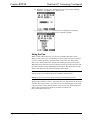
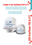
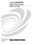
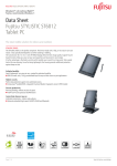
Crestron DTT-18 DualTouch™ Technology Touchpanel Operations Guide This document was prepared and written by the Technical Documentation department at: Crestron Electronics, Inc. 15 Volvo Drive Rockleigh, NJ 07647 1-888-CRESTRON All brand names, product names and trademarks are the property of their respective owners. ©2004 Crestron Electronics, Inc DualTouch™ Technology Touchpanel Crestron DTT-18 Contents DualTouch™ Technology Touchpanel: DTT-18 1 Introduction ........................................................................................................................1 Features and Functions .............................................................................................................. 1 Specifications ............................................................................................................................ 3 Physical Description .................................................................................................................. 4 Industry Compliance.................................................................................................................. 9 Setup.................................................................................................................................10 Mounting ................................................................................................................................. 10 Hardware Hookup.................................................................................................................... 11 Display Settings....................................................................................................................... 13 Using the Pen........................................................................................................................... 16 Cleaning................................................................................................................................... 17 Alternative Mounting .............................................................................................................. 17 Problem Solving ...............................................................................................................18 Troubleshooting....................................................................................................................... 18 Further Inquiries ...................................................................................................................... 19 Future Updates......................................................................................................................... 19 Return and Warranty Policies...........................................................................................20 Merchandise Returns / Repair Service..................................................................................... 20 CRESTRON Limited Warranty............................................................................................... 20 Operations Guide – DOC. 6290 Contents • i DualTouch™ Technology Touchpanel Crestron DTT-18 DualTouch™ Technology Touchpanel: DTT-18 Introduction Features and Functions The DTT-18 is an 18-inch touchpanel designed for use with the UPX-2 Universal Presentation System. The Crestron exclusive DualTouch™ Technology (patent pending) allows the DTT-18 to function both as a touchpanel and a pen-based annotation device to produce an amazingly flexible presentation solution. Crestron DualTouch Technology touchpanels employ a combination of analog resistive touch sensing for fingertip-operated touchpanel control and the exclusive Wacom® pen-based technology for precise drawing and annotation. Switching between modes is automatic and instantaneous, disabling the analog membrane whenever the pen is sensed allowing users to rest the palm of their hand naturally on the screen while drawing. Functional Summary • Provides the primary user interface for the Crestron UPX-2 Universal Presentation Processor • Displays high-resolution RGB video from the UPX-2 • 18-inch color display with 1280 x 1024 native resolution • Employs DualTouch Technology to support touchpanel control and penbased annotation as part of a complete UPX system • Includes a tabletop stand with versatile tilt and rotation adjustments NOTE: The DTT-18 can only be used with the UPX-2. Operations Guide – DOC. 6290 DualTouch™ Technology Touchpanel: DTT-18 • 1 Crestron DTT-18 DualTouch™ Technology Touchpanel DTT-18 DualTouch Technology Touchpanel and UPX-2 Universal Presentation Processor Typical Application 2 • DTT-18: DualTouch™ Technology Touchpanel Operations Guide – DOC. 6290 DualTouch™ Technology Touchpanel Crestron DTT-18 Specifications The following table provides a summary of specifications for the DTT-18. DTT-18 Specifications SPECIFICATION DETAILS Power Requirements 72 Watts (4 Amps @ 18 Volts DC) Power Supply Included Connectors Integral breakout cable Video One 29-pin DVI Male Connector, DB15HD/VGA adaptor included (connects RGB output from output port A of the UPX-2 using VGA adaptor) RS-232 One DB9 Female Connector, bi-directional port. Not used with the UPX-2. USB One USB A Female Connector for Communications connection to the UPX-2 Processor (to any of the four USB UPX-2 ports) Power One 4-pin Connector for Power Supply Controls and Indicators DVI/VGA Switch – Selects Input Type Display Controls – Four Pushbuttons for Setup Controls Power – One Pushbutton to turn On/Off PWR LED – Indicates power status and presence of video signal Status LED - Indicates sensing of Annotation Pen Annotation Pen Pen Pressure 512 levels Pen Switches Eraser and a Side Switch – functionality to be defined in future release Accuracy Center ±0.02 in Reading Height 0.2 in Report Rate 205 points/second Display Display Type Active Matrix Color LCD Screen Size 18.1 inch (45.97 cm) diagonal Active Area 14.1 inch x 11.3 inch Resolution 1280 x 1024 pixels (SXGA) Color Depth 16,777,216 (24 bit) Contrast Ratio 300:1 Brightness 180 cd/m Viewing Angle ±80 degrees horizontal, ±80 degrees vertical Touchscreen Resistive Membrane Screen Tilt Adjustable from 13 to 70 degrees Display Rotation 2 ±180 degrees Operating Environment Temperature: 41° to 95°F (5° to 35°C) Humidity: 20% to 80% RH (non-condensing) Dimensions Height: 17.02 in (43.23 cm) - Without stand 16.01 in (40.67 cm) Width: 18.43 in (46.81 cm) Depth without stand: 2.88 in (7.32 cm) Weight: 17.0 lbs (7.71 kg) Operations Guide – DOC. 6290 DualTouch™ Technology Touchpanel: DTT-18 • 3 Crestron DTT-18 DualTouch™ Technology Touchpanel Physical Description The electronic hardware is housed in a high impact, black molded plastic enclosure, shown in the following illustration. This touchpanel is designed for placement on a counter. It possesses an adjustable tilt stand that permits an angular adjustment range from 13 to 70 vertical degrees and rotation through 180 degrees. DTT-18 Front View 4 • DTT-18: DualTouch™ Technology Touchpanel Operations Guide – DOC. 6290 DualTouch™ Technology Touchpanel Crestron DTT-18 Physical View – Front and Bottom 11.38 in (28.91 cm) 16.01 in (40.67 cm) 14.22 in (36.12 cm) 18.43 in (46.81 cm) 2.38 in (6.05 cm) 2.88 in (7.32 cm) Operations Guide – DOC. 6290 DualTouch™ Technology Touchpanel: DTT-18 • 5 Crestron DTT-18 DualTouch™ Technology Touchpanel Physical View – Side 17.02 in (43.23 cm) 8.53 in (21.67 cm) 7.60 in (19.30 cm) 15.81 in (41.16 cm) 6 • DTT-18: DualTouch™ Technology Touchpanel Operations Guide – DOC. 6290 DualTouch™ Technology Touchpanel Crestron DTT-18 The DTT-18 is shipped with the following accessories. One Mounting Stand One Pen (with tip replacements) and One Pen Stand One Power Supply and Power Cable One DVI/I to VGA Adaptor One Pair of Lock Brackets and Screws One Replacement Felt Bearing Recess Ring One Pair of Felt Replacements for Rear Feet of Stand Operations Guide – DOC. 6290 DualTouch™ Technology Touchpanel: DTT-18 • 7 Crestron DTT-18 DualTouch™ Technology Touchpanel Ports Four connectors are provided on the end of a single cable. Power USB DB9 DVI/I RGB DB9HD The 9-pin female DB9HD connector is not used with the UPX-2. USB 2.0 The DTT-18 has one Universal Serial Bus (USB) “A” female connector, and is used to provide communications with the UPX-2. It may be connected to any one of the four USB connectors on the UPX-2. DVI-I RGB The DTT-18 has one 29-pin male DVI-I connector for digital and analog video. C2 C1 Pin 8 Pin 1 C5 Pin 9 C4 C3 Pin 24 Pin 17 The DVI-I (integrated) configuration is designed for both analog and digital signals. Pins C1 through C5 are for analog signals. A DVI/RGB adaptor (included) is required to connect with the UPX-2. 8 • DTT-18: DualTouch™ Technology Touchpanel Operations Guide – DOC. 6290 DualTouch™ Technology Touchpanel Crestron DTT-18 Power Connector A keyed 4-pin connector is provided for connection to the external power supply (power supply included). + + - - Front Panel Switch and LEDs A power on/off switch and a green power LED are located in the upper right corner of the DTT-18. The power LED lights green when power is applied and a video signal is applied. The power LED glows orange when no video source is present. A status LED lights up green when the DTT-18 senses the annotation pen. Status LED Power LED Power Switch Industry Compliance As of the date of manufacture, the DTT-18 has been tested and found to comply with specifications for CE marking and standards per EMC and Radiocommunications Compliance Labelling. NOTE: This device complies with part 15 of the FCC rules. Operation is subject to the following two conditions: (1) this device may not cause harmful interference, and (2) this device must accept any interference received, including interference that may cause undesired operation. Operations Guide – DOC. 6290 DualTouch™ Technology Touchpanel: DTT-18 • 9 Crestron DTT-18 DualTouch™ Technology Touchpanel Setup Mounting Align the bearing hub on the back of the DTT-18 with the V-groove in the stand. With the back of the DTT-18 resting against the stand, lower the unit so that the bearing recess in the stand captures the bearing hub. The DTT-18 can be locked in a vertical or horizontal position using the two lock brackets. Lock Bracket Positions NOTE: Do not operate the incline adjustment handles when the DTT-18 is not in the stand. 10 • DTT-18: DualTouch™ Technology Touchpanel Operations Guide – DOC. 6290 DualTouch™ Technology Touchpanel Crestron DTT-18 Hardware Hookup Refer to the following diagram and complete the connections as needed in any order. NOTE: To prevent overheating, do not operate this product in an area that exceeds the environmental temperature range listed in the table of specifications. Consideration must be given if installed in a closed or multi-unit rack assembly since the operating ambient temperature of the rack environment may be greater than the room ambient. Contact with thermal insulating materials should be avoided on all sides of the unit. NOTE: The maximum continuous current from equipment under any external load conditions shall not exceed a current limit that is suitable for the minimum wire gauge used in interconnecting cables. The ratings on the connecting unit's supply input should be considered to prevent overloading the wiring. Hookup Connections for the DTT-18 DTT-18 Power Supply VGA/DVI Switch Must Be in the VGA Position Power Connector DB9 (Not Connected) USB Connector to any USB port UPX-2 Operations Guide – DOC. 6290 DVI/I RGB Connector DVI/RGB Adaptor to RGB Output Port A DualTouch™ Technology Touchpanel: DTT-18 • 11 Crestron DTT-18 DualTouch™ Technology Touchpanel Use the 29-pin to 15-pin adaptor (included) for VGA analog signals. Refer to the following illustration and table for DVI/I to RGB adapter pinouts. NOTE: Crestron Part Number for this connector: JDCMDVI-VGAMF-1 DVI/RGB Pinouts Pin 5 Pin 1 Pin 17 Pin 1 Pin 8 Pin 11 Pin 24 Pin 16 Pin 6 C1 C3 C2 C4 C5 VGA (Female) DVI (Male) DVI/RGB Adaptor Connections VGA (RGB) DVI CABLE FUNCTION SHIELD SHIELD PIN R6, G7, B8 C5 ANALOG GROUND PIN 13 C4 HORIZONTAL SYNC PIN 3 C3 ANALOG BLUE PIN 2 C2 ANALOG GREEN PIN 1 C1 PIN 5,10 PIN 15 PIN 9 PIN 14, 16 PIN 14 PIN 8 GROUND ANALOG RED GROUND (+5V & HV SYNC) POWER +5V/HDT PLUG DETECT VERTICAL SYNC PIN 12 PIN 7 DDC DATA PIN 15 PIN 6 DDC CLOCK NOTE: The USB cable may be extended using up to four 16-foot active extensions. Each extension cable must contain a hub (repeater) to regenerate the USB signal (maximum of 64 feet). Crestron has tested and approved IOGEAR USB Extender model GUCE50, which allows up to 150 feet over CAT5. NOTE: Using high quality cable, the VGA cable may be extended up to a maximum of about 10 meters (32.8 ft.) for analog VGA at 1280 x 1024. If you need a longer run, add VGA extenders or VGA distribution amplifiers. 12 • DTT-18: DualTouch™ Technology Touchpanel Operations Guide – DOC. 6290 DualTouch™ Technology Touchpanel Crestron DTT-18 Display Settings Five controls are located on the upper rear side of the DTT-18 for display setup. Display Controls DVI/VGA Switch Menu Button Up Button (+) Down Button (-) Enter Button Set the DVI/VGA switch to VGA for this system. The Menu button provides access to the following 11 adjustment menus. Use the (+)/(-) buttons to advance forward or backward through the 11 menus. Press the Enter button to open and save the selected menu. 1. Operations Guide – DOC. 6290 Contrast – Use the (+)/(-) buttons to increase or decrease contrast, press the Enter button to save. Default is 70. DualTouch™ Technology Touchpanel: DTT-18 • 13 Crestron DTT-18 DualTouch™ Technology Touchpanel 2. Brightness – Use the (+)/(-) buttons to increase or decrease brightness, press the Enter button to save. Default is 70. 3. Phase – (VGA only) Use the (+)/(-) buttons to manually reduce horizontal distortion lines. The Reset option Press Enter to save. Default is 30. 4. is used for automatic adjustment. Pitch – (VGA only) Use the (+)/(-) buttons to manually reduce vertical distortion lines. The Reset option Press Enter to save. Default is 50. 5. R R is used for automatic adjustment. Horizontal Center – (VGA only) Use the (+)/(-) buttons to manually move R the image left or right. The Reset option is used for automatic adjustment. Press Enter to save. Default is 50. 14 • DTT-18: DualTouch™ Technology Touchpanel Operations Guide – DOC. 6290 DualTouch™ Technology Touchpanel 6. Crestron DTT-18 Vertical Center – (VGA only) Use the (+)/(-) buttons to manually move the image up or down The Reset option Press Enter to save. Default is 50. R is used for automatic adjustment. 7. Menu Position – Use the (+)/(-) buttons to manually move the menu to one of the available nine positions. Press Enter to save. Default is center position. 8. Reset – Use AUTO ADJUST to reset only the image parameters (menus 1 through 6). Use RECALL to reset all screen options to the factory default. Select the exit icon to leave this menu without making any changes. 9. Color – Provides a color temperature selection of 9300K, 6500K, 5000K, and a user option that allows an independent adjustment of red, green and blue. Press Enter to save. NOTE: Manual changes invalidate the standard profile settings. Operations Guide – DOC. 6290 DualTouch™ Technology Touchpanel: DTT-18 • 15 Crestron DTT-18 DualTouch™ Technology Touchpanel 10. Backlight – Use the (+)/(-) buttons to increase or decrease the backlight brightness. Press Enter to save. Default is 90. 11. Language – Use the (+)/(-) buttons to select a language for the display adjustment menus. Press Enter to save. Default is English. Using the Pen While working with the DTT-18, you can rest your hand on the surface of the display screen, just as if you were drawing on a sheet if paper. The pen is activated as soon as it enters proximity, about 0.2 inches (5 mm) above the surface. This allows you to position the screen cursor before touching the pen tip to the surface. When the pen tip contacts the surface of the DTT-18, the tip switch is activated. The tip switch simulates clicking and holding a mouse button. Raising the tip above the surface of the DTT-18 is the same as releasing a mouse button. NOTE: The switch and eraser end of the pen currently have no independent function. These reserved functions will be available in future releases. NOTE: Always store the pen in the pen stand to prevent damage to the tip. The pen comes with five extra tips. The pen tip will wear with normal use. Worn tips feel more drag when you draw, or it seems as if you are scratching the overlay with your pen. It can be easily replaced with one of the extra pen tips. Replacement pens and a 5-pack of replacement pen nibs are available from Wacom at: http://wacomdirect.wacom.com. 16 • DTT-18: DualTouch™ Technology Touchpanel Operations Guide – DOC. 6290 DualTouch™ Technology Touchpanel Crestron DTT-18 Grasp the worn tip with a pair of needlenose pliers, tweezers, or similar instrument and pull out the tip. Firmly slide the new tip (square end first) into the barrel of the pen and press in until it stops. NOTE: A badly worn pen tip may damage the surface. Cleaning Keep the pen and screen surface clean. Dust and dirt particles can stick to the pen and cause wear to the screen surface. Regular cleaning will help to prolong the life of your equipment. • To clean the outer casing, stand, and pen, use a soft cloth and a mild detergent (such as dishwashing liquid) diluted in water. Do not use paint thinner, benzene, alcohol or other solvents. • To clean the surface of the display screen, use an anti-static cloth or very slightly dampened cloth. Apply only very light pressure and do not make the screen surface wet. Never use detergents or solvents to clean the screen. Alternative Mounting The DTT-18 may be removed from the adjustable stand and remounted to a VESA® conforming mount arm or stand. The Video Electronics Standards Association (VESA) is an international non-profit corporation that supports and sets industrywide interface standards for the PC, workstation, and computing environments. VESA's Flat Display Mounting Interface (FDMI) Standard defines a set of mounting interface standards for the complete range of flat displays with viewing areas ranging in size from 102 mm (4") to 2286 mm (90") diagonal. FDMI supports a broad range of mounting options including desktop, wall, overhead, mobile and specialty mounting applications. Corresponding standards describe the interface mounting pads, wall mount brackets and other mounting apparatus to be provided by mounting equipment manufacturers. The complete standard is available on the VESA web site. The DTT-18 is VESA MIS-D, 100/75, C compliant, and is equipped with a 75 x 75 mm mounting hole pattern. Follow these instructions for removing the adjustable stand and attaching the DTT-18 to an alternative VESA conforming mount. 1. Turn off the system and disconnect all cables. 2. Protect the screen surface by placing the DTT-18 facedown on a soft cloth. 3. Remove the four screws that secure the stand. 4. Use M4 regular screws, no longer than 10 mm, to attach the new mounting. NOTE: Screws longer than 10 mm could damage the DTT-18. Operations Guide – DOC. 6290 DualTouch™ Technology Touchpanel: DTT-18 • 17 Crestron DTT-18 DualTouch™ Technology Touchpanel Alternate Mounting Platform Rear of DTT-18 70 m m M4 Screws 4 mm wide 0.7 mm pitch 10 mm maximum length 100 mm 70 mm Opening for Bearing Hub and Cable 10 0 mm CAUTION: When attaching the DTT-18 to an alternate mounting platform, be sure to follow all instructions supplied by the manufacturer. Problem Solving Troubleshooting The following table provides corrective action for possible trouble situations. If further assistance is required, please contact a Crestron customer service representative. DTT-18 Troubleshooting TROUBLE DTT-18 does not function. POSSIBLE CAUSE(S) CORRECTIVE ACTION DTT-18 is not receiving power. The Power LED is off. Verify cable connections and power to unit. DTT-18 is not receiving power. The Power LED is on. Check contrast, brightness and backlight controls. Refer to page 13, 14 and 16. Verify the DVI/VGA switch is in the VGA position. Multiple images displayed. Video cable is extended. Use video cable without extensions. White color appears offwhite. Colors are not set up correctly. Return to factory settings or adjust colors as necessary. VGA display ripples or shows a moiré pattern. Pitch and/or phase misadjusted. Adjust pitch and/or phase. Refer to page 14. 18 • DTT-18: DualTouch™ Technology Touchpanel Operations Guide – DOC. 6290 DualTouch™ Technology Touchpanel Crestron DTT-18 Further Inquiries If you cannot locate specific information or have questions after reviewing this guide, please take advantage of Crestron’s award winning customer service team by calling the Crestron corporate headquarters at 1-888-CRESTRON [1-888-273-7876]. For assistance in your local time zone, refer to the Crestron website (www.crestron.com) for a listing of Crestron worldwide offices. You can also log onto the online help section of the Crestron website to ask questions about Crestron products. First-time users will need to establish a user account to fully benefit from all available features. Future Updates As Crestron improves functions, adds new features, and extends the capabilities of the DTT-18, additional information may be made available as manual updates. These updates are solely electronic and serve as intermediary supplements prior to the release of a complete technical documentation revision. Check the Crestron website periodically for manual update availability and its relevance. Updates are identified as an “Addendum” in the Download column. Operations Guide – DOC. 6290 DualTouch™ Technology Touchpanel: DTT-18 • 19 Crestron DTT-18 DualTouch™ Technology Touchpanel Return and Warranty Policies Merchandise Returns / Repair Service 1. No merchandise may be returned for credit, exchange, or service without prior authorization from CRESTRON. To obtain warranty service for CRESTRON products, contact the factory and request an RMA (Return Merchandise Authorization) number. Enclose aa note specifying the nature of the problem, name and phone number of contact person, RMA number, and return address. 2. Products may be returned for credit, exchange, or service with a CRESTRON Return Merchandise Authorization (RMA) number. Authorized returns must be shipped freight prepaid to CRESTRON, 6 Volvo Drive, Rockleigh, N.J. 07647, or its authorized subsidiaries, with RMA number clearly marked on the outside of all cartons. Shipments arriving freight collect or without an RMA number shall be subject to refusal. CRESTRON reserves the right in its sole and absolute discretion to charge a 15% restocking fee, plus shipping costs, on any products returned with an RMA. 3. Return freight charges following repair of items under warranty shall be paid by CRESTRON, shipping by standard ground carrier. In the event repairs are found to be non-warranty, return freight costs shall be paid by the purchaser. CRESTRON Limited Warranty CRESTRON ELECTRONICS, Inc. warrants its products to be free from manufacturing defects in materials and workmanship under normal use for a period of three (3) years from the date of purchase from CRESTRON, with the following exceptions: disk drives and any other moving or rotating mechanical parts, pan/tilt heads and power supplies are covered for a period of one (1) year; touchscreen display and overlay components are covered for 90 days; batteries and incandescent lamps are not covered. This warranty extends to products purchased directly from CRESTRON or an authorized CRESTRON dealer. Purchasers should inquire of the dealer regarding the nature and extent of the dealer's warranty, if any. CRESTRON shall not be liable to honor the terms of this warranty if the product has been used in any application other than that for which it was intended, or if it has been subjected to misuse, accidental damage, modification, or improper installation procedures. Furthermore, this warranty does not cover any product that has had the serial number altered, defaced, or removed. This warranty shall be the sole and exclusive remedy to the original purchaser. In no event shall CRESTRON be liable for incidental or consequential damages of any kind (property or economic damages inclusive) arising from the sale or use of this equipment. CRESTRON is not liable for any claim made by a third party or made by the purchaser for a third party. CRESTRON shall, at its option, repair or replace any product found defective, without charge for parts or labor. Repaired or replaced equipment and parts supplied under this warranty shall be covered only by the unexpired portion of the warranty. Except as expressly set forth in this warranty, CRESTRON makes no other warranties, expressed or implied, nor authorizes any other party to offer any warranty, including any implied warranties of merchantability or fitness for a particular purpose. Any implied warranties that may be imposed by law are limited to the terms of this limited warranty. This warranty statement supercedes all previous warranties. Trademark Information All brand names, product names, and trademarks are the sole property of their respective owners. Windows is a registered trademark of Microsoft Corporation. Windows95/98/Me/XP and WindowsNT/2000 are trademarks of Microsoft Corporation. 20 • DTT-18: DualTouch™ Technology Touchpanel Operations Guide – DOC. 6290 DualTouch™ Technology Touchpanel Crestron DTT-18 This page intentionally left blank. Operations Guide – DOC. 6290 DualTouch™ Technology Touchpanel: DTT-18 • 21 Crestron DTT-18 DualTouch™ Technology Touchpanel This page intentionally left blank. 22 • DTT-18: DualTouch™ Technology Touchpanel Operations Guide – DOC. 6290 DualTouch™ Technology Touchpanel Crestron DTT-18 This page intentionally left blank. Operations Guide – DOC. 6290 DualTouch™ Technology Touchpanel: DTT-18 • 23 Crestron Electronics, Inc. 15 Volvo Drive Rockleigh, NJ 07647 Tel: 888.CRESTRON Fax: 201.767.7576 www.crestron.com Operations Guide – DOC. 6290 07.04 Specifications subject to change without notice.